EP1538646A2 - Mehrzweckschalter - Google Patents
Mehrzweckschalter Download PDFInfo
- Publication number
- EP1538646A2 EP1538646A2 EP04380221A EP04380221A EP1538646A2 EP 1538646 A2 EP1538646 A2 EP 1538646A2 EP 04380221 A EP04380221 A EP 04380221A EP 04380221 A EP04380221 A EP 04380221A EP 1538646 A2 EP1538646 A2 EP 1538646A2
- Authority
- EP
- European Patent Office
- Prior art keywords
- lugs
- pushbutton
- pushbuttons
- general
- switch
- Prior art date
- Legal status (The legal status is an assumption and is not a legal conclusion. Google has not performed a legal analysis and makes no representation as to the accuracy of the status listed.)
- Withdrawn
Links
Images
Classifications
-
- H—ELECTRICITY
- H01—ELECTRIC ELEMENTS
- H01H—ELECTRIC SWITCHES; RELAYS; SELECTORS; EMERGENCY PROTECTIVE DEVICES
- H01H13/00—Switches having rectilinearly-movable operating part or parts adapted for pushing or pulling in one direction only, e.g. push-button switch
- H01H13/70—Switches having rectilinearly-movable operating part or parts adapted for pushing or pulling in one direction only, e.g. push-button switch having a plurality of operating members associated with different sets of contacts, e.g. keyboard
-
- H—ELECTRICITY
- H01—ELECTRIC ELEMENTS
- H01H—ELECTRIC SWITCHES; RELAYS; SELECTORS; EMERGENCY PROTECTIVE DEVICES
- H01H21/00—Switches operated by an operating part in the form of a pivotable member acted upon directly by a solid body, e.g. by a hand
- H01H21/02—Details
- H01H21/18—Movable parts; Contacts mounted thereon
- H01H21/22—Operating parts, e.g. handle
- H01H21/24—Operating parts, e.g. handle biased to return to normal position upon removal of operating force
-
- H—ELECTRICITY
- H01—ELECTRIC ELEMENTS
- H01H—ELECTRIC SWITCHES; RELAYS; SELECTORS; EMERGENCY PROTECTIVE DEVICES
- H01H2219/00—Legends
- H01H2219/054—Optical elements
- H01H2219/062—Light conductor
-
- H—ELECTRICITY
- H01—ELECTRIC ELEMENTS
- H01H—ELECTRIC SWITCHES; RELAYS; SELECTORS; EMERGENCY PROTECTIVE DEVICES
- H01H2229/00—Manufacturing
- H01H2229/042—Snap coupling; Snap mounting
Definitions
- the present invention relates to a general-purpose switch of preferable application on decorative panelling of electrical appliances.
- the switch support includes channels to transmit light from the LED and means for coupling independent pushbuttons and that this is formed in a single moulding operation to guarantee its dimensional reliability prior to the insertion thereof in the decorative panel without incurring in a lack of precision produced by repeated moulding operations.
- a further object of the invention is that the support allows the coupling of the pushbuttons and the direct actuation of these on the switches of an electronic card usually located behind the panel for activation of the different functions of the appliance.
- the decorative panelling of electrical appliances incorporates pushbuttons which are activated for operating the unit and are part of a switch which is usually formed from several pieces of different types of material which are moulded on other previously moulded pieces.
- the switch consists of a support which is manufactured in PC/ABS and on this support a piece of another material, POM, is moulded which comprises a member from which emerge frontally securing lugs terminated in the pushbuttons, in correspondence with which lugs emerge at the rear, and facing said securing lugs, some actuation lugs.
- POM polymer-based material
- the securing lugs tilt when the pushbutton is pressed, and these in turn impinge by means of an appendage on the actuation lugs.
- the actuation lugs swivel through contact with the securing lugs and they are provided with an end protuberance which impinges on a switch located on an electronic card located behind the panel for activation of the circuit and illumination of the corresponding LED.
- the channels that transmit the light from the LED are formed in transparent polycarbonate or methacrylate and they are likewise moulded on the PC/ABS support.
- the general-purpose switch that constitutes the object of this invention provides a satisfactory solution in accordance with an alternative embodiment to those employed to date to achieve the intended flexibility and precision, fundamentally incorporating a support which includes channels transmitting light from the LED and spring-lugs for securing pushbuttons, incorporated in a single piece configured preferably in transparent polycarbonate and, the independent pushbuttons formed preferably in ABS.
- the support so incorporated is formed in a single moulding operation ready for its insertion in the decorative panel without incurring in a lack of precision produced by repeated moulding operations, obtaining great dimensional reliability in the support which is mounted on the decorative panel in this way.
- the support has the means necessary to facilitate the coupling of the pushbuttons and so that they impinge on the switches of the electronic card located behind the panel for activation of the different functions of the electrical appliance.
- each of the pushbuttons Before mounting the support on the decorative panel the independent assembly is carried out of each of the pushbuttons on individual securing spring-lugs, which are provided with orifices into which penetrate anchoring elements defined on the rear face of said pushbuttons.
- the pushbuttons incorporate likewise on their rear face a central appendage which, in the situation of assembling the anchoring elements on the securing spring-lugs, will be housed in the space defined between said securing spring-lugs, and facing the switch of the electronic card located on the rear part thereof, in such a way that on pressing the pushbutton, the appendage is displaced and penetrates into the orifice defined between the two spring-lugs and impinges on the switch activating the corresponding operation, as well as the LED indicating this activation, being made visible through the light-transmitting channels.
- the conformation of the support in a single piece determines that the orifices of the securing spring-lugs will be obtained in an equidistant position with respect to the channels which transmit the light of the LED, which likewise signifies that there is an equal distance between said transmitting channels and the pushbuttons, when coupled, guaranteeing great dimensional reliability.
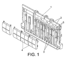
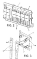
- the general-purpose switch object of this invention is preferably of application for its assembly on the decorative panel of an electrical appliance in which are to be found the switches of an electronic card for activation of the different functions of the appliance, and it fundamentally comprises a one-piece support (1) obtained by means of a single moulding operation in transparent polycarbonate which incorporates some light-transmitting channels (2) of the LED and some pairs, of flexible and parallel securing spring-lugs (3), on each one of which are coupled independent pushbuttons (4).
- Each securing spring-lugs (3) has one or more orifices (5) which, in correspondence with the respective orifices (5) of the other lug constituting the pair, are intended for the insertion of some anchoring elements (6) defined on the rear face of the pushbutton (4), it being foreseen that the pushbutton (4) also has a central appendage (7) on its rear face, which appendage penetrates between the securing spring-lugs (3) that constitute the pair when the pushbutton (4) is pressed, and impinges on the switch of the electronic card activating the corresponding operation, as well as the LED indicating this activation, being made visible through the light-transmitting channels (2).
- the support piece (1) consists of a single piece signifies that the orifices (5) of the securing spring-lugs (3) will always be obtained in the same relative position with respect to the light transmitting channels (2) of the LED, which likewise implies that an equal distance will exist between said transmitting channels (2) and the pushbuttons (4) already mounted on said orifices (5), which will provide a guaranteed assembly when coupling the support (1), with its pushbuttons (4), on the decorative panel.
Landscapes
- Push-Button Switches (AREA)
Applications Claiming Priority (2)
| Application Number | Priority Date | Filing Date | Title |
|---|---|---|---|
| ES200302806U | 2003-12-05 | ||
| ES200302806U ES1056270Y (es) | 2003-12-05 | 2003-12-05 | Conmutador universal. |
Publications (2)
| Publication Number | Publication Date |
|---|---|
| EP1538646A2 true EP1538646A2 (de) | 2005-06-08 |
| EP1538646A3 EP1538646A3 (de) | 2006-05-10 |
Family
ID=31970762
Family Applications (1)
| Application Number | Title | Priority Date | Filing Date |
|---|---|---|---|
| EP04380221A Withdrawn EP1538646A3 (de) | 2003-12-05 | 2004-11-05 | Mehrzweckschalter |
Country Status (2)
| Country | Link |
|---|---|
| EP (1) | EP1538646A3 (de) |
| ES (1) | ES1056270Y (de) |
Cited By (2)
| Publication number | Priority date | Publication date | Assignee | Title |
|---|---|---|---|---|
| DE102006037808A1 (de) * | 2006-08-11 | 2008-02-28 | Siemens Ag | Wippenschaltereinrichtung |
| BE1019778A5 (nl) * | 2011-01-28 | 2012-12-04 | Niko Nv | Bediening. |
Family Cites Families (3)
| Publication number | Priority date | Publication date | Assignee | Title |
|---|---|---|---|---|
| DE8714217U1 (de) * | 1987-10-26 | 1987-12-23 | Preh, Elektrofeinmechanische Werke Jakob Preh Nachf. Gmbh & Co, 8740 Bad Neustadt | Tastenkappe für eine Tastatur |
| US5521342A (en) * | 1994-12-27 | 1996-05-28 | General Motors Corporation | Switch having combined light pipe and printed circuit board |
| DE29715337U1 (de) * | 1997-08-27 | 1997-12-11 | Schwarzbich, Jörg, 33615 Bielefeld | Tasteneinheit |
-
2003
- 2003-12-05 ES ES200302806U patent/ES1056270Y/es not_active Expired - Fee Related
-
2004
- 2004-11-05 EP EP04380221A patent/EP1538646A3/de not_active Withdrawn
Cited By (3)
| Publication number | Priority date | Publication date | Assignee | Title |
|---|---|---|---|---|
| DE102006037808A1 (de) * | 2006-08-11 | 2008-02-28 | Siemens Ag | Wippenschaltereinrichtung |
| DE102006037808B4 (de) * | 2006-08-11 | 2008-05-08 | Siemens Ag | Wippenschaltereinrichtung |
| BE1019778A5 (nl) * | 2011-01-28 | 2012-12-04 | Niko Nv | Bediening. |
Also Published As
| Publication number | Publication date |
|---|---|
| EP1538646A3 (de) | 2006-05-10 |
| ES1056270Y (es) | 2004-06-16 |
| ES1056270U (es) | 2004-03-01 |
Similar Documents
| Publication | Publication Date | Title |
|---|---|---|
| US6388220B1 (en) | Illuminated switching device for stabilized illumination to translucent portion of knob | |
| EP1538646A2 (de) | Mehrzweckschalter | |
| US5087802A (en) | Retaining device for a control button of the piano-key type and device in which same is used | |
| KR20190052976A (ko) | 버스용 콜 부저 스위치 | |
| JPH11154437A (ja) | ステアリングホイール用スイッチ装置 | |
| US6180904B1 (en) | Activation keyboard, particularly for motor-vehicle climate controls | |
| KR950009505Y1 (ko) | 엘리베이터 조작용 버튼 | |
| JPH0236176Y2 (de) | ||
| CN220509894U (zh) | 一种按键开关结构 | |
| CN220491776U (zh) | 一种导光按键 | |
| JPH0518793Y2 (de) | ||
| JPH0735237Y2 (ja) | 押釦スイッチ用防塵カバー | |
| CN223230076U (zh) | 显示模组及清洁设备 | |
| KR100429813B1 (ko) | 전자제품의 조작패널 | |
| KR200255260Y1 (ko) | 광 노브 스위치 조립구조 | |
| GB2278239A (en) | Pushbutton switch assembly | |
| JP3166073B2 (ja) | スイッチ操作パネル | |
| GB2310084A (en) | Electrical switches | |
| KR0136722Y1 (ko) | 모니터의 전원표시렌즈일체형 파워노브장치 | |
| JP2725840B2 (ja) | 自動販売機の押ボタン装置 | |
| JPH021783Y2 (de) | ||
| JPH0414822Y2 (de) | ||
| JPS6214752Y2 (de) | ||
| JPH0338735Y2 (de) | ||
| KR200145516Y1 (ko) | 모니터용 4방향 콘트롤보턴 어셈블리 |
Legal Events
| Date | Code | Title | Description |
|---|---|---|---|
| PUAI | Public reference made under article 153(3) epc to a published international application that has entered the european phase |
Free format text: ORIGINAL CODE: 0009012 |
|
| AK | Designated contracting states |
Kind code of ref document: A2 Designated state(s): AT BE BG CH CY CZ DE DK EE ES FI FR GB GR HU IE IS IT LI LU MC NL PL PT RO SE SI SK TR |
|
| AX | Request for extension of the european patent |
Extension state: AL HR LT LV MK YU |
|
| PUAL | Search report despatched |
Free format text: ORIGINAL CODE: 0009013 |
|
| AK | Designated contracting states |
Kind code of ref document: A3 Designated state(s): AT BE BG CH CY CZ DE DK EE ES FI FR GB GR HU IE IS IT LI LU MC NL PL PT RO SE SI SK TR |
|
| AX | Request for extension of the european patent |
Extension state: AL HR LT LV MK YU |
|
| AKX | Designation fees paid | ||
| REG | Reference to a national code |
Ref country code: DE Ref legal event code: 8566 |
|
| 17P | Request for examination filed |
Effective date: 20070215 |
|
| RBV | Designated contracting states (corrected) |
Designated state(s): AT BE BG CH CY CZ DE DK EE ES FI FR GB GR HU IE IS IT LI LU MC NL PL PT RO SE SI SK TR |
|
| STAA | Information on the status of an ep patent application or granted ep patent |
Free format text: STATUS: THE APPLICATION IS DEEMED TO BE WITHDRAWN |
|
| 18D | Application deemed to be withdrawn |
Effective date: 20090602 |