EP1538579B1 - Méthode et dispositif pour l'économie d'energie dans les détecteurs de mouvement alimentés par batterie - Google Patents
Méthode et dispositif pour l'économie d'energie dans les détecteurs de mouvement alimentés par batterie Download PDFInfo
- Publication number
- EP1538579B1 EP1538579B1 EP04405734A EP04405734A EP1538579B1 EP 1538579 B1 EP1538579 B1 EP 1538579B1 EP 04405734 A EP04405734 A EP 04405734A EP 04405734 A EP04405734 A EP 04405734A EP 1538579 B1 EP1538579 B1 EP 1538579B1
- Authority
- EP
- European Patent Office
- Prior art keywords
- motion detector
- ambient light
- energy
- saving mode
- motion
- Prior art date
- Legal status (The legal status is an assumption and is not a legal conclusion. Google has not performed a legal analysis and makes no representation as to the accuracy of the status listed.)
- Expired - Lifetime
Links
Images
Classifications
-
- G—PHYSICS
- G08—SIGNALLING
- G08B—SIGNALLING OR CALLING SYSTEMS; ORDER TELEGRAPHS; ALARM SYSTEMS
- G08B29/00—Checking or monitoring of signalling or alarm systems; Prevention or correction of operating errors, e.g. preventing unauthorised operation
- G08B29/18—Prevention or correction of operating errors
- G08B29/181—Prevention or correction of operating errors due to failing power supply
-
- G—PHYSICS
- G08—SIGNALLING
- G08B—SIGNALLING OR CALLING SYSTEMS; ORDER TELEGRAPHS; ALARM SYSTEMS
- G08B13/00—Burglar, theft or intruder alarms
- G08B13/18—Actuation by interference with heat, light, or radiation of shorter wavelength; Actuation by intruding sources of heat, light, or radiation of shorter wavelength
- G08B13/189—Actuation by interference with heat, light, or radiation of shorter wavelength; Actuation by intruding sources of heat, light, or radiation of shorter wavelength using passive radiation detection systems
- G08B13/19—Actuation by interference with heat, light, or radiation of shorter wavelength; Actuation by intruding sources of heat, light, or radiation of shorter wavelength using passive radiation detection systems using infrared-radiation detection systems
Definitions
- the invention relates to the field of autonomously operated electrical equipment and installations, and more particularly to battery-operated domestic installation equipment. It is based on a scanning method, a motion detector, a system and an installation according to the preamble of the independent claims.
- Motion detectors are devices that detect people in a defined area or solid angle. They are mainly used in the installation technology. Preferably, they are used to control light sources, fans, heaters or other electrical equipment. If a person moves towards a sensor, then a relay or a semiconductor switch z. B. turned on a lamp. The sensors are based on an infrared detector, which generates a signal according to the radiated temperature of a moving body. Typically, these devices are hard-wired and operated on the low-voltage power supply.
- U.S. Pat. 4 982 176 discloses an outdoor lighting and alarm system with a passive infrared motion detector.
- the system is powered by a battery that is rechargeable via solar cells.
- the battery operation of the lighting or the alarm is activated by an electronic control only if the motion detector has detected a moving object.
- activation of the system during the day with the aid of a daylight detector can be prevented. Measures to reduce the power consumption in the motion detector are not provided.
- EP 1 278 047 A 2 specifies a scanning method for flowmeters in which a sampling rate is reduced as a function of a residual service life of the feed source. As a result, the life of the supply source can be increased at the expense of measuring accuracy.
- JP 102 46 662 A patent abstract discloses an electronic water meter in which a magnetic sensor is present whose sampling rate is adjusted as a function of the sensor signal. To reduce power consumption, the sampling rate is lowered when the sensor signal remains stable or largely unchanged and increases as changes in the sensor signal occur. A reduction in energy consumption as a function of other parameters and in particular a residual life of the supply source is not provided.
- a meter or gas meter is specified, in which the battery state of charge is monitored and the time is determined when the battery should be replaced. Determining the remaining battery capacity or Remaining service life is based inter alia on: a count of the operating days of the battery since its commissioning; a battery self-discharge; a stand-by consumption of the meter; a count of how often certain operating modes of the meter have been performed; a statistical or empirical extrapolation of the putative future energy consumption; and a safety margin to bridge the time between battery alarm and battery replacement. Measures to extend the battery life are not taken.
- the object of the present invention is to provide a method and a device for extending the service life of an autonomous motion detector. This object is achieved by the features of the independent claims.
- the invention consists in a motion sensor, wherein at least one current-consuming component of the motion detector is at least temporarily fed by an autonomous supply source, wherein the motion detector is a measurement signal for detecting the movement or presence of an object and an ambient light signal for detecting ambient light is generated by a photosensitive element, wherein in dependence on the ambient light signal, the motion detector is switched between a mode of operation for detection readiness and a power saving mode for reducing the power consumption of the supply source.
- the method reduces the power consumption of a motion detector with at least partially autonomous power supply without having to restrict the measurement reliability of the motion detector.
- the motion detector or at least one current-consuming component of the motion detector is only woken up and thus the motion detector is put into measurement readiness, if it is clear from the ambient light signal that the result of the movement or presence measurement should actually be used to control the actuator.
- the power consumption of the motion detector can be further reduced.
- the exemplary embodiment according to claim 2a ensures that the power-saving circuit controlled by the ambient light signal is operated in a higher-order manner via the measuring signal detection of the motion detector.
- the motion detector is operated particularly energy-efficient.
- the essential or all power-consuming components are switched off and / or switched to stand-by in energy saving mode.
- the embodiment according to claim 3 has the advantage that the ambient light signal is detected where an actuator is to be controlled in dependence on a person or object detection and a natural or artificial ambient light.
- Claim 4 relates to an embodiment in which the monitoring of the ambient light is controlled by the control unit of the motion detector itself and the monitoring is ensured by the control unit in the energy saving mode.
- the embodiment according to claim 5 has the advantage that, depending on the type of actuator to be controlled, the energy-saving mode can be activated in day mode or in night mode.
- the invention relates to a motion detector comprising measuring means and a control unit for generating and evaluating a measurement signal for detecting the movement or presence of an object and an autonomous supply source for at least temporarily powering at least one current-consuming component of the motion detector, wherein a photosensitive element for generating an ambient light signal in response to an ambient light is present, further wherein the motion detector has a mode of operation for detection readiness and an energy saving mode for reducing the power consumption of the supply source and switching means for automatically switching the motion detector between the operating mode and the energy saving mode depending on a size of the ambient light signal are present.
- the invention also relates to a system comprising a motion detector as described above and an actuator controlled by the motion detector or a device, installation or machine comprising such a motion detector.
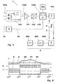
- the detector 1 shows schematically a battery-operated wireless movement or presence detector 1.
- the detector 1 comprises measuring means 100, 101, 102 and a control unit 103 for generating and evaluating a measurement signal 100b, with which the movement or presence 100a of an object can be detected.
- the detector 1 comprises an autonomous supply source 105 for at least temporarily powering at least one power-consuming component 100, 101, 102, 103, 104 of the detector 1.
- the object to be detected may be a person, an animal, a bicycle, a car o act.
- the motion detector 1 is, for example, a passive infrared detector 1 (PIR), but may also be an active infrared detector based on infrared reflection, an active ultrasonic detector based on ultrasonic reflection or Doppler effect, an acoustic sound detector, an active microwave detector or the like.
- PIR passive infrared detector 1
- 100 the widely used passive infrared detector comprising two pyroelectric crystals A, A ', which are opposed to each other Polarity are interconnected.
- a field effect transistor comprising drain D, collector and source S, which is capacitively coupled to ground GND
- the signal amplifier 101 in the A / D converter 102 converted into a digital signal and finally evaluated in the microcontroller 103.
- a separate installation of the detector 1 by the actuator 2 is required.
- the sensor part 1 should be able to be operated with a battery 105 and the switching command from the sensor 1 to the actuator 2 should be transmitted by a wireless connection 3.
- the detector 1 a transmitter 104 and the actuator 2, a receiver 204, which can operate on the basis of radio waves, microwaves, acoustic waves o. ⁇ .
- the actuator 2 comprises its own microcontroller 203 and a switch 200, in particular a relay or a semiconductor switch 200, for controlling a light source, a shutter, a fan, an air conditioning system, a heater or other electrical devices.
- a photosensitive element 5 is present, from which ambient light 5a is detected and a corresponding ambient light signal 5b is forwarded to the motion detector 1 and in particular its microcontroller 103.
- Conventional battery-operated motion detectors 1 then suppress the tripping command to the actuator 2 or the relay 2, without switching to a special power-saving mode.
- the actuation of the actuator 2 is dependent on the motion signal 100b of the motion detector 1 and the ambient light signal 5a of the element 5.
- the ambient light signal 5a is used directly to between the motion detector 1 in response to the ambient light signal 5b a mode of operation 7 for detection readiness and an energy saving mode 8 to reduce the power consumption I of the supply source 105 of the motion detector 1 switch.
- the switching occurs automatically and triggered by the ambient light signal 5b.
- the switching means 103b thus represent a control circuit 103b, which may be arranged inside or outside the control unit 103 and with the aid of which by switching between operating mode 7 and power saving mode 8, the battery life is extended.
- the control circuit switches as a function of the size of the ambient light signal and in no way reduces the measurement reliability of the motion detector 1.
- the control unit 103 comprises the switching means 103b and in particular the microcontroller 103.
- motion sensor 100, data acquisition part or signal processing unit 101, 102, evaluation electronics 103 need only be active for the personal identification and communication part 104 if a predefinable brightness, be it dark or light, is present in the environment. If this is not the case, z. B. the microcontroller 103 are switched to a low-power mode 8 and are awakened only once for the measurement of brightness, for example, once per second. The rest of the electronics 100-104 may remain off during this time.
- the switching means 103b comprise comparator means for comparing the ambient light signal 5b with a predefinable brightness threshold value 60; 61, 62 and computing means for determining the operating mode 7 or energy saving mode 8 in function of the comparison.
- switching means 103b activate the energy saving mode 8 when a light switch 200 is to be controlled by the motion detector 1 and the ambient light signal 5b is above the brightness threshold value 60; 61, 62 or if the motion detector 1 is to control an installation 200 which is to be activated in the case of ambient light 5a, in particular a sun blind or daytime activated or daylight-dependent ventilation, air conditioning or office installation, and the ambient light signal 5b below the brightness threshold value 60; 61, 62 is located.
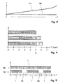
- FIG. 2 shows an exemplary embodiment of a motion detector 1 for activating a light switch 2. Shown is the brightness curve 6 as a function of the time of day t.
- a threshold value 60 in the morning is exceeded, the day energy-saving mode 8 is switched and the motion detector 1 is thus deactivated.
- the evening falls below the brightness threshold 60 is switched to the night operating mode 7 and the motion detector 1 is activated.
- a hysteresis is introduced in such a way that in the morning the threshold value 61, increased by a trigger, and in the evening the threshold value 62, reduced by a trigger, serves as a switching criterion.
- the autonomous power source 105 may be any battery power, including a rechargeable battery or a rechargeable battery.
- the battery 105 may also be arranged outside of the motion detector 1.
- the photosensitive member 5 may be a photocell, a photo-resistor (LDR), phototransistor or the like.
- the photosensitive element 5 is in the range of the motion detector 1 and / or an actuator 2 controlled by the motion detector 1. It may be arranged in particular in the motion detector 1 or optionally in the actuator 2 itself.
- a return communication 4 to the detector 1 may also be present.
- the return communication 4 is used to tell from the actuator 2 to the detector 1, how good the transmission connection works and to regulate the transmission power to an optimum level if necessary and in particular to lower.
- the invention also relates to a motion detection system comprising a motion detector 1 as described above and an actuator 2 controlled by the motion detector 1, as well as a device, an installation or a machine comprising such a motion detector 1.
- the invention relates to a scanning method for a motion detector 1, wherein at least one power-consuming component 100, 101, 102, 103, 104 of the motion detector 1 is at least temporarily fed by an autonomous power source 105, wherein the motion detector 1, a measurement signal 100b for detection the motion or presence 100a of an object and of a photosensitive element 5, an ambient light signal 5b for detecting ambient light 5a is generated, further depending on the ambient light signal 5b, the motion detector 1 between a mode of operation 7 for DetektionsrMft and a power saving mode 8 for reducing the power consumption of the I Power source 105 is switched.
- a mode of operation 7 for DetektionsrMft for Detektions
- the motion detector can be put into operating mode 7 or energy-saving mode 8 independently of the measuring signal 100b.
- the energy-saving mode can be activated by default.
- the ambient light 5a is measured in the region of the motion detector 1 and / or an actuator 2 controlled by the motion detector 1; this may be daylight 5a and / or artificial light 5a.
- a measurement of the ambient light 5a is initiated by a control unit 103 of the motion detector 1 and the resulting ambient light signal 5b is initiated with a brightness threshold value 60; 61, 62, which in particular is hysteresis-type and activated as a function of the comparison of the operating mode 7 or the energy-saving mode 8.
- the control unit 103 is switched to standby insofar that it is activated automatically and only as necessary for the repeated measurement of the ambient light 5a.
- the microcontroller 103 runs a clock, for example, the microcontroller 103 wakes every 1 s or 10 s and initiates measurement.
- the control unit 103 thus runs only in a minimal configuration which serves for periodic or repeated monitoring of the environment for brightness 5a and for occasional waking up of the entire motion detector 1.
- a light switch 200 is controlled by the motion detector 1 and activated on the basis of the comparison of the energy-saving mode 8 when the brightness threshold value 60; 61, 62 is exceeded by the ambient light 5a.
- the comparison is thus carried out so that the motion detector 1 is largely inactive in daylight and in the dark in detection readiness.
- the movement detector 1 can control an installation 200 to be activated in the case of ambient light 5a, in particular a sun-blind 200 or day-activated ventilation, air-conditioning or office installation, and be activated on the basis of the comparison of the energy-saving mode 8 if the brightness threshold value 60; 61, 62 is fallen below by ambient light 5a.
- a sampling rate f 1 , f 2 , f 3 can be reduced with a decreasing residual life of the supply source 105 (FIGS. 3, 4).
- a sampling rate f, 13 can be left unchanged and intermittent sampling gaps 14 can be permitted (FIG. 5).
- Fig. 3 shows the power consumption I of a data acquisition system 101-103 or microcontroller 103 as a function of the sampling rate or clock frequency f.
- the total power consumption I, 11 is composed of a base load 10 and a dependent of the sampling frequency f part.
- the base load 10 is composed of the power consumption of the microcontroller 103 in the sleep mode, the consumption of the amplifier 101 and the sensor 100 (if they can not be turned off) as well as leakage currents of other components.
- the frequency-dependent part increases substantially proportionally and at high frequencies f disproportionately to the frequency f.
- the power consumption I of a data acquisition system 101-103 e.g. of an analog-to-digital converter 102, are approximately halved when the sampling rate f is reduced by a factor of two.
- the relevant sampling rates f of the infrared motion detector 1 for the evaluation and detection of a person are in a frequency range between about 0.1 Hz and 10 Hz.
- Fig. 5 shows an alternative or supplementary scanning method in which a burst mode scan is performed.
- a signal is detected by equidistant or at least continuous scans 12.
- sampling may also be performed in a burst mode 13 by allowing sense or sampling gaps 14.
- the sampling rate f remains unchanged, but is temporarily suspended or interrupted.
- the burst mode 13 can basically be operated independently of a remaining service life of the battery 105.
- the power consumption I can be reduced the more, the longer the coverage gaps 14 are selected in burst mode 13.
- the penalty is that the traceability of the motion signal 100b becomes worse and, in essence, the response time is increased until movement 100a can be detected.
- a good compromise is when a dead-time 14 or sleep-mode 14 wake-time ratio is chosen so that people can not pass unguarded or unnoticed an area to be controlled.
- a dead time 14 or detection gap 14 of 100 ms to a few 100 ms is generally tolerable.
- the burst mode 13 can always allow for longer sampling intervals 14 with increasing battery life, so that the battery life remains intermittently available with ever lower availability for long periods of time.
- the scanning methods according to FIGS. 4 and 5 are freely combinable with the method according to the invention and in particular with each other. Overall, a minimum sampling rate over a minimum period should be ensured in any case for detecting moving persons, cyclists, cars o. ⁇ .
- the reduction of the sampling frequency f 1 , f 2 , f 3 and the admission of sampling gaps 14 will also be determined depending on a spatial area to be monitored, a field of view and in dependence of several motion detectors 1.
Landscapes
- Physics & Mathematics (AREA)
- General Physics & Mathematics (AREA)
- Engineering & Computer Science (AREA)
- Computer Security & Cryptography (AREA)
- Photometry And Measurement Of Optical Pulse Characteristics (AREA)
- Geophysics And Detection Of Objects (AREA)
- Length Measuring Devices By Optical Means (AREA)
- Measurement Of Optical Distance (AREA)
- Charge And Discharge Circuits For Batteries Or The Like (AREA)
Claims (13)
- Procédé de balayage pour un détecteur de mouvement (1), dans lequel au moins un composant consommateur de courant (100, 101, 102, 103, 104) du détecteur de mouvement (1) est alimenté au moins temporairement par une source d'alimentation autonome (105), dans lequel le détecteur de mouvement (1) émet un signal de mesure (100b) pour détecter le mouvement ou la présence (100a) d'un objet et un élément photosensible (5) émettant un signal d'ambiance (5b) pour la détection de la lumière ambiante (5a), et dans lequel, en fonction du signal d'ambiance (5b), le détecteur de mouvement (1) commute entre un mode de service (7) où il est prêt pour la détection et un mode d'économie d'énergie (8) pour la réduction de la consommation électrique (I) de la source d'alimentation (105),
caractérisé en ce qu'en vue de réduire la consommation électrique (I) de la source d'alimentation (105) dans le mode de service,a) un taux de balayage (f1, f2, f3) est réduit lorsque la durée de vie résiduelle de la source d'alimentation (105) diminue, et/oub) un taux de balayage (f, 13) reste inchangé et des intervalles sans balayage (14) intermittents sont autorisés. - Procédé de balayage selon la revendication 1, caractérisé en ce quea) le détecteur de mouvement (1) est commuté dans le mode de service (7) ou le mode d'économie d'énergie (8) indépendamment du signal de mesure (100b) et/oub) le mode d'économie d'énergie est activé par défaut et/ouc) dans le mode d'économie d'énergie (8), l'un au moins des composants consommateurs de courant (100, 101, 102, 103, 104) au nombre d'un au moins du détecteur de mouvement (1), et en particulier chacun des composants consommateurs de courant (100, 101, 102, 103, 104), est arrêté ou mis en veille.
- Procédé de balayage selon l'une quelconque des revendications précédentes,
caractérisé en ce quea) la lumière ambiante (5a) est mesurée au niveau du détecteur de mouvement (1) et/ou d'un élément d'actionnement (2) contrôlé par le détecteur de mouvement (1) et/oub) la lumière ambiante (5a) est la lumière du jour et/ou une lumière artificielle. - Procédé de balayage selon l'une quelconque des revendications précédentes,
caractérisé en ce quea) une unité de contrôle (103) du détecteur de mouvement (1) déclenche de manière répétitive une mesure de la lumière ambiante (5a) et compare le signal d'ambiance (5b) en résultant à un seuil de luminosité (60 ; 61, 62), qui est notamment affecté d'une hystérésis,b) en fonction de la comparaison, le mode de service (7) ou le mode d'économie d'énergie (8) est activé etc) dans le mode d'économie d'énergie (8), l'unité de contrôle (103) est mise en veille de façon à pouvoir s'activer automatiquement et seulement dans la mesure nécessaire à la mesure répétitive de la lumière ambiante(5a). - Procédé de balayage selon la revendication 4, caractérisé en ce quea) le détecteur de mouvement (1) contrôle un interrupteur d'éclairage (200) et le mode d'économie d'énergie (8) est activé sur la base de la comparaison lorsque la lumière ambiante (5a) dépasse le seuil de luminosité (60 ; 61, 62), oub) le détecteur de mouvement (1) contrôle une installation (200) devant être activée en présence de lumière ambiante (5a), en particulier un store pare-soleil (200) ou une ventilation, un climatiseur ou une installation de bureau pouvant être activés dans la journée, et le mode d'économie d'énergie (8) est activé sur la base de la comparaison lorsque la lumière ambiante (5a) passe en dessous du seuil de luminosité (60 ; 61, 62).
- Détecteur de mouvement (1) comprenant des moyens de mesure (100, 101, 102) et une unité de contrôle (103) pour produire et interpréter un signal de mesure (100b) en vue de la détection du mouvement ou de la présence (100a) d'un objet ainsi qu'une source d'alimentation autonome (105) pour l'alimentation au moins temporaire d'au moins une composant consommateur de courant (100, 101, 102, 103, 104) du détecteur de mouvement (1), dans lequel est prévu en outre un élément photosensible (5) destiné à produire un signal d'ambiance (5a) en fonction d'une lumière ambiante (5a), et dans lequela) le détecteur de mouvement (1) comprend un mode de service (7) dans lequel il est préparé pour la détection et un mode d'économie d'énergie (8) pour réduire la consommation électrique (I) de la source d'alimentation (105) etb) il est prévu des moyens de commutation (103b) pour la commutation automatique du détecteur de mouvement (1) entre le mode de service (7) et le mode d'économie d'énergie (8) en fonction d'une grandeur du signal d'ambiance (5b),
caractérisé en ce qu'en vue de réduire la consommation électrique (I) de la source d'alimentation (105) en mode de service,c) un taux de balayage (f1, f2, f3) est réduit lorsque la durée de vie résiduelle de la source d'alimentation (105) diminue, et/oud) un taux de balayage (f, 13) reste inchangé et des intervalles sans balayage (14) intermittents sont autorisés. - Détecteur de mouvement (1) selon la revendication 6, caractérisé en ce quea) dans le mode d'économie d'énergie (8), chaque moyen de mesure (100, 101, 102) est arrêté ou mis en veille et l'unité de contrôle (103) est mise en veille de façon à pouvoir s'activer automatiquement et seulement dans la mesure nécessaire à la mesure répétitive de la lumière ambiante(5a), et/oub) l'unité de contrôle (103) contient les moyens de commutation (103b) et est en particulier un microcontrôleur (103).
- Détecteur de mouvement (1) selon l'une quelconque des revendications 6 à 7,
caractérisé en ce quea) les moyens de commutation (103b) comprennent des moyens comparateurs pour comparer le signal d'ambiance (5b) à un seuil de luminosité (60; 61, 62) pouvant être prédéterminé, etb) les moyens de commutation (103b) comprennent des moyens de calcul pour déterminer le mode de service (7) ou le mode d'économie d'énergie (8) en fonction de la comparaison. - Détecteur de mouvement (1) selon la revendication 8, caractérisé en ce que les moyens de commutation (103b) activent le mode d'économie d'énergie (8) sia) le détecteur de mouvement (1) doit contrôler un interrupteur d'éclairage (200) et le signal d'ambiance (5b) dépasse le seuil de luminosité (60 ; 61, 62) oub) le détecteur de mouvement (1) doit contrôler une installation (200) qui doit être activée en présence de lumière ambiante (5a), en particulier un store pare-soleil (200) ou une ventilation, un climatiseur ou une installation de bureau pouvant être activés dans la journée, et si le signal d'ambiance (5b) est inférieur au seuil de luminosité (60 ; 61, 62).
- Détecteur de mouvement (1) selon l'une quelconque des revendications 6 à 9,
caractérisé en ce quea) les moyens de mesure (100, 101, 102) comprennent un capteur de mouvement (100), une unité de traitement des signaux (101, 102), en particulier un amplificateur de signaux (101), et un convertisseur analogique-numérique (102), et des moyens de communication (104) pour la commande d'un organe d'actionnement (2) etb) en particulier en ce que le capteur de mouvement (100) est conçu en vue de la détection de personnes, d'animaux et/ou de véhicules et est de préférence un détecteur à infrarouges passif (1). - Détecteur de mouvement (1) selon l'une quelconque des revendications 6 à 10,
caractérisé en ce quea) la source d'alimentation (105) est une alimentation sur batterie (105) du détecteur de mouvement (1), en particulier une batterie rechargeable, et/oub) l'élément photosensible (5) est disposé au niveau du détecteur de mouvement (1) et/ou d'un organe d'actionnement (2) commandé par le détecteur de mouvement (1), et/ouc) il est prévu des moyens de communication en retour sans fil (4) entre l'organe d'actionnement (2) et le détecteur de mouvement (1) et d'adaptation d'une puissance d'émetteur du détecteur de mouvement (1) à un niveau nécessaire. - Système de détection de mouvement comprenant un détecteur de mouvement (1) selon l'une quelconque des revendications 6 à 11 et un organe d'actionnement (2) contrôlé par le détecteur de mouvement (1).
- Appareil, installation ou machine comprenant un détecteur de mouvement (1) selon l'une quelconque des revendications 6 à 11.
Applications Claiming Priority (2)
| Application Number | Priority Date | Filing Date | Title |
|---|---|---|---|
| DE10356071A DE10356071A1 (de) | 2003-12-01 | 2003-12-01 | Verfahren und Vorrichtung zur Reduktion des Stromverbrauchs in batteriebetriebenen Bewegungsmeldern |
| DE10356071 | 2003-12-01 |
Publications (2)
| Publication Number | Publication Date |
|---|---|
| EP1538579A1 EP1538579A1 (fr) | 2005-06-08 |
| EP1538579B1 true EP1538579B1 (fr) | 2006-09-27 |
Family
ID=34442381
Family Applications (1)
| Application Number | Title | Priority Date | Filing Date |
|---|---|---|---|
| EP04405734A Expired - Lifetime EP1538579B1 (fr) | 2003-12-01 | 2004-11-25 | Méthode et dispositif pour l'économie d'energie dans les détecteurs de mouvement alimentés par batterie |
Country Status (3)
| Country | Link |
|---|---|
| EP (1) | EP1538579B1 (fr) |
| AT (1) | ATE341058T1 (fr) |
| DE (2) | DE10356071A1 (fr) |
Families Citing this family (10)
| Publication number | Priority date | Publication date | Assignee | Title |
|---|---|---|---|---|
| DE102005042568B3 (de) * | 2005-09-08 | 2007-01-04 | Abb Research Ltd. | Funk-Bewegungsmelder |
| GB0616282D0 (en) * | 2006-08-16 | 2006-09-27 | Circuitree Ltd | Context Monitoring For Remote Sensor Platform |
| DE102008004420A1 (de) * | 2008-01-14 | 2009-07-16 | Elmos Semiconductor Ag | Beleuchtungssystem für Innenräume sowie Verfahren zu dessen Steuerung |
| DE102008004419A1 (de) * | 2008-01-14 | 2009-07-16 | Elmos Semiconductor Ag | Beleuchtungsvorrichtung als Außenbeleuchtung und Verfahren zu deren Steuerung |
| DE102008057042B4 (de) * | 2008-11-12 | 2013-03-28 | Waldemar Stach | Stromsparende Sensorschaltung |
| US8665090B2 (en) | 2009-01-26 | 2014-03-04 | Lutron Electronics Co., Inc. | Multi-modal load control system having occupancy sensing |
| EP2438798B1 (fr) * | 2009-06-04 | 2018-09-26 | Philips Lighting Holding B.V. | Réactivation d'un capteur de lumière dans un système d'éclairage |
| US11525735B2 (en) | 2016-01-11 | 2022-12-13 | Carrier Corporation | Infrared presence detector system |
| DE102016124796A1 (de) * | 2016-12-19 | 2018-06-21 | Endress+Hauser Conducta Gmbh+Co. Kg | Sensorkopfmodul zur kontinuierlichen automatisierten Datenerfassung |
| CN114166356B (zh) * | 2021-12-06 | 2024-02-13 | 普联技术有限公司 | Pir阈值调整方法、pir阈值调整系统以及监测装置 |
Family Cites Families (6)
| Publication number | Priority date | Publication date | Assignee | Title |
|---|---|---|---|---|
| US4890093A (en) * | 1988-10-27 | 1989-12-26 | Schlage Lock Company | Solar powered proximity triggered light |
| US5128654A (en) * | 1990-02-23 | 1992-07-07 | Lightolier Incorporated | Preset light controller including infrared sensor operable in multiple modes |
| US5973594A (en) * | 1995-03-29 | 1999-10-26 | Hubbell Incorporated | Multiple optical designs for a multifunction sensor |
| US5892446A (en) * | 1997-03-10 | 1999-04-06 | Reich; Lee A. | Wild animal deterrent device |
| DE19814591A1 (de) * | 1998-04-01 | 1999-10-07 | Merten Gmbh & Co Kg Geb | Verfahren und Präsenzmelder zum Steuern einer Beleuchtungseinrichtung |
| DE19913841A1 (de) * | 1999-03-27 | 2000-09-28 | Hansjoerg Klein | System zur Überwachung von schützenswerten Objekten in Räumen von Immobilien oder von mobilem Eigentum |
-
2003
- 2003-12-01 DE DE10356071A patent/DE10356071A1/de not_active Withdrawn
-
2004
- 2004-11-25 DE DE502004001582T patent/DE502004001582D1/de not_active Expired - Lifetime
- 2004-11-25 AT AT04405734T patent/ATE341058T1/de not_active IP Right Cessation
- 2004-11-25 EP EP04405734A patent/EP1538579B1/fr not_active Expired - Lifetime
Also Published As
| Publication number | Publication date |
|---|---|
| DE502004001582D1 (de) | 2006-11-09 |
| EP1538579A1 (fr) | 2005-06-08 |
| DE10356071A1 (de) | 2005-06-23 |
| ATE341058T1 (de) | 2006-10-15 |
Similar Documents
| Publication | Publication Date | Title |
|---|---|---|
| WO2005055017A2 (fr) | Procede et dispositif de reduction du consommateur de courant dans des appareils a accumulateurs | |
| EP1538579B1 (fr) | Méthode et dispositif pour l'économie d'energie dans les détecteurs de mouvement alimentés par batterie | |
| DE60128684T2 (de) | Prozessorgest tzter drahtloser detektor | |
| CN107113479B (zh) | 传感器节点和传感器节点的控制方法 | |
| EP1435079A1 (fr) | Systeme de detection sans fil | |
| DE212014000144U1 (de) | Gefahrenmeldeanlagen mit gegabelten Prozessoren | |
| DE212014000109U1 (de) | Kontextadaptive Kühlung-Durch-Trocknung-Funktion für HLK-Steuerung | |
| CN107631802B (zh) | 被动式红外探测器的控制方法和装置 | |
| EP0724044A1 (fr) | Dispositif de commande d'une armature sanitaire | |
| EP2954647B1 (fr) | Procédé et dispositif de commande pour mettre en marche et arrêter un mode de fonctionnement nocturne d'une installation de chauffage et/ou de climatisation | |
| EP0900417A1 (fr) | Systeme d'automatisation domestique ou d'immeuble | |
| DE10393173T5 (de) | Bestätigungseinheit für bewegbare Barrieren mit Energiemanagementsteuerung und entsprechendem Verfahren | |
| CN108077105B (zh) | 一种宠物窝环境控制方法及其装置、宠物窝 | |
| US20220163938A1 (en) | Control method, motorised drive device, home automation installation comprising such a motorised drive device | |
| JP2003339301A (ja) | 鳥獣害防止装置 | |
| CN106440213A (zh) | 空调及其控制方法和控制系统 | |
| EP2674014B1 (fr) | Capteur d'occupation | |
| CN106658893A (zh) | 一种照明控制方法、装置以及探测设备、照明系统 | |
| KR20220135943A (ko) | 대상 영역의 재실을 감지하여 대상 영역의 환경을 제어하는 방법 | |
| EP2453426B1 (fr) | Capteur de surveillance doté d'un autotest | |
| Adelakun et al. | Automatic control and monitoring of electrical energy consumption using PIR sensor module | |
| DE102015205936B4 (de) | Selbstregulierende Vorrichtung zur Energieeinsparung für Fensterrahmen | |
| DE102021107400A1 (de) | Verfahren zum Betrieb eines ToF-Sensorelements, Verwendung eines ToF-Sensorelements, Sanitären Einrichtung und Computerprogramm | |
| FI131591B1 (en) | Control system and method for controlling indoor environmental conditions | |
| DE102012100080A1 (de) | Verfahren zur Bewegungserfassung und Bewegungserfassungssystem |
Legal Events
| Date | Code | Title | Description |
|---|---|---|---|
| PUAI | Public reference made under article 153(3) epc to a published international application that has entered the european phase |
Free format text: ORIGINAL CODE: 0009012 |
|
| AK | Designated contracting states |
Kind code of ref document: A1 Designated state(s): AT BE BG CH CY CZ DE DK EE ES FI FR GB GR HU IE IS IT LI LU MC NL PL PT RO SE SI SK TR |
|
| AX | Request for extension of the european patent |
Extension state: AL HR LT LV MK YU |
|
| 17P | Request for examination filed |
Effective date: 20051010 |
|
| AKX | Designation fees paid |
Designated state(s): AT BE BG CH CY CZ DE DK EE ES FI FR GB GR HU IE IS IT LI LU MC NL PL PT RO SE SI SK TR |
|
| GRAP | Despatch of communication of intention to grant a patent |
Free format text: ORIGINAL CODE: EPIDOSNIGR1 |
|
| GRAS | Grant fee paid |
Free format text: ORIGINAL CODE: EPIDOSNIGR3 |
|
| GRAA | (expected) grant |
Free format text: ORIGINAL CODE: 0009210 |
|
| AK | Designated contracting states |
Kind code of ref document: B1 Designated state(s): AT BE BG CH CY CZ DE DK EE ES FI FR GB GR HU IE IS IT LI LU MC NL PL PT RO SE SI SK TR |
|
| PG25 | Lapsed in a contracting state [announced via postgrant information from national office to epo] |
Ref country code: IT Free format text: LAPSE BECAUSE OF FAILURE TO SUBMIT A TRANSLATION OF THE DESCRIPTION OR TO PAY THE FEE WITHIN THE PRESCRIBED TIME-LIMIT;WARNING: LAPSES OF ITALIAN PATENTS WITH EFFECTIVE DATE BEFORE 2007 MAY HAVE OCCURRED AT ANY TIME BEFORE 2007. THE CORRECT EFFECTIVE DATE MAY BE DIFFERENT FROM THE ONE RECORDED. Effective date: 20060927 Ref country code: SK Free format text: LAPSE BECAUSE OF FAILURE TO SUBMIT A TRANSLATION OF THE DESCRIPTION OR TO PAY THE FEE WITHIN THE PRESCRIBED TIME-LIMIT Effective date: 20060927 Ref country code: SI Free format text: LAPSE BECAUSE OF FAILURE TO SUBMIT A TRANSLATION OF THE DESCRIPTION OR TO PAY THE FEE WITHIN THE PRESCRIBED TIME-LIMIT Effective date: 20060927 Ref country code: PL Free format text: LAPSE BECAUSE OF FAILURE TO SUBMIT A TRANSLATION OF THE DESCRIPTION OR TO PAY THE FEE WITHIN THE PRESCRIBED TIME-LIMIT Effective date: 20060927 Ref country code: RO Free format text: LAPSE BECAUSE OF FAILURE TO SUBMIT A TRANSLATION OF THE DESCRIPTION OR TO PAY THE FEE WITHIN THE PRESCRIBED TIME-LIMIT Effective date: 20060927 Ref country code: NL Free format text: LAPSE BECAUSE OF FAILURE TO SUBMIT A TRANSLATION OF THE DESCRIPTION OR TO PAY THE FEE WITHIN THE PRESCRIBED TIME-LIMIT Effective date: 20060927 Ref country code: FI Free format text: LAPSE BECAUSE OF FAILURE TO SUBMIT A TRANSLATION OF THE DESCRIPTION OR TO PAY THE FEE WITHIN THE PRESCRIBED TIME-LIMIT Effective date: 20060927 Ref country code: IE Free format text: LAPSE BECAUSE OF FAILURE TO SUBMIT A TRANSLATION OF THE DESCRIPTION OR TO PAY THE FEE WITHIN THE PRESCRIBED TIME-LIMIT Effective date: 20060927 Ref country code: CZ Free format text: LAPSE BECAUSE OF FAILURE TO SUBMIT A TRANSLATION OF THE DESCRIPTION OR TO PAY THE FEE WITHIN THE PRESCRIBED TIME-LIMIT Effective date: 20060927 |
|
| REG | Reference to a national code |
Ref country code: GB Ref legal event code: FG4D Free format text: NOT ENGLISH |
|
| REG | Reference to a national code |
Ref country code: CH Ref legal event code: EP |
|
| REG | Reference to a national code |
Ref country code: IE Ref legal event code: FG4D Free format text: LANGUAGE OF EP DOCUMENT: GERMAN |
|
| REF | Corresponds to: |
Ref document number: 502004001582 Country of ref document: DE Date of ref document: 20061109 Kind code of ref document: P |
|
| PG25 | Lapsed in a contracting state [announced via postgrant information from national office to epo] |
Ref country code: MC Free format text: LAPSE BECAUSE OF NON-PAYMENT OF DUE FEES Effective date: 20061130 Ref country code: BE Free format text: LAPSE BECAUSE OF NON-PAYMENT OF DUE FEES Effective date: 20061130 |
|
| PG25 | Lapsed in a contracting state [announced via postgrant information from national office to epo] |
Ref country code: SE Free format text: LAPSE BECAUSE OF FAILURE TO SUBMIT A TRANSLATION OF THE DESCRIPTION OR TO PAY THE FEE WITHIN THE PRESCRIBED TIME-LIMIT Effective date: 20061227 Ref country code: BG Free format text: LAPSE BECAUSE OF FAILURE TO SUBMIT A TRANSLATION OF THE DESCRIPTION OR TO PAY THE FEE WITHIN THE PRESCRIBED TIME-LIMIT Effective date: 20061227 Ref country code: DK Free format text: LAPSE BECAUSE OF FAILURE TO SUBMIT A TRANSLATION OF THE DESCRIPTION OR TO PAY THE FEE WITHIN THE PRESCRIBED TIME-LIMIT Effective date: 20061227 |
|
| PG25 | Lapsed in a contracting state [announced via postgrant information from national office to epo] |
Ref country code: ES Free format text: LAPSE BECAUSE OF FAILURE TO SUBMIT A TRANSLATION OF THE DESCRIPTION OR TO PAY THE FEE WITHIN THE PRESCRIBED TIME-LIMIT Effective date: 20070107 |
|
| PG25 | Lapsed in a contracting state [announced via postgrant information from national office to epo] |
Ref country code: IS Free format text: LAPSE BECAUSE OF FAILURE TO SUBMIT A TRANSLATION OF THE DESCRIPTION OR TO PAY THE FEE WITHIN THE PRESCRIBED TIME-LIMIT Effective date: 20070127 |
|
| NLV1 | Nl: lapsed or annulled due to failure to fulfill the requirements of art. 29p and 29m of the patents act | ||
| PG25 | Lapsed in a contracting state [announced via postgrant information from national office to epo] |
Ref country code: PT Free format text: LAPSE BECAUSE OF FAILURE TO SUBMIT A TRANSLATION OF THE DESCRIPTION OR TO PAY THE FEE WITHIN THE PRESCRIBED TIME-LIMIT Effective date: 20070313 |
|
| REG | Reference to a national code |
Ref country code: IE Ref legal event code: FD4D |
|
| GBV | Gb: ep patent (uk) treated as always having been void in accordance with gb section 77(7)/1977 [no translation filed] |
Effective date: 20060927 |
|
| EN | Fr: translation not filed | ||
| PLBE | No opposition filed within time limit |
Free format text: ORIGINAL CODE: 0009261 |
|
| STAA | Information on the status of an ep patent application or granted ep patent |
Free format text: STATUS: NO OPPOSITION FILED WITHIN TIME LIMIT |
|
| 26N | No opposition filed |
Effective date: 20070628 |
|
| PG25 | Lapsed in a contracting state [announced via postgrant information from national office to epo] |
Ref country code: GB Free format text: LAPSE BECAUSE OF FAILURE TO SUBMIT A TRANSLATION OF THE DESCRIPTION OR TO PAY THE FEE WITHIN THE PRESCRIBED TIME-LIMIT Effective date: 20060927 |
|
| BERE | Be: lapsed |
Owner name: ABB RESEARCH LTD. Effective date: 20061130 |
|
| PG25 | Lapsed in a contracting state [announced via postgrant information from national office to epo] |
Ref country code: AT Free format text: LAPSE BECAUSE OF NON-PAYMENT OF DUE FEES Effective date: 20061125 |
|
| PG25 | Lapsed in a contracting state [announced via postgrant information from national office to epo] |
Ref country code: GR Free format text: LAPSE BECAUSE OF FAILURE TO SUBMIT A TRANSLATION OF THE DESCRIPTION OR TO PAY THE FEE WITHIN THE PRESCRIBED TIME-LIMIT Effective date: 20061228 Ref country code: FR Free format text: LAPSE BECAUSE OF FAILURE TO SUBMIT A TRANSLATION OF THE DESCRIPTION OR TO PAY THE FEE WITHIN THE PRESCRIBED TIME-LIMIT Effective date: 20070525 |
|
| PG25 | Lapsed in a contracting state [announced via postgrant information from national office to epo] |
Ref country code: EE Free format text: LAPSE BECAUSE OF FAILURE TO SUBMIT A TRANSLATION OF THE DESCRIPTION OR TO PAY THE FEE WITHIN THE PRESCRIBED TIME-LIMIT Effective date: 20060927 |
|
| PG25 | Lapsed in a contracting state [announced via postgrant information from national office to epo] |
Ref country code: HU Free format text: LAPSE BECAUSE OF FAILURE TO SUBMIT A TRANSLATION OF THE DESCRIPTION OR TO PAY THE FEE WITHIN THE PRESCRIBED TIME-LIMIT Effective date: 20070328 Ref country code: LU Free format text: LAPSE BECAUSE OF NON-PAYMENT OF DUE FEES Effective date: 20061125 Ref country code: TR Free format text: LAPSE BECAUSE OF FAILURE TO SUBMIT A TRANSLATION OF THE DESCRIPTION OR TO PAY THE FEE WITHIN THE PRESCRIBED TIME-LIMIT Effective date: 20060927 |
|
| PG25 | Lapsed in a contracting state [announced via postgrant information from national office to epo] |
Ref country code: CY Free format text: LAPSE BECAUSE OF FAILURE TO SUBMIT A TRANSLATION OF THE DESCRIPTION OR TO PAY THE FEE WITHIN THE PRESCRIBED TIME-LIMIT Effective date: 20060927 Ref country code: FR Free format text: LAPSE BECAUSE OF FAILURE TO SUBMIT A TRANSLATION OF THE DESCRIPTION OR TO PAY THE FEE WITHIN THE PRESCRIBED TIME-LIMIT Effective date: 20060927 |
|
| REG | Reference to a national code |
Ref country code: CH Ref legal event code: PL |
|
| PG25 | Lapsed in a contracting state [announced via postgrant information from national office to epo] |
Ref country code: CH Free format text: LAPSE BECAUSE OF NON-PAYMENT OF DUE FEES Effective date: 20081130 Ref country code: LI Free format text: LAPSE BECAUSE OF NON-PAYMENT OF DUE FEES Effective date: 20081130 |
|
| PGFP | Annual fee paid to national office [announced via postgrant information from national office to epo] |
Ref country code: DE Payment date: 20091120 Year of fee payment: 6 |
|
| REG | Reference to a national code |
Ref country code: DE Ref legal event code: R119 Ref document number: 502004001582 Country of ref document: DE Effective date: 20110601 Ref country code: DE Ref legal event code: R119 Ref document number: 502004001582 Country of ref document: DE Effective date: 20110531 |
|
| PG25 | Lapsed in a contracting state [announced via postgrant information from national office to epo] |
Ref country code: DE Free format text: LAPSE BECAUSE OF NON-PAYMENT OF DUE FEES Effective date: 20110531 |