EP1538579B1 - Method and device for power saving in battery driven movement detectors. - Google Patents
Method and device for power saving in battery driven movement detectors. Download PDFInfo
- Publication number
- EP1538579B1 EP1538579B1 EP04405734A EP04405734A EP1538579B1 EP 1538579 B1 EP1538579 B1 EP 1538579B1 EP 04405734 A EP04405734 A EP 04405734A EP 04405734 A EP04405734 A EP 04405734A EP 1538579 B1 EP1538579 B1 EP 1538579B1
- Authority
- EP
- European Patent Office
- Prior art keywords
- motion detector
- ambient light
- energy
- saving mode
- motion
- Prior art date
- Legal status (The legal status is an assumption and is not a legal conclusion. Google has not performed a legal analysis and makes no representation as to the accuracy of the status listed.)
- Active
Links
- 230000033001 locomotion Effects 0.000 title claims abstract description 131
- 238000000034 method Methods 0.000 title claims abstract description 17
- 238000001514 detection method Methods 0.000 claims abstract description 20
- 238000005259 measurement Methods 0.000 claims abstract description 19
- 238000009434 installation Methods 0.000 claims abstract description 18
- 230000009467 reduction Effects 0.000 claims abstract description 7
- 238000004891 communication Methods 0.000 claims description 10
- 238000004378 air conditioning Methods 0.000 claims description 5
- 238000009423 ventilation Methods 0.000 claims description 4
- 230000003247 decreasing effect Effects 0.000 claims description 3
- 241001465754 Metazoa Species 0.000 claims description 2
- 238000012545 processing Methods 0.000 claims description 2
- 238000005070 sampling Methods 0.000 description 26
- 230000001419 dependent effect Effects 0.000 description 5
- 230000008901 benefit Effects 0.000 description 3
- 230000005540 biological transmission Effects 0.000 description 3
- 239000013078 crystal Substances 0.000 description 3
- 238000005265 energy consumption Methods 0.000 description 3
- 238000011156 evaluation Methods 0.000 description 3
- 238000012544 monitoring process Methods 0.000 description 3
- 230000004044 response Effects 0.000 description 3
- 230000005855 radiation Effects 0.000 description 2
- 239000004065 semiconductor Substances 0.000 description 2
- 230000003213 activating effect Effects 0.000 description 1
- 230000004913 activation Effects 0.000 description 1
- 230000032683 aging Effects 0.000 description 1
- 238000010586 diagram Methods 0.000 description 1
- 230000000694 effects Effects 0.000 description 1
- 238000005516 engineering process Methods 0.000 description 1
- 238000013213 extrapolation Methods 0.000 description 1
- 230000005669 field effect Effects 0.000 description 1
- 230000000737 periodic effect Effects 0.000 description 1
- 230000002035 prolonged effect Effects 0.000 description 1
- 239000007787 solid Substances 0.000 description 1
- 230000007704 transition Effects 0.000 description 1
- 230000001960 triggered effect Effects 0.000 description 1
- 230000002618 waking effect Effects 0.000 description 1
- XLYOFNOQVPJJNP-UHFFFAOYSA-N water Substances O XLYOFNOQVPJJNP-UHFFFAOYSA-N 0.000 description 1
Images
Classifications
-
- G—PHYSICS
- G08—SIGNALLING
- G08B—SIGNALLING OR CALLING SYSTEMS; ORDER TELEGRAPHS; ALARM SYSTEMS
- G08B29/00—Checking or monitoring of signalling or alarm systems; Prevention or correction of operating errors, e.g. preventing unauthorised operation
- G08B29/18—Prevention or correction of operating errors
- G08B29/181—Prevention or correction of operating errors due to failing power supply
-
- G—PHYSICS
- G08—SIGNALLING
- G08B—SIGNALLING OR CALLING SYSTEMS; ORDER TELEGRAPHS; ALARM SYSTEMS
- G08B13/00—Burglar, theft or intruder alarms
- G08B13/18—Actuation by interference with heat, light, or radiation of shorter wavelength; Actuation by intruding sources of heat, light, or radiation of shorter wavelength
- G08B13/189—Actuation by interference with heat, light, or radiation of shorter wavelength; Actuation by intruding sources of heat, light, or radiation of shorter wavelength using passive radiation detection systems
- G08B13/19—Actuation by interference with heat, light, or radiation of shorter wavelength; Actuation by intruding sources of heat, light, or radiation of shorter wavelength using passive radiation detection systems using infrared-radiation detection systems
Definitions
- the invention relates to the field of autonomously operated electrical equipment and installations, and more particularly to battery-operated domestic installation equipment. It is based on a scanning method, a motion detector, a system and an installation according to the preamble of the independent claims.
- Motion detectors are devices that detect people in a defined area or solid angle. They are mainly used in the installation technology. Preferably, they are used to control light sources, fans, heaters or other electrical equipment. If a person moves towards a sensor, then a relay or a semiconductor switch z. B. turned on a lamp. The sensors are based on an infrared detector, which generates a signal according to the radiated temperature of a moving body. Typically, these devices are hard-wired and operated on the low-voltage power supply.
- U.S. Pat. 4 982 176 discloses an outdoor lighting and alarm system with a passive infrared motion detector.
- the system is powered by a battery that is rechargeable via solar cells.
- the battery operation of the lighting or the alarm is activated by an electronic control only if the motion detector has detected a moving object.
- activation of the system during the day with the aid of a daylight detector can be prevented. Measures to reduce the power consumption in the motion detector are not provided.
- EP 1 278 047 A 2 specifies a scanning method for flowmeters in which a sampling rate is reduced as a function of a residual service life of the feed source. As a result, the life of the supply source can be increased at the expense of measuring accuracy.
- JP 102 46 662 A patent abstract discloses an electronic water meter in which a magnetic sensor is present whose sampling rate is adjusted as a function of the sensor signal. To reduce power consumption, the sampling rate is lowered when the sensor signal remains stable or largely unchanged and increases as changes in the sensor signal occur. A reduction in energy consumption as a function of other parameters and in particular a residual life of the supply source is not provided.
- a meter or gas meter is specified, in which the battery state of charge is monitored and the time is determined when the battery should be replaced. Determining the remaining battery capacity or Remaining service life is based inter alia on: a count of the operating days of the battery since its commissioning; a battery self-discharge; a stand-by consumption of the meter; a count of how often certain operating modes of the meter have been performed; a statistical or empirical extrapolation of the putative future energy consumption; and a safety margin to bridge the time between battery alarm and battery replacement. Measures to extend the battery life are not taken.
- the object of the present invention is to provide a method and a device for extending the service life of an autonomous motion detector. This object is achieved by the features of the independent claims.
- the invention consists in a motion sensor, wherein at least one current-consuming component of the motion detector is at least temporarily fed by an autonomous supply source, wherein the motion detector is a measurement signal for detecting the movement or presence of an object and an ambient light signal for detecting ambient light is generated by a photosensitive element, wherein in dependence on the ambient light signal, the motion detector is switched between a mode of operation for detection readiness and a power saving mode for reducing the power consumption of the supply source.
- the method reduces the power consumption of a motion detector with at least partially autonomous power supply without having to restrict the measurement reliability of the motion detector.
- the motion detector or at least one current-consuming component of the motion detector is only woken up and thus the motion detector is put into measurement readiness, if it is clear from the ambient light signal that the result of the movement or presence measurement should actually be used to control the actuator.
- the power consumption of the motion detector can be further reduced.
- the exemplary embodiment according to claim 2a ensures that the power-saving circuit controlled by the ambient light signal is operated in a higher-order manner via the measuring signal detection of the motion detector.
- the motion detector is operated particularly energy-efficient.
- the essential or all power-consuming components are switched off and / or switched to stand-by in energy saving mode.
- the embodiment according to claim 3 has the advantage that the ambient light signal is detected where an actuator is to be controlled in dependence on a person or object detection and a natural or artificial ambient light.
- Claim 4 relates to an embodiment in which the monitoring of the ambient light is controlled by the control unit of the motion detector itself and the monitoring is ensured by the control unit in the energy saving mode.
- the embodiment according to claim 5 has the advantage that, depending on the type of actuator to be controlled, the energy-saving mode can be activated in day mode or in night mode.
- the invention relates to a motion detector comprising measuring means and a control unit for generating and evaluating a measurement signal for detecting the movement or presence of an object and an autonomous supply source for at least temporarily powering at least one current-consuming component of the motion detector, wherein a photosensitive element for generating an ambient light signal in response to an ambient light is present, further wherein the motion detector has a mode of operation for detection readiness and an energy saving mode for reducing the power consumption of the supply source and switching means for automatically switching the motion detector between the operating mode and the energy saving mode depending on a size of the ambient light signal are present.
- the invention also relates to a system comprising a motion detector as described above and an actuator controlled by the motion detector or a device, installation or machine comprising such a motion detector.
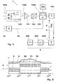
- the detector 1 shows schematically a battery-operated wireless movement or presence detector 1.
- the detector 1 comprises measuring means 100, 101, 102 and a control unit 103 for generating and evaluating a measurement signal 100b, with which the movement or presence 100a of an object can be detected.
- the detector 1 comprises an autonomous supply source 105 for at least temporarily powering at least one power-consuming component 100, 101, 102, 103, 104 of the detector 1.
- the object to be detected may be a person, an animal, a bicycle, a car o act.
- the motion detector 1 is, for example, a passive infrared detector 1 (PIR), but may also be an active infrared detector based on infrared reflection, an active ultrasonic detector based on ultrasonic reflection or Doppler effect, an acoustic sound detector, an active microwave detector or the like.
- PIR passive infrared detector 1
- 100 the widely used passive infrared detector comprising two pyroelectric crystals A, A ', which are opposed to each other Polarity are interconnected.
- a field effect transistor comprising drain D, collector and source S, which is capacitively coupled to ground GND
- the signal amplifier 101 in the A / D converter 102 converted into a digital signal and finally evaluated in the microcontroller 103.
- a separate installation of the detector 1 by the actuator 2 is required.
- the sensor part 1 should be able to be operated with a battery 105 and the switching command from the sensor 1 to the actuator 2 should be transmitted by a wireless connection 3.
- the detector 1 a transmitter 104 and the actuator 2, a receiver 204, which can operate on the basis of radio waves, microwaves, acoustic waves o. ⁇ .
- the actuator 2 comprises its own microcontroller 203 and a switch 200, in particular a relay or a semiconductor switch 200, for controlling a light source, a shutter, a fan, an air conditioning system, a heater or other electrical devices.
- a photosensitive element 5 is present, from which ambient light 5a is detected and a corresponding ambient light signal 5b is forwarded to the motion detector 1 and in particular its microcontroller 103.
- Conventional battery-operated motion detectors 1 then suppress the tripping command to the actuator 2 or the relay 2, without switching to a special power-saving mode.
- the actuation of the actuator 2 is dependent on the motion signal 100b of the motion detector 1 and the ambient light signal 5a of the element 5.
- the ambient light signal 5a is used directly to between the motion detector 1 in response to the ambient light signal 5b a mode of operation 7 for detection readiness and an energy saving mode 8 to reduce the power consumption I of the supply source 105 of the motion detector 1 switch.
- the switching occurs automatically and triggered by the ambient light signal 5b.
- the switching means 103b thus represent a control circuit 103b, which may be arranged inside or outside the control unit 103 and with the aid of which by switching between operating mode 7 and power saving mode 8, the battery life is extended.
- the control circuit switches as a function of the size of the ambient light signal and in no way reduces the measurement reliability of the motion detector 1.
- the control unit 103 comprises the switching means 103b and in particular the microcontroller 103.
- motion sensor 100, data acquisition part or signal processing unit 101, 102, evaluation electronics 103 need only be active for the personal identification and communication part 104 if a predefinable brightness, be it dark or light, is present in the environment. If this is not the case, z. B. the microcontroller 103 are switched to a low-power mode 8 and are awakened only once for the measurement of brightness, for example, once per second. The rest of the electronics 100-104 may remain off during this time.
- the switching means 103b comprise comparator means for comparing the ambient light signal 5b with a predefinable brightness threshold value 60; 61, 62 and computing means for determining the operating mode 7 or energy saving mode 8 in function of the comparison.
- switching means 103b activate the energy saving mode 8 when a light switch 200 is to be controlled by the motion detector 1 and the ambient light signal 5b is above the brightness threshold value 60; 61, 62 or if the motion detector 1 is to control an installation 200 which is to be activated in the case of ambient light 5a, in particular a sun blind or daytime activated or daylight-dependent ventilation, air conditioning or office installation, and the ambient light signal 5b below the brightness threshold value 60; 61, 62 is located.
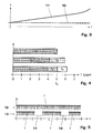
- FIG. 2 shows an exemplary embodiment of a motion detector 1 for activating a light switch 2. Shown is the brightness curve 6 as a function of the time of day t.
- a threshold value 60 in the morning is exceeded, the day energy-saving mode 8 is switched and the motion detector 1 is thus deactivated.
- the evening falls below the brightness threshold 60 is switched to the night operating mode 7 and the motion detector 1 is activated.
- a hysteresis is introduced in such a way that in the morning the threshold value 61, increased by a trigger, and in the evening the threshold value 62, reduced by a trigger, serves as a switching criterion.
- the autonomous power source 105 may be any battery power, including a rechargeable battery or a rechargeable battery.
- the battery 105 may also be arranged outside of the motion detector 1.
- the photosensitive member 5 may be a photocell, a photo-resistor (LDR), phototransistor or the like.
- the photosensitive element 5 is in the range of the motion detector 1 and / or an actuator 2 controlled by the motion detector 1. It may be arranged in particular in the motion detector 1 or optionally in the actuator 2 itself.
- a return communication 4 to the detector 1 may also be present.
- the return communication 4 is used to tell from the actuator 2 to the detector 1, how good the transmission connection works and to regulate the transmission power to an optimum level if necessary and in particular to lower.
- the invention also relates to a motion detection system comprising a motion detector 1 as described above and an actuator 2 controlled by the motion detector 1, as well as a device, an installation or a machine comprising such a motion detector 1.
- the invention relates to a scanning method for a motion detector 1, wherein at least one power-consuming component 100, 101, 102, 103, 104 of the motion detector 1 is at least temporarily fed by an autonomous power source 105, wherein the motion detector 1, a measurement signal 100b for detection the motion or presence 100a of an object and of a photosensitive element 5, an ambient light signal 5b for detecting ambient light 5a is generated, further depending on the ambient light signal 5b, the motion detector 1 between a mode of operation 7 for DetektionsrMft and a power saving mode 8 for reducing the power consumption of the I Power source 105 is switched.
- a mode of operation 7 for DetektionsrMft for Detektions
- the motion detector can be put into operating mode 7 or energy-saving mode 8 independently of the measuring signal 100b.
- the energy-saving mode can be activated by default.
- the ambient light 5a is measured in the region of the motion detector 1 and / or an actuator 2 controlled by the motion detector 1; this may be daylight 5a and / or artificial light 5a.
- a measurement of the ambient light 5a is initiated by a control unit 103 of the motion detector 1 and the resulting ambient light signal 5b is initiated with a brightness threshold value 60; 61, 62, which in particular is hysteresis-type and activated as a function of the comparison of the operating mode 7 or the energy-saving mode 8.
- the control unit 103 is switched to standby insofar that it is activated automatically and only as necessary for the repeated measurement of the ambient light 5a.
- the microcontroller 103 runs a clock, for example, the microcontroller 103 wakes every 1 s or 10 s and initiates measurement.
- the control unit 103 thus runs only in a minimal configuration which serves for periodic or repeated monitoring of the environment for brightness 5a and for occasional waking up of the entire motion detector 1.
- a light switch 200 is controlled by the motion detector 1 and activated on the basis of the comparison of the energy-saving mode 8 when the brightness threshold value 60; 61, 62 is exceeded by the ambient light 5a.
- the comparison is thus carried out so that the motion detector 1 is largely inactive in daylight and in the dark in detection readiness.
- the movement detector 1 can control an installation 200 to be activated in the case of ambient light 5a, in particular a sun-blind 200 or day-activated ventilation, air-conditioning or office installation, and be activated on the basis of the comparison of the energy-saving mode 8 if the brightness threshold value 60; 61, 62 is fallen below by ambient light 5a.
- a sampling rate f 1 , f 2 , f 3 can be reduced with a decreasing residual life of the supply source 105 (FIGS. 3, 4).
- a sampling rate f, 13 can be left unchanged and intermittent sampling gaps 14 can be permitted (FIG. 5).
- Fig. 3 shows the power consumption I of a data acquisition system 101-103 or microcontroller 103 as a function of the sampling rate or clock frequency f.
- the total power consumption I, 11 is composed of a base load 10 and a dependent of the sampling frequency f part.
- the base load 10 is composed of the power consumption of the microcontroller 103 in the sleep mode, the consumption of the amplifier 101 and the sensor 100 (if they can not be turned off) as well as leakage currents of other components.
- the frequency-dependent part increases substantially proportionally and at high frequencies f disproportionately to the frequency f.
- the power consumption I of a data acquisition system 101-103 e.g. of an analog-to-digital converter 102, are approximately halved when the sampling rate f is reduced by a factor of two.
- the relevant sampling rates f of the infrared motion detector 1 for the evaluation and detection of a person are in a frequency range between about 0.1 Hz and 10 Hz.
- Fig. 5 shows an alternative or supplementary scanning method in which a burst mode scan is performed.
- a signal is detected by equidistant or at least continuous scans 12.
- sampling may also be performed in a burst mode 13 by allowing sense or sampling gaps 14.
- the sampling rate f remains unchanged, but is temporarily suspended or interrupted.
- the burst mode 13 can basically be operated independently of a remaining service life of the battery 105.
- the power consumption I can be reduced the more, the longer the coverage gaps 14 are selected in burst mode 13.
- the penalty is that the traceability of the motion signal 100b becomes worse and, in essence, the response time is increased until movement 100a can be detected.
- a good compromise is when a dead-time 14 or sleep-mode 14 wake-time ratio is chosen so that people can not pass unguarded or unnoticed an area to be controlled.
- a dead time 14 or detection gap 14 of 100 ms to a few 100 ms is generally tolerable.
- the burst mode 13 can always allow for longer sampling intervals 14 with increasing battery life, so that the battery life remains intermittently available with ever lower availability for long periods of time.
- the scanning methods according to FIGS. 4 and 5 are freely combinable with the method according to the invention and in particular with each other. Overall, a minimum sampling rate over a minimum period should be ensured in any case for detecting moving persons, cyclists, cars o. ⁇ .
- the reduction of the sampling frequency f 1 , f 2 , f 3 and the admission of sampling gaps 14 will also be determined depending on a spatial area to be monitored, a field of view and in dependence of several motion detectors 1.
Abstract
Description
Die Erfindung bezieht sich auf das Gebiet autonom betriebener elektrischer Geräte und Installationen und insbesondere auf batteriebetriebene Geräte der Hausinstallationstechnik. Sie geht aus von einem Abtastverfahren, einem Bewegungsmelder, einem System und einer Installation gemäß Oberbegriff der unabhängigen Patentansprüche.The invention relates to the field of autonomously operated electrical equipment and installations, and more particularly to battery-operated domestic installation equipment. It is based on a scanning method, a motion detector, a system and an installation according to the preamble of the independent claims.
Bewegungsmelder sind Geräte, die Personen in einem möglichst definierten Bereich oder Raumwinkel erfassen. Sie werden vor allem in der Installationstechnik verwendet. Bevorzugt werden sie zur Steuerung von Lichtquellen, Ventilatoren, Heizungen oder anderen elektrischen Geräten eingesetzt. Bewegt sich eine Person auf einen Sensor zu, so wird über ein Relais oder einen Halbleiterschalter z. B. eine Lampe eingeschaltet. Die Sensoren basieren auf einem Infrarot-Detektor, der entsprechend der abgestrahlten Temperatur eines sich bewegenden Körpers ein Signal erzeugt. Typischerweise werden diese Geräte fest verdrahtet und am Niederspannungsversorgungsnetz betrieben.Motion detectors are devices that detect people in a defined area or solid angle. They are mainly used in the installation technology. Preferably, they are used to control light sources, fans, heaters or other electrical equipment. If a person moves towards a sensor, then a relay or a semiconductor switch z. B. turned on a lamp. The sensors are based on an infrared detector, which generates a signal according to the radiated temperature of a moving body. Typically, these devices are hard-wired and operated on the low-voltage power supply.
Aus der US-A-5 892 446 sind ein Abtastverfahren für einen Bewegungsmelder und ein Bewegungsmelder bekannt, wobei mindestens eine stromverbrauchende Komponente des Bewegungsmelders mindestens zeitweise von einer autonomen Speisequelle gespeist wird, wobei vom Bewegungsmelder ein Messsignal zur Detektion der Bewegung oder Anwesenheit eines Objekts und von einem lichtempfindlichen Element ein Umgebungslichtsignal zur Detektion von Umgebungslicht erzeugt wird und wobei in Abhängigkeit des Umgebungslichtsignals der Bewegungsmelder zwischen einem Betriebsmode für Detektionsbereitschaft und einem Energiesparmode zur Reduktion des Stromverbrauchs der Speisequelle umgeschaltet wird.From US-A-5 892 446 there are known a scanning method for a motion detector and a motion detector wherein at least one power consuming component of the motion detector is at least temporarily powered by an autonomous power source, the motion detector providing a measurement signal for detecting the movement or presence of an object and is generated by a photosensitive element, an ambient light signal for detecting ambient light and wherein depending on the ambient light signal, the motion detector between a Operating mode for detection readiness and an energy-saving mode for reducing the power consumption of the supply source is switched.
Im U. S. Pat. No. 4 982 176 wird ein Aussenbeleuchtungs- und Alarmsystem mit einem passiven Infrarot-Bewegungsmelder offenbart. Das System wird durch eine Batterie gespeist, die über Solarzellen nachladbar ist. Der Batteriebetrieb der Beleuchtung oder des Alarms wird von einer elektronischen Steuerung nur dann aktiviert, wenn der Bewegungsmelder ein bewegliches Objekt detektiert hat. Zudem kann eine Aktivierung des Systems bei Tag mit Hilfe eines Tageslichtdetektors verhindert werden. Maßnahmen zur Reduktion des Stromverbrauchs im Bewegungsmelder sind keine vorgesehen.In U.S. Pat. 4 982 176 discloses an outdoor lighting and alarm system with a passive infrared motion detector. The system is powered by a battery that is rechargeable via solar cells. The battery operation of the lighting or the alarm is activated by an electronic control only if the motion detector has detected a moving object. In addition, activation of the system during the day with the aid of a daylight detector can be prevented. Measures to reduce the power consumption in the motion detector are not provided.
In der EP 1 278 047 A 2 wird ein Abtastverfahren für Durchflussmessgeräte angegeben, bei dem eine Abtastrate in Abhängigkeit einer Restlebensdauer der Speisequelle verringert wird. Dadurch kann auf Kosten der Messgenauigkeit die Lebensdauer der Speisequelle erhöht werden.
In JP 102 46 662 A, Patent Abstract wird ein elektronisches Wassermeter offenbart, bei dem ein magnetischer Sensor vorhanden ist, dessen Abtastrate in Abhängigkeit des Sensorsignals angepasst wird. Zur Verringerung des Energieverbrauchs wird die Abtastrate erniedrigt, wenn das Sensorsignal stabil oder weitgehend unverändert bleibt, und erhöht, wenn Änderungen im Sensorsignal auftreten. Eine Reduktion des Energieverbrauchs in Abhängigkeit anderer Parameter und insbesondere einer Restlebensdauer der Speisequelle ist nicht vorgesehen.JP 102 46 662 A, patent abstract discloses an electronic water meter in which a magnetic sensor is present whose sampling rate is adjusted as a function of the sensor signal. To reduce power consumption, the sampling rate is lowered when the sensor signal remains stable or largely unchanged and increases as changes in the sensor signal occur. A reduction in energy consumption as a function of other parameters and in particular a residual life of the supply source is not provided.
In der WO 98/52061 wird ein Messgerät oder Gaszähler angegeben, bei dem der Batterieladezustand überwacht wird und der Zeitpunkt bestimmt wird, wann die Batterie ersetzt werden soll. Der Bestimmung der verbleibenden Batteriekapazität oder Restlebensdauer liegen u. a. zugrunde: eine Zählung der Betriebstage der Batterie seit deren Inbetriebnahme; eine Batterieselbstentladung; ein Stand-by Verbrauch des Messgeräts; eine Zählung, wie oft bestimmte Betriebsmodi des Messgeräts ausgeführt wurden; eine auf Statistik oder Erfahrungswerten basierende Extrapolation des mutmaßlichen zukünftigen Energieverbrauchs; sowie eine Sicherheitsmarge zur Überbrückung der Zeit zwischen Batteriealarm und tatsächlichem Ersatz der Batterie. Maßnahmen zur Verlängerung der Batterielebensdauer werden keine ergriffen.In WO 98/52061 a meter or gas meter is specified, in which the battery state of charge is monitored and the time is determined when the battery should be replaced. Determining the remaining battery capacity or Remaining service life is based inter alia on: a count of the operating days of the battery since its commissioning; a battery self-discharge; a stand-by consumption of the meter; a count of how often certain operating modes of the meter have been performed; a statistical or empirical extrapolation of the putative future energy consumption; and a safety margin to bridge the time between battery alarm and battery replacement. Measures to extend the battery life are not taken.
Aufgabe der vorliegenden Erfindung ist es, ein Verfahren und eine Vorrichtung zur Verlängerung der Funktionsdauer eines autonomen Bewegungsmelders anzugeben. Diese Aufgabe wird erfindungsgemäß durch die Merkmale der unabhängigen Ansprüche gelöst.The object of the present invention is to provide a method and a device for extending the service life of an autonomous motion detector. This object is achieved by the features of the independent claims.
In einem ersten aus dem Stand der Technik bekannten Aspekt besteht die Erfindung in einem Abtastverfahren.für einen Bewegungsmelder, wobei mindestens eine stromverbrauchende Komponente des Bewegungsmelders mindestens zeitweise von einer autonomen Speisequelle gespeist wird, wobei vom Bewegungsmelder ein Messsignal zur Detektion der Bewegung oder Anwesenheit eines Objekts und von einem lichtempfindlichen Element ein Umgebungslichtsignal zur Detektion von Umgebungslicht erzeugt wird, wobei in Abhängigkeit des Umgebungslichtsignals der Bewegungsmelder zwischen einem Betriebsmode für Detektionsbereitschaft und einem Energiesparmode zur Reduktion des Stromverbrauchs der Speisequelle umgeschaltet wird. Durch das Verfahren wird der Stromverbrauch eines Bewegungsmelders mit mindestens teilweise autonomer Stromversorgung reduziert, ohne dass die Messzuverlässigkeit des Bewegungsmelders eingeschränkt werden muss. Dies wird dadurch erreicht, dass der Bewegungsmelder oder mindestens eine stromverbrauchende Komponente des Bewegungsmelders nur dann aufgeweckt wird und damit der Bewegungsmelder in Messbereitschaft versetzt wird, wenn aufgrund des Umgebungslichtsignals feststeht, dass das Ergebnis der Bewegungs- oder Anwesenheitsmessung auch tatsächlich zur Ansteuerung des Aktuators verwendet werden soll.In a first aspect known from the prior art, the invention consists in a motion sensor, wherein at least one current-consuming component of the motion detector is at least temporarily fed by an autonomous supply source, wherein the motion detector is a measurement signal for detecting the movement or presence of an object and an ambient light signal for detecting ambient light is generated by a photosensitive element, wherein in dependence on the ambient light signal, the motion detector is switched between a mode of operation for detection readiness and a power saving mode for reducing the power consumption of the supply source. The method reduces the power consumption of a motion detector with at least partially autonomous power supply without having to restrict the measurement reliability of the motion detector. This is achieved by the motion detector or at least one current-consuming component of the motion detector is only woken up and thus the motion detector is put into measurement readiness, if it is clear from the ambient light signal that the result of the movement or presence measurement should actually be used to control the actuator.
Durch die im kennzeichnenden Teil des Patentanspruchs 1 angegebenen Abtastverfahren kann der Stromverbrauch des Bewegungsmelders noch weiter gesenkt werden.By the scanning method specified in the characterizing part of
Das Ausführungsbeispiel gemäß Anspruch 2a stellt sicher, dass die durch das Umgebungslichtsignal gesteuerte Stromsparschaltung übergeordnet über die Messsignalerfassung des Bewegungsmelders betrieben wird. Gemäß Anspruch 2b wird der Bewegungsmelder besonders stromsparend betrieben. Gemäß Anspruch 2c werden im Energiesparmode die wesentlichen oder alle stromverbrauchenden Komponenten ausgeschaltet und/oder auf Stand-By geschaltet.The exemplary embodiment according to claim 2a ensures that the power-saving circuit controlled by the ambient light signal is operated in a higher-order manner via the measuring signal detection of the motion detector. According to claim 2b, the motion detector is operated particularly energy-efficient. According to claim 2c, the essential or all power-consuming components are switched off and / or switched to stand-by in energy saving mode.
Das Ausführungsbeispiel gemäß Anspruch 3 hat den Vorteil, dass das Umgebungslichtsignal dort erfasst wird, wo ein Aktuator in Abhängigkeit einer Personen- oder Objekterfassung und eines natürlichen oder künstlichen Umgebungslichts gesteuert werden soll.The embodiment according to
Anspruch 4 betrifft ein Ausführungsbeispiel, bei dem die Überwachung des Umgebungslichts von der Kontrolleinheit des Bewegungsmelders selber gesteuert wird und die Überwachung von der Kontrolleinheit auch im Energiesparmode gewährleistet wird.
Das Ausführungsbeispiel gemäß Anspruch 5 hat den Vorteil, dass abhängig von der Art des zu steuernden Aktuators der Energiesparmode im Tagesbetrieb oder im Nachtbetrieb aktiviert werden kann.The embodiment according to
In einem weiteren Aspekt betrifft die Erfindung einen Bewegungsmelder, umfassend Messmittel und eine Kontrolleinheit zur Erzeugung und Auswertung eines Messsignals zur Detektion der Bewegung oder Anwesenheit eines Objekts sowie eine autonome Speisequelle zur mindestens zeitweisen Speisung mindestens einer stromverbrauchenden Komponente des Bewegungsmelders, wobei ein lichtempfindliches Element zur Erzeugung eines Umgebungslichtsignals in Abhängigkeit eines Umgebungslichts vorhanden ist, wobei ferner der Bewegungsmelder einen Betriebsmode für Detektionsbereitschaft und einen Energiesparmode zur Reduktion des Stromverbrauchs der Speisequelle aufweist und Umschaltmittel zum selbsttätigen Umschalten des Bewegungsmelders zwischen dem Betriebsmode und dem Energiesparmode in Abhängigkeit einer Größe des Umgebungslichtsignals vorhanden sind.In a further aspect, the invention relates to a motion detector comprising measuring means and a control unit for generating and evaluating a measurement signal for detecting the movement or presence of an object and an autonomous supply source for at least temporarily powering at least one current-consuming component of the motion detector, wherein a photosensitive element for generating an ambient light signal in response to an ambient light is present, further wherein the motion detector has a mode of operation for detection readiness and an energy saving mode for reducing the power consumption of the supply source and switching means for automatically switching the motion detector between the operating mode and the energy saving mode depending on a size of the ambient light signal are present.
Die Erfindung betrifft auch ein System umfassend einen Bewegungsmelder wie zuvor beschrieben und einen durch den Bewegungsmelder gesteuerten Aktuator oder ein Gerät, eine Installation oder eine Maschine umfassend einen solchen Bewegungsmelder.The invention also relates to a system comprising a motion detector as described above and an actuator controlled by the motion detector or a device, installation or machine comprising such a motion detector.
Weitere Ausführungen, Vorteile und Anwendungen der Erfindung ergeben sich aus abhängigen Ansprüchen sowie aus der nun folgenden Beschreibung und den Figuren.Further embodiments, advantages and applications of the invention will become apparent from the dependent claims and from the following description and the figures.
Es zeigen
- Fig. 1
- ein Blockdiagramm eines batteriebetriebenen Bewegungsmelders mit Funkanbindung an einen Aktuator;
- Fig. 2
- einen ersten Stromsparbetrieb des Bewegungsmelders mit einem alternierenden Tag- und Nachtbetriebsmode;
- Fig. 3
- einen Stromverbrauch des Bewegungsmelders in Funktion der Abtastrate seines Bewegungssensors;
- Fig. 4
- schematisch einen zweiten Stromsparbetrieb des Bewegungsmelders mit reduzierter Abtastrate; und
- Fig. 5
- schematisch einen dritten Stromsparbetrieb des Bewegungsmelders mit Zulassung von Abtastlücken.
- Fig. 1
- a block diagram of a battery powered motion detector with radio connection to an actuator;
- Fig. 2
- a first power saving operation of the motion detector with an alternating day and night operating mode;
- Fig. 3
- a power consumption of the motion detector in function of the sampling rate of its motion sensor;
- Fig. 4
- schematically a second power saving operation of the motion detector with a reduced sampling rate; and
- Fig. 5
- schematically a third power saving operation of the motion detector with permission of sampling gaps.
In den Figuren sind gleiche Teile mit gleichen Bezugszeichen versehen.In the figures, like parts are given the same reference numerals.
Fig. 1 zeigt schematisch einen batteriebetriebenen drahtlosen Bewegungs- oder Anwesenheitsmelder 1. Der Melder 1 umfasst Messmittel 100, 101, 102 und eine Kontrolleinheit 103 zur Erzeugung und Auswertung eines Messsignals 100b, mit dem die Bewegung oder Anwesenheit 100a eines Objekts erfassbar ist. Der Melder 1 umfasst eine autonome Speisequelle 105 zur mindestens zeitweisen Speisung mindestens einer stromverbrauchenden Komponente 100, 101, 102, 103, 104 des Melders 1. Bei dem zu erfassenden Objekt kann es sich um eine Person, ein Tier, ein Fahrrad, ein PKW o. ä. handeln. Der Bewegungsmelder 1 ist beispielsweise ein Passiv-Infrarotdetektor 1 (PIR), kann aber auch ein aktiver Infrarotdetektor basierend auf Infrarotreflektion, ein aktiver Ultraschalldetektor basierend auf Ultraschallreflektion oder Dopplereffekt, ein akustischer Schalldetektor, ein aktiver Mikrowellendetektor o. ä. sein. Mit 100 ist der weit verbreitete Passiv-Infrarotdetektor bezeichnet, der zwei pyroelektrische Kristalle A, A' umfasst, die mit entgegengesetzter Polarität zusammengeschaltet sind. Die Kristalle A, A' geben aufgrund der Wärmestrahlung 100a eines bewegten Wärmeobjekts ein charakteristisches elektrisches Messsignal 100b ab, dass mit einem Feldeffekttransistor, umfassend Drain D, Kollektor und Source S, die kapazitiv an Erde GND gekoppelt ist, vorverstärkt, im Signalverstärker 101 weiterverstärkt, im A/D-Wandler 102 in ein digitales Signal gewandelt und schliesslich im Mikrokontroller 103 ausgewertet wird. Insbesondere bei Retrofit-Anwendungen, bei abgelegenen Installationsorten ohne direkten Netzzugang oder bei Systemen, die eine Mehrzahl von Sensoren und Aktuatoren 2 umfassen, wird eine getrennte Installation des Detektors 1 vom Aktuator 2 gefordert. Dabei soll der Sensorteil 1 mit einer Batterie 105 betrieben werden können und der Schaltbefehl vom Sensor 1 zum Aktuator 2 soll durch eine drahtlose Verbindung 3 übermittelt werden. Hierfür weist der Melder 1 einen Sender 104 und der Aktuator 2 einen Empfänger 204 auf, die auf der Basis von Radiowellen, Mikrowellen, akustischen Wellen o. ä. funktionieren können. Ferner umfasst der Aktuator 2 einen eigenen Mikrokontroller 203 und einen Schalter 200, insbesondere ein Relais oder einen Halbleiterschalter 200, zur Steuerung einer Lichtquelle, einer Jalousie, eines Ventilators, einer Klimaanlage, einer Heizung oder anderer elektrischer Geräte.1 shows schematically a battery-operated wireless movement or
Zusätzlich ist ein lichtempfindliches Element 5 vorhanden, von dem Umgebungslicht 5a detektiert und ein entsprechendes Umgebungslichtsignal 5b an den Bewegungsmelder 1 und insbesondere seinen Mikrokontroller 103 weitergeleitet wird. Herkömmliche batteriebetriebene Bewegungsmelder 1 unterdrücken dann das Auslösekommando an den Aktuator 2 oder das Relais 2, ohne in einen speziell stromsparenden Modus zu wechseln. Im bekannten Stand der Technik erfolgt also die Ansteuerung des Aktuators 2 abhängig vom Bewegungssignal 100b des Bewegungsmelders 1 und vom Umgebungslichtsignal 5a des Elements 5. Erfindungsgemäss wird hingegen das Umgebungslichtsignal 5a direkt dazu verwendet, den Bewegungsmelder 1 in Abhängigkeit des Umgebungslichtsignals 5b zwischen einem Betriebsmode 7 für Detektionsbereitschaft und einem Energiesparmode 8 zur Reduktion des Stromverbrauchs I der Speisequelle 105 des Bewegungsmelders 1 umzuschalten. Das Umschalten erfolgt selbsttätig und getriggert durch das Umgebungslichtsignal 5b. Die Umschaltmittel 103b stellen also eine Steuerschaltung 103b dar, die innerhalb oder auch ausserhalb der Kontrolleinheit 103 angeordnet sein kann und mit deren Hilfe durch Umschalten zwischen Betriebsmode 7 und Stromsparmode 8 die Batterielebensdauer verlängerbar ist. Dabei schaltet die Steuerschaltung in Abhängigkeit der Grösse des Umgebungslichtsignals und vermindert in keiner Weise die Messzuverlässigkeit des Bewegungsmelders 1.In addition, a
Im allgemeinen umfasst die Kontrolleinheit 103 die Umschaltmittel 103b und insbesondere den Mikrokontroller 103. Vorzugsweise ist im Energiesparmode 8 jedes Messmittel 100, 101, 102 ausgeschaltet oder auf Stand-by geschaltet und die Kontrolleinheit 103 ist insoweit auf Stand-by geschaltet, dass sie für eine wiederholte Messung des Umgebungslichts 5a selbsttätig und nur soweit nötig aktivierbar ist. Insbesondere brauchen Bewegungssensor 100, Datenerfassungsteil oder Signalverarbeitungseinheit 101, 102, Auswertelektronik 103 für die Personenidentifikation und Kommunikationsteil 104 nur dann aktiv zu sein, falls in der Umgebung eine vorgebbare Helligkeit, sei es dunkel oder hell, vorhanden ist. Ist dies nicht der Fall, kann z. B. der Mikrokontroller 103 in einen Low-Power Mode 8 geschaltet werden und nur für die Messung der Helligkeit beispielsweise einmal pro Sekunde aufgeweckt werden. Der Rest der Elektronik 100-104 kann während dieser Zeit abgeschaltet bleiben.In general, the
Mit Vorteil umfassen die Umschaltmittel 103b Komparatormittel zum Vergleich des Umgebungslichtsignals 5b mit einem vorgebbaren Helligkeitsschwellwert 60; 61, 62 und Rechenmittel zur Bestimmung des Betriebsmodes 7 oder Energiesparmodes 8 in Funktion des Vergleichs. Bevorzugt aktivieren Umschaltmittel 103b den Energiesparmode 8 dann, wenn durch den Bewegungsmelder 1 ein Lichtschalter 200 gesteuert werden soll und das Umgebungslichtsignal 5b über dem Helligkeitsschwellwert 60; 61, 62 liegt oder wenn durch den Bewegungsmelder 1 eine bei Umgebungslicht 5a zu aktivierende Installation 200, insbesondere eine Sonnenjalousie oder tagsüber aktivierbare oder tageslichtabhängige Ventilation, Klimaanlage oder Büroinstallation, gesteuert werden soll und das Umgebungslichtsignal 5b unter dem Helligkeitsschwellwert 60; 61, 62 liegt.Advantageously, the switching means 103b comprise comparator means for comparing the ambient
Fig. 2 zeigt ein Ausführungsbeispiel für einen Bewegungsmelder 1 zur Aktivierung eines Lichtschalters 2. Dargestellt ist der Helligkeitsverlauf 6 als Funktion der Tageszeit t. Bei Überschreiten eines Schwellwerts 60 am Morgen wird in den Tages-Energiesparmode 8 geschaltet und damit der Bewegungsmelder 1 deaktiviert. Am Abend bei Unterschreiten des Helligkeitsschwellwerts 60 wird in den Nacht-Betriebsmode 7 geschaltet und der Bewegungsmelder 1 aktiviert. Um während der Übergangsphasen Hin- und Herschalten zu vermeiden, wird eine Hysterese derart eingeführt, dass am Morgen der Schwellwert 61, erhöht um einen Trigger, und am Abend der Schwellwert 62, erniedrigt um einen Trigger, als Umschaltkriterium dient. Über das Jahresmittel kann so ein batteriebetriebener Bewegungsmelder 1 ca. die Hälft der Zeit im Tages-Sparmodus 8 betrieben werden. Die Batterielebensdauer lässt sich dadurch drastisch verlängern. Hierzu ein Zahlenbeispiel: Stromverbrauch im Nacht-Betriebsmodus 7: 27 mA; Stromverbrauch im Tages-Energiesparmoduls 8: 4 mA; durchschnittlicher Stromverbrauch 15,5 mA bei hälftigem Tag/Nachtbetrieb. Die Batterielebensdauer verlängert sich um fast einen Faktor zwei, ohne Berücksichtigung von zusätzlicher Selbstentladung und Alterung der Batterie 105.FIG. 2 shows an exemplary embodiment of a
Die autonome Speisequelle 105 kann eine beliebige Batteriespeisung, auch eine aufladbare Batterie oder ein Akkumulator sein. Die Batterie 105 kann auch ausserhalb des Bewegungsmelders 1 angeordnet sein. Das lichtempfindliche Element 5 kann eine Photozelle, ein Photowiderstand (LDR=light dependent resistor), Phototransistor o. ä. sein. Mit Vorteil ist das lichtempfindliche Element 5 im Bereich des Bewegungsmelders 1 und/oder eines vom Bewegungsmelder 1 gesteuerten Aktuators 2 angeordnet. Es kann insbesondere im Bewegungsmelder 1 oder gegebenenfalls im Aktuator 2 selber angeordnet sein.The
Gemäss Fig. 1 kann bei drahtloser Kommunikation zwischen Melder 1 und Aktuator 2 neben der Hinkommunikation 3 zur Befehlsübermittlung an den Aktuator 2 auch eine Rückkommunikation 4 zum Melder 1 vorhanden sein. Die Rückkommunikation 4 dient dazu, um vom Aktuator 2 an den Melder 1 mitzuteilen, wie gute die Sendeverbindung funktioniert und um bei Bedarf die Sendeleistung auf ein optimales Niveau einzupegeln und insbesondere abzusenken.According to FIG. 1, in the case of wireless communication between the
Gegenstand der Erfindung ist auch ein System zur Bewegungsmeldung, umfassend einen Bewegungsmelder 1 wie zuvor beschrieben und einen durch den Bewegungsmelder 1 gesteuerten Aktuator 2, ebenso ein Gerät, eine Installation oder eine Maschine, umfassend einen solchen Bewegungsmelder 1.The invention also relates to a motion detection system comprising a
In einem weiteren Aspekt betrifft die Erfindung ein Abtastverfahren für einen Bewegungsmelder 1, wobei mindestens eine stromverbrauchende Komponente 100, 101, 102, 103, 104 des Bewegungsmelders 1 mindestens zeitweise von einer autonomen Speisequelle 105 gespeist wird, wobei vom Bewegungsmelder 1 ein Messsignal 100b zur Detektion der Bewegung oder Anwesenheit 100a eines Objekts und von einem lichtempfindlichen Element 5 ein Umgebungslichtsignal 5b zur Detektion von Umgebungslicht 5a erzeugt wird, wobei ferner in Abhängigkeit des Umgebungslichtsignals 5b der Bewegungsmelder 1 zwischen einem Betriebsmode 7 für Detektionsbereitschäft und einem Energiesparmode 8 zur Reduktion des Stromverbrauchs I der Speisequelle 105 umgeschaltet wird. Hierzu im folgenden einige Ausführungsbeispiele.In another aspect, the invention relates to a scanning method for a
Der Bewegungsmelder kann unabhängig vom Messsignal 100b in den Betriebsmode 7 oder Energiesparmode 8 versetzt werden. Der Energiesparmode kann defaultmässig aktiviert werden. Insbesondere wird im Energiesparmode 8 mindestens eine der mindestens einen stromverbrauchenden Komponente 100, 101, 102, 103, 104 des Bewegungsmelders 1, insbesondere jede der stromverbrauchenden Komponenten 100, 101, 102, 103, 104, ausgeschaltet oder auf Stand-by geschaltet. Bevorzugt wird das Umgebungslicht 5a im Bereich des Bewegungsmelders 1 und/oder eines vom Bewegungsmelder 1 gesteuerten Aktuators 2 gemessen; es kann sich dabei um Tageslicht 5a und/oder Kunstlicht 5a handeln.The motion detector can be put into
Bevorzugt wird von einer Kontrolleinheit 103 des Bewegungsmelders 1 wiederholt eine Messung des Umgebungslichts 5a initiiert und das resultierende Umgebungslichtsignal 5b mit einem Helligkeitsschwellwert 60; 61, 62 verglichen, der insbesondere hysteresebehaftet ist und in Abhängigkeit des Vergleichs der Betriebsmode 7 oder der Energiesparmode 8 aktiviert. Im Energiesparmode 8 wird die Kontrolleinheit 103 insoweit auf Stand-by geschaltet, dass sie selbsttätig und nur soweit nötig für die wiederholte Messung des Umgebungslichts 5a aktiviert wird. Im Mikrokontroller 103 läuft eine Uhr, die beispielsweise alle 1 s oder 10 s den Mikrokontroller 103 weckt und Messung initiiert. Im Energiesparmode 8 läuft also die Kontrolleinheit 103 nur noch in einer Minimalkonfiguration, die zur periodischen oder wiederholten Überwachung der Umgebung auf Helligkeit 5a und zum gelegentlichen Aufwecken des gesamten Bewegungsmelders 1 dient.Preferably, a measurement of the
Im Ausführungsbeispiel gemäss Fig. 2 wird vom Bewegungsmelder 1 ein Lichtschalter 200 gesteuert und aufgrund des Vergleichs der Energiesparmode 8 aktiviert, wenn der Helligkeitsschwellwert 60; 61, 62 vom Umgebungslicht 5a überschritten wird. Der Vergleich wird also so ausgeführt, dass der Bewegungsmelder 1 bei Tageslicht weitgehend inaktiv und bei Dunkelheit in Detektionsbereitschaft ist. Alternativ kann vom Bewegungsmelder 1 eine bei Umgebungslicht 5a zu aktivierende Installation 200, insbesondere eine Sonnenjalousie 200 oder tagsüber aktivierbare Ventilation, Klimaanlage oder Büroinstallation, gesteuert werden und aufgrund des Vergleichs der Energiesparmode 8 aktiviert werden, wenn der Helligkeitsschwellwert 60; 61, 62 vom Umgebungslicht 5a unterschritten wird.In the embodiment according to FIG. 2, a
Zusätzlich kann zur Reduktion des Stromverbrauchs I der Speisequelle 105 eine Abtastrate f1, f2, f3 mit einer abnehmenden Restlebensdauer der Speisequelle 105 reduziert werden (Fig. 3, 4). Alternativ oder ergänzend können eine Abtastrate f, 13 unverändert belassen und intermittierende Abtastlücken 14 zugelassen werden (Fig. 5).In addition, to reduce the power consumption I of the
Im Detail zeigt Fig. 3 den Stromverbrauch I eines Datenerfassungssystems 101-103 oder Mikrokontrollers 103 als Funktion der Abtastrate oder Taktfrequenz f. Der Gesamtstromverbrauch I, 11 setzt sich zusammen aus einer Grundlast 10 und einem von der Abtastfrequenz f abhängigen Teil. Die Grundlast 10 setzt sich aus dem Stromverbrauch des Mikrokontrollers 103 im Sleep-Mode, dem Verbrauch des Verstärkers 101 und des Sensors 100 (falls diese nicht ausgeschaltet werden können) sowie aus Leckströmen anderer Komponenten zusammen. Der frequenzabhängige Teil nimmt im wesentlichen proportional und bei hohen Frequenzen f überproportional zur Frequenz f zu. So kann der Stromverbrauch I eines Datenerfassungssystems 101-103, z.B. eines Analog/Digital-Wandlers 102, annähernd halbiert werden, wenn die Abtastrate f um den Faktor zwei reduziert wird.In detail, Fig. 3 shows the power consumption I of a data acquisition system 101-103 or
Die relevanten Abtastraten f des Infrarot-Bewegungsmelders 1 für die Auswertung und Detektion einer Person liegen in einem Frequenzbereich zwischen ca. 0,1 Hz und 10 Hz. Ein Erfassungssystem 1 muss also nach Theorie mit mindestens der doppelten Abtastrate, d. h. mit mindestens 20 Hz, betrieben werden. Für eine optimale Auswertung wird hier sogar mit 75 Hz gearbeitet. Dies erhöht die Zuverlässigkeit der Bewegungsdetektion durch den Bewegungsmelder 1. Neigt sich jedoch die Lebensdauer der Batterie 105 zuende, so kann es wichtiger sein, eine verlängerte Betriebsbereitschaft auch auf Kosten einer reduzierte Zuverlässigkeit bei der Detektion von Personen zu gewährleisten. Fig. 4 zeigt ein Beispiel, bei dem mit einer herkömmlichen Abtastrate von f1=75 Hz eine prognostizierte Batterielebensdauer TE von 5 Jahre erreicht wird. Wird nach 4 Jahren die Abtastrate von f1=75 Hz auf f2=60 Hz verringert, so verlängert sich die Lebensdauer auf knapp 6 Jahre, und, bei nochmaliger Reduktion auf f3=45 Hz, auf über 6 Jahre. Das System 1 kann also noch über eine längere Zeit mit einer relativ geringfügig reduzierten Detektionszuverlässigkeit betrieben werden, bis die Kapazität der Batterie 105 ganz aufgebraucht ist.The relevant sampling rates f of the
Fig. 5 zeigt ein alternatives oder ergänzendes Abtastverfahren, bei dem eine Abtastung im Burst-Mode durchgeführt wird. In der Regel wird ein Signal durch äquidistante oder zumindest kontinuierliche Abtastungen 12 erfasst. Falls der Stromverbrauch I eines Systems 1 jedoch reduziert werden soll, so kann die Abtastung auch in einem Burst-Mode 13 durchgeführt werden, indem Erfassungs- oder Abtastlücken 14 zugelassen werden. Die Abtastrate f bleibt dabei unverändert, wird jedoch zeitweise ausgesetzt oder unterbrochen. Der Burst-Mode 13 kann grundsätzlich unabhängig von einer Restlebensdauer der Batterie 105 betrieben werden.Fig. 5 shows an alternative or supplementary scanning method in which a burst mode scan is performed. As a rule, a signal is detected by equidistant or at least
Der Stromverbrauch I lässt sich um so stärker reduzieren, je länger die Erfassungslücken 14 im Burst-Mode 13 gewählt werden. Die Einbusse besteht darin, dass die Rückverfolgbarkeit des Bewegungssignals 100b schlechter wird und hauptsächlich die Reaktions- oder Ansprechzeit verlängert wird, bis eine Bewegung 100a detektiert werden kann. Ein guter Kompromiss liegt vor, wenn ein Verhältnis Totzeit 14 oder Sleep-Mode 14 zu Wachzeit so gewählt wird, dass Personen nicht unbewacht oder unbeachtet einen zu kontrollierenden Bereich passieren können. Hierfür ist eine Totzeit 14 oder Erfassungslücke 14 von 100 ms bis ein paar 100 ms im allgemeinen tolerabel. Der Burst-Mode 13 kann jedoch auch mit zunehmender Batterielebensdauer immer längere Abtastlücken 14 zulassen, so dass die Batterielebensdauer bei immer geringerer Verfügbarkeit noch über lange Zeiträume intermittierend verfügbar bleibt.The power consumption I can be reduced the more, the longer the
Die Abtastverfahren gemäss Fig. 4 und 5 sind frei mit dem erfindungsgemässen Verfahren und insbesondere miteinander kombinierbar. Insgesamt soll in jedem Fall zum Erkennen bewegter Personen, Velofahrer, Autos o. ä. eine minimale Abtastrate über einen minimalen Zeitraum gewährleistet sein. Die Absenkung der Abtastfrequenz f1, f2, f3 und die Zulassung von Abtastlücken 14 wird auch in Abhängigkeit eines zu überwachenden räumlichen Bereichs, eines Blickfelds und in Abhängigkeit mehrerer Bewegungsmelder 1 festzulegen sein.The scanning methods according to FIGS. 4 and 5 are freely combinable with the method according to the invention and in particular with each other. Overall, a minimum sampling rate over a minimum period should be ensured in any case for detecting moving persons, cyclists, cars o. Ä. The reduction of the sampling frequency f 1 , f 2 , f 3 and the admission of
- 11
- Autonomer BewegungsmelderAutonomous motion detector
- 100100
- Bewegungssensor, pyroelektrischer Detektor, Passiv-Infrarotdetektor (PIR)Motion sensor, pyroelectric detector, passive infrared detector (PIR)
- 100a100a
- Bewegungssignal, Anwesenheitssignal, WärmestrahlungMotion signal, presence signal, heat radiation
- 100b100b
- Messsignalmeasuring signal
- 101101
- Signalverstärkersignal amplifier
- 102102
- A/D-WandlerA / D converter
- 103103
- Kontrolleinheit, Mikrokontroller, µC, MikroprozessorControl unit, microcontroller, μC, microprocessor
- 103b103b
- Umschaltmittelswitching
- 104104
- Kommunikationsteil, Sender, TransceiverCommunication part, transmitter, transceiver
- 105105
- autonome Speisequelle, Batterieautonomous power source, battery
- 22
- Aktuatoractuator
- 200200
- Lichtschalter, JalousiesteuerungLight switch, blind control
- 203203
- Kontrolleinheit, Mikrokontroller, µC, MikroprozessorControl unit, microcontroller, μC, microprocessor
- 204204
- Kommunikationsteil, Empfänger, TransceiverCommunication part, receiver, transceiver
- 33
- Hinkommunikation, BefehlsrichtungHinkommunikation, command direction
- 44
- Rückkommunikationrear communication
- 55
- lichtempfindliches Element, Photowiderstand, Phototransistorphotosensitive element, photoresistor, phototransistor
- 5a5a
- Umgebungslicht, Tageslicht, KunstlichtAmbient light, daylight, artificial light
- 5b5b
- UmgebungslichtsignalAmbient light signal
- 66
- Helligkeitsverlaufbrightness curve
- 6060
- Schwellwert für Helligkeit, TriggerThreshold for brightness, trigger
- 6161
- Helligkeitsschwellwert plus HystereseBrightness threshold plus hysteresis
- 6262
- Helligkeitsschwellwert minus HystereseBrightness threshold minus hysteresis
- 77
- Betriebsmode, Nacht-BetriebsmodusOperating mode, night operating mode
- 88th
- Energiesparmode, Tag-BetriebsmodusEnergy saving mode, day operating mode
- 99
- Stromverbrauch, EnergieverbrauchPower consumption, energy consumption
- 1010
- StromverbrauchsgrundlastPower consumption baseload
- 1111
- GesamtstromverbrauchTotal power consumption
- 1212
- Kontinuierliche AbtastungContinuous scanning
- 1313
- intermittierende (Burst-Mode) Abtastungintermittent (burst-mode) sampling
- 1414
- Abtastlückensampling gaps
- A, A'A, A '
- pyroelektrische Kristallepyroelectric crystals
- A/DA / D
- analog/digitalanalog / digital
- DD
- Draindrain
- SS
- Sourcesource
- GNDGND
- Ground, ErdungGround, grounding
- f,f1,f2,f3 f, f 1 , f 2 , f 3
- Abtastrate, TaktfrequenzSampling rate, clock frequency
- II
- Stromverbrauchpower consumption
- tt
- Tageszeit, UhrzeitTime of day, time
- TT
- Batterielebensdauer (in Jahren)Battery life (in years)
- TE T E
- prognostizierte Batterielebensdauerpredicted battery life
Claims (13)
- A scanning method for a motion detector (1), with at least one current-consuming component (100, 101, 102, 103, 104) of the motion detector (1) being supplied at least temporarily by an autonomous power source (105), with the motion detector (1) generating a measuring signal (100b) for detecting the motion or presence (100a) of an object and an ambient light signal (5b) being generated by a light-sensitive element (5) for the detection of ambient light (5a), and with the motion detector (1) being changed over between an operating mode (7) for detection stand-by and an energy-saving mode (8) for the reduction of power consumption (I) of the power source (105) depending on the ambient light signal (5b), characterized in that for reducing the power consumption during the operating mode (I) of the power source (105)a) a scanning rate (f1, f2, f3) is reduced with decreasing residual life of the power source (105) and/orb) a scanning rate (f, 13) is left unchanged and intermittent scanning gaps (14) are permitted.
- A scanning method according to claim 1, characterized in thata) the motion detector (1) is placed irrespective of the measuring signal (100b) into the operating mode (7) or energy-saving mode (8) and/orb) the energy-saving mode is activated by default and/orc) in the energy-saving mode (8) at least one of the at least one current-consuming components (100, 101, 102, 103, 104) of the motion detector (1), especially each of the current-consuming components (100, 101, 102, 103, 104), is switched off or is switched to stand-by.
- A scanning method according to one of the preceding claims, characterized in thata) the ambient light (5a) is measured in the area of the motion detector (1) and/or an actuator (2) controlled by the motion detector (1) and/orb) the ambient light (5a) is daylight and/or artificial light.
- A scanning method according to one of the preceding claims, characterized in thata) a measurement of the ambient light (5a) is initiated repeatedly by a checking unit (103) of the motion detector (1) and the resulting ambient light signal (5b) is compared with a brightness threshold value (60; 61, 62) which is especially linked by hysteresis,b) the operating mode (7) or the energy-saving mode (8) is activated depending on the comparison,c) the checking unit (103) is switched to stand-by in the energy-saving mode (8) to the extent that it can be activated automatically and only to the extent as is necessary for the repeated measurement of the ambient light (5a).
- A scanning method according to claim 4, characterized in thata) a light switch (200) is controlled by the motion detector (1) and the energy-saving mode (8) is activated on the basis of the comparison when the brightness threshold value (60; 61, 62) is exceeded by the ambient light (5a) orb) the motion detector (1) controls an installation (200) to be activated at ambient light (5a), especially blinds (200) or ventilation to be activated during the day, an air-conditioning system or office installation, and the energy-saving mode (8) is activated as a result of the comparison when the ambient light (5a) falls below the brightness threshold value (60; 61, 62).
- A motion detector (1), comprising measuring means (100, 101, 102) and a checking unit (103) for generating and evaluating a measuring signal (100b) for detecting the movement or presence (100a) of an object and an autonomous power source (105) for powering at least temporarily at least one current-consuming component (100, 101, 102, 103, 104) of the motion detector (1), with further a light-sensitive element (5) being present for generating an ambient light signal (5a) depending on an ambient light (5a), and witha) the motion detector (1) having an operating mode (7) for detection readiness and an energy-saving mode (8) for the reduction of the power consumption (1) of the power source (105) andb) changeover means (1 03b) being present for automatic changeover of the motion detector (1) between the operating mode (7) and the energy-saving mode (8) depending on a variable of the ambient light signal (5b), characterized in that for reduction of the power consumption (I) of the power source (105) during the operating modec) a scanning rate (f1, f2, f3) is reduced with decreasing residual life of the power source (105) and/ord) a scanning rate (f, 13) is left unchanged and intermittent scanning gaps (14) are permitted.
- A motion detector (1) according to claim 6, characterized in thata) in the energy-saving mode (8) every measuring means (100, 101, 102) is switched off or switched to stand-by and the checking unit (103) is switched to stand-by to such an extent that it can be activated automatically and only to the extent as is necessary for the repeated measurement of the ambient light (5a) and/orb) the checking unit (103) comprises the changeover means (103b) and is especially a microcontroller (103).
- A motion detector (1) according to one of the claims 6 to 7, characterized in thata) the changeover means (103b) comprise comparator means for comparing the ambient light signal (5b) with a predeterminable brightness threshold value (60; 61, 62) andb) the changeover means (103b) comprise computing means for determining the operating mode (7) or the energy-saving mode (8) as a function of the comparison.
- A motion detector (1) according to claim 8, characterized in that the changeover means (103b) activate the energy-saving mode (8) whena) a light switch (200) is to be controlled by the motion detector (1) and the ambient light signal (5b) lies above the brightness threshold value (60; 61, 62) orb) the motion detector (1) controls an installation (200) to be activated at ambient light (5a), especially blinds (200) or ventilation to be activated during the day, an air-conditioning system or office installation, and the ambient light signal (5b) lies beneath the brightness threshold value (60; 61, 62).
- A motion detector (1) according to one of the claims 6 to 9, characterized in thata) the measuring means (100, 101, 102) comprise a motion sensor (100), a signal processing unit (101, 102), especially a signal amplifier (101) and an analog-to-digital converter (102), and communication means (104) for triggering an actuator (2), andb) especially that the motion sensor (100) is configured for detecting humans, animals and/or vehicles and is preferably a passive infrared detector (1).
- A motion detector (1) according to one of the claims 6 to 10, characterized in thata) the power source (105) is a battery source (105) of the motion detector (1), especially a rechargeable battery, and/orb) the light-sensitive element (5) is arranged in the area of the motion detector (1) and/or an actuator (2) controlled by the motion detector (1) and/orc) means are present for wireless feedback communication (4) from the actuator (2) to the motion detector (1) and for adjustment of a transmitter power of the motion detector (1) to a necessary output level.
- A system for motion detection, comprising a motion detector (1) according to one of the claims 6 to 11 and an actuator (2) controlled by the motion detector (1).
- A device, installation or machine, comprising a motion detector (1) according to one of the claims 6 to 11.
Applications Claiming Priority (2)
| Application Number | Priority Date | Filing Date | Title |
|---|---|---|---|
| DE10356071 | 2003-12-01 | ||
| DE10356071A DE10356071A1 (en) | 2003-12-01 | 2003-12-01 | Method and device for reducing power consumption in battery-powered motion detectors |
Publications (2)
| Publication Number | Publication Date |
|---|---|
| EP1538579A1 EP1538579A1 (en) | 2005-06-08 |
| EP1538579B1 true EP1538579B1 (en) | 2006-09-27 |
Family
ID=34442381
Family Applications (1)
| Application Number | Title | Priority Date | Filing Date |
|---|---|---|---|
| EP04405734A Active EP1538579B1 (en) | 2003-12-01 | 2004-11-25 | Method and device for power saving in battery driven movement detectors. |
Country Status (3)
| Country | Link |
|---|---|
| EP (1) | EP1538579B1 (en) |
| AT (1) | ATE341058T1 (en) |
| DE (2) | DE10356071A1 (en) |
Families Citing this family (10)
| Publication number | Priority date | Publication date | Assignee | Title |
|---|---|---|---|---|
| DE102005042568B3 (en) * | 2005-09-08 | 2007-01-04 | Abb Research Ltd. | Radio linked motion detector has several double sided sensor circuit boards with complete ground plane and infrared sensor and amplifier on opposite sides |
| GB0616282D0 (en) * | 2006-08-16 | 2006-09-27 | Circuitree Ltd | Context Monitoring For Remote Sensor Platform |
| DE102008004419A1 (en) * | 2008-01-14 | 2009-07-16 | Elmos Semiconductor Ag | Controllable lighting device i.e. garden path lamp, for illuminating outdoor area, has sensor staying in operative connection with timer, and control of illuminant provided by circuit that is coupled with regulating or switching device |
| DE102008004420A1 (en) * | 2008-01-14 | 2009-07-16 | Elmos Semiconductor Ag | Controllable lighting system i.e. wall socket lamp, for illuminating outdoor area, has circuit providing control of illuminant and control of luminous period and luminous intensity, and sensor-active region assigned to optical sensor |
| DE102008057042B4 (en) * | 2008-11-12 | 2013-03-28 | Waldemar Stach | Energy-saving sensor circuit |
| US8665090B2 (en) * | 2009-01-26 | 2014-03-04 | Lutron Electronics Co., Inc. | Multi-modal load control system having occupancy sensing |
| BRPI1009039B1 (en) * | 2009-06-04 | 2019-08-06 | Philips Lighting Holding B.V. | Wireless Light Sense, Method of Operating a Wireless Light Sense, and Lighting System |
| WO2017171962A2 (en) * | 2016-01-11 | 2017-10-05 | Carrier Corporation | Infrared presence detector system |
| DE102016124796A1 (en) * | 2016-12-19 | 2018-06-21 | Endress+Hauser Conducta Gmbh+Co. Kg | Sensor head module for continuous automated data acquisition |
| CN114166356B (en) * | 2021-12-06 | 2024-02-13 | 普联技术有限公司 | PIR threshold adjustment method, PIR threshold adjustment system and monitoring device |
Family Cites Families (6)
| Publication number | Priority date | Publication date | Assignee | Title |
|---|---|---|---|---|
| US4890093A (en) * | 1988-10-27 | 1989-12-26 | Schlage Lock Company | Solar powered proximity triggered light |
| US5128654A (en) * | 1990-02-23 | 1992-07-07 | Lightolier Incorporated | Preset light controller including infrared sensor operable in multiple modes |
| US5973594A (en) * | 1995-03-29 | 1999-10-26 | Hubbell Incorporated | Multiple optical designs for a multifunction sensor |
| US5892446A (en) * | 1997-03-10 | 1999-04-06 | Reich; Lee A. | Wild animal deterrent device |
| DE19814591A1 (en) * | 1998-04-01 | 1999-10-07 | Merten Gmbh & Co Kg Geb | Method and presence detector for controlling a lighting device |
| DE19913841A1 (en) * | 1999-03-27 | 2000-09-28 | Hansjoerg Klein | System to protect boats, holiday homes, kiosks, churches, museums or galleries; has hidden unit with movement sensor and camera and remote control receiver with monitor to display images |
-
2003
- 2003-12-01 DE DE10356071A patent/DE10356071A1/en not_active Withdrawn
-
2004
- 2004-11-25 DE DE502004001582T patent/DE502004001582D1/en active Active
- 2004-11-25 AT AT04405734T patent/ATE341058T1/en not_active IP Right Cessation
- 2004-11-25 EP EP04405734A patent/EP1538579B1/en active Active
Also Published As
| Publication number | Publication date |
|---|---|
| DE10356071A1 (en) | 2005-06-23 |
| EP1538579A1 (en) | 2005-06-08 |
| DE502004001582D1 (en) | 2006-11-09 |
| ATE341058T1 (en) | 2006-10-15 |
Similar Documents
| Publication | Publication Date | Title |
|---|---|---|
| WO2005055017A2 (en) | Method and apparatus for reducing power consumption in battery-operated devices | |
| DE212014000146U1 (en) | Systems for multi-criteria alarms | |
| EP1538579B1 (en) | Method and device for power saving in battery driven movement detectors. | |
| KR100979185B1 (en) | Regulation control system for air conditioning equipment | |
| US5127575A (en) | Supervisory control unit for electrical equipment | |
| CN107113479B (en) | Sensor node and control method of sensor node | |
| DE60128684T2 (en) | PROCESSORGEST TZTER WIRELESS DETECTOR | |
| DE69832259T2 (en) | PRESENCE SENSOR AND ITS OPERATING PROCEDURE | |
| DE212014000144U1 (en) | Security systems with bifurcated processors | |
| DE212014000109U1 (en) | Context-adaptive cooling-through-drying function for HVAC control | |
| US20160014872A1 (en) | Method and Apparatus for Controlling Light Levels to Save Energy | |
| EP0724044A1 (en) | Control device for a sanitary fitting | |
| CH690875A5 (en) | Home and building automation system. | |
| EP2954647B1 (en) | Method and control apparatus for switching on and off a night mode of a heating system and/or an air-conditioning system | |
| DE10393173T5 (en) | Confirmation unit for movable barriers with energy management control and corresponding procedure | |
| CN107631802B (en) | Control method and device of passive infrared detector | |
| DE19704597C2 (en) | Monitor power control circuit for computer systems | |
| CN103620150A (en) | Motorized window treatment | |
| CN108077105B (en) | Pet nest environment control method and device and pet nest | |
| CN107168075B (en) | Building control system and control method and device of electric equipment of building control system | |
| CN217639585U (en) | Presence detection device | |
| JP2003339301A (en) | Apparatus for preventing bird and animal injury | |
| EP1460347B1 (en) | Method of controlling a heating system | |
| WO2020000426A1 (en) | Method, system, storage medium for collecting information | |
| GB2472124A (en) | Animal Trap Alerting System |
Legal Events
| Date | Code | Title | Description |
|---|---|---|---|
| PUAI | Public reference made under article 153(3) epc to a published international application that has entered the european phase |
Free format text: ORIGINAL CODE: 0009012 |
|
| AK | Designated contracting states |
Kind code of ref document: A1 Designated state(s): AT BE BG CH CY CZ DE DK EE ES FI FR GB GR HU IE IS IT LI LU MC NL PL PT RO SE SI SK TR |
|
| AX | Request for extension of the european patent |
Extension state: AL HR LT LV MK YU |
|
| 17P | Request for examination filed |
Effective date: 20051010 |
|
| AKX | Designation fees paid |
Designated state(s): AT BE BG CH CY CZ DE DK EE ES FI FR GB GR HU IE IS IT LI LU MC NL PL PT RO SE SI SK TR |
|
| GRAP | Despatch of communication of intention to grant a patent |
Free format text: ORIGINAL CODE: EPIDOSNIGR1 |
|
| GRAS | Grant fee paid |
Free format text: ORIGINAL CODE: EPIDOSNIGR3 |
|
| GRAA | (expected) grant |
Free format text: ORIGINAL CODE: 0009210 |
|
| AK | Designated contracting states |
Kind code of ref document: B1 Designated state(s): AT BE BG CH CY CZ DE DK EE ES FI FR GB GR HU IE IS IT LI LU MC NL PL PT RO SE SI SK TR |
|
| PG25 | Lapsed in a contracting state [announced via postgrant information from national office to epo] |
Ref country code: IT Free format text: LAPSE BECAUSE OF FAILURE TO SUBMIT A TRANSLATION OF THE DESCRIPTION OR TO PAY THE FEE WITHIN THE PRESCRIBED TIME-LIMIT;WARNING: LAPSES OF ITALIAN PATENTS WITH EFFECTIVE DATE BEFORE 2007 MAY HAVE OCCURRED AT ANY TIME BEFORE 2007. THE CORRECT EFFECTIVE DATE MAY BE DIFFERENT FROM THE ONE RECORDED. Effective date: 20060927 Ref country code: SK Free format text: LAPSE BECAUSE OF FAILURE TO SUBMIT A TRANSLATION OF THE DESCRIPTION OR TO PAY THE FEE WITHIN THE PRESCRIBED TIME-LIMIT Effective date: 20060927 Ref country code: SI Free format text: LAPSE BECAUSE OF FAILURE TO SUBMIT A TRANSLATION OF THE DESCRIPTION OR TO PAY THE FEE WITHIN THE PRESCRIBED TIME-LIMIT Effective date: 20060927 Ref country code: PL Free format text: LAPSE BECAUSE OF FAILURE TO SUBMIT A TRANSLATION OF THE DESCRIPTION OR TO PAY THE FEE WITHIN THE PRESCRIBED TIME-LIMIT Effective date: 20060927 Ref country code: RO Free format text: LAPSE BECAUSE OF FAILURE TO SUBMIT A TRANSLATION OF THE DESCRIPTION OR TO PAY THE FEE WITHIN THE PRESCRIBED TIME-LIMIT Effective date: 20060927 Ref country code: NL Free format text: LAPSE BECAUSE OF FAILURE TO SUBMIT A TRANSLATION OF THE DESCRIPTION OR TO PAY THE FEE WITHIN THE PRESCRIBED TIME-LIMIT Effective date: 20060927 Ref country code: FI Free format text: LAPSE BECAUSE OF FAILURE TO SUBMIT A TRANSLATION OF THE DESCRIPTION OR TO PAY THE FEE WITHIN THE PRESCRIBED TIME-LIMIT Effective date: 20060927 Ref country code: IE Free format text: LAPSE BECAUSE OF FAILURE TO SUBMIT A TRANSLATION OF THE DESCRIPTION OR TO PAY THE FEE WITHIN THE PRESCRIBED TIME-LIMIT Effective date: 20060927 Ref country code: CZ Free format text: LAPSE BECAUSE OF FAILURE TO SUBMIT A TRANSLATION OF THE DESCRIPTION OR TO PAY THE FEE WITHIN THE PRESCRIBED TIME-LIMIT Effective date: 20060927 |
|
| REG | Reference to a national code |
Ref country code: GB Ref legal event code: FG4D Free format text: NOT ENGLISH |
|
| REG | Reference to a national code |
Ref country code: CH Ref legal event code: EP |
|
| REG | Reference to a national code |
Ref country code: IE Ref legal event code: FG4D Free format text: LANGUAGE OF EP DOCUMENT: GERMAN |
|
| REF | Corresponds to: |
Ref document number: 502004001582 Country of ref document: DE Date of ref document: 20061109 Kind code of ref document: P |
|
| PG25 | Lapsed in a contracting state [announced via postgrant information from national office to epo] |
Ref country code: MC Free format text: LAPSE BECAUSE OF NON-PAYMENT OF DUE FEES Effective date: 20061130 Ref country code: BE Free format text: LAPSE BECAUSE OF NON-PAYMENT OF DUE FEES Effective date: 20061130 |
|
| PG25 | Lapsed in a contracting state [announced via postgrant information from national office to epo] |
Ref country code: SE Free format text: LAPSE BECAUSE OF FAILURE TO SUBMIT A TRANSLATION OF THE DESCRIPTION OR TO PAY THE FEE WITHIN THE PRESCRIBED TIME-LIMIT Effective date: 20061227 Ref country code: BG Free format text: LAPSE BECAUSE OF FAILURE TO SUBMIT A TRANSLATION OF THE DESCRIPTION OR TO PAY THE FEE WITHIN THE PRESCRIBED TIME-LIMIT Effective date: 20061227 Ref country code: DK Free format text: LAPSE BECAUSE OF FAILURE TO SUBMIT A TRANSLATION OF THE DESCRIPTION OR TO PAY THE FEE WITHIN THE PRESCRIBED TIME-LIMIT Effective date: 20061227 |
|
| PG25 | Lapsed in a contracting state [announced via postgrant information from national office to epo] |
Ref country code: ES Free format text: LAPSE BECAUSE OF FAILURE TO SUBMIT A TRANSLATION OF THE DESCRIPTION OR TO PAY THE FEE WITHIN THE PRESCRIBED TIME-LIMIT Effective date: 20070107 |
|
| PG25 | Lapsed in a contracting state [announced via postgrant information from national office to epo] |
Ref country code: IS Free format text: LAPSE BECAUSE OF FAILURE TO SUBMIT A TRANSLATION OF THE DESCRIPTION OR TO PAY THE FEE WITHIN THE PRESCRIBED TIME-LIMIT Effective date: 20070127 |
|
| NLV1 | Nl: lapsed or annulled due to failure to fulfill the requirements of art. 29p and 29m of the patents act | ||
| PG25 | Lapsed in a contracting state [announced via postgrant information from national office to epo] |
Ref country code: PT Free format text: LAPSE BECAUSE OF FAILURE TO SUBMIT A TRANSLATION OF THE DESCRIPTION OR TO PAY THE FEE WITHIN THE PRESCRIBED TIME-LIMIT Effective date: 20070313 |
|
| REG | Reference to a national code |
Ref country code: IE Ref legal event code: FD4D |
|
| GBV | Gb: ep patent (uk) treated as always having been void in accordance with gb section 77(7)/1977 [no translation filed] |
Effective date: 20060927 |
|
| EN | Fr: translation not filed | ||
| PLBE | No opposition filed within time limit |
Free format text: ORIGINAL CODE: 0009261 |
|
| STAA | Information on the status of an ep patent application or granted ep patent |
Free format text: STATUS: NO OPPOSITION FILED WITHIN TIME LIMIT |
|
| 26N | No opposition filed |
Effective date: 20070628 |
|
| PG25 | Lapsed in a contracting state [announced via postgrant information from national office to epo] |
Ref country code: GB Free format text: LAPSE BECAUSE OF FAILURE TO SUBMIT A TRANSLATION OF THE DESCRIPTION OR TO PAY THE FEE WITHIN THE PRESCRIBED TIME-LIMIT Effective date: 20060927 |
|
| BERE | Be: lapsed |
Owner name: ABB RESEARCH LTD. Effective date: 20061130 |
|
| PG25 | Lapsed in a contracting state [announced via postgrant information from national office to epo] |
Ref country code: AT Free format text: LAPSE BECAUSE OF NON-PAYMENT OF DUE FEES Effective date: 20061125 |
|
| PG25 | Lapsed in a contracting state [announced via postgrant information from national office to epo] |
Ref country code: GR Free format text: LAPSE BECAUSE OF FAILURE TO SUBMIT A TRANSLATION OF THE DESCRIPTION OR TO PAY THE FEE WITHIN THE PRESCRIBED TIME-LIMIT Effective date: 20061228 Ref country code: FR Free format text: LAPSE BECAUSE OF FAILURE TO SUBMIT A TRANSLATION OF THE DESCRIPTION OR TO PAY THE FEE WITHIN THE PRESCRIBED TIME-LIMIT Effective date: 20070525 |
|
| PG25 | Lapsed in a contracting state [announced via postgrant information from national office to epo] |
Ref country code: EE Free format text: LAPSE BECAUSE OF FAILURE TO SUBMIT A TRANSLATION OF THE DESCRIPTION OR TO PAY THE FEE WITHIN THE PRESCRIBED TIME-LIMIT Effective date: 20060927 |
|
| PG25 | Lapsed in a contracting state [announced via postgrant information from national office to epo] |
Ref country code: HU Free format text: LAPSE BECAUSE OF FAILURE TO SUBMIT A TRANSLATION OF THE DESCRIPTION OR TO PAY THE FEE WITHIN THE PRESCRIBED TIME-LIMIT Effective date: 20070328 Ref country code: LU Free format text: LAPSE BECAUSE OF NON-PAYMENT OF DUE FEES Effective date: 20061125 Ref country code: TR Free format text: LAPSE BECAUSE OF FAILURE TO SUBMIT A TRANSLATION OF THE DESCRIPTION OR TO PAY THE FEE WITHIN THE PRESCRIBED TIME-LIMIT Effective date: 20060927 |
|
| PG25 | Lapsed in a contracting state [announced via postgrant information from national office to epo] |
Ref country code: CY Free format text: LAPSE BECAUSE OF FAILURE TO SUBMIT A TRANSLATION OF THE DESCRIPTION OR TO PAY THE FEE WITHIN THE PRESCRIBED TIME-LIMIT Effective date: 20060927 Ref country code: FR Free format text: LAPSE BECAUSE OF FAILURE TO SUBMIT A TRANSLATION OF THE DESCRIPTION OR TO PAY THE FEE WITHIN THE PRESCRIBED TIME-LIMIT Effective date: 20060927 |
|
| REG | Reference to a national code |
Ref country code: CH Ref legal event code: PL |
|
| PG25 | Lapsed in a contracting state [announced via postgrant information from national office to epo] |
Ref country code: CH Free format text: LAPSE BECAUSE OF NON-PAYMENT OF DUE FEES Effective date: 20081130 Ref country code: LI Free format text: LAPSE BECAUSE OF NON-PAYMENT OF DUE FEES Effective date: 20081130 |
|
| PGFP | Annual fee paid to national office [announced via postgrant information from national office to epo] |
Ref country code: DE Payment date: 20091120 Year of fee payment: 6 |
|
| REG | Reference to a national code |
Ref country code: DE Ref legal event code: R119 Ref document number: 502004001582 Country of ref document: DE Effective date: 20110601 Ref country code: DE Ref legal event code: R119 Ref document number: 502004001582 Country of ref document: DE Effective date: 20110531 |
|
| PG25 | Lapsed in a contracting state [announced via postgrant information from national office to epo] |
Ref country code: DE Free format text: LAPSE BECAUSE OF NON-PAYMENT OF DUE FEES Effective date: 20110531 |