EP1538579A1 - Verfahren und Vorrichtung zur Reduktion des Stromverbrauchs in batteriebetriebenen Bewegungsmeldern - Google Patents
Verfahren und Vorrichtung zur Reduktion des Stromverbrauchs in batteriebetriebenen Bewegungsmeldern Download PDFInfo
- Publication number
- EP1538579A1 EP1538579A1 EP04405734A EP04405734A EP1538579A1 EP 1538579 A1 EP1538579 A1 EP 1538579A1 EP 04405734 A EP04405734 A EP 04405734A EP 04405734 A EP04405734 A EP 04405734A EP 1538579 A1 EP1538579 A1 EP 1538579A1
- Authority
- EP
- European Patent Office
- Prior art keywords
- motion detector
- ambient light
- saving mode
- motion
- detector
- Prior art date
- Legal status (The legal status is an assumption and is not a legal conclusion. Google has not performed a legal analysis and makes no representation as to the accuracy of the status listed.)
- Granted
Links
Images
Classifications
-
- G—PHYSICS
- G08—SIGNALLING
- G08B—SIGNALLING SYSTEMS, e.g. PERSONAL CALLING SYSTEMS; ORDER TELEGRAPHS; ALARM SYSTEMS
- G08B29/00—Checking or monitoring of signalling or alarm systems; Prevention or correction of operating errors, e.g. preventing unauthorised operation
- G08B29/18—Prevention or correction of operating errors
- G08B29/181—Prevention or correction of operating errors due to failing power supply
-
- G—PHYSICS
- G08—SIGNALLING
- G08B—SIGNALLING SYSTEMS, e.g. PERSONAL CALLING SYSTEMS; ORDER TELEGRAPHS; ALARM SYSTEMS
- G08B13/00—Burglar, theft or intruder alarms
- G08B13/18—Actuation by interference with heat, light, or radiation of shorter wavelength; Actuation by intruding sources of heat, light, or radiation of shorter wavelength
- G08B13/189—Actuation by interference with heat, light, or radiation of shorter wavelength; Actuation by intruding sources of heat, light, or radiation of shorter wavelength using passive radiation detection systems
- G08B13/19—Actuation by interference with heat, light, or radiation of shorter wavelength; Actuation by intruding sources of heat, light, or radiation of shorter wavelength using passive radiation detection systems using infrared-radiation detection systems
Definitions
- the invention relates to the field of autonomously operated electrical appliances and installations and in particular on battery-powered devices of domestic installation technology. It starts with a scanning process, a Motion detector, a system and an installation according to the preamble of the independent claims.
- Motion detectors are devices that keep people in one as possible capture defined area or solid angle. she are mainly used in the installation technology. They are preferred for controlling light sources, Fans, heaters or other electrical equipment used. Does a person move to a sensor? To, it is via a relay or a semiconductor switch z. B. turned on a lamp. The sensors are based on an infrared detector, the corresponding the radiated temperature of a moving Body generates a signal. Typically, these are Hardwired devices and the low-voltage power supply operated.
- U.S. Pat. 4'982'176 will be arophybeleuchtungsund Alarm system with a passive infrared motion detector disclosed.
- the system is powered by a battery fed, which is rechargeable via solar cells.
- operation of the lighting or the alarm is from an electronic control activated only if the motion detector has detected a moving object.
- activating the system by day can help a daylight detector can be prevented. Activities to reduce the power consumption in the motion detector are none provided.
- EP 1 278 047 A2 a scanning method for Flowmeters specified in which a sampling rate in Reduced dependence of a residual life of the supply source becomes. This can be at the expense of measuring accuracy the life of the supply source can be increased.
- Patent Abstract is an electronic Watermeter disclosed in which a magnetic sensor is present, the sampling rate in response to the sensor signal is adjusted. To reduce energy consumption the sampling rate is lowered when the sensor signal stable or largely unchanged, and increased when changes in the sensor signal occur. A Reduction of energy consumption depending on others Parameter and in particular a residual life of the Power source is not provided.
- a meter or gas meter is specified, in which the battery state of charge is monitored and the time is determined when the battery replaces shall be.
- the determination of the remaining battery capacity or remaining life are u. a. underlying: one Counting the days of operation of the battery since its commissioning; a battery self-discharge; a standby Consumption of the measuring device; a count, how often certain Operating modes of the meter were performed; one on Statistics or empirical values based extrapolation the presumed future energy consumption; as well as one Safety margin to bridge the time between Battery alarm and battery replacement. Activities to extend battery life none seized.
- the object of the present invention is a method and a device for extending the service life to specify an autonomous motion detector. This task According to the invention by the features of the independent Claims solved.
- the invention consists in one Scanning method for a motion detector, wherein at least a power-consuming component of the motion detector at least temporarily from an autonomous source of supply is fed, wherein the motion detector is a measurement signal for detecting the movement or presence of an object and an ambient light signal from a photosensitive element is generated for the detection of ambient light, wherein the motion detector is dependent on the ambient light signal between an operating mode for detection readiness and an energy saving mode for reducing the Power consumption of the power source is switched.
- the procedure becomes the power consumption of a motion detector with at least partially autonomous power supply reduced without the measurement reliability of the motion detector must be restricted.
- the embodiment according to claim 2a ensures that is controlled by the ambient light signal power saving circuit superior to the measurement signal acquisition of the Motion detector is operated.
- According to claim 2b is the motion detector operated particularly energy efficient.
- According to Claim 2c are the essential in the energy saving mode or all power consuming components off and / or switched to standby.
- the embodiment according to claim 3 has the advantage that the ambient light signal is detected where an actuator depending on a person or object registration and controlled by a natural or artificial ambient light shall be.
- Claim 4 relates to an embodiment in which the Monitoring the ambient light from the control unit of the Motion detector itself is controlled and the monitoring ensured by the control unit also in the energy saving mode becomes.
- the embodiment according to claim 5 has the advantage that depends on the type of actuator to be controlled the Energy saving mode activated in day mode or in night mode can be.
- the power consumption of the motion detector are lowered even further.
- the invention relates to a motion detector, comprising measuring means and a control unit for generating and evaluating a measurement signal for detection the movement or presence of an object as well as a autonomous power source for at least temporary power at least one current-consuming component of the motion detector, wherein a photosensitive element for producing an ambient light signal in response to a Ambient light is present, further wherein the motion detector an operating mode for detection readiness and an energy saving mode for reducing the power consumption of Supply source and switching means for automatic Switching the motion detector between the operating mode and the energy saving mode depending on a size of the Ambient light signal are present.
- the invention also relates to a system comprising a Motion detector as previously described and one through the Motion detector controlled actuator or a device, a Installation or a machine comprising such Motion detector.
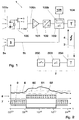
- Fig. 1 shows schematically a battery powered wireless Motion or presence detector 1.
- the detector 1 includes measuring means 100, 101, 102 and a control unit 103 for generating and evaluating a measurement signal 100b, with which the movement or presence 100a of an object is detectable.
- the detector 1 comprises an autonomous supply source 105 for at least temporary feeding at least a power consuming component 100, 101, 102, 103, 104 of the detector 1.
- the object to be detected may a person, an animal, a bicycle, a car o. ⁇ . act.
- the motion detector 1 is for example a Passive infrared detector 1 (PIR), but can also be an active Infrared detector based on infrared reflection, an active Ultrasonic detector based on ultrasonic reflection or Doppler effect, an acoustic sound detector, be an active microwave detector or the like.
- PIR Passive infrared detector 1
- a characteristic electric Measuring signal 100b from that with a field effect transistor, comprising drain D, collector and source S, the capacitive Ground GND is coupled, pre-amplified, in the signal amplifier 101 further amplified, in the A / D converter 102 in a digital Signal converted and finally in the microcontroller 103 is evaluated.
- the sensor part 1 can be operated with a battery 105 and the switching command from the sensor 1 to the actuator 2 through a wireless connection 3 are transmitted.
- the detector 1 a transmitter 104 and the actuator 2 a Receiver 204 based on radio waves, Microwaves, acoustic waves o. ⁇ . Can work.
- the actuator 2 includes its own microcontroller 203 and a switch 200, in particular a relay or a semiconductor switch 200 for controlling a light source, a blind, a fan, an air conditioner, a heater or other electrical appliances.
- a photosensitive element 5 is present detected by the ambient light 5a and a corresponding Ambient light signal 5b to the motion detector 1 and in particular its microcontroller 103 is forwarded. Suppress conventional battery powered motion detectors 1 then the trip command to the actuator 2 or the Relay 2, without going into a special power-saving mode switch.
- the ambient light signal 5a directly used the motion detector 1 as a function of the ambient light signal 5b between an operating mode 7 for detection readiness and an energy saving mode 8 for reducing the power consumption I the supply source 105 of the motion detector 1 switch.
- Switching takes place automatically and triggered by the Ambient light signal 5b.
- Set the switching means 103b that is, a control circuit 103b that is within or also can be arranged outside the control unit 103 and with their help by switching between operating mode 7 and power saving mode 8 extends the battery life is.
- the control circuit switches in dependence of Size of the ambient light signal and does not diminish in any Assure the measurement reliability of the motion detector 1.
- the control unit 103 comprises the switching means 103b and in particular the microcontroller 103.
- each measuring device 100 is preferably 100, 101, 102 switched off or switched to standby and the Control unit 103 is switched to standby insofar, that they are for a repeated measurement of ambient light 5a automatically and only as far as necessary can be activated.
- motion sensor 100, data acquisition part or signal processing unit 101, 102, evaluation electronics 103 for the personal identification and communication part 104 only to be active if in the environment a predefinable Brightness, whether dark or light, is present. If this is not the case, z. B. the microcontroller 103rd be switched into a low power mode 8 and only for the For example, measure the brightness once per second to be woken up. The rest of the electronics can be 100-104 stay switched off during this time.
- the switching means 103b comprise comparator means for comparing the ambient light signal 5b with a predefinable brightness threshold value 60; 61, 62 and calculating means for determining operating mode 7 or energy-saving mode 8 in function of the comparison.
- the energy saving mode 8 then, if by the motion detector 1, a light switch 200 are controlled should and the ambient light signal 5b above the brightness threshold 60; 61, 62 lies or if by the motion detector 1 is an ambient light 5a to be activated Installation 200, especially a sun blind or activated or daylight-dependent ventilation during the day, Air conditioning or office installation, to be controlled and the ambient light signal 5b below the brightness threshold 60; 61, 62 is located.
- Fig. 2 shows an embodiment of a motion detector 1 for activating a light switch 2. Shown is the brightness curve 6 as a function of Time of day t. When exceeding a threshold value of 60 am Tomorrow will switch to daytime energy-saving mode 8 and so that the motion detector 1 is deactivated. In the evening at Falling below the brightness threshold 60 is in the Night operating mode 7 switched and the motion detector 1 activated. To toggle during the transition phases to avoid a hysteresis is introduced in such a way that in the morning the threshold is 61, increased by one Trigger, and in the evening the threshold 62, spectaculard by one Trigger, serves as switching criterion. About the annual mean can such a battery powered motion detector 1 about half of the time in day mode 8 are operated.
- the battery life can be drastically reduced extend.
- Power consumption in Night operating mode 7 27 mA
- Power consumption in the daily energy-saving module 8 4 mA
- average power consumption 15.5 mA at half day / night operation The battery life extends by almost a factor of two, without consideration of additional self-discharge and Aging of the battery 105.
- the autonomous power source 105 may be any battery power, also a rechargeable battery or a rechargeable battery be.
- the battery 105 may also outside the Motion detector 1 may be arranged.
- the photosensitive element 5 is in the range the motion detector 1 and / or one of the motion detector.
- 1 controlled actuator 2 is arranged. It can be especially in Motion detector 1 or optionally in the actuator 2 itself be arranged.
- Detector 1 in wireless communication between Detector 1 and actuator 2 in addition to Hinkommunikation 3 to Command transmission to the actuator 2 also a return communication 4 to the detector 1 be present.
- the return communication 4 serves to order from the actuator 2 to the detector. 1 tell how good the send connection works and if necessary, the transmission power to an optimum level level and in particular lower.
- the subject of the invention is also a system for motion detection, comprising a motion detector 1 as before described and controlled by the motion detector 1 Actuator 2, as well as a device, an installation or a machine comprising such a motion detector. 1
- the invention relates to a scanning method for a motion detector 1, wherein at least a power consuming component 100, 101, 102, 103, 104 of the motion detector 1 at least temporarily from an autonomous supply source 105 is fed, wherein the Motion detector 1 a measurement signal 100b for detecting the Movement or presence 100a of an object and of a photosensitive element 5 an ambient light signal 5b is generated for the detection of ambient light 5a, wherein Further, in dependence of the ambient light signal 5b of Motion detector 1 between an operating mode 7 for DetektionsrText and an energy saving mode 8 for reduction the power consumption I of the supply source 105 is switched becomes.
- the ambient light signal 5b of Motion detector 1 between an operating mode 7 for DetektionsrText and an energy saving mode 8 for reduction the power consumption I of the supply source 105 is switched becomes.
- the motion detector can be independent of the measurement signal 100b in the operating mode 7 or energy-saving mode 8 are added.
- the energy-saving mode can be activated by default.
- the ambient light 5 a in the area of the motion detector 1 and / or an actuator controlled by the motion detector 1 2 measured; it can be daylight 5a and / or Artificial light 5a act.
- a control unit 103 of the motion detector 1 repeats a measurement of the ambient light 5a initiated and the resulting ambient light signal 5b with a brightness threshold 60; 61, 62 compared, the is in particular hysteresis and depending on the Comparison of the operating mode 7 or the energy-saving mode 8 activated.
- the control unit 103 so far switched to stand-by that they automatically and only as necessary for the repeated measurement of ambient light 5a is activated.
- the microcontroller 103 is running a clock, for example, every 1 s or 10 s the microcontroller 103 awakens and initiates measurement.
- energy-saving mode 8 So runs the control unit 103 only in one Minimum configuration required for periodic or repeated Monitoring the environment for brightness 5a and occasional Wake up the entire motion detector 1 serves.
- a light switch 200 is controlled and due to the Comparison of energy saving mode 8 activated when the brightness threshold 60; 61, 62 exceeded by the ambient light 5a becomes.
- the comparison is thus carried out so that the motion detector 1 in daylight largely inactive and is ready for detection in the dark.
- alternative can from the motion detector 1 in an ambient light 5a too activating installation 200, in particular a sun blind 200 or daytime activated ventilation, air conditioning or office installation, be controlled and due the comparison of the energy saving mode 8 are activated when the brightness threshold 60; 61, 62 from ambient light 5a is fallen short of.
- a sampling rate f 1 , f 2 , f 3 can be reduced with a decreasing residual life of the supply source 105 (FIGS. 3, 4).
- a sampling rate f, 13 can be left unchanged and intermittent sampling gaps 14 can be permitted (FIG. 5).
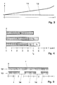
- FIG. 3 shows the power consumption I of a data acquisition system 101-103 or microcontroller 103 as a function the sampling rate or clock frequency f.
- the total power consumption I, 11 consists of a base load 10 and a part dependent on the sampling frequency f.
- the Base load 10 consists of the power consumption of the microcontroller 103 in sleep mode, the consumption of the amplifier 101 and the sensor 100 (if not switched off can be) as well as from leakage currents of other components together.
- the frequency-dependent part substantially decreases proportional and at high frequencies f disproportionately to the frequency f. So can the power consumption I one Data acquisition system 101-103, e.g. an analog / digital converter 102, approximately halved when the sampling rate f is reduced by a factor of two.
- the relevant sampling rates f of the infrared motion detector 1 for the evaluation and detection of a person are in a frequency range between approximately 0.1 Hz and 10 Hz.
- the system 1 can thus be operated for a longer time with a relatively slightly reduced detection reliability until the capacity of the battery 105 is completely used up.
- FIG. 5 shows an alternative or supplementary scanning method, where a scan is performed in burst mode becomes.
- a signal is given by equidistant or at least continuous scans 12 detected.
- the sample can also be in one Burst Mode 13 can be performed by capturing or Scanning gaps 14 are allowed.
- the sampling rate f remains unchanged, but is temporarily suspended or interrupted.
- the burst mode 13 can be basically independent operated by a remaining life of the battery 105 become.
- Power consumption I can be reduced all the more, the longer the coverage gaps 14 are selected in burst mode 13 become.
- the loss is that traceability of the motion signal 100b becomes worse and mainly prolonged the reaction or response time until a movement 100a can be detected.
- One good compromise exists when a ratio dead time 14 or sleep mode 14 at waking time is chosen so that persons not unguarded or unnoticed one to be controlled Area can happen. This is a dead time 14th or acquisition gap 14 from 100 ms to a few 100 ms in general tolerable.
- the burst mode 13 can also with increasing battery life ever longer sampling gaps Allow 14 so that the battery life at ever lower availability over long periods of time remains intermittently available.
- the scanning methods according to FIGS. 4 and 5 are freely combinable with the method according to the invention and in particular with each other. Overall, a minimum sampling rate over a minimum period should be ensured in any case for detecting moving persons, cyclists, cars o. ⁇ .
- the reduction of the sampling frequency f 1 , f 2 , f 3 and the admission of sampling gaps 14 will also be determined depending on a spatial area to be monitored, a field of view and in dependence of several motion detectors 1.
Landscapes
- Physics & Mathematics (AREA)
- General Physics & Mathematics (AREA)
- Engineering & Computer Science (AREA)
- Computer Security & Cryptography (AREA)
- Photometry And Measurement Of Optical Pulse Characteristics (AREA)
- Geophysics And Detection Of Objects (AREA)
- Measurement Of Optical Distance (AREA)
- Length Measuring Devices By Optical Means (AREA)
- Charge And Discharge Circuits For Batteries Or The Like (AREA)
Abstract
Description
- Fig. 1
- ein Blockdiagramm eines batteriebetriebenen Bewegungsmelders mit Funkanbindung an einen Aktuator;
- Fig. 2
- einen ersten Stromsparbetrieb des Bewegungsmelders mit einem alternierenden Tag- und Nachtbetriebsmode;
- Fig. 3
- einen Stromverbrauch des Bewegungsmelders in Funktion der Abtastrate seines Bewegungssensors;
- Fig. 4
- schematisch einen zweiten Stromsparbetrieb des Bewegungsmelders mit reduzierter Abtastrate; und
- Fig. 5
- schematisch einen dritten Stromsparbetrieb des Bewegungsmelders mit Zulassung von Abtastlücken.
- 1
- Autonomer Bewegungsmelder
- 100
- Bewegungssensor, pyroelektrischer Detektor, Passiv-Infrarotdetektor (PIR)
- 100a
- Bewegungssignal, Anwesenheitssignal, Wärmestrahlung
- 100b
- Messsignal
- 101
- Signalverstärker
- 102
- A/D-Wandler
- 103
- Kontrolleinheit, Mikrokontroller, µC, Mikroprozessor
- 103b
- Umschaltmittel
- 104
- Kommunikationsteil, Sender, Transceiver
- 105
- autonome Speisequelle, Batterie
- 2
- Aktuator
- 200
- Lichtschalter, Jalousiesteuerung
- 203
- Kontrolleinheit, Mikrokontroller, µC, Mikroprozessor
- 204
- Kommunikationsteil, Empfänger, Transceiver
- 3
- Hinkommunikation, Befehlsrichtung
- 4
- Rückkommunikation
- 5
- lichtempfindliches Element, Photowiderstand, Phototransistor
- 5a
- Umgebungslicht, Tageslicht, Kunstlicht
- 5b
- Umgebungslichtsignal
- 6
- Helligkeitsverlauf
- 60
- Schwellwert für Helligkeit, Trigger
- 61
- Helligkeitsschwellwert plus Hysterese
- 62
- Helligkeitsschwellwert minus Hysterese
- 7
- Betriebsmode, Nacht-Betriebsmodus
- 8
- Energiesparmode, Tag-Betriebsmodus
- 9
- Stromverbrauch, Energieverbrauch
- 10
- Stromverbrauchsgrundlast
- 11
- Gesamtstromverbrauch
- 12
- Kontinuierliche Abtastung
- 13
- intermittierende (Burst-Mode) Abtastung
- 14
- Abtastlücken
- A, A'
- pyroelektrische Kristalle
- A/D
- analog/digital
- D
- Drain
- S
- Source
- GND
- Ground, Erdung
- f, f1, f2, f3
- Abtastrate, Taktfrequenz
- I
- Stromverbrauch
- t
- Tageszeit, Uhrzeit
- T
- Batterielebensdauer (in Jahren)
- TE
- prognostizierte Batterielebensdauer
Claims (14)
- Abtastverfahren für einen Bewegungsmelder (1), wobei mindestens eine stromverbrauchende Komponente (100, 101, 102, 103, 104) des Bewegungsmelders (1) mindestens zeitweise von einer autonomen Speisequelle (105) gespeist wird, wobei vom Bewegungsmelder (1) ein Messsignal (100b) zur Detektion der Bewegung oder Anwesenheit (100a) eines Objekts und von einem lichtempfindlichen Element (5) ein Umgebungslichtsignal (5b) zur Detektion von Umgebungslicht (5a) erzeugt wird, dadurch gekennzeichnet, dass in Abhängigkeit des Umgebungslichtsignals (5b) der Bewegungsmelder (1) zwischen einem Betriebsmode (7) für Detektionsbereitschaft und einem Energiesparmode (8) zur Reduktion des Stromverbrauchs (I) der Speisequelle (105) umgeschaltet wird.
- Abtastverfahren nach Anspruch 1, dadurch gekennzeichnet, dassa) der Bewegungsmelder (1) unabhängig vom Messsignal (100b) in den Betriebsmode (7) oder Energiesparmode (8) versetzt wird und/oderb) der Energiesparmode defaultmässig aktiviert wird und/oderc) im Energiesparmode (8) mindestens eine der mindestens einen stromverbrauchenden Komponente (100, 101, 102, 103, 104) des Bewegungsmelders (1), insbesondere jede der stromverbrauchenden Komponenten (100, 101, 102, 103, 104), ausgeschaltet oder auf Stand-by geschaltet wird.
- Abtastverfahren nach einem der vorangehenden Ansprüche, dadurch gekennzeichnet, dassa) das Umgebungslicht (5a) im Bereich des Bewegungsmelders (1) und/oder eines vom Bewegungsmelder (1) gesteuerten Aktuators (2) gemessen wird und/oderb) das Umgebungslicht (5a) Tageslicht und/oder Kunstlicht ist.
- Abtastverfahren nach einem der vorangehenden Ansprüche, dadurch gekennzeichnet, dassa) von einer Kontrolleinheit (103) des Bewegungsmelders (1) wiederholt eine Messung des Umgebungslichts (5a) initiiert und das resultierende Umgebungslichtsignal (5b) mit einem Helligkeitsschwellwert (60; 61, 62) verglichen wird, der insbesondere hysteresebehaftet ist,b) in Abhängigkeit des Vergleichs der Betriebsmode (7) oder der Energiesparmode (8) aktiviert wird undc) im Energiesparmode (8) die Kontrolleinheit (103) insoweit auf Stand-by geschaltet wird, dass sie selbsttätig und nur soweit nötig für die wiederholte Messung des Umgebungslichts (5a) aktiviert werden kann.
- Abtastverfahren nach Anspruch 4, dadurch gekennzeichnet, dassa) vom Bewegungsmelder (1) ein Lichtschalter (200) gesteuert wird und aufgrund des Vergleichs der Energiesparmode (8) aktiviert wird, wenn der Helligkeitsschwellwert (60; 61, 62) vom Umgebungslicht (5a) überschritten wird oderb) vom Bewegungsmelder (1) eine bei Umgebungslicht (5a) zu aktivierende Installation (200), insbesondere eine Sonnenjalousie (200) oder tagsüber aktivierbare Ventilation, Klimaanlage oder Büroinstallation, gesteuert wird und aufgrund des Vergleichs der Energiesparmode (8) aktiviert wird, wenn der Helligkeitsschwellwert (60; 61, 62) vom Umgebungslicht (5a) unterschritten wird.
- Abtastverfahren nach einem der vorangehenden Ansprüche, dadurch gekennzeichnet, dass zur Reduktion des Stromverbrauchs (I) der Speisequelle (105)a) eine Abtastrate (f1, f2, f3) mit einer abnehmenden Restlebensdauer der Speisequelle (105) reduziert wird und/oderb) eine Abtastrate (f, 13) unverändert belassen wird und intermittierende Abtastlücken (14) zugelassen werden.
- Bewegungsmelder (1), umfassend Messmittel (100, 101, 102) und eine Kontrolleinheit (103) zur Erzeugung und Auswertung eines Messsignals (100b) zur Detektion der Bewegung oder Anwesenheit (100a) eines Objekts sowie eine autonome Speisequelle (105) zur mindestens zeitweisen Speisung mindestens einer stromverbrauchenden Komponente (100, 101, 102, 103, 104) des Bewegungsmelders (1), wobei ferner ein lichtempfindliches Element (5) zur Erzeugung eines Umgebungslichtsignals (5a) in Abhängigkeit eines Umgebungslichts (5a) vorhanden ist, dadurch gekennzeichnet, dassa) der Bewegungsmelder (1) einen Betriebsmode (7) für Detektionsbereitschaft und einen Energiesparmode (8) zur Reduktion des Stromverbrauchs (I) der Speisequelle (105) aufweist undb) Umschaltmittel (103b) zum selbsttätigen Umschalten des Bewegungsmelders (1) zwischen dem Betriebsmode (7) und dem Energiesparmode (8) in Abhängigkeit einer Grösse des Umgebungslichtsignals (5b) vorhanden sind.
- Bewegungsmelder (1) nach Anspruch 7, dadurch gekennzeichnet, dassa) im Energiesparmode (8) jedes Messmittel (100, 101, 102) ausgeschaltet oder auf Stand-by geschaltet ist und die Kontrolleinheit (103) insoweit auf Stand-by geschaltet ist, dass sie für eine wiederholte Messung des Umgebungslichts (5a) selbsttätig und nur soweit nötig aktivierbar ist und/oderb) die Kontrolleinheit (103) die Umschaltmittel (103b) umfasst und insbesondere ein Mikrokontroller (103) ist.
- Bewegungsmelder (1) nach einem der Ansprüche 7-8, dadurch gekennzeichnet, dassa) die Umschaltmittel (103b) Komparatormittel zum Vergleich des Umgebungslichtsignals (5b) mit einem vorgebbaren Helligkeitsschwellwert (60; 61, 62) umfassen undb) die Umschaltmittel (103b) Rechenmittel zur Bestimmung des Betriebsmodes (7) oder Energiesparmodes (8) in Funktion des Vergleichs umfassen.
- Bewegungsmelder (1) nach Anspruch 9, dadurch gekennzeichnet, dass die Umschaltmittel (103b) den Energiesparmode (8) aktivieren, wenna) durch den Bewegungsmelder (1) ein Lichtschalter (200) gesteuert werden soll und das Umgebungslichtsignal (5b) über dem Helligkeitsschwellwert (60; 61, 62) liegt oderb) durch den Bewegungsmelder (1) eine bei Umgebungslicht (5a) zu aktivierende Installation (200), insbesondere eine Sonnenjalousie (200) oder tagsüber aktivierbare Ventilation, Klimaanlage oder Büroinstallation, gesteuert werden soll und das Umgebungslichtsignal (5b) unter dem Helligkeitsschwellwert (60; 61, 62) liegt.
- Bewegungsmelder (1) nach einem der Ansprüche 7-10, dadurch gekennzeichnet, dassa) die Messmittel (100, 101, 102) einen Bewegungssensor (100), eine Signalverarbeitungseinheit (101, 102), insbesondere einen Signalverstärker (101) und einen A/D-Wandler (102), und Kommunikationsmittel (104) zur Ansteuerung eines Aktuators (2) umfassen undb) insbesondere dass der Bewegungssensor (100) zur Detektion von Mensch, Tier und/oder Fahrzeug ausgelegt ist und vorzugsweise ein Passiv-Infrarotdetektor (1) ist.
- Bewegungsmelder (1) nach einem der Ansprüche 7-11, dadurch gekennzeichnet, dassa) die Speisequelle (105) eine Batteriespeisung (105) des Bewegungsmelders (1), insbesondere eine wiederaufladbare Batterie, ist und/oderb) das lichtempfindliche Element (5) im Bereich des Bewegungsmelders (1) und/oder eines vom Bewegungsmelder (1) gesteuerten Aktuators (2) angeordnet ist und/oderc) Mittel zur drahtlosen Rückkommunikation (4) vom Aktuator (2) zum Bewegungsmelder (1) und zur Anpassung einer Sendeleistung des Bewegungsmelders (1) an ein erforderliches Leistungsniveau vorhanden sind.
- System zur Bewegungsmeldung, umfassend einen Bewegungsmelder (1) gemäss einem der Ansprüche 7-12 und einen durch den Bewegungsmelder (1) gesteuerten Aktuator (2).
- Gerät, Installation oder Maschine, umfassend einen Bewegungsmelder (1) nach einem der Ansprüche 7-12.
Applications Claiming Priority (2)
| Application Number | Priority Date | Filing Date | Title |
|---|---|---|---|
| DE10356071A DE10356071A1 (de) | 2003-12-01 | 2003-12-01 | Verfahren und Vorrichtung zur Reduktion des Stromverbrauchs in batteriebetriebenen Bewegungsmeldern |
| DE10356071 | 2003-12-01 |
Publications (2)
| Publication Number | Publication Date |
|---|---|
| EP1538579A1 true EP1538579A1 (de) | 2005-06-08 |
| EP1538579B1 EP1538579B1 (de) | 2006-09-27 |
Family
ID=34442381
Family Applications (1)
| Application Number | Title | Priority Date | Filing Date |
|---|---|---|---|
| EP04405734A Expired - Lifetime EP1538579B1 (de) | 2003-12-01 | 2004-11-25 | Verfahren und Vorrichtung zur Reduktion des Stromverbrauchs in batteriebetriebenen Bewegungsmeldern |
Country Status (3)
| Country | Link |
|---|---|
| EP (1) | EP1538579B1 (de) |
| AT (1) | ATE341058T1 (de) |
| DE (2) | DE10356071A1 (de) |
Cited By (6)
| Publication number | Priority date | Publication date | Assignee | Title |
|---|---|---|---|---|
| WO2008020223A1 (en) * | 2006-08-16 | 2008-02-21 | Circuitree Limited | Context monitoring for remote sensor platforms |
| WO2010140094A1 (en) * | 2009-06-04 | 2010-12-09 | Koninklijke Philips Electronics N.V. | Wake-up of light sensor in a lighting system |
| WO2010085543A3 (en) * | 2009-01-26 | 2011-01-27 | Lutron Electronics Company, Inc. | Multi-modal load control system having occupancy sensing |
| EP2194553A3 (de) * | 2008-11-12 | 2017-04-19 | Waldemar Stach | Stromsparende Sensorschaltung |
| WO2017171962A3 (en) * | 2016-01-11 | 2017-12-07 | Carrier Corporation | Infrared presence detector system |
| CN114166356A (zh) * | 2021-12-06 | 2022-03-11 | 普联技术有限公司 | Pir阈值调整方法、pir阈值调整系统以及监测装置 |
Families Citing this family (4)
| Publication number | Priority date | Publication date | Assignee | Title |
|---|---|---|---|---|
| DE102005042568B3 (de) * | 2005-09-08 | 2007-01-04 | Abb Research Ltd. | Funk-Bewegungsmelder |
| DE102008004420A1 (de) * | 2008-01-14 | 2009-07-16 | Elmos Semiconductor Ag | Beleuchtungssystem für Innenräume sowie Verfahren zu dessen Steuerung |
| DE102008004419A1 (de) * | 2008-01-14 | 2009-07-16 | Elmos Semiconductor Ag | Beleuchtungsvorrichtung als Außenbeleuchtung und Verfahren zu deren Steuerung |
| DE102016124796A1 (de) * | 2016-12-19 | 2018-06-21 | Endress+Hauser Conducta Gmbh+Co. Kg | Sensorkopfmodul zur kontinuierlichen automatisierten Datenerfassung |
Citations (2)
| Publication number | Priority date | Publication date | Assignee | Title |
|---|---|---|---|---|
| US5128654A (en) * | 1990-02-23 | 1992-07-07 | Lightolier Incorporated | Preset light controller including infrared sensor operable in multiple modes |
| US5892446A (en) * | 1997-03-10 | 1999-04-06 | Reich; Lee A. | Wild animal deterrent device |
Family Cites Families (4)
| Publication number | Priority date | Publication date | Assignee | Title |
|---|---|---|---|---|
| US4890093A (en) * | 1988-10-27 | 1989-12-26 | Schlage Lock Company | Solar powered proximity triggered light |
| US5973594A (en) * | 1995-03-29 | 1999-10-26 | Hubbell Incorporated | Multiple optical designs for a multifunction sensor |
| DE19814591A1 (de) * | 1998-04-01 | 1999-10-07 | Merten Gmbh & Co Kg Geb | Verfahren und Präsenzmelder zum Steuern einer Beleuchtungseinrichtung |
| DE19913841A1 (de) * | 1999-03-27 | 2000-09-28 | Hansjoerg Klein | System zur Überwachung von schützenswerten Objekten in Räumen von Immobilien oder von mobilem Eigentum |
-
2003
- 2003-12-01 DE DE10356071A patent/DE10356071A1/de not_active Withdrawn
-
2004
- 2004-11-25 DE DE502004001582T patent/DE502004001582D1/de not_active Expired - Lifetime
- 2004-11-25 EP EP04405734A patent/EP1538579B1/de not_active Expired - Lifetime
- 2004-11-25 AT AT04405734T patent/ATE341058T1/de not_active IP Right Cessation
Patent Citations (2)
| Publication number | Priority date | Publication date | Assignee | Title |
|---|---|---|---|---|
| US5128654A (en) * | 1990-02-23 | 1992-07-07 | Lightolier Incorporated | Preset light controller including infrared sensor operable in multiple modes |
| US5892446A (en) * | 1997-03-10 | 1999-04-06 | Reich; Lee A. | Wild animal deterrent device |
Cited By (15)
| Publication number | Priority date | Publication date | Assignee | Title |
|---|---|---|---|---|
| WO2008020223A1 (en) * | 2006-08-16 | 2008-02-21 | Circuitree Limited | Context monitoring for remote sensor platforms |
| EP2194553A3 (de) * | 2008-11-12 | 2017-04-19 | Waldemar Stach | Stromsparende Sensorschaltung |
| US8665090B2 (en) | 2009-01-26 | 2014-03-04 | Lutron Electronics Co., Inc. | Multi-modal load control system having occupancy sensing |
| WO2010085543A3 (en) * | 2009-01-26 | 2011-01-27 | Lutron Electronics Company, Inc. | Multi-modal load control system having occupancy sensing |
| US8842008B2 (en) | 2009-01-26 | 2014-09-23 | Lutron Electronics Co., Inc. | Multi-modal load control system having occupancy sensing |
| CN102461335A (zh) * | 2009-06-04 | 2012-05-16 | 皇家飞利浦电子股份有限公司 | 照明系统中光传感器的唤醒 |
| US8638036B2 (en) | 2009-06-04 | 2014-01-28 | Koninklijke Philips N.V. | Wake-up of light sensor in a lighting system |
| CN102461335B (zh) * | 2009-06-04 | 2016-03-02 | 皇家飞利浦电子股份有限公司 | 照明系统中光传感器的唤醒装置及方法 |
| WO2010140094A1 (en) * | 2009-06-04 | 2010-12-09 | Koninklijke Philips Electronics N.V. | Wake-up of light sensor in a lighting system |
| WO2017171962A3 (en) * | 2016-01-11 | 2017-12-07 | Carrier Corporation | Infrared presence detector system |
| US11525735B2 (en) | 2016-01-11 | 2022-12-13 | Carrier Corporation | Infrared presence detector system |
| EP4187218A1 (de) * | 2016-01-11 | 2023-05-31 | Carrier Corporation | Detektorsystem für infrarotanwesenheit |
| US12061119B2 (en) | 2016-01-11 | 2024-08-13 | Carrier Corporation | Infrared presence detector system |
| CN114166356A (zh) * | 2021-12-06 | 2022-03-11 | 普联技术有限公司 | Pir阈值调整方法、pir阈值调整系统以及监测装置 |
| CN114166356B (zh) * | 2021-12-06 | 2024-02-13 | 普联技术有限公司 | Pir阈值调整方法、pir阈值调整系统以及监测装置 |
Also Published As
| Publication number | Publication date |
|---|---|
| DE10356071A1 (de) | 2005-06-23 |
| DE502004001582D1 (de) | 2006-11-09 |
| EP1538579B1 (de) | 2006-09-27 |
| ATE341058T1 (de) | 2006-10-15 |
Similar Documents
| Publication | Publication Date | Title |
|---|---|---|
| WO2005055017A2 (de) | Verfahren und vorrichtung zur reduktion des stromverbrauchs in batteriebetriebenen geräten | |
| AU2022200102B2 (en) | Machine learning motion sensing with auxiliary sensors | |
| DE69832259T2 (de) | Anwesenheitssensor und sein betriebsverfahren | |
| DE60128684T2 (de) | Prozessorgest tzter drahtloser detektor | |
| DE10150128A1 (de) | Drahtloses Sensorsystem | |
| US5127575A (en) | Supervisory control unit for electrical equipment | |
| DE212014000146U1 (de) | Systeme für multikriterielle Alarme | |
| DE69615006T2 (de) | Verfahren zur steuerung eines anwesenheitssensors | |
| KR100979185B1 (ko) | 공조 설비 통제 제어 시스템 | |
| EP1538579B1 (de) | Verfahren und Vorrichtung zur Reduktion des Stromverbrauchs in batteriebetriebenen Bewegungsmeldern | |
| DE212014000144U1 (de) | Gefahrenmeldeanlagen mit gegabelten Prozessoren | |
| EP2954647B1 (de) | Verfahren und steuerungsvorrichtung zum ein- und ausschalten von einem nachtmodus einer heizungs- und/oder klimaanlage | |
| EP0724044A1 (de) | Steuerung für eine Sanitärarmatur | |
| CN107631802B (zh) | 被动式红外探测器的控制方法和装置 | |
| DE19704597C2 (de) | Monitor-Stromversorgungs-Stellschaltung für Computersysteme | |
| CN108010260A (zh) | 一种输电线路智能防鸟害监测预警系统及其工作方法 | |
| DE10393173T5 (de) | Bestätigungseinheit für bewegbare Barrieren mit Energiemanagementsteuerung und entsprechendem Verfahren | |
| Bai et al. | Design and implementation of a home embedded surveillance system with ultra-low alert power | |
| DE3719087C2 (de) | Alarmabschalteinrichtung für eine Wecker- oder Terminuhr | |
| CN105046883A (zh) | 监护告警系统及其方法 | |
| DE3706229C2 (de) | ||
| CN106440213A (zh) | 空调及其控制方法和控制系统 | |
| EP3318948B1 (de) | Heizkörperthermostat | |
| CN106658893A (zh) | 一种照明控制方法、装置以及探测设备、照明系统 | |
| EP2453426B1 (de) | Überwachungssensor mit Selbsttest |
Legal Events
| Date | Code | Title | Description |
|---|---|---|---|
| PUAI | Public reference made under article 153(3) epc to a published international application that has entered the european phase |
Free format text: ORIGINAL CODE: 0009012 |
|
| AK | Designated contracting states |
Kind code of ref document: A1 Designated state(s): AT BE BG CH CY CZ DE DK EE ES FI FR GB GR HU IE IS IT LI LU MC NL PL PT RO SE SI SK TR |
|
| AX | Request for extension of the european patent |
Extension state: AL HR LT LV MK YU |
|
| 17P | Request for examination filed |
Effective date: 20051010 |
|
| AKX | Designation fees paid |
Designated state(s): AT BE BG CH CY CZ DE DK EE ES FI FR GB GR HU IE IS IT LI LU MC NL PL PT RO SE SI SK TR |
|
| GRAP | Despatch of communication of intention to grant a patent |
Free format text: ORIGINAL CODE: EPIDOSNIGR1 |
|
| GRAS | Grant fee paid |
Free format text: ORIGINAL CODE: EPIDOSNIGR3 |
|
| GRAA | (expected) grant |
Free format text: ORIGINAL CODE: 0009210 |
|
| AK | Designated contracting states |
Kind code of ref document: B1 Designated state(s): AT BE BG CH CY CZ DE DK EE ES FI FR GB GR HU IE IS IT LI LU MC NL PL PT RO SE SI SK TR |
|
| PG25 | Lapsed in a contracting state [announced via postgrant information from national office to epo] |
Ref country code: IT Free format text: LAPSE BECAUSE OF FAILURE TO SUBMIT A TRANSLATION OF THE DESCRIPTION OR TO PAY THE FEE WITHIN THE PRESCRIBED TIME-LIMIT;WARNING: LAPSES OF ITALIAN PATENTS WITH EFFECTIVE DATE BEFORE 2007 MAY HAVE OCCURRED AT ANY TIME BEFORE 2007. THE CORRECT EFFECTIVE DATE MAY BE DIFFERENT FROM THE ONE RECORDED. Effective date: 20060927 Ref country code: SK Free format text: LAPSE BECAUSE OF FAILURE TO SUBMIT A TRANSLATION OF THE DESCRIPTION OR TO PAY THE FEE WITHIN THE PRESCRIBED TIME-LIMIT Effective date: 20060927 Ref country code: SI Free format text: LAPSE BECAUSE OF FAILURE TO SUBMIT A TRANSLATION OF THE DESCRIPTION OR TO PAY THE FEE WITHIN THE PRESCRIBED TIME-LIMIT Effective date: 20060927 Ref country code: PL Free format text: LAPSE BECAUSE OF FAILURE TO SUBMIT A TRANSLATION OF THE DESCRIPTION OR TO PAY THE FEE WITHIN THE PRESCRIBED TIME-LIMIT Effective date: 20060927 Ref country code: RO Free format text: LAPSE BECAUSE OF FAILURE TO SUBMIT A TRANSLATION OF THE DESCRIPTION OR TO PAY THE FEE WITHIN THE PRESCRIBED TIME-LIMIT Effective date: 20060927 Ref country code: NL Free format text: LAPSE BECAUSE OF FAILURE TO SUBMIT A TRANSLATION OF THE DESCRIPTION OR TO PAY THE FEE WITHIN THE PRESCRIBED TIME-LIMIT Effective date: 20060927 Ref country code: FI Free format text: LAPSE BECAUSE OF FAILURE TO SUBMIT A TRANSLATION OF THE DESCRIPTION OR TO PAY THE FEE WITHIN THE PRESCRIBED TIME-LIMIT Effective date: 20060927 Ref country code: IE Free format text: LAPSE BECAUSE OF FAILURE TO SUBMIT A TRANSLATION OF THE DESCRIPTION OR TO PAY THE FEE WITHIN THE PRESCRIBED TIME-LIMIT Effective date: 20060927 Ref country code: CZ Free format text: LAPSE BECAUSE OF FAILURE TO SUBMIT A TRANSLATION OF THE DESCRIPTION OR TO PAY THE FEE WITHIN THE PRESCRIBED TIME-LIMIT Effective date: 20060927 |
|
| REG | Reference to a national code |
Ref country code: GB Ref legal event code: FG4D Free format text: NOT ENGLISH |
|
| REG | Reference to a national code |
Ref country code: CH Ref legal event code: EP |
|
| REG | Reference to a national code |
Ref country code: IE Ref legal event code: FG4D Free format text: LANGUAGE OF EP DOCUMENT: GERMAN |
|
| REF | Corresponds to: |
Ref document number: 502004001582 Country of ref document: DE Date of ref document: 20061109 Kind code of ref document: P |
|
| PG25 | Lapsed in a contracting state [announced via postgrant information from national office to epo] |
Ref country code: MC Free format text: LAPSE BECAUSE OF NON-PAYMENT OF DUE FEES Effective date: 20061130 Ref country code: BE Free format text: LAPSE BECAUSE OF NON-PAYMENT OF DUE FEES Effective date: 20061130 |
|
| PG25 | Lapsed in a contracting state [announced via postgrant information from national office to epo] |
Ref country code: SE Free format text: LAPSE BECAUSE OF FAILURE TO SUBMIT A TRANSLATION OF THE DESCRIPTION OR TO PAY THE FEE WITHIN THE PRESCRIBED TIME-LIMIT Effective date: 20061227 Ref country code: BG Free format text: LAPSE BECAUSE OF FAILURE TO SUBMIT A TRANSLATION OF THE DESCRIPTION OR TO PAY THE FEE WITHIN THE PRESCRIBED TIME-LIMIT Effective date: 20061227 Ref country code: DK Free format text: LAPSE BECAUSE OF FAILURE TO SUBMIT A TRANSLATION OF THE DESCRIPTION OR TO PAY THE FEE WITHIN THE PRESCRIBED TIME-LIMIT Effective date: 20061227 |
|
| PG25 | Lapsed in a contracting state [announced via postgrant information from national office to epo] |
Ref country code: ES Free format text: LAPSE BECAUSE OF FAILURE TO SUBMIT A TRANSLATION OF THE DESCRIPTION OR TO PAY THE FEE WITHIN THE PRESCRIBED TIME-LIMIT Effective date: 20070107 |
|
| PG25 | Lapsed in a contracting state [announced via postgrant information from national office to epo] |
Ref country code: IS Free format text: LAPSE BECAUSE OF FAILURE TO SUBMIT A TRANSLATION OF THE DESCRIPTION OR TO PAY THE FEE WITHIN THE PRESCRIBED TIME-LIMIT Effective date: 20070127 |
|
| NLV1 | Nl: lapsed or annulled due to failure to fulfill the requirements of art. 29p and 29m of the patents act | ||
| PG25 | Lapsed in a contracting state [announced via postgrant information from national office to epo] |
Ref country code: PT Free format text: LAPSE BECAUSE OF FAILURE TO SUBMIT A TRANSLATION OF THE DESCRIPTION OR TO PAY THE FEE WITHIN THE PRESCRIBED TIME-LIMIT Effective date: 20070313 |
|
| REG | Reference to a national code |
Ref country code: IE Ref legal event code: FD4D |
|
| GBV | Gb: ep patent (uk) treated as always having been void in accordance with gb section 77(7)/1977 [no translation filed] |
Effective date: 20060927 |
|
| EN | Fr: translation not filed | ||
| PLBE | No opposition filed within time limit |
Free format text: ORIGINAL CODE: 0009261 |
|
| STAA | Information on the status of an ep patent application or granted ep patent |
Free format text: STATUS: NO OPPOSITION FILED WITHIN TIME LIMIT |
|
| 26N | No opposition filed |
Effective date: 20070628 |
|
| PG25 | Lapsed in a contracting state [announced via postgrant information from national office to epo] |
Ref country code: GB Free format text: LAPSE BECAUSE OF FAILURE TO SUBMIT A TRANSLATION OF THE DESCRIPTION OR TO PAY THE FEE WITHIN THE PRESCRIBED TIME-LIMIT Effective date: 20060927 |
|
| BERE | Be: lapsed |
Owner name: ABB RESEARCH LTD. Effective date: 20061130 |
|
| PG25 | Lapsed in a contracting state [announced via postgrant information from national office to epo] |
Ref country code: AT Free format text: LAPSE BECAUSE OF NON-PAYMENT OF DUE FEES Effective date: 20061125 |
|
| PG25 | Lapsed in a contracting state [announced via postgrant information from national office to epo] |
Ref country code: GR Free format text: LAPSE BECAUSE OF FAILURE TO SUBMIT A TRANSLATION OF THE DESCRIPTION OR TO PAY THE FEE WITHIN THE PRESCRIBED TIME-LIMIT Effective date: 20061228 Ref country code: FR Free format text: LAPSE BECAUSE OF FAILURE TO SUBMIT A TRANSLATION OF THE DESCRIPTION OR TO PAY THE FEE WITHIN THE PRESCRIBED TIME-LIMIT Effective date: 20070525 |
|
| PG25 | Lapsed in a contracting state [announced via postgrant information from national office to epo] |
Ref country code: EE Free format text: LAPSE BECAUSE OF FAILURE TO SUBMIT A TRANSLATION OF THE DESCRIPTION OR TO PAY THE FEE WITHIN THE PRESCRIBED TIME-LIMIT Effective date: 20060927 |
|
| PG25 | Lapsed in a contracting state [announced via postgrant information from national office to epo] |
Ref country code: HU Free format text: LAPSE BECAUSE OF FAILURE TO SUBMIT A TRANSLATION OF THE DESCRIPTION OR TO PAY THE FEE WITHIN THE PRESCRIBED TIME-LIMIT Effective date: 20070328 Ref country code: LU Free format text: LAPSE BECAUSE OF NON-PAYMENT OF DUE FEES Effective date: 20061125 Ref country code: TR Free format text: LAPSE BECAUSE OF FAILURE TO SUBMIT A TRANSLATION OF THE DESCRIPTION OR TO PAY THE FEE WITHIN THE PRESCRIBED TIME-LIMIT Effective date: 20060927 |
|
| PG25 | Lapsed in a contracting state [announced via postgrant information from national office to epo] |
Ref country code: CY Free format text: LAPSE BECAUSE OF FAILURE TO SUBMIT A TRANSLATION OF THE DESCRIPTION OR TO PAY THE FEE WITHIN THE PRESCRIBED TIME-LIMIT Effective date: 20060927 Ref country code: FR Free format text: LAPSE BECAUSE OF FAILURE TO SUBMIT A TRANSLATION OF THE DESCRIPTION OR TO PAY THE FEE WITHIN THE PRESCRIBED TIME-LIMIT Effective date: 20060927 |
|
| REG | Reference to a national code |
Ref country code: CH Ref legal event code: PL |
|
| PG25 | Lapsed in a contracting state [announced via postgrant information from national office to epo] |
Ref country code: CH Free format text: LAPSE BECAUSE OF NON-PAYMENT OF DUE FEES Effective date: 20081130 Ref country code: LI Free format text: LAPSE BECAUSE OF NON-PAYMENT OF DUE FEES Effective date: 20081130 |
|
| PGFP | Annual fee paid to national office [announced via postgrant information from national office to epo] |
Ref country code: DE Payment date: 20091120 Year of fee payment: 6 |
|
| REG | Reference to a national code |
Ref country code: DE Ref legal event code: R119 Ref document number: 502004001582 Country of ref document: DE Effective date: 20110601 Ref country code: DE Ref legal event code: R119 Ref document number: 502004001582 Country of ref document: DE Effective date: 20110531 |
|
| PG25 | Lapsed in a contracting state [announced via postgrant information from national office to epo] |
Ref country code: DE Free format text: LAPSE BECAUSE OF NON-PAYMENT OF DUE FEES Effective date: 20110531 |