EP1538447B1 - Reagenzbehälter - Google Patents
Reagenzbehälter Download PDFInfo
- Publication number
- EP1538447B1 EP1538447B1 EP04028351A EP04028351A EP1538447B1 EP 1538447 B1 EP1538447 B1 EP 1538447B1 EP 04028351 A EP04028351 A EP 04028351A EP 04028351 A EP04028351 A EP 04028351A EP 1538447 B1 EP1538447 B1 EP 1538447B1
- Authority
- EP
- European Patent Office
- Prior art keywords
- reagent
- reagent container
- container
- containers
- reagent containers
- Prior art date
- Legal status (The legal status is an assumption and is not a legal conclusion. Google has not performed a legal analysis and makes no representation as to the accuracy of the status listed.)
- Expired - Lifetime
Links
Images


Classifications
-
- G—PHYSICS
- G01—MEASURING; TESTING
- G01N—INVESTIGATING OR ANALYSING MATERIALS BY DETERMINING THEIR CHEMICAL OR PHYSICAL PROPERTIES
- G01N35/00—Automatic analysis not limited to methods or materials provided for in any single one of groups G01N1/00 - G01N33/00; Handling materials therefor
- G01N35/10—Devices for transferring samples or any liquids to, in, or from, the analysis apparatus, e.g. suction devices, injection devices
- G01N35/1002—Reagent dispensers
-
- B—PERFORMING OPERATIONS; TRANSPORTING
- B01—PHYSICAL OR CHEMICAL PROCESSES OR APPARATUS IN GENERAL
- B01L—CHEMICAL OR PHYSICAL LABORATORY APPARATUS FOR GENERAL USE
- B01L3/00—Containers or dishes for laboratory use, e.g. laboratory glassware; Droppers
- B01L3/08—Flasks
-
- B—PERFORMING OPERATIONS; TRANSPORTING
- B65—CONVEYING; PACKING; STORING; HANDLING THIN OR FILAMENTARY MATERIAL
- B65D—CONTAINERS FOR STORAGE OR TRANSPORT OF ARTICLES OR MATERIALS, e.g. BAGS, BARRELS, BOTTLES, BOXES, CANS, CARTONS, CRATES, DRUMS, JARS, TANKS, HOPPERS, FORWARDING CONTAINERS; ACCESSORIES, CLOSURES, OR FITTINGS THEREFOR; PACKAGING ELEMENTS; PACKAGES
- B65D21/00—Nestable, stackable or joinable containers; Containers of variable capacity
- B65D21/02—Containers specially shaped, or provided with fittings or attachments, to facilitate nesting, stacking, or joining together
- B65D21/0201—Containers specially shaped, or provided with fittings or attachments, to facilitate nesting, stacking, or joining together stackable or joined together side-by-side
- B65D21/0202—Containers specially shaped, or provided with fittings or attachments, to facilitate nesting, stacking, or joining together stackable or joined together side-by-side and loosely interengaged by integral complementary shapes
-
- B—PERFORMING OPERATIONS; TRANSPORTING
- B01—PHYSICAL OR CHEMICAL PROCESSES OR APPARATUS IN GENERAL
- B01L—CHEMICAL OR PHYSICAL LABORATORY APPARATUS FOR GENERAL USE
- B01L2200/00—Solutions for specific problems relating to chemical or physical laboratory apparatus
- B01L2200/02—Adapting objects or devices to another
- B01L2200/028—Modular arrangements
-
- G—PHYSICS
- G01—MEASURING; TESTING
- G01N—INVESTIGATING OR ANALYSING MATERIALS BY DETERMINING THEIR CHEMICAL OR PHYSICAL PROPERTIES
- G01N35/00—Automatic analysis not limited to methods or materials provided for in any single one of groups G01N1/00 - G01N33/00; Handling materials therefor
- G01N35/02—Automatic analysis not limited to methods or materials provided for in any single one of groups G01N1/00 - G01N33/00; Handling materials therefor using a plurality of sample containers moved by a conveyor system past one or more treatment or analysis stations
- G01N35/04—Details of the conveyor system
- G01N2035/0439—Rotary sample carriers, i.e. carousels
- G01N2035/0443—Rotary sample carriers, i.e. carousels for reagents
-
- G—PHYSICS
- G01—MEASURING; TESTING
- G01N—INVESTIGATING OR ANALYSING MATERIALS BY DETERMINING THEIR CHEMICAL OR PHYSICAL PROPERTIES
- G01N35/00—Automatic analysis not limited to methods or materials provided for in any single one of groups G01N1/00 - G01N33/00; Handling materials therefor
- G01N35/02—Automatic analysis not limited to methods or materials provided for in any single one of groups G01N1/00 - G01N33/00; Handling materials therefor using a plurality of sample containers moved by a conveyor system past one or more treatment or analysis stations
- G01N35/04—Details of the conveyor system
- G01N2035/0439—Rotary sample carriers, i.e. carousels
- G01N2035/0451—Rotary sample carriers, i.e. carousels composed of interchangeable sectors
Definitions
- the present invention relates to a combination of reagent containers for containing a reagent used in performing an analysis, and more particularly to a combination of reagent containers adapted for forming an integral unit of plural reagent containers assembled together.
- an automatic analyzer capable of measuring a wider range of items has been developed with the progress of measurement technology.
- the number of reagent containers settable in a reagent storage has also increased.
- reagent storages having various forms, such as circular and box-like forms, and reagent containers are set in each of those reagent storages.
- An operator is required to enter information indicating at which position a reagent for what item has been set. Further, for example, when the reagent is depleted during measurement, the operator is also required to perform similar operations.
- an automatic analyzer which can automatically perform reagent management by pasting a barcode label representing information, such as the kind of reagent, the lot number and the expiry date, to a reagent container and reading the information by a barcode reader disposed in a reagent storage, and hence which can reduce the burden exerted on the operator and can prevent human errors, e.g., misplacement.
- reagent containers For use in such an automatic analyzer, there are two types of reagent containers.
- a barcode representing information of a reagent contained in a reagent container is pasted to each reagent container.
- a plurality of reagents used for one analysis item are combined with each other in one cassette corresponding to one analysis item, and a barcode representing information of all the reagents is pasted to the cassette.
- reagent container When the information representing the contents of the reagent container is managed per reagent container, various kinds of information, such as the kind of reagent (e.g., a first or second reagent classified depending on the timing at which each reagent is to be added), the code of the reagent container (reagent volume), and the number of times at which the reagent can be used for measurement, are contained in a reagent barcode.
- Analysis parameters set in the automatic analyzer includes, for each measurement item, basic analysis conditions, such as the measurement wavelength and the sample amount, and the code of the reagent container per reagent.
- US 6149872 A discloses a modular cartridge of reagent containers with the features of the preamble of claim 1. Similar assemblies of reagent containers are also disclosed in EP 1524526 A , published after the priority date of the present application, and US 5397542 A .
- two or more kinds of reagents are usually employed because it is difficult to perform the analysis by using one kind of reagent.
- the operator When the information representing the contents of the reagent container is managed per reagent container, the operator must prepare two kinds of reagents for each measurement item. Operations required for managing and preparing reagents can be performed without problems when a dedicated operator is in charge of those operations, but a difficulty arises when an unskilled operator performs those operations. Also, in the case of setting many measurement items, a large number of reagent containers must be placed in the reagent storage, thus resulting in a large burden exerted on the operator and poor space efficiency. Under those situations, it is important to enable any operator to easily place the reagent containers in proper combinations regardless of knowledge of the operator, and to increase the space efficiency.
- the present invention is constructed as defined in claim 1.
- the reagent container has a joint portion enabling at least two reagent containers to be directly jointed to each other; and the sum of lengths of the reagent containers directly jointed to each other through respective joint portions is substantially constant.
- the reagent containers may be jointed together through the joint portions by using a combination of a recess and a projection, an adhesive tape, or a barcode label. Also, so long as the sum of lengths of the jointed reagent containers is substantially constant, combinations of the jointed reagent containers having volumes different from each other are freely selected.
- sealable opening means an opening that can be sealed off by any means to be kept from contact with an atmosphere during storage.
- Example of such means include a screwed cap or a seal peeled off when the reagent container is used.
- substantially used in the above expression, i.e., "the sum of lengths of the reagent containers directly jointed to each other through respective joint portions is substantially constant" means that, in an automatic analyzer in which the reagent container is set, the size of a reagent container tray is usually defined within a certain range of accuracy, and the sum of lengths of the jointed reagent containers is held within an allowable range of the defined size.
- the extent indicated by the word “substantially” varies depending on the dimensional accuracy required for the reagent container tray used in the analyzer in which the reagent container is set, several millimeters or smaller values can be said as falling within the "substantially constant” range.
- a reagent container can be obtained which enables reagents to be set with ease and which can increase flexibility in selecting combinations of the reagents.
- the automatic analyzer comprises a sample cup 1, a sample disk 2, a computer 3, an interface 4, a sample dispensing probe 5, a reaction cell 6, a sample pump 7, a reagent dispensing probe 8, a reaction tank 9, as reagent pump 11, a reagent cassette 12, a stirring mechanism 13, a multi-wavelength photometer 15, an A/D converter 16, a printer 17, a CRT screen 18 of a console unit, a washing mechanism 19, a keyboard 21, a reagent barcode reader 23, a hard disk 25, and a reagent disk 26.
- the hard disk 25 stores analysis parameters, the number of times at which each reagent bottle can be used for analysis, the maximum number of times at which the analysis can be performed, calibration results, analysis results, etc.
- the analysis parameters include the item code assigned to each measurement item, the measurement wavelength, the amount of sample to be dispensed, the calibration method, the concentration of each standard solution, the number of standard solutions, a value for checking an analysis abnormality, the code of the reagent cassette necessary for each measurement item.
- a reagent barcode pasted to the reagent cassette 12 contains, as reagent information, the production lot number of each reagent, the size of each reagent container, the expiry date of each reagent, and the sequence number.
- the sequence number is a number that differs for each cassette and is uniquely identifiable.
- Registration of the reagent cassette 12 is performed in such a manner as follows. First, the reagent cassette 12 is set on the reagent disk 26 in an analysis station. Then, in response to inputting of a command indicating read of the reagent information, the reagent disk 26 is rotated and the reagent barcode reader 23 reads the reagent barcode during the rotation. By using, as a key, the reagent cassette code contained in the read information of the reagent barcode, the computer 3 searches for the relevant measurement item among items that have already been registered as the analysis parameters, and then stores the reagent information per reagent cassette in the hard disk 25.
- the operation of the automatic analyzer is executed through steps of sampling, dispensing a reagent, stirring, photometry, washing the reaction cell, and data processing, such as conversion into concentration, in this order, as described below.
- the sample cup 1 containing a sample therein is placed in plural number on a rack.
- the movement of the rack is controlled by the computer 3 through the interface 4.
- the rack is moved to a position under the sample dispensing probe 5, and a predetermined amount of sample in the relevant sample cup 1 is dispensed into one reaction cell 6 by using the sample pump 7 coupled to the sample dispensing probe 5.
- the reaction cell 6 into which the sample has been dispensed is moved in the reaction tank 9 to a first reagent adding position.
- Added to the reaction cell 6 thus moved is a predetermined amount of first reagent sucked from the relevant reagent cassette 12 by operating the reagent pump 11 which is coupled to the reagent dispensing probe 8.
- the reaction cell 6 is moved to a position of the stirring mechanism 13 where a first stirring step is performed.
- the reaction cell 6 for which stirring of the contents has finished passes a light beam emitted from a light source, and the absorbance of the sample at that time is detected by the multi-wavelength photometer 15.
- a detected absorbance signal is sent to the computer 3 via the A/D converter 16 and the interface 4 and is subjected to data processing for conversion into concentration. Data having been converted into concentration is printed out by the printer 17 via the interface 4.
- the reaction cell 6 having finished the photometry is moved to a position of the washing mechanism 19 where the contents are drained and the reaction cell 6 is washed with water. The washed reaction cell 6 is used for next analysis.
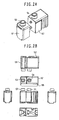
- Figs. 2A and 2B show the first embodiment of the reagent container for the automatic analyzer.
- a first reagent container 51 is provided with recesses or projections formed in its side surface
- a second reagent container 52 is provided with projections or recesses formed in its side surface.
- the recesses or projections of the first reagent container 51 and the projections or recesses of the second reagent container 52 can be jointed to each other in a not easy separable manner in such a state that the relative positional relationship between the first reagent container 51 and the second reagent container 52 is fixedly held.
- the reagent cassette 12 comprising the first and second reagent containers in the jointed state has outer dimensions defined such that the reagent cassette 12 can be placed in a reagent cassette holder on the reagent disk 26 without a play.
- an opening 53 of the first reagent container 51 and an opening 54 of the second reagent container 52 i.e., respective reagent sucking positions, are aligned with each other within a predetermined positional range on the basis of the outer dimensions of the reagent cassette 12.
- the first and second reagent containers are able to stand alone and are free from a risk of falling in a state of being filled with the reagents, they can be handled with high efficiency.
- a barcode label 55 is pasted to the reagent cassette 12 and contains information regarding the opening 53 of the first reagent container 51, the opening 54 of the second reagent container 52, the size of each reagent container, the kind of each reagent, the analysis parameters, the lot number, etc.
- the position at which the barcode label 55 is pasted is not limited to an upper surface, and it may be pasted to a side surface.
- the openings 53, 54 of the first reagent container 51 and the second reagent container 52 are shown as being positioned substantially at the centers of respective upper surfaces, they may be offset from the centers.
- Such an offset arrangement of the openings 53, 54 from the centers is effective in defining the insert direction of the reagent cassette 12 to be specific one in the combination of the reagent disk 26 and the reagent cassette holder, and hence in preventing false insertion of the reagent cassette 12.
- Dents having sizes comparable to the openings 53, 54 are formed in respective bottom portions of both the reagent containers in positions right below the openings 53, 54 of the first and second reagent containers 51, 52. The presence of the dent can reduce a reagent dead volume in each reagent container. Also, when the reagent disk is rotated at high speeds, the presence of the dent is effective in reducing the influence of a centrifugal force. In particular, such a structure is advantageous when the amount of reagent is small.
- a reagent container having outer dimensions and openings in match with those of the two reagent containers may be formed in the case of using one kind of reagent.
- a corresponding number of reagent containers may be jointed together in the same manner as described above such that respective openings of the reagent containers are aligned in a straight line with certain intervals.
- each reagent container has two circular projections or recesses as joint portions
- the number of joint portions may be one.
- the barcode label or the like may be pasted so as to extend over the upper surfaces of the two reagent containers, or the joint portion may be formed into a polygonal shape, e.g., a triangular or quadrangular shape.
- those joint portions may have shapes different from each other.
- one joint portion may have a circular shape and the other joint portion may have a quadrangular shape.
- the reagent container is molded using a plastic such as polyethylene, it is preferable that the reagent container has a shape as simple as possible and has projections or recesses as less as possible.
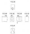
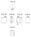
- Figs. 6A to 8F are explanatory views showing other projection forms of the second reagent container 52 when the joint portions have triangular, quadrangular and other shapes.
- Figs. 6A to 6F show the example in which one projection of the second reagent container 52 has a triangular shape and the other projection has a quadrangular shape.
- Figs. 7A to 7F show the example in which one projection of the second reagent container 52 has a circular shape and the other projection has a quadrangular shape.
- Figs. 8A to 8F show the example in which the projections of the second reagent container 52 each have a quadrangular shape.
- a featured portion (partial design) is indicated by solid lines within a one-dot-chain line box, and similar portions to those in the above-described embodiment are indicated by dotted lines. Note that the portions indicated by dotted lines slightly differ from corresponding portions of the second reagent container 52 shown in Figs. 2A and 2B in some areas.
- Fig. 6A, 6B, 6C, 6D, 6E and 6F are respectively a plan view, a left side view, a front view, a right side view, a rear view, and a bottom view.
- Figs. 7A), 7B, 7C, 7D, 7E and 7F are respectively a plan view, a left side view, a front view, a right side view, a rear view, and a bottom view.
- Figs. 8A, 8B, 8C, 8D, 8E and 8F are respectively a plan view, a left side view, a front view, a right side view, a rear view, and a bottom view.
- Figs. 3A and 3B show the second embodiment of the reagent container for the automatic analyzer according to the present invention.
- a first reagent container 51 and a second reagent container 52 both constituting a reagent cassette 12 are the same as those shown in Figs. 2A and 2B.
- a reinforcement member 56 is disposed over upper surfaces of the first reagent container 51 and the second reagent container 52.
- the reinforcement member 56 serves to not only reinforce the joint between the first reagent container 51 and the second reagent container 52, but also to exactly define the outer dimensions of the reagent cassette and to increase accuracy in positioning of the openings 53, 54 of the first reagent container 51 and the second reagent container 52. While Fig.
- FIG 3 shows the case in which the reinforcement member 56 is disposed over the upper surfaces of the first reagent container 51 and the second reagent container 52, a reinforcement member may be disposed at bottom portions of both the reagent containers for the same purposes.
- the other constructions and functions of the reagent cassette and the reagent containers are the same as those in the first embodiment.
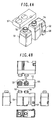
- Figs. 4A and 4B show the third embodiment of the reagent container for the automatic analyzer.
- This third embodiment comprises a first reagent container 51, a second reagent container 52, and a container holder 57, which cooperatively constitute a reagent cassette 12. Neither recesses nor projections used for jointing are provided in or on side surfaces of the first reagent container 51 and the second reagent container 52, and both the reagent containers are held together by the container holder 57.
- the container holder 57 serves to not only hold both the reagent containers together, but also to exactly define the outer dimensions and the positions of the openings 53, 54 when the first reagent container 51 and the second reagent container 52 are held together.
- a boss 58 is provided on a part of a side surface of the first reagent container or the second reagent container.
- Figs. 4A and 4B show the case in which the container holder 57 is fitter over upper portions of both the reagent containers, it may be fitted over bottom portions of both the reagent containers.
- the other constructions and functions of the reagent cassette and the reagent containers are the same as those in the first embodiment.
- Figs. 5A and 5B show the fourth embodiment of the reagent container for the automatic analyzer.
- the constructions and functions of the reagent cassette and the reagent container in this embodiment are the same as those in the first embodiment.
- the volumes of the first reagent container 51 and the second reagent container 52 are modified.
- the outer dimensions of the reagent cassette and the positions of the openings 53 in the jointed state are maintained by combinations of recesses and projections as in the first embodiment.
- the reagent containers 51 and the second reagent container 52 are jointed to each other, high flexibility is given in selecting the reagent volume. So long as the outer dimensions and the positions of the openings in the jointed state are maintained, the reagent containers having different volumes can be freely combined with each other depending on the amounts of required reagents. Further, the method of jointing the reagent containers is not limited to the combinations of recesses and projections or the use of a container holder, and the reagent containers may be jointed together by bonding or tape binding. A barcode level is also preferably used to joint the reagent containers together.
Landscapes
- Chemical & Material Sciences (AREA)
- Health & Medical Sciences (AREA)
- Analytical Chemistry (AREA)
- Chemical Kinetics & Catalysis (AREA)
- Physics & Mathematics (AREA)
- Life Sciences & Earth Sciences (AREA)
- Clinical Laboratory Science (AREA)
- Biochemistry (AREA)
- General Health & Medical Sciences (AREA)
- General Physics & Mathematics (AREA)
- Immunology (AREA)
- Pathology (AREA)
- Engineering & Computer Science (AREA)
- Mechanical Engineering (AREA)
- Automatic Analysis And Handling Materials Therefor (AREA)
Claims (7)
- Kombination von Reagenzbehältern, einzusetzen in ein Reaktionstablett einer automatischen Analysevorrichtung und umfassend
mindestens zwei Reagenzbehälter (51, 52), die jeweils ein Reagens beinhalten können und mindestens eine abdichtbare Öffnung (53, 54) umfassen, und
ein Aufzeichnungselement (55) für Identifikationsinformation zum Identifizieren von in den Reagenzbehältern (51, 52) enthaltenen Reagenzien,
wobei jeder der Reagenzbehälter (51, 52) einen Verbindungsabschnitt aufweist, der es ermöglicht, daß die mindestens zwei Reagenzbehälter unmittelbar miteinander verbunden werden können,
dadurch gekennzeichnet, daß
die Kombination ferner ein Verstärkungselement (56) umfaßt und
das Aufzeichnungselement (55) für Identifikationsinformation und das Verstärkungselement (56) so positioniert sind, daß sie über die oberen Flächen der Reagenzbehälter (51, 52) verlaufen, wenn die Reagenzbehälter (51, 52) über die Verbindungsabschnitte unmittelbar miteinander verbunden sind. - Kombination nach Anspruch 1, wobei das Verstärkungselement (56) dazu ausgelegt ist, die Trennung der Reagenzbehälter (51, 52) zu verhindern, wenn sie über die Verbindungsabschnitte unmittelbar miteinander verbunden sind.
- Kombination nach Anspruch 1, wobei die Höhen der Reagenzbehälter (51, 52) im wesentlichen gleich sind.
- Kombination nach Anspruch 1, wobei der Verbindungsabschnitt eines Reagenzbehälters eine ausgesparte Form aufweist und der Verbindungsabschnitt eines anderen Reagenzbehälters eine hervorspringende Form aufweist.
- Kombination nach Anspruch 4, wobei der Verbindungsabschnitt für jeden Reagenzbehälter (51, 52) an mindestens zwei Stellen vorgesehen ist.
- Kombination nach Anspruch 5, wobei die an mindestens zwei Stellen geformten Verbindungsabschnitte für jeden Reagenzbehälter (51, 52) voneinander verschiedene Formen aufweisen.
- Kombination nach Anspruch 1, wobei jeder Reagenzbehälter (51, 52) ferner einen Identifikationsabschnitt zum Identifizieren einer Richtung aufweist, in der der Reagenzbehälter eingesetzt wird, wenn die Reagenzbehälter über die Verbindungsabschnitte unmittelbar miteinander verbunden werden.
Applications Claiming Priority (2)
| Application Number | Priority Date | Filing Date | Title |
|---|---|---|---|
| JP2003406682 | 2003-12-05 | ||
| JP2003406682A JP2005164509A (ja) | 2003-12-05 | 2003-12-05 | 試薬容器 |
Publications (3)
| Publication Number | Publication Date |
|---|---|
| EP1538447A2 EP1538447A2 (de) | 2005-06-08 |
| EP1538447A3 EP1538447A3 (de) | 2006-04-26 |
| EP1538447B1 true EP1538447B1 (de) | 2007-10-31 |
Family
ID=34464011
Family Applications (1)
| Application Number | Title | Priority Date | Filing Date |
|---|---|---|---|
| EP04028351A Expired - Lifetime EP1538447B1 (de) | 2003-12-05 | 2004-11-30 | Reagenzbehälter |
Country Status (5)
| Country | Link |
|---|---|
| US (1) | US20050142040A1 (de) |
| EP (1) | EP1538447B1 (de) |
| JP (1) | JP2005164509A (de) |
| CN (1) | CN1624485A (de) |
| DE (1) | DE602004009744T2 (de) |
Families Citing this family (38)
| Publication number | Priority date | Publication date | Assignee | Title |
|---|---|---|---|---|
| US7447493B2 (en) * | 2003-02-28 | 2008-11-04 | Silicon Laboratories, Inc. | Tuner suitable for integration and method for tuning a radio frequency signal |
| US7425995B2 (en) * | 2003-02-28 | 2008-09-16 | Silicon Laboratories, Inc. | Tuner using a direct digital frequency synthesizer, television receiver using such a tuner, and method therefor |
| WO2006123660A1 (ja) * | 2005-05-17 | 2006-11-23 | Wako Pure Chemical Industries, Ltd. | 連結試薬容器 |
| EP1808698A1 (de) * | 2006-01-13 | 2007-07-18 | F.Hoffmann-La Roche Ag | Reagenzkit und Analysator |
| JP4787026B2 (ja) * | 2006-01-20 | 2011-10-05 | 凸版印刷株式会社 | 反応容器 |
| FR2904114B1 (fr) * | 2006-07-21 | 2008-10-17 | Biocode Hycel France Sa Sa | Cartouche pour produits reactifs destinee a etre utilisee da dans des apprareils d'analyse, portoir destine a recevoir cette cartouche, et ensemble d'analyse comprenant cette cartouche et ce portoir |
| DE202006017454U1 (de) * | 2006-11-14 | 2007-05-16 | Diasys Technologies S.A.R.L. | Reagenzienbehälter und Reagenzienkarussell |
| JP2008180639A (ja) * | 2007-01-25 | 2008-08-07 | Olympus Corp | 試薬容器 |
| CN101815948B (zh) | 2007-09-28 | 2014-03-26 | 霍夫曼-拉罗奇有限公司 | 试剂容器系统 |
| CN102066949B (zh) * | 2008-06-17 | 2013-06-12 | 株式会社日立高新技术 | 自动分析装置 |
| USD630765S1 (en) * | 2008-09-01 | 2011-01-11 | Roche Diagnostics Operations, Inc. | Container for liquids |
| CA2745732C (en) * | 2008-12-05 | 2014-02-11 | F. Hoffmann-La Roche Ag | Method for producing a reagent container assembly and reagent container assembly |
| JP5161747B2 (ja) * | 2008-12-12 | 2013-03-13 | 株式会社東芝 | 試薬容器、自動分析装置、及び試薬管理方法 |
| USD632402S1 (en) * | 2009-02-19 | 2011-02-08 | Roche Diagnostics Operations, Inc. | Combination of reagent holder and parts |
| USD634441S1 (en) | 2009-02-19 | 2011-03-15 | Roche Diagnostics Operations, Inc. | Reagent holder tube |
| US8435454B2 (en) * | 2009-07-09 | 2013-05-07 | Siemens Medical Solutions Usa, Inc. | Modular system for radiosynthesis with multi-run capabilities and reduced risk of radiation exposure |
| USD644741S1 (en) | 2009-08-19 | 2011-09-06 | Roche Diagnostics Operations, Inc. | Reagent holder tube |
| USD637731S1 (en) * | 2009-08-19 | 2011-05-10 | Roche Diagnostics Operations, Inc. | Combination of reagent holder and part |
| EP3783368A1 (de) * | 2010-02-26 | 2021-02-24 | Sysmex Corporation | Reagenzienbehälter |
| EP2371731A1 (de) | 2010-03-31 | 2011-10-05 | Roche Diagnostics GmbH | Reagenz-Kit mit Transportsicherung |
| JP2013535193A (ja) | 2010-07-23 | 2013-09-12 | ベックマン コールター, インコーポレイテッド | 分析装置を含むシステムおよび方法 |
| JP5537640B2 (ja) * | 2012-12-07 | 2014-07-02 | 株式会社東芝 | 試薬容器及び試薬管理方法 |
| JP6494914B2 (ja) | 2013-02-15 | 2019-04-03 | キヤノンメディカルシステムズ株式会社 | 自動分析装置 |
| ES2942031T3 (es) | 2013-03-11 | 2023-05-29 | Meso Scale Technologies Llc | Métodos mejorados para realizar ensayos multiplexados |
| US10058866B2 (en) * | 2013-03-13 | 2018-08-28 | Abbott Laboratories | Methods and apparatus to mitigate bubble formation in a liquid |
| USD978375S1 (en) | 2013-03-13 | 2023-02-14 | Abbott Laboratories | Reagent container |
| USD962471S1 (en) | 2013-03-13 | 2022-08-30 | Abbott Laboratories | Reagent container |
| US9535082B2 (en) | 2013-03-13 | 2017-01-03 | Abbott Laboratories | Methods and apparatus to agitate a liquid |
| CN114137240A (zh) | 2013-03-15 | 2022-03-04 | 雅培制药有限公司 | 具有后面可进入轨道系统的自动化诊断分析仪及相关方法 |
| USD765875S1 (en) * | 2013-10-25 | 2016-09-06 | Sysmex Corporation | Reagent set |
| USD747813S1 (en) * | 2014-05-27 | 2016-01-19 | Beckman Coulter, Inc. | Bottle |
| IES86617B2 (en) | 2014-05-27 | 2016-01-27 | Beckman Coulter Inc | Reagent bottle with aspiration pipe |
| WO2016130962A1 (en) | 2015-02-13 | 2016-08-18 | Abbott Laboratories | Automated storage modules for diagnostic analyzer liquids and related systems and methods |
| USD769456S1 (en) * | 2015-02-20 | 2016-10-18 | Siemens Healthcare Diagnostics Inc. | Reagent pack |
| CN104849440B (zh) * | 2015-05-28 | 2017-07-11 | 万华普曼生物工程有限公司 | 带有防误装结构的采集检测一体装置 |
| WO2018181646A1 (ja) * | 2017-03-31 | 2018-10-04 | 積水メディカル株式会社 | 試薬容器用アダプタ |
| KR102849162B1 (ko) * | 2018-12-14 | 2025-08-22 | 라이카 바이오시스템즈 멜버른 피티와이 엘티디 | 시약 카세트 |
| CN112067830B (zh) * | 2019-06-10 | 2025-12-12 | 深圳迈瑞生物医疗电子股份有限公司 | 凝血试剂管理方法和系统 |
Family Cites Families (18)
| Publication number | Priority date | Publication date | Assignee | Title |
|---|---|---|---|---|
| US3194426A (en) * | 1963-12-12 | 1965-07-13 | Jr Lynn E Brown | Laterally interlocked containers |
| JPS4730943Y1 (de) * | 1969-12-10 | 1972-09-16 | ||
| US4656840A (en) * | 1985-11-29 | 1987-04-14 | Gott Corporation | Container for freezable liquid |
| JPS6352741U (de) * | 1986-09-25 | 1988-04-09 | ||
| DE4313807C2 (de) * | 1992-04-28 | 1995-03-09 | Olympus Optical Co | Reagenz-Container-System für die immunologische Analyse einer Probe in einem automatischen Analysiergerät |
| JPH05302924A (ja) * | 1992-04-28 | 1993-11-16 | Olympus Optical Co Ltd | 自動分析機用試薬容器 |
| CA2100434A1 (en) * | 1992-07-14 | 1994-01-15 | Charles Eumurian | Specimen tube transfer carrier |
| US5534224A (en) * | 1993-07-16 | 1996-07-09 | Fuji Photo Film Co., Ltd. | Chemical analysis film cartridge |
| DE4425277A1 (de) * | 1994-07-16 | 1996-01-18 | Boehringer Mannheim Gmbh | Verpackungssystem für Flüssigreagenzien |
| JPH08192848A (ja) * | 1995-01-05 | 1996-07-30 | Onishi Kasei Kk | 集合容器 |
| JPH08271525A (ja) * | 1995-03-29 | 1996-10-18 | Suzuki Motor Corp | 酵素免疫反応測定装置 |
| DE19540877C2 (de) * | 1995-11-02 | 1998-02-26 | Byk Sangtec Diagnostica | Modulare Reagenzienkartusche |
| AR005745A4 (es) * | 1997-02-07 | 1999-07-14 | Fascio Silva Mirta Liliana | Envase modular interconectable, de usos multiples |
| JP4542287B2 (ja) * | 2000-03-31 | 2010-09-08 | シスメックス株式会社 | 試薬容器開閉ユニット及びバーコード貼付ユニット |
| JP4615135B2 (ja) * | 2000-03-31 | 2011-01-19 | シスメックス株式会社 | 試薬分注装置及びそれを用いた検体自動分析装置 |
| JP2002046746A (ja) * | 2000-08-02 | 2002-02-12 | Kitto:Kk | ポリタンク |
| US7666363B2 (en) * | 2001-09-05 | 2010-02-23 | Quest Diagnostics Investments Incorporated | Reagent cartridge |
| JP4146780B2 (ja) * | 2003-10-17 | 2008-09-10 | 株式会社日立ハイテクノロジーズ | 試薬カセット及びそれを用いる自動分析装置 |
-
2003
- 2003-12-05 JP JP2003406682A patent/JP2005164509A/ja active Pending
-
2004
- 2004-11-30 EP EP04028351A patent/EP1538447B1/de not_active Expired - Lifetime
- 2004-11-30 DE DE602004009744T patent/DE602004009744T2/de not_active Expired - Lifetime
- 2004-12-02 CN CN200410095605.XA patent/CN1624485A/zh active Pending
- 2004-12-03 US US11/002,084 patent/US20050142040A1/en not_active Abandoned
Also Published As
| Publication number | Publication date |
|---|---|
| DE602004009744D1 (de) | 2007-12-13 |
| EP1538447A2 (de) | 2005-06-08 |
| JP2005164509A (ja) | 2005-06-23 |
| EP1538447A3 (de) | 2006-04-26 |
| US20050142040A1 (en) | 2005-06-30 |
| DE602004009744T2 (de) | 2008-08-28 |
| CN1624485A (zh) | 2005-06-08 |
Similar Documents
| Publication | Publication Date | Title |
|---|---|---|
| EP1538447B1 (de) | Reagenzbehälter | |
| CN101661045B (zh) | 组合试剂容器及使用该组合试剂容器的自动分析装置 | |
| US5424036A (en) | Automatic analyzer | |
| EP2916135B1 (de) | Reagenzienbehälter und automatischer analysator | |
| EP3267203B1 (de) | Probenanalysator | |
| US5757666A (en) | System for analyzing compounds contained liquid samples | |
| US20040033163A1 (en) | Automated tissue staining system and reagent container | |
| JPH0588427B2 (de) | ||
| CA2287364A1 (en) | Analysis system | |
| CA2462484C (en) | Analyzer having a stationary multifunction probe | |
| CA2836348C (en) | Method for holding multiple types of diagnostic test consumables in a random access single container | |
| KR20040097953A (ko) | 분석기와, 샘플 분석 방법과, 구성요소 이송 방법 및데스크탑형 분석기용 액체 이송 시스템 | |
| JP2004301844A (ja) | 分析装置用プローブガイド付き検査要素ホルダー | |
| JP4891749B2 (ja) | 自動分析装置 | |
| JPH05302924A (ja) | 自動分析機用試薬容器 | |
| JPS6168562A (ja) | 液体試料分析装置 | |
| JP2010139412A (ja) | 試薬容器、自動分析装置、及び試薬管理方法 | |
| JPS6218870B2 (de) | ||
| JP5537640B2 (ja) | 試薬容器及び試薬管理方法 | |
| JP2009281988A (ja) | 自動分析装置及びその管理方法 | |
| CZ370299A3 (cs) | Analyzační systém, analyzační přístroj a systémový nosič reagencií, zejména pro tento analyzační systém |
Legal Events
| Date | Code | Title | Description |
|---|---|---|---|
| PUAI | Public reference made under article 153(3) epc to a published international application that has entered the european phase |
Free format text: ORIGINAL CODE: 0009012 |
|
| AK | Designated contracting states |
Kind code of ref document: A2 Designated state(s): AT BE BG CH CY CZ DE DK EE ES FI FR GB GR HU IE IS IT LI LU MC NL PL PT RO SE SI SK TR |
|
| AX | Request for extension of the european patent |
Extension state: AL HR LT LV MK YU |
|
| PUAL | Search report despatched |
Free format text: ORIGINAL CODE: 0009013 |
|
| AK | Designated contracting states |
Kind code of ref document: A3 Designated state(s): AT BE BG CH CY CZ DE DK EE ES FI FR GB GR HU IE IS IT LI LU MC NL PL PT RO SE SI SK TR |
|
| AX | Request for extension of the european patent |
Extension state: AL HR LT LV MK YU |
|
| 17P | Request for examination filed |
Effective date: 20060331 |
|
| 17Q | First examination report despatched |
Effective date: 20060725 |
|
| AKX | Designation fees paid |
Designated state(s): DE FR |
|
| GRAP | Despatch of communication of intention to grant a patent |
Free format text: ORIGINAL CODE: EPIDOSNIGR1 |
|
| GRAS | Grant fee paid |
Free format text: ORIGINAL CODE: EPIDOSNIGR3 |
|
| GRAA | (expected) grant |
Free format text: ORIGINAL CODE: 0009210 |
|
| AK | Designated contracting states |
Kind code of ref document: B1 Designated state(s): DE FR |
|
| REF | Corresponds to: |
Ref document number: 602004009744 Country of ref document: DE Date of ref document: 20071213 Kind code of ref document: P |
|
| ET | Fr: translation filed | ||
| PLBE | No opposition filed within time limit |
Free format text: ORIGINAL CODE: 0009261 |
|
| STAA | Information on the status of an ep patent application or granted ep patent |
Free format text: STATUS: NO OPPOSITION FILED WITHIN TIME LIMIT |
|
| 26N | No opposition filed |
Effective date: 20080801 |
|
| REG | Reference to a national code |
Ref country code: FR Ref legal event code: PLFP Year of fee payment: 12 |
|
| REG | Reference to a national code |
Ref country code: FR Ref legal event code: PLFP Year of fee payment: 13 |
|
| REG | Reference to a national code |
Ref country code: FR Ref legal event code: PLFP Year of fee payment: 14 |
|
| REG | Reference to a national code |
Ref country code: FR Ref legal event code: PLFP Year of fee payment: 15 |
|
| REG | Reference to a national code |
Ref country code: DE Ref legal event code: R082 Ref document number: 602004009744 Country of ref document: DE Representative=s name: STREHL SCHUEBEL-HOPF & PARTNER MBB PATENTANWAE, DE Ref country code: DE Ref legal event code: R081 Ref document number: 602004009744 Country of ref document: DE Owner name: HITACHI HIGH-TECH CORPORATION, JP Free format text: FORMER OWNER: HITACHI HIGH-TECHNOLOGIES CORPORATION, TOKYO, JP |
|
| PGFP | Annual fee paid to national office [announced via postgrant information from national office to epo] |
Ref country code: FR Payment date: 20201013 Year of fee payment: 17 Ref country code: DE Payment date: 20201118 Year of fee payment: 17 |
|
| REG | Reference to a national code |
Ref country code: DE Ref legal event code: R119 Ref document number: 602004009744 Country of ref document: DE |
|
| PG25 | Lapsed in a contracting state [announced via postgrant information from national office to epo] |
Ref country code: DE Free format text: LAPSE BECAUSE OF NON-PAYMENT OF DUE FEES Effective date: 20220601 |
|
| PG25 | Lapsed in a contracting state [announced via postgrant information from national office to epo] |
Ref country code: FR Free format text: LAPSE BECAUSE OF NON-PAYMENT OF DUE FEES Effective date: 20211130 |