EP1538427A2 - Druck-Federelement zum Anschluss eines Kabels an einen Messwertaufnehmer - Google Patents
Druck-Federelement zum Anschluss eines Kabels an einen Messwertaufnehmer Download PDFInfo
- Publication number
- EP1538427A2 EP1538427A2 EP04026886A EP04026886A EP1538427A2 EP 1538427 A2 EP1538427 A2 EP 1538427A2 EP 04026886 A EP04026886 A EP 04026886A EP 04026886 A EP04026886 A EP 04026886A EP 1538427 A2 EP1538427 A2 EP 1538427A2
- Authority
- EP
- European Patent Office
- Prior art keywords
- cable
- housing
- sensor
- spring element
- compression spring
- Prior art date
- Legal status (The legal status is an assumption and is not a legal conclusion. Google has not performed a legal analysis and makes no representation as to the accuracy of the status listed.)
- Granted
Links
- 230000006835 compression Effects 0.000 title claims abstract description 14
- 238000007906 compression Methods 0.000 title claims abstract description 14
- 239000012815 thermoplastic material Substances 0.000 claims abstract 2
- 239000000463 material Substances 0.000 claims description 3
- 239000013013 elastic material Substances 0.000 claims 1
- 239000002184 metal Substances 0.000 claims 1
- 210000004907 gland Anatomy 0.000 description 18
- 230000006378 damage Effects 0.000 description 3
- 230000000694 effects Effects 0.000 description 3
- 229920001971 elastomer Polymers 0.000 description 3
- 239000000806 elastomer Substances 0.000 description 3
- 239000000523 sample Substances 0.000 description 3
- 238000007789 sealing Methods 0.000 description 3
- 238000009423 ventilation Methods 0.000 description 3
- 239000004033 plastic Substances 0.000 description 2
- 239000004020 conductor Substances 0.000 description 1
- 238000009434 installation Methods 0.000 description 1
- 239000007788 liquid Substances 0.000 description 1
- 230000002522 swelling effect Effects 0.000 description 1
- 229920001169 thermoplastic Polymers 0.000 description 1
- 239000004416 thermosoftening plastic Substances 0.000 description 1
Images
Classifications
-
- G—PHYSICS
- G01—MEASURING; TESTING
- G01F—MEASURING VOLUME, VOLUME FLOW, MASS FLOW OR LIQUID LEVEL; METERING BY VOLUME
- G01F23/00—Indicating or measuring liquid level or level of fluent solid material, e.g. indicating in terms of volume or indicating by means of an alarm
-
- H—ELECTRICITY
- H01—ELECTRIC ELEMENTS
- H01R—ELECTRICALLY-CONDUCTIVE CONNECTIONS; STRUCTURAL ASSOCIATIONS OF A PLURALITY OF MUTUALLY-INSULATED ELECTRICAL CONNECTING ELEMENTS; COUPLING DEVICES; CURRENT COLLECTORS
- H01R13/00—Details of coupling devices of the kinds covered by groups H01R12/70 or H01R24/00 - H01R33/00
- H01R13/46—Bases; Cases
- H01R13/52—Dustproof, splashproof, drip-proof, waterproof, or flameproof cases
- H01R13/5205—Sealing means between cable and housing, e.g. grommet
Definitions
- the invention relates to a transducer, in particular a level sensor, pressure transmitter or the like, with a sensor receiving housing and one of the Housing detachable and can be introduced into the housing grommet, wherein the cable gland at least one molded seal having.
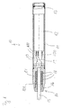
- Fig. 1 shows a known from the prior art transducers 10 with a housing 11 in which an electronic Transmitter 12 and a sensor 13 are housed. Furthermore, the transducer 10 has a cable feedthrough 14 for carrying a cable 15 on.
- the cable entry 14 may be an elastomeric molded gasket 17 or a plurality of elastomeric molded gaskets 18, which by a pressure screw 16th be compressed. From the cable 15 come wires 19, by means of Plug-in elements 100, as butt connectors, tabs or wire end sleeves can be formed on the electronic Transmitter 12 are inserted.
- Plug-in elements 100 as butt connectors, tabs or wire end sleeves can be formed on the electronic Transmitter 12 are inserted.
- To improve the Tightness of the elastomeric form seals 17 and 18 are common glued to the cable 15 and a cable receptacle 101.
- the bonded elastomeric form seals 17 and 18 forcibly damaged, so they are no longer are used and must be replaced with new ones. If on a bond between the cable 15 and the elastomeric seals 17 and 18 and the cable receptacle 101 omitted can, the elastomeric form densities 17 and 18 in the course of Time on both the cable 15 and the cable receptacle 101 firm enough so that the elastomer seals 17 and 18 during disassembly of the cable gland 14 also inevitable be destroyed.
- the invention has the task of a transducer of to improve the type mentioned above in the future the molded gasket is not damaged during disassembly or assembly becomes.
- the invention solves the task by a transducer of the aforementioned type, the invention thereby is characterized in that the at least one molded seal surrounded by a cable feedthrough housing. Consequently The at least one molded gasket can not be disassembled or mounting the cable gland on the housing of the sensor stick or rub, causing damage the reliably excluded at least one molded seal is and the seal between the cable and the at least one molded seal remains unchanged. Consequently can, for example, in case of service with the cable gland connected electrical connection quickly and easily be transferred to another transducer.
- a spring element e.g. a compression spring
- the spring element compresses the cable enclosing at least one molded seal and thus increases the sealing effect of the at least one molded seal.
- a compression spring receiving spring housing be screwed.
- connection sockets connected to them At the free end of the spring housing electrical plug connections be attached rigidly with the cable gland are connected and thus also in a demotage of the cable gland with applied electrical supply voltage Short-circuit proof from the connection sockets connected to them can be pulled out.
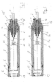
- FIG. 2 shows the measuring transducer according to the invention.
- the sensor has a tubular sensor housing 8 on with an arranged therein, electronic transmitter 11, wherein this electronic transmitter 11 at the in the figure 2 right side of a socket housing 9 and a pin tray 10 to a connection cable 1 in still can be connected to an explanatory manner.
- the electronic Transmitter 11 points to the opposite side a sensor element 12, which in a cylindrical Housing part 13 is seated.
- This cylindrical housing part 13th is O-ring seals 6 on the one hand with the sensor housing. 8 sealingly connected and the other with the pressure sensor 12th
- the housing part 13 and the sensor housing part 8 can, for example be screwed together. Other mounting options are also possible.
- connection cable 1 is on stripped of its front end so that an inner conductor the mentioned socket housing 9 is connected.
- This socket housing 9 is intended for a suitable plug connection of the electrical transmitter 11 attached to become.
- connection cable 1 has at its front, free end via an internal ventilation cable 1a. This ventilation cable 1a is optional and does not have to be provided.
- a cable receptacle 2 To the connection cable 1 around sits a cable receptacle 2, the is preferably formed of plastic material. For reasons of elasticity is in this cable receptacle 2 an annular and incorporated concentric opening to the axis of the cable 1, in which preferably a metallic support ring sits.
- the Cable holder 2 also has a centric, conical widening opening, within which a correspondingly conical extending support sleeve 3 is seated.
- the cable 1 is like this prepared that the cable sheath 1b in the mounted state between the wall of the cable receptacle 2 and the outer wall the conically extending support sleeve 3 is clamped.
- a compression spring element 4 here as a cylindrical, elastic Part is executed, arranged.
- a spring housing 5 To this compression spring element 4th around is a spring housing 5.
- This spring housing 5 closes flush with the above-mentioned annular sleeve 15 at.
- the spring housing 5 also integral with the annular sleeve 15th be made.
- the spring housing 5 engages on his in Figure 2 and Figure 3 left edge shown around the compression spring element 4 around and sits down sleeve-shaped with a reduced Diameter to the socket housing 9 away.
- the spring housing 5 moreover, one half of its extension follows one outside leaping, encircling hexagon 5a at the same time a stop for the cable housing 2 and as a month mate serves.
- the cable receiving housing 2 has a circumferential, annular groove in which sits another O-ring.
- thermoplastic housing As with conventional cable seals is the case, be avoided can.
- connection cable 1 which was previously installed in another transducer, not crushed. This will prevent the ingress of media, such as z. As liquids, effectively prevented in the probe.
- the temperature of the medium can reach the temperature limit the electronics can and are operated Media measured with the transducer according to the invention are, despite the swelling effect of the plastic does not lead to failure lead the probe.
- the probe can after of the invention are operated in media in which elastomers the cable seal are not resistant, since molded seals made of high quality elastomeric materials, such as Kalrez not Available from stock and therefore in relation to the device price are not marketable.
Landscapes
- Physics & Mathematics (AREA)
- Fluid Mechanics (AREA)
- General Physics & Mathematics (AREA)
- Measuring Fluid Pressure (AREA)
Abstract
Description
- Fig. 1
- einen Längsschnitt durch einen aus dem Stand der Technik bekannten Messwertaufnehmer;
- Fig. 2
- einen Längsschnitt durch einen ersten erfindungsgemäßen Messwertaufnehmer und
- Fig. 3
- einen Längsschnitt durch einen zweiten erfindungsgemäßen Messwertaufnehmer.
Claims (6)
- Füllstandmesswertaufnehmer mit einem einen Sensor (11, 12) aufnehmenden Gehäuse (8), durch dessen eine Öffnung ein Anschlusskabel (1) zum Anschließen an den Sensor (11, 12) vorgesehen ist und wobei das Anschlusskabel (1) von einem Druck-Federelement (4) umgeben ist,
dadurch gekennzeichnet, dass neben dem Druck-Federelement (4) eine konische Stützhülse (3) angeordnet ist und ein Kabelaufnahmegehäuse (2) aus thermoplastischem Material mit einer konischen Öffnung vorgesehen ist, in welcher die konische Stützhülse (3) eingreift und wobei zwischen der konischen Stützhülse (3) und dem Kabelaufnahmegehäuse (2) ein Kabelmantel (1b) des Anschlusskabels (1) eingeklemmt ist, wobei das Druckfederelement (4) von einem Federgehäuse (5) umgeben ist und das Kabelaufnahmegehäuse (2) mittels Überwurfhülse (7) an dem Sensorgehäuse (8) festlegbar ist. - Messwertaufnehmer nach Anspruch 1,
dadurch gekennzeichnet, dass in dem Kabelaufnahmegehäuse (2) ein Stützring, vorzugsweise aus Metall, angeordnet ist. - Messwertaufnehmer nach Anspruch 2,
dadurch gekennzeichnet, dass das Federgehäuse (5) und der Stützring einstückig ausgebildet sind. - Messwertaufnehmer nach einem der Ansprüche 1 bis 3,
dadurch gekennzeichnet, dass das Stützring aus einem Werkstoff besteht, der eine größere Festigkeit als das Kabelaufnahmegehäuse (2) hat. - Messwertaufnehmer nach einem der Ansprüche 1 bis 4,
dadurch gekennzeichnet, dass das Druckfederelement (4) als Spiralfeder ausgebildet ist. - Messwertaufnehmer nach einem der Ansprüche 1 bis 5,
dadurch gekennzeichnet, dass das Druckfederelement (4) ein zylindrisches Teil aus einem elastischen Werkstoff ist.
Applications Claiming Priority (2)
| Application Number | Priority Date | Filing Date | Title |
|---|---|---|---|
| DE10357041 | 2003-12-04 | ||
| DE10357041A DE10357041A1 (de) | 2003-12-04 | 2003-12-04 | Messwertaufnehmer |
Publications (3)
| Publication Number | Publication Date |
|---|---|
| EP1538427A2 true EP1538427A2 (de) | 2005-06-08 |
| EP1538427A3 EP1538427A3 (de) | 2007-02-14 |
| EP1538427B1 EP1538427B1 (de) | 2015-04-22 |
Family
ID=34442479
Family Applications (1)
| Application Number | Title | Priority Date | Filing Date |
|---|---|---|---|
| EP20040026886 Expired - Lifetime EP1538427B1 (de) | 2003-12-04 | 2004-11-12 | Druck-Federelement zum Anschluss eines Kabels an einen Messwertaufnehmer |
Country Status (4)
| Country | Link |
|---|---|
| US (1) | US7143646B2 (de) |
| EP (1) | EP1538427B1 (de) |
| CN (1) | CN100472185C (de) |
| DE (1) | DE10357041A1 (de) |
Cited By (2)
| Publication number | Priority date | Publication date | Assignee | Title |
|---|---|---|---|---|
| US7764866B2 (en) | 2004-12-10 | 2010-07-27 | Lg Electronics, Inc. | Recording medium, method for searching for content data from the recording medium, and method and apparatus for reproducing data from the recording medium |
| EP3045880A1 (de) * | 2015-01-14 | 2016-07-20 | VEGA Grieshaber KG | Grenzstandmessanordnung |
Families Citing this family (7)
| Publication number | Priority date | Publication date | Assignee | Title |
|---|---|---|---|---|
| EP2241344B1 (de) * | 2009-04-16 | 2013-12-11 | F. Hoffmann-La Roche AG | Tragbare Infusionsvorrichtung mit Sensortesteinheit |
| CN102044810B (zh) * | 2009-10-12 | 2013-10-30 | 西安威尔罗根能源科技有限公司 | 一种电子仪骨架的连接装置 |
| CN102680052B (zh) * | 2012-05-10 | 2013-10-30 | 苏州赛智达智能科技有限公司 | 电容式低温液位计的引出导线的连接结构 |
| CN105333939B (zh) * | 2015-11-27 | 2018-04-17 | 四川奇石缘科技股份有限公司 | 工字梁式车辆动态称重传感器的防水接头 |
| FR3055963B1 (fr) * | 2016-09-12 | 2018-08-24 | Pierre Payraud | Dispositif de fixation pour la tenue d'un capteur |
| CN111595301B (zh) * | 2020-05-20 | 2021-11-23 | 福建省伟志地理信息科学研究院 | 一种地理信息系统用航空测量装置及其测量方法 |
| DE102023205726A1 (de) | 2023-06-19 | 2024-12-19 | Vega Grieshaber Kg | Kabeldurchführung |
Family Cites Families (19)
| Publication number | Priority date | Publication date | Assignee | Title |
|---|---|---|---|---|
| US2460304A (en) * | 1944-07-29 | 1949-02-01 | Mcgee Kenneth | Connector |
| US3264602A (en) * | 1964-03-13 | 1966-08-02 | Automatic Metal Products Corp | Electrical connectors for coaxial cables |
| US3403671A (en) * | 1965-10-24 | 1968-10-01 | Magnaflux Corp | Ultrasonic transducer system |
| DE2744864B2 (de) * | 1977-10-05 | 1979-10-18 | Endress U. Hauser Gmbh U. Co, 7867 Maulburg | Vorrichtung zur Befestigung einer Sonde in einer öffnung eines Behälters |
| DE3215040C2 (de) * | 1982-04-22 | 1985-11-07 | VEGA Grieshaber -GmbH & Co, 7622 Schiltach | Resonanzstab |
| GB8601278D0 (en) * | 1986-01-20 | 1986-02-26 | British Telecomm | Clamp assembly |
| JPH0341434Y2 (de) * | 1986-09-17 | 1991-08-30 | ||
| DD287126A5 (de) * | 1989-08-02 | 1991-02-14 | Zft Inst Fuer Energieversorgun | Einrichtung fuer den elektrotechnischen anschluss von kabeln und leitungen an gefaesse mit hohen druck- und temperaturdifferenzen |
| JPH03148028A (ja) * | 1989-11-02 | 1991-06-24 | Matsushita Electric Ind Co Ltd | 圧電型圧力センサ |
| NL9000802A (nl) * | 1990-04-05 | 1991-11-01 | Texas Instruments Holland | Sensor voor het meten van de druk van een medium, in het bijzonder voor het meten van de wisselende druk in een dieselinspuitpomp. |
| DE19542650A1 (de) * | 1995-11-15 | 1997-05-22 | Bosch Gmbh Robert | Temperaturfeste Kabeldurchführung und Verfahren zu deren Herstellung |
| US6113429A (en) * | 1997-02-25 | 2000-09-05 | Dbt Automation Gmbh | Plug-type coupling for sheathed electrical cables |
| DE19728370A1 (de) * | 1997-07-03 | 1999-01-07 | Bosch Gmbh Robert | Kabeldurchführung für Anschlußkabel eines Gasmeßfühlers |
| EP1083414A1 (de) * | 1999-09-11 | 2001-03-14 | Endress + Hauser GmbH + Co. | Füllstandsmessgerät |
| US6711950B1 (en) * | 1999-11-30 | 2004-03-30 | Nippon Seiki Co., Ltd. | Liquid level detector |
| EP1126259B1 (de) * | 2000-02-15 | 2008-12-10 | Endress + Hauser GmbH + Co. KG | Drucksensor |
| DE10105544A1 (de) * | 2001-02-06 | 2003-01-09 | Endress & Hauser Gmbh & Co Kg | Kabeldurchführung |
| DE10212903B4 (de) * | 2002-03-22 | 2007-02-01 | Vega Grieshaber Kg | Messwertaufnehmer |
| DE10331967A1 (de) * | 2003-07-15 | 2005-02-03 | Robert Bosch Gmbh | Sensoreinrichtung |
-
2003
- 2003-12-04 DE DE10357041A patent/DE10357041A1/de not_active Withdrawn
-
2004
- 2004-11-12 EP EP20040026886 patent/EP1538427B1/de not_active Expired - Lifetime
- 2004-12-02 US US11/001,567 patent/US7143646B2/en not_active Expired - Lifetime
- 2004-12-03 CN CNB2004100983396A patent/CN100472185C/zh not_active Expired - Fee Related
Cited By (2)
| Publication number | Priority date | Publication date | Assignee | Title |
|---|---|---|---|---|
| US7764866B2 (en) | 2004-12-10 | 2010-07-27 | Lg Electronics, Inc. | Recording medium, method for searching for content data from the recording medium, and method and apparatus for reproducing data from the recording medium |
| EP3045880A1 (de) * | 2015-01-14 | 2016-07-20 | VEGA Grieshaber KG | Grenzstandmessanordnung |
Also Published As
| Publication number | Publication date |
|---|---|
| CN100472185C (zh) | 2009-03-25 |
| US7143646B2 (en) | 2006-12-05 |
| DE10357041A1 (de) | 2005-07-07 |
| EP1538427B1 (de) | 2015-04-22 |
| CN1624434A (zh) | 2005-06-08 |
| EP1538427A3 (de) | 2007-02-14 |
| US20060037391A1 (en) | 2006-02-23 |
Similar Documents
| Publication | Publication Date | Title |
|---|---|---|
| DE202017101060U1 (de) | Steckverbinder, insbesondere für eine Hochstromanwendung | |
| DE102007051836A1 (de) | Kabelsatz, insbesondere ein Hochvoltkabelsatz für ein Kraftfahrzeug, sowie eine Vorrichtung zur Durchführung eines elektrischen Kabels und zur Anbindung einer Abschirmung des Kabels | |
| EP2652840B1 (de) | Kabelverschraubung | |
| EP2609657A1 (de) | Kabelzugentlastung | |
| WO2018157962A1 (de) | Haltevorrichtung zum halten eines geschirmten kabels | |
| EP1538427B1 (de) | Druck-Federelement zum Anschluss eines Kabels an einen Messwertaufnehmer | |
| EP0638976A1 (de) | Muffenkopf für eine Kabelmuffe mit einem Dichtungseinsatz aus elastischem Material | |
| EP2184822B1 (de) | Tauchmotor | |
| DE102019005171A1 (de) | Elektromotor, insbesondere Außenläufermotor | |
| EP0908995B1 (de) | Kabelverschraubung für ein abgeschirmtes Kabel | |
| EP3574559A1 (de) | Kabeldurchführung mit abschirmenden und abdichtenden eigenschaften | |
| DE102013204832A1 (de) | Verbindungselement und Verbindungssystem für elektrische Leitungen | |
| DE10235212A1 (de) | Elektrischer Buchsenverbinder | |
| DE102008055841A1 (de) | Elektrisches Steckverbinderteil | |
| DE102008054585B4 (de) | Winkelsteckverbindung für geschirmte Kabel | |
| DE102014103436A1 (de) | Elektrischer Verbinder, elektrischer Anschluss, sowie elektrische Einrichtung oder Aggregat | |
| DE2932612C3 (de) | Kabelschirmerdung | |
| DE202006001904U1 (de) | Modulares Schutzgehäuse | |
| DE102014107425B4 (de) | Erdungsvorrichtung | |
| EP0034792A1 (de) | Anschlussvorrichtung für ein abgeschirmtes Kabel | |
| DE202011100829U1 (de) | Masseleiter-Verbindungssystem | |
| DE10212903B4 (de) | Messwertaufnehmer | |
| DE19546963A1 (de) | Anordnung zum Abdichten eines zylindrischen Körpers | |
| DE202005021422U1 (de) | Kabelsteckverbinder einer Steckverbindungseinrichtung für die Mittel- und Hochspannungstechnik | |
| DE69103115T2 (de) | Abgeschirmter, wasserdichter und elektrisch isolierter elektrischer Verbinder. |
Legal Events
| Date | Code | Title | Description |
|---|---|---|---|
| PUAI | Public reference made under article 153(3) epc to a published international application that has entered the european phase |
Free format text: ORIGINAL CODE: 0009012 |
|
| AK | Designated contracting states |
Kind code of ref document: A2 Designated state(s): AT BE BG CH CY CZ DE DK EE ES FI FR GB GR HU IE IS IT LI LU MC NL PL PT RO SE SI SK TR |
|
| AX | Request for extension of the european patent |
Extension state: AL HR LT LV MK YU |
|
| PUAL | Search report despatched |
Free format text: ORIGINAL CODE: 0009013 |
|
| AK | Designated contracting states |
Kind code of ref document: A3 Designated state(s): AT BE BG CH CY CZ DE DK EE ES FI FR GB GR HU IE IS IT LI LU MC NL PL PT RO SE SI SK TR |
|
| AX | Request for extension of the european patent |
Extension state: AL HR LT LV MK YU |
|
| RIC1 | Information provided on ipc code assigned before grant |
Ipc: G01F 23/00 20060101AFI20050405BHEP Ipc: H01R 13/52 20060101ALI20070110BHEP Ipc: G01D 11/24 20060101ALI20070110BHEP |
|
| 17P | Request for examination filed |
Effective date: 20070330 |
|
| AKX | Designation fees paid |
Designated state(s): DE FR GB |
|
| 17Q | First examination report despatched |
Effective date: 20091123 |
|
| GRAP | Despatch of communication of intention to grant a patent |
Free format text: ORIGINAL CODE: EPIDOSNIGR1 |
|
| INTG | Intention to grant announced |
Effective date: 20141120 |
|
| GRAP | Despatch of communication of intention to grant a patent |
Free format text: ORIGINAL CODE: EPIDOSNIGR1 |
|
| INTG | Intention to grant announced |
Effective date: 20150108 |
|
| GRAS | Grant fee paid |
Free format text: ORIGINAL CODE: EPIDOSNIGR3 |
|
| GRAA | (expected) grant |
Free format text: ORIGINAL CODE: 0009210 |
|
| AK | Designated contracting states |
Kind code of ref document: B1 Designated state(s): DE FR GB |
|
| REG | Reference to a national code |
Ref country code: GB Ref legal event code: FG4D Free format text: NOT ENGLISH |
|
| REG | Reference to a national code |
Ref country code: DE Ref legal event code: R096 Ref document number: 502004014888 Country of ref document: DE Effective date: 20150528 |
|
| REG | Reference to a national code |
Ref country code: FR Ref legal event code: PLFP Year of fee payment: 12 |
|
| REG | Reference to a national code |
Ref country code: DE Ref legal event code: R097 Ref document number: 502004014888 Country of ref document: DE |
|
| PLBE | No opposition filed within time limit |
Free format text: ORIGINAL CODE: 0009261 |
|
| STAA | Information on the status of an ep patent application or granted ep patent |
Free format text: STATUS: NO OPPOSITION FILED WITHIN TIME LIMIT |
|
| 26N | No opposition filed |
Effective date: 20160125 |
|
| REG | Reference to a national code |
Ref country code: FR Ref legal event code: PLFP Year of fee payment: 13 |
|
| REG | Reference to a national code |
Ref country code: FR Ref legal event code: PLFP Year of fee payment: 14 |
|
| PGFP | Annual fee paid to national office [announced via postgrant information from national office to epo] |
Ref country code: FR Payment date: 20191121 Year of fee payment: 16 |
|
| PGFP | Annual fee paid to national office [announced via postgrant information from national office to epo] |
Ref country code: GB Payment date: 20191126 Year of fee payment: 16 |
|
| PGFP | Annual fee paid to national office [announced via postgrant information from national office to epo] |
Ref country code: DE Payment date: 20201125 Year of fee payment: 17 |
|
| GBPC | Gb: european patent ceased through non-payment of renewal fee |
Effective date: 20201112 |
|
| PG25 | Lapsed in a contracting state [announced via postgrant information from national office to epo] |
Ref country code: FR Free format text: LAPSE BECAUSE OF NON-PAYMENT OF DUE FEES Effective date: 20201130 |
|
| PG25 | Lapsed in a contracting state [announced via postgrant information from national office to epo] |
Ref country code: GB Free format text: LAPSE BECAUSE OF NON-PAYMENT OF DUE FEES Effective date: 20201112 |
|
| REG | Reference to a national code |
Ref country code: DE Ref legal event code: R119 Ref document number: 502004014888 Country of ref document: DE |
|
| PG25 | Lapsed in a contracting state [announced via postgrant information from national office to epo] |
Ref country code: DE Free format text: LAPSE BECAUSE OF NON-PAYMENT OF DUE FEES Effective date: 20220601 |