EP1538427A2 - Compression spring element for connecting a cable to a transducer - Google Patents
Compression spring element for connecting a cable to a transducer Download PDFInfo
- Publication number
- EP1538427A2 EP1538427A2 EP04026886A EP04026886A EP1538427A2 EP 1538427 A2 EP1538427 A2 EP 1538427A2 EP 04026886 A EP04026886 A EP 04026886A EP 04026886 A EP04026886 A EP 04026886A EP 1538427 A2 EP1538427 A2 EP 1538427A2
- Authority
- EP
- European Patent Office
- Prior art keywords
- cable
- housing
- sensor
- spring element
- compression spring
- Prior art date
- Legal status (The legal status is an assumption and is not a legal conclusion. Google has not performed a legal analysis and makes no representation as to the accuracy of the status listed.)
- Granted
Links
Images
Classifications
-
- G—PHYSICS
- G01—MEASURING; TESTING
- G01F—MEASURING VOLUME, VOLUME FLOW, MASS FLOW OR LIQUID LEVEL; METERING BY VOLUME
- G01F23/00—Indicating or measuring liquid level or level of fluent solid material, e.g. indicating in terms of volume or indicating by means of an alarm
-
- H—ELECTRICITY
- H01—ELECTRIC ELEMENTS
- H01R—ELECTRICALLY-CONDUCTIVE CONNECTIONS; STRUCTURAL ASSOCIATIONS OF A PLURALITY OF MUTUALLY-INSULATED ELECTRICAL CONNECTING ELEMENTS; COUPLING DEVICES; CURRENT COLLECTORS
- H01R13/00—Details of coupling devices of the kinds covered by groups H01R12/70 or H01R24/00 - H01R33/00
- H01R13/46—Bases; Cases
- H01R13/52—Dustproof, splashproof, drip-proof, waterproof, or flameproof cases
- H01R13/5205—Sealing means between cable and housing, e.g. grommet
Definitions
- the invention relates to a transducer, in particular a level sensor, pressure transmitter or the like, with a sensor receiving housing and one of the Housing detachable and can be introduced into the housing grommet, wherein the cable gland at least one molded seal having.
- Fig. 1 shows a known from the prior art transducers 10 with a housing 11 in which an electronic Transmitter 12 and a sensor 13 are housed. Furthermore, the transducer 10 has a cable feedthrough 14 for carrying a cable 15 on.
- the cable entry 14 may be an elastomeric molded gasket 17 or a plurality of elastomeric molded gaskets 18, which by a pressure screw 16th be compressed. From the cable 15 come wires 19, by means of Plug-in elements 100, as butt connectors, tabs or wire end sleeves can be formed on the electronic Transmitter 12 are inserted.
- Plug-in elements 100 as butt connectors, tabs or wire end sleeves can be formed on the electronic Transmitter 12 are inserted.
- To improve the Tightness of the elastomeric form seals 17 and 18 are common glued to the cable 15 and a cable receptacle 101.
- the bonded elastomeric form seals 17 and 18 forcibly damaged, so they are no longer are used and must be replaced with new ones. If on a bond between the cable 15 and the elastomeric seals 17 and 18 and the cable receptacle 101 omitted can, the elastomeric form densities 17 and 18 in the course of Time on both the cable 15 and the cable receptacle 101 firm enough so that the elastomer seals 17 and 18 during disassembly of the cable gland 14 also inevitable be destroyed.
- the invention has the task of a transducer of to improve the type mentioned above in the future the molded gasket is not damaged during disassembly or assembly becomes.
- the invention solves the task by a transducer of the aforementioned type, the invention thereby is characterized in that the at least one molded seal surrounded by a cable feedthrough housing. Consequently The at least one molded gasket can not be disassembled or mounting the cable gland on the housing of the sensor stick or rub, causing damage the reliably excluded at least one molded seal is and the seal between the cable and the at least one molded seal remains unchanged. Consequently can, for example, in case of service with the cable gland connected electrical connection quickly and easily be transferred to another transducer.
- a spring element e.g. a compression spring
- the spring element compresses the cable enclosing at least one molded seal and thus increases the sealing effect of the at least one molded seal.
- a compression spring receiving spring housing be screwed.
- connection sockets connected to them At the free end of the spring housing electrical plug connections be attached rigidly with the cable gland are connected and thus also in a demotage of the cable gland with applied electrical supply voltage Short-circuit proof from the connection sockets connected to them can be pulled out.
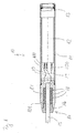
- FIG. 2 shows the measuring transducer according to the invention.
- the sensor has a tubular sensor housing 8 on with an arranged therein, electronic transmitter 11, wherein this electronic transmitter 11 at the in the figure 2 right side of a socket housing 9 and a pin tray 10 to a connection cable 1 in still can be connected to an explanatory manner.
- the electronic Transmitter 11 points to the opposite side a sensor element 12, which in a cylindrical Housing part 13 is seated.
- This cylindrical housing part 13th is O-ring seals 6 on the one hand with the sensor housing. 8 sealingly connected and the other with the pressure sensor 12th
- the housing part 13 and the sensor housing part 8 can, for example be screwed together. Other mounting options are also possible.
- connection cable 1 is on stripped of its front end so that an inner conductor the mentioned socket housing 9 is connected.
- This socket housing 9 is intended for a suitable plug connection of the electrical transmitter 11 attached to become.
- connection cable 1 has at its front, free end via an internal ventilation cable 1a. This ventilation cable 1a is optional and does not have to be provided.
- a cable receptacle 2 To the connection cable 1 around sits a cable receptacle 2, the is preferably formed of plastic material. For reasons of elasticity is in this cable receptacle 2 an annular and incorporated concentric opening to the axis of the cable 1, in which preferably a metallic support ring sits.
- the Cable holder 2 also has a centric, conical widening opening, within which a correspondingly conical extending support sleeve 3 is seated.
- the cable 1 is like this prepared that the cable sheath 1b in the mounted state between the wall of the cable receptacle 2 and the outer wall the conically extending support sleeve 3 is clamped.
- a compression spring element 4 here as a cylindrical, elastic Part is executed, arranged.
- a spring housing 5 To this compression spring element 4th around is a spring housing 5.
- This spring housing 5 closes flush with the above-mentioned annular sleeve 15 at.
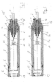
- the spring housing 5 also integral with the annular sleeve 15th be made.
- the spring housing 5 engages on his in Figure 2 and Figure 3 left edge shown around the compression spring element 4 around and sits down sleeve-shaped with a reduced Diameter to the socket housing 9 away.
- the spring housing 5 moreover, one half of its extension follows one outside leaping, encircling hexagon 5a at the same time a stop for the cable housing 2 and as a month mate serves.
- the cable receiving housing 2 has a circumferential, annular groove in which sits another O-ring.
- thermoplastic housing As with conventional cable seals is the case, be avoided can.
- connection cable 1 which was previously installed in another transducer, not crushed. This will prevent the ingress of media, such as z. As liquids, effectively prevented in the probe.
- the temperature of the medium can reach the temperature limit the electronics can and are operated Media measured with the transducer according to the invention are, despite the swelling effect of the plastic does not lead to failure lead the probe.
- the probe can after of the invention are operated in media in which elastomers the cable seal are not resistant, since molded seals made of high quality elastomeric materials, such as Kalrez not Available from stock and therefore in relation to the device price are not marketable.
Abstract
Description
Die Erfindung betrifft einen Messwertaufnehmer, insbesondere einen Füllstandssensor, Druckmessumformer oder dergleichen, mit einem einen Sensor aufnehmenden Gehäuse und einer aus dem Gehäuse lösbaren und in das Gehäuse einbringbaren Kabeldurchführung, wobei die Kabeldurchführung mindestens eine Formdichtung aufweist.The invention relates to a transducer, in particular a level sensor, pressure transmitter or the like, with a sensor receiving housing and one of the Housing detachable and can be introduced into the housing grommet, wherein the cable gland at least one molded seal having.
Fig. 1 zeigt einen aus dem Stand der Technik bekannten Messwertaufnehmer
10 mit einem Gehäuse 11, in dem ein elektronischer
Messumformer 12 und ein Sensor 13 untergebracht sind.
Ferner weist der Messwertaufnehmer 10 eine Kabeldurchführung
14 zur Durchführung eines Kabels 15 auf. Die Kabeldurchführung
14 kann eine Elastomer-Formdichtung 17 oder mehrere Elastomer-Formdichtugne
18 aufweisen, die durch eine Druckschraube 16
komprimiert werden. Aus dem Kabel 15 kommen Adern 19, die mittels
Steckelementen 100, die als Stoßverbinder, Flachstecker
oder Aderendhülsen ausgebildet sein können, an den elektronischen
Messumformer 12 eingesteckt sind. Zur Verbesserung der
Dichtheit werden die Elastomer-Formdichtungen 17 und 18 häufig
mit dem Kabel 15 und einer Kabelaufnahme 101 verklebt. Bei der
Demontage, die beispielsweise durch einen Servicevorgang bedingt
sein kann, werden die verklebten Elastomer-Formdichtungen
17 und 18 zwangsweise beschädigt, so dass sie nicht mehr zu
verwenden sind und gegen neue ausgetauscht werden müssen. Wenn
auf eine Verklebung zwischen dem Kabel 15 und den Elastomer-Dichtungen
17 und 18 und der Kabelaufnahme 101 verzichtet
wird, können die Elastomer-Formdichten 17 und 18 im Laufe der
Zeit sowohl an dem Kabel 15 wie auch an der Kabelaufnahme 101
so stark festhaften, dass die Elastomer-Dichtungen 17 und 18
bei der Demontage der Kabeldurchführung 14 ebenfalls unvermeidbar
zerstört werden. Um die Zerstörung der Elastomer-Dichtungen
17 und 18 bei der Demontage der Kabeldurchführung
14 zu vermeiden, werden häufig Mittel zur Reduzierung der Reibung
verwendet, die jedoch im Laufe der Zeit durch die den
Messwertaufnehmer 10 umgebenden Medien ausgewaschen werden
oder sich bei hohen Temperaturen zersetzen oder verflüchtigen.
Deshalb ist eine Demontage der Kabeldurchführung 14 ohne eine
Zerstörung der Elastomer-Formdichtungen 17 und 18 nach dem
Stand der Technik nicht möglich. Bei der Demontage der Kabeldurchführung
14 werden zwangsläufig auch die Steckelemente 100
von dem elektronischen Messumformer 12 entfernt. Beim Lösen
der Steckelemente 100 bei anliegender Versorgungsspannung kann
beispielsweise infolge einer Drehbewegung der Kabeldurchführung
14 ein unerwünschter Kurzschluss im Stromkreis entsehen.Fig. 1 shows a known from the
Die Erfindung hat die Aufgabe, einen Messwertaufnehmer der eingangs genannten Art dahingehend zu verbessern, dass zukünftig die Formdichtung bei der Demontage oder Montage nicht beschädigt wird.The invention has the task of a transducer of to improve the type mentioned above in the future the molded gasket is not damaged during disassembly or assembly becomes.
Die Erfindung löst die gestellte Aufgabe durch einen Messwertaufnehmer der eingangs genannten Art, der erfindungsgemäß dadurch gekennzeichnet ist, dass die mindestens eine Formdichtung von einem Kabeldurchführungsgehäuse umgeben ist. Somit kann die mindestens eine Formdichtung nicht beim Demontieren oder Montieren der Kabeldurchführung an dem Gehäuse des Messwertaufnehmers festhaften oder reiben, so dass eine Beschädigung der mindestens einen Formdichtung zuverlässig ausgeschlossen ist und die Abdichtung zwischen dem Kabel und der mindestens einen Formdichtung unverändert erhalten bleibt. Somit kann beispielsweise im Servicefall ein mit der Kabeldurchführung verbundener elektrische Anschluss schnell und problemlos auf einen anderen Messwertaufnehmer umgesteckt werden. The invention solves the task by a transducer of the aforementioned type, the invention thereby is characterized in that the at least one molded seal surrounded by a cable feedthrough housing. Consequently The at least one molded gasket can not be disassembled or mounting the cable gland on the housing of the sensor stick or rub, causing damage the reliably excluded at least one molded seal is and the seal between the cable and the at least one molded seal remains unchanged. Consequently can, for example, in case of service with the cable gland connected electrical connection quickly and easily be transferred to another transducer.
Mittels einer an dem Gehäuse des Messwertaufnehmers aufschraubbaren Überwurfmutter kann das Kabeldurchführungsgehäuse mit dem Gehäuse des Messwertaufnehmers verschraubt werden. Auf diese Weise lässt sich die Kabeldurchführung mit wenigen Handgriffen schnell und zuverlässig mit dem Gehäuse des Messwertaufnehmers verbinden.By means of a screwed onto the housing of the transducer Union nut can be the cable gland housing be bolted to the housing of the sensor. On This way, the cable entry can be done in a few steps fast and reliable with the housing of the sensor connect.
Um die Dichtwirkung der mindestens einen Formdichtung zu erhöhen, kann sie mit einem Federelement, z.B. einer Druckfeder, zusammenwirken. Das Federelement komprimiert dabei die das Kabel umschließende mindestens eine Formdichtung und erhöht somit die Dichtwirkung der mindestens einen Formdichtung.In order to increase the sealing effect of the at least one molded seal, if it can be fitted with a spring element, e.g. a compression spring, interact. The spring element compresses the cable enclosing at least one molded seal and thus increases the sealing effect of the at least one molded seal.
Zur optimalen Übertragung der Federkraft auf die mindestens eine Formdichtung und um diese vor Beschädigungen durch die Druckfeder zu schützen, kann zwischen der Druckfeder und der mindestens einen Formdichtung ein Ring angeordnet sein.For optimum transfer of the spring force to the at least a molded gasket and this against damage by the To protect compression spring, can between the compression spring and the at least one mold seal to be arranged a ring.
Zwecks einer leichten und schnellen Montage kann in das Kabeldurchführungsgehäuse ein die Druckfeder aufnehmendes Federgehäuse eingeschraubt werden.For a quick and easy installation can be in the cable gland housing a compression spring receiving spring housing be screwed.
Zur leichteren Montage und Demontage der Kabeldurchführung mit dem Gehäuse oder von dem Gehäuse des Messwertaufnehmers kann in dem Kabel eine in das Innere des Gehäuses mündende Be- und Entlüftungsleitung angeordnet sein. Bei der Montage der Kabeldurchführung auf das Gehäuse kann somit durch die Entlüftungsleitung die im Gehäuseinneren befindliche Luft in die Umgebung entweichen. Bei der Demontage der Kabeldurchführung von dem Gehäuse hingegen kann durch die Belüftungsleitung Luft in das Gehäuseinnere eintreten, so dass beim Abziehen der Kabeldurchführung von dem Gehäuse kein Unterdruck im Gehäuseinneren entsteht, der ein Abziehen der Kabeldurchführung von dem Gehäuse des Messwertaufnehmers erschweren würde.For easier assembly and disassembly of the cable gland with the housing or from the housing of the transducer can in the cable opening into the interior of the housing Be and Be arranged vent line. When installing the cable gland on the housing can thus through the vent line the air inside the enclosure into the environment escape. When disassembling the cable gland from the Housing, however, can through the ventilation air in the Housing interior occur, so that when pulling off the cable gland there is no negative pressure inside the housing, the removal of the cable gland from the housing would complicate the transducer.
Am freien Ende des Federgehäuses können elektrische Steckanschlüsse angebracht sein, die starr mit der Kabeldurchführung verbunden sind und somit auch bei einer Demotage der Kabeldurchführung bei anliegender elektrischer Versorgungsspannung kurzschlusssicher aus den mit ihnen verbunden Anschlussbuchsen herausgezogen werden können.At the free end of the spring housing electrical plug connections be attached rigidly with the cable gland are connected and thus also in a demotage of the cable gland with applied electrical supply voltage Short-circuit proof from the connection sockets connected to them can be pulled out.
Um eine optimale Dichtwirkung zwischen dem Kabeldurchführungsgehäuse und dem Gehäuse des Messwertaufnehmers sicherzustellen, kann zwischen dem Kabeldurchführungsgehäuse und dem Gehäuse des Messwertaufnehmers ein O-Ring angeordnet sein.For optimum sealing effect between the cable gland housing and to ensure the housing of the sensor can be between the cable gland housing and the housing be arranged an O-ring of the transducer.
Nachfolgend wird ein Ausführungsbeispiel des erfindungsgemäßen Messwertaufnehmers anhand der beiliegenden Zeichnung näher erläutert.Hereinafter, an embodiment of the invention Sensor explained in more detail with reference to the accompanying drawings.
Im Einzelnen zeigen:
- Fig. 1
- einen Längsschnitt durch einen aus dem Stand der Technik bekannten Messwertaufnehmer;
- Fig. 2
- einen Längsschnitt durch einen ersten erfindungsgemäßen Messwertaufnehmer und
- Fig. 3
- einen Längsschnitt durch einen zweiten erfindungsgemäßen Messwertaufnehmer.
- Fig. 1
- a longitudinal section through a known from the prior art transducers;
- Fig. 2
- a longitudinal section through a first inventive transducer and
- Fig. 3
- a longitudinal section through a second inventive transducer.
In Figur 2 ist der erfindungsgemäße Messwertaufnehmer dargestellt.
Der Messwertaufnehmer weist ein rohrförmiges Sensorgehäuse
8 auf mit einem darin angeordneten, elektronischen Messumformer
11, wobei dieser elektronische Messumformer 11 an der
in der Figur 2 dargestellten rechten Seite über ein Buchsengehäuse
9 und eine Stiftwanne 10 an ein Anschlusskabel 1 in noch
zu erläuternder Weise angeschlossen werden kann. Der elektronische
Messumformer 11 weist an der gegenüberliegenden Seite
ein Sensorelement 12 auf, welches in einem zylinderförmigen
Gehäuseteil 13 sitzt. Dieses zylinderförmige Gehäuseteil 13
ist über O-Ringdichtungen 6 einerseits mit dem Sensorgehäuse 8
dichtend in Verbindung und zum anderen mit dem Drucksensor 12.
Das Gehäuseteil 13 und der Sensorgehäuseteil 8 können beispielsweise
miteinander verschraubt sein. Andere Befestigungsmöglichkeiten
sind ebenfalls denkbar.FIG. 2 shows the measuring transducer according to the invention.
The sensor has a
Der elektrische Anschluss des Kabels 1 an dem elektronischen
Messumformer 11 geschieht in besonderer Art und Weise, die
nachfolgend erläutert werden wird. Das Anschlusskabel 1 ist an
seinem vorderen Ende so abisoliert, dass ein Innenleiter an
das erwähnte Buchsengehäuse 9 angeschlossen ist. Dieses Buchsengehäuse
9 ist dazu vorgesehen, auf einen geeigneten Steckanschluss
des elektrischen Messumformers 11 aufgesteckt zu
werden. Zusätzlich verfügt das Anschlusskabel 1 an seinem vorderen,
freien Ende über eine innenliegende Belüftungskabelare
1a. Diese Belüftungskabelare 1a ist optional und muss nicht
vorgesehen sein.The electrical connection of the
Um das Anschlusskabel 1 herum sitzt eine Kabelaufnahme 2, die
vorzugsweise aus Kunststoffmaterial gebildet ist. Aus Elastizitätsgründen
ist in diese Kabelaufnahme 2 eine ringförmige
und zur Achse des Kabels 1 konzentrische Öffnung eingearbeitet,
in der vorzugsweise ein metallischer Stützring sitzt. Die
Kabelaufnahme 2 hat darüber hinaus eine zentrische, sich konisch
erweiternde Öffnung, innerhalb der eine entsprechend konisch
verlaufende Stützhülse 3 sitzt. Das Kabel 1 ist dabei so
aufbereitet, dass der Kabelmantel 1b im montierten Zustand
zwischen der Wandung der Kabelaufnahme 2 und der Außenwandung
der konisch verlaufenden Stützhülse 3 eingeklemmt ist. An die
in Figur 2 links dargestellte, vertikal zur Achse des Kabelmantels
1 verlaufenden Wandung der Stützhülse 3 ist ein Druckfederelement
4, das hier als zylinderförmiges, elastisches
Teil ausgeführt ist, angeordnet. Um dieses Druckfederelement 4
herum ist ein Federgehäuse 5. Dieses Federgehäuse 5 schließt
bündig an die oben erwähnte Ringhülse 15 an. Gemäß Figur 3
kann das Federgehäuse 5 auch einstückig mit der Ringhülse 15
gefertigt sein. Das Federgehäuse 5 greift an seinem in Figur 2
und Figur 3 links dargestellten Rand um das Druckfederelement
4 herum und setzt sich hülsenförmig mit einem verringerten
Durchmesser zum Buchsengehäuse 9 hin fort. Das Federgehäuse 5
weist darüber hinaus auf seiner halben Erstreckung einen nach
außen springenden, umlaufenden Sechskant 5a auf, der zugleich
einen Anschlag für das Kabelaufnahmegehäuse 2 und als Monatgehilfe
dient. Das Kabelaufnahmegehäuse 2 weist eine umlaufende,
ringförmige Nut auf, in der ein weiterer O-Ring sitzt.To the
Die gesamte Anordnung bestehend aus Kabelaufnahmegehäuse 2,
Ringhülse 15 mit darin befindlicher, konischer Stützhülse 3,
Druckfederelement 4 sowie Federgehäuse 5 bildet eine bauliche
Einheit, die mittels Überwurfhülse 7 an dem Sensorgehäuse 8
befestigbar ist.The entire arrangement consisting of
Der wesentliche Vorteil der erfindungsgemäßen Ausführung, wie
z. B. in den Figuren 2 und 3 gezeigt, besteht darin, dass das
Zerstören des thermoplastischen Kunststoffgehäuses, wie es bei
herkömmlichen Kabelabdichtungen der Fall ist, vermieden werden
kann. Bei Austausch des Sensors ist nämlich das Anschlusskabel
1, das zuvor in einem anderen Messwertaufnehmer eingebaut war,
nicht gequetscht. Damit wird das Eindringen von Medien, wie
z. B. Flüssigkeiten, in die Messsonde wirksam verhindert.
Durch diese Maßnahme kann die Medientemperatur bis an die Temperaturgrenze
der Elektronik betrieben werden und es können
Medien mit dem erfindungsgemäßen Messwertaufnehmer gemessen
werden, die trotz Quellwirkung des Kunststoffes nicht zum Ausfall
der Messsonde führen. Weiterhin kann die Messsonde nach
der Erfindung in Medien betrieben werden, bei denen Elastomere
der Kabelabdichtung nicht beständig sind, da Formdichtungen
aus hochwertigen Elastomerwerkstoffen, wie z.B. Kalrez nicht
ab Lager verfügbar und damit im Verhältnis zum Gerätepreis
nicht marktfähig sind.The main advantage of the embodiment according to the invention, such
z. B. shown in Figures 2 and 3, it is that the
Destroying the thermoplastic housing, as with
conventional cable seals is the case, be avoided
can. When replacing the sensor is namely the
Claims (6)
dadurch gekennzeichnet, dass neben dem Druck-Federelement (4) eine konische Stützhülse (3) angeordnet ist und ein Kabelaufnahmegehäuse (2) aus thermoplastischem Material mit einer konischen Öffnung vorgesehen ist, in welcher die konische Stützhülse (3) eingreift und wobei zwischen der konischen Stützhülse (3) und dem Kabelaufnahmegehäuse (2) ein Kabelmantel (1b) des Anschlusskabels (1) eingeklemmt ist, wobei das Druckfederelement (4) von einem Federgehäuse (5) umgeben ist und das Kabelaufnahmegehäuse (2) mittels Überwurfhülse (7) an dem Sensorgehäuse (8) festlegbar ist.Filling level sensor with a sensor (11, 12) receiving housing (8), through whose one opening a connecting cable (1) for connection to the sensor (11, 12) is provided and wherein the connecting cable (1) by a pressure-spring element ( 4) is surrounded,
characterized in that in addition to the compression spring element (4) a conical support sleeve (3) is arranged and a cable receiving housing (2) made of thermoplastic material is provided with a conical opening in which the conical support sleeve (3) engages and wherein between the conical Support sleeve (3) and the cable receiving housing (2) a cable sheath (1b) of the connecting cable (1) is clamped, wherein the compression spring element (4) by a spring housing (5) is surrounded and the cable receiving housing (2) by means of cap sleeve (7) on the Sensor housing (8) can be fixed.
dadurch gekennzeichnet, dass in dem Kabelaufnahmegehäuse (2) ein Stützring, vorzugsweise aus Metall, angeordnet ist.Transducer according to claim 1,
characterized in that in the cable receiving housing (2) a support ring, preferably made of metal, is arranged.
dadurch gekennzeichnet, dass das Federgehäuse (5) und der Stützring einstückig ausgebildet sind.Sensor according to claim 2,
characterized in that the spring housing (5) and the support ring are integrally formed.
dadurch gekennzeichnet, dass das Stützring aus einem Werkstoff besteht, der eine größere Festigkeit als das Kabelaufnahmegehäuse (2) hat. Sensor according to one of claims 1 to 3,
characterized in that the support ring is made of a material having a greater strength than the cable receiving housing (2).
dadurch gekennzeichnet, dass das Druckfederelement (4) als Spiralfeder ausgebildet ist.Transducer according to one of claims 1 to 4,
characterized in that the compression spring element (4) is designed as a spiral spring.
dadurch gekennzeichnet, dass das Druckfederelement (4) ein zylindrisches Teil aus einem elastischen Werkstoff ist.Transducer according to one of Claims 1 to 5, characterized
characterized in that the compression spring element (4) is a cylindrical part made of an elastic material.
Applications Claiming Priority (2)
| Application Number | Priority Date | Filing Date | Title |
|---|---|---|---|
| DE10357041A DE10357041A1 (en) | 2003-12-04 | 2003-12-04 | transducer |
| DE10357041 | 2003-12-04 |
Publications (3)
| Publication Number | Publication Date |
|---|---|
| EP1538427A2 true EP1538427A2 (en) | 2005-06-08 |
| EP1538427A3 EP1538427A3 (en) | 2007-02-14 |
| EP1538427B1 EP1538427B1 (en) | 2015-04-22 |
Family
ID=34442479
Family Applications (1)
| Application Number | Title | Priority Date | Filing Date |
|---|---|---|---|
| EP20040026886 Expired - Fee Related EP1538427B1 (en) | 2003-12-04 | 2004-11-12 | Compression spring element for connecting a cable to a transducer |
Country Status (4)
| Country | Link |
|---|---|
| US (1) | US7143646B2 (en) |
| EP (1) | EP1538427B1 (en) |
| CN (1) | CN100472185C (en) |
| DE (1) | DE10357041A1 (en) |
Cited By (1)
| Publication number | Priority date | Publication date | Assignee | Title |
|---|---|---|---|---|
| US7764866B2 (en) | 2004-12-10 | 2010-07-27 | Lg Electronics, Inc. | Recording medium, method for searching for content data from the recording medium, and method and apparatus for reproducing data from the recording medium |
Families Citing this family (7)
| Publication number | Priority date | Publication date | Assignee | Title |
|---|---|---|---|---|
| DK2241344T3 (en) * | 2009-04-16 | 2014-03-03 | Hoffmann La Roche | Portable infusion with feel-testing device |
| CN102044810B (en) * | 2009-10-12 | 2013-10-30 | 西安威尔罗根能源科技有限公司 | Connection device of electronic instrument framework |
| CN102680052B (en) * | 2012-05-10 | 2013-10-30 | 苏州赛智达智能科技有限公司 | Connecting structure of leading-out lead of capacitive low-temperature liquid level meter |
| EP3045880A1 (en) * | 2015-01-14 | 2016-07-20 | VEGA Grieshaber KG | Limit state measurement assembly |
| CN105333939B (en) * | 2015-11-27 | 2018-04-17 | 四川奇石缘科技股份有限公司 | The waterproof connector of I-shaped beam type dynamic weighing sensor for vehicle |
| FR3055963B1 (en) * | 2016-09-12 | 2018-08-24 | Pierre Payraud | FIXING DEVICE FOR HOLDING A SENSOR |
| CN111595301B (en) * | 2020-05-20 | 2021-11-23 | 福建省伟志地理信息科学研究院 | Aerial surveying device for geographic information system and surveying method thereof |
Citations (4)
| Publication number | Priority date | Publication date | Assignee | Title |
|---|---|---|---|---|
| DE2744864A1 (en) * | 1977-10-05 | 1979-04-19 | Endress Hauser Gmbh Co | DEVICE FOR FASTENING A PROBE IN AN OPENING OF A CONTAINER |
| DD287126A5 (en) * | 1989-08-02 | 1991-02-14 | Zft Inst Fuer Energieversorgun | DEVICE FOR THE ELECTROTECHNICAL CONNECTION OF CABLES AND CABLES TO GEFAESSES WITH HIGH PRESSURE AND TEMPERATURE DIFFERENCES |
| DE19728370A1 (en) * | 1997-07-03 | 1999-01-07 | Bosch Gmbh Robert | Cable bushing sealing device for at least one connecting cable esp. of gas sensor |
| WO2002063735A1 (en) * | 2001-02-06 | 2002-08-15 | Endress+Hauser Gmbh + Co. Kg. | Cable duct |
Family Cites Families (15)
| Publication number | Priority date | Publication date | Assignee | Title |
|---|---|---|---|---|
| US2460304A (en) * | 1944-07-29 | 1949-02-01 | Mcgee Kenneth | Connector |
| US3264602A (en) * | 1964-03-13 | 1966-08-02 | Automatic Metal Products Corp | Electrical connectors for coaxial cables |
| US3403671A (en) * | 1965-10-24 | 1968-10-01 | Magnaflux Corp | Ultrasonic transducer system |
| DE3215040C2 (en) * | 1982-04-22 | 1985-11-07 | VEGA Grieshaber -GmbH & Co, 7622 Schiltach | Resonance rod |
| GB8601278D0 (en) * | 1986-01-20 | 1986-02-26 | British Telecomm | Clamp assembly |
| JPH0341434Y2 (en) * | 1986-09-17 | 1991-08-30 | ||
| JPH03148028A (en) * | 1989-11-02 | 1991-06-24 | Matsushita Electric Ind Co Ltd | Piezoelectric pressure sensor |
| NL9000802A (en) * | 1990-04-05 | 1991-11-01 | Texas Instruments Holland | SENSOR FOR MEASURING THE PRESSURE OF A MEDIUM, IN PARTICULAR FOR MEASURING THE VARYING PRESSURE IN A DIESEL INJECTION PUMP. |
| DE19542650A1 (en) * | 1995-11-15 | 1997-05-22 | Bosch Gmbh Robert | Temperature-resistant cable entry and method for its production |
| US6113429A (en) * | 1997-02-25 | 2000-09-05 | Dbt Automation Gmbh | Plug-type coupling for sheathed electrical cables |
| EP1083414A1 (en) * | 1999-09-11 | 2001-03-14 | Endress + Hauser GmbH + Co. | Level measuring device |
| WO2001040740A1 (en) * | 1999-11-30 | 2001-06-07 | Nippon Seiki Co.,Ltd | Liquid level detector |
| DE50015477D1 (en) * | 2000-02-15 | 2009-01-22 | Endress & Hauser Gmbh & Co Kg | pressure sensor |
| DE10212903B4 (en) * | 2002-03-22 | 2007-02-01 | Vega Grieshaber Kg | transducer |
| DE10331967A1 (en) * | 2003-07-15 | 2005-02-03 | Robert Bosch Gmbh | sensor device |
-
2003
- 2003-12-04 DE DE10357041A patent/DE10357041A1/en not_active Withdrawn
-
2004
- 2004-11-12 EP EP20040026886 patent/EP1538427B1/en not_active Expired - Fee Related
- 2004-12-02 US US11/001,567 patent/US7143646B2/en active Active
- 2004-12-03 CN CNB2004100983396A patent/CN100472185C/en not_active Expired - Fee Related
Patent Citations (4)
| Publication number | Priority date | Publication date | Assignee | Title |
|---|---|---|---|---|
| DE2744864A1 (en) * | 1977-10-05 | 1979-04-19 | Endress Hauser Gmbh Co | DEVICE FOR FASTENING A PROBE IN AN OPENING OF A CONTAINER |
| DD287126A5 (en) * | 1989-08-02 | 1991-02-14 | Zft Inst Fuer Energieversorgun | DEVICE FOR THE ELECTROTECHNICAL CONNECTION OF CABLES AND CABLES TO GEFAESSES WITH HIGH PRESSURE AND TEMPERATURE DIFFERENCES |
| DE19728370A1 (en) * | 1997-07-03 | 1999-01-07 | Bosch Gmbh Robert | Cable bushing sealing device for at least one connecting cable esp. of gas sensor |
| WO2002063735A1 (en) * | 2001-02-06 | 2002-08-15 | Endress+Hauser Gmbh + Co. Kg. | Cable duct |
Cited By (1)
| Publication number | Priority date | Publication date | Assignee | Title |
|---|---|---|---|---|
| US7764866B2 (en) | 2004-12-10 | 2010-07-27 | Lg Electronics, Inc. | Recording medium, method for searching for content data from the recording medium, and method and apparatus for reproducing data from the recording medium |
Also Published As
| Publication number | Publication date |
|---|---|
| EP1538427A3 (en) | 2007-02-14 |
| EP1538427B1 (en) | 2015-04-22 |
| DE10357041A1 (en) | 2005-07-07 |
| US20060037391A1 (en) | 2006-02-23 |
| US7143646B2 (en) | 2006-12-05 |
| CN100472185C (en) | 2009-03-25 |
| CN1624434A (en) | 2005-06-08 |
Similar Documents
| Publication | Publication Date | Title |
|---|---|---|
| EP2382693B1 (en) | Fixing device for fixing a cable at a housing feed-through | |
| EP3590162B1 (en) | Holding device for holding a shielded cable | |
| EP1942325B1 (en) | Sealing device for sealing a pressure gauge cell unit, pressure gauge cell unit respectively measuring device fitted therewith | |
| EP2652840B1 (en) | Cable gland | |
| CH665279A5 (en) | CAPACITIVE SENSOR. | |
| EP2609657A1 (en) | Cable strain relief | |
| DE202017101060U1 (en) | Connector, in particular for high-current application | |
| EP1538427B1 (en) | Compression spring element for connecting a cable to a transducer | |
| DE102006062609A1 (en) | Cable feedthrough and/or insertion component for mechanical sealing and/or clamping and electrical shielding and/or conducting in e.g. breathable or non-breathable cable, has sections sealing and/or clamping, conducting and shielding cable | |
| DE102017209368A1 (en) | Cable gland with shielding and sealing properties | |
| EP1657795B1 (en) | Cable plug of a plug-type connection device for medium-voltage and high-voltage technics | |
| EP0638976A1 (en) | Sleeve end for a cable sleeve with a sealing insert of resilient material | |
| DE202014102317U1 (en) | Sleeve for connecting cable and shaft tube with multiple protection against air, water and traction | |
| DE202006001904U1 (en) | Modular protective housing e.g. for process engineering, has first and second potential rails coupled to form common potential rail | |
| EP2184822B1 (en) | Submersible motor | |
| EP0908995B1 (en) | Cable gland for shielded cable | |
| DE10235212A1 (en) | Electrical sleeve connector for connecting electrical equipment to a power source has an external casing with a tubular extension for a through-cable and watertight elastomer seals to fix a connector on a plug-in connection block. | |
| DE102008055841A1 (en) | Electrical plug connector part for use in gear case of motor vehicle, has housing part and housing body forming flange to form-fittingly enclose electrical lines in final locked position | |
| DE69723720T2 (en) | HIGH VOLTAGE ARRANGEMENT WITH DETACHABLE ELEMENTS | |
| EP1585945A2 (en) | Fixing system for a measuring device for monitoring and/or determination of a filling level | |
| DE19751786A1 (en) | Round plug connector for screened electrical cable | |
| DE102014103436A1 (en) | Electrical connector, electrical connection, as well as electrical device or aggregate | |
| EP3807959B1 (en) | Device for connecting high-voltage conductors | |
| EP1303020B1 (en) | Electrical cabling with strain relief means | |
| DE4403571C1 (en) | Coupling for plastic insulated high voltage cables has screw terminal block within housing that has inner and outer sections of that shrouds connection. |
Legal Events
| Date | Code | Title | Description |
|---|---|---|---|
| PUAI | Public reference made under article 153(3) epc to a published international application that has entered the european phase |
Free format text: ORIGINAL CODE: 0009012 |
|
| AK | Designated contracting states |
Kind code of ref document: A2 Designated state(s): AT BE BG CH CY CZ DE DK EE ES FI FR GB GR HU IE IS IT LI LU MC NL PL PT RO SE SI SK TR |
|
| AX | Request for extension of the european patent |
Extension state: AL HR LT LV MK YU |
|
| PUAL | Search report despatched |
Free format text: ORIGINAL CODE: 0009013 |
|
| AK | Designated contracting states |
Kind code of ref document: A3 Designated state(s): AT BE BG CH CY CZ DE DK EE ES FI FR GB GR HU IE IS IT LI LU MC NL PL PT RO SE SI SK TR |
|
| AX | Request for extension of the european patent |
Extension state: AL HR LT LV MK YU |
|
| RIC1 | Information provided on ipc code assigned before grant |
Ipc: G01F 23/00 20060101AFI20050405BHEP Ipc: H01R 13/52 20060101ALI20070110BHEP Ipc: G01D 11/24 20060101ALI20070110BHEP |
|
| 17P | Request for examination filed |
Effective date: 20070330 |
|
| AKX | Designation fees paid |
Designated state(s): DE FR GB |
|
| 17Q | First examination report despatched |
Effective date: 20091123 |
|
| GRAP | Despatch of communication of intention to grant a patent |
Free format text: ORIGINAL CODE: EPIDOSNIGR1 |
|
| INTG | Intention to grant announced |
Effective date: 20141120 |
|
| GRAP | Despatch of communication of intention to grant a patent |
Free format text: ORIGINAL CODE: EPIDOSNIGR1 |
|
| INTG | Intention to grant announced |
Effective date: 20150108 |
|
| GRAS | Grant fee paid |
Free format text: ORIGINAL CODE: EPIDOSNIGR3 |
|
| GRAA | (expected) grant |
Free format text: ORIGINAL CODE: 0009210 |
|
| AK | Designated contracting states |
Kind code of ref document: B1 Designated state(s): DE FR GB |
|
| REG | Reference to a national code |
Ref country code: GB Ref legal event code: FG4D Free format text: NOT ENGLISH |
|
| REG | Reference to a national code |
Ref country code: DE Ref legal event code: R096 Ref document number: 502004014888 Country of ref document: DE Effective date: 20150528 |
|
| REG | Reference to a national code |
Ref country code: FR Ref legal event code: PLFP Year of fee payment: 12 |
|
| REG | Reference to a national code |
Ref country code: DE Ref legal event code: R097 Ref document number: 502004014888 Country of ref document: DE |
|
| PLBE | No opposition filed within time limit |
Free format text: ORIGINAL CODE: 0009261 |
|
| STAA | Information on the status of an ep patent application or granted ep patent |
Free format text: STATUS: NO OPPOSITION FILED WITHIN TIME LIMIT |
|
| 26N | No opposition filed |
Effective date: 20160125 |
|
| REG | Reference to a national code |
Ref country code: FR Ref legal event code: PLFP Year of fee payment: 13 |
|
| REG | Reference to a national code |
Ref country code: FR Ref legal event code: PLFP Year of fee payment: 14 |
|
| PGFP | Annual fee paid to national office [announced via postgrant information from national office to epo] |
Ref country code: FR Payment date: 20191121 Year of fee payment: 16 |
|
| PGFP | Annual fee paid to national office [announced via postgrant information from national office to epo] |
Ref country code: GB Payment date: 20191126 Year of fee payment: 16 |
|
| PGFP | Annual fee paid to national office [announced via postgrant information from national office to epo] |
Ref country code: DE Payment date: 20201125 Year of fee payment: 17 |
|
| GBPC | Gb: european patent ceased through non-payment of renewal fee |
Effective date: 20201112 |
|
| PG25 | Lapsed in a contracting state [announced via postgrant information from national office to epo] |
Ref country code: FR Free format text: LAPSE BECAUSE OF NON-PAYMENT OF DUE FEES Effective date: 20201130 |
|
| PG25 | Lapsed in a contracting state [announced via postgrant information from national office to epo] |
Ref country code: GB Free format text: LAPSE BECAUSE OF NON-PAYMENT OF DUE FEES Effective date: 20201112 |
|
| REG | Reference to a national code |
Ref country code: DE Ref legal event code: R119 Ref document number: 502004014888 Country of ref document: DE |
|
| PG25 | Lapsed in a contracting state [announced via postgrant information from national office to epo] |
Ref country code: DE Free format text: LAPSE BECAUSE OF NON-PAYMENT OF DUE FEES Effective date: 20220601 |