EP1538303A1 - Einrichtung zum Auspressen von Mörtel oder Klebstoffen in Bohrlöchern für Gebirgsanker - Google Patents
Einrichtung zum Auspressen von Mörtel oder Klebstoffen in Bohrlöchern für Gebirgsanker Download PDFInfo
- Publication number
- EP1538303A1 EP1538303A1 EP04450222A EP04450222A EP1538303A1 EP 1538303 A1 EP1538303 A1 EP 1538303A1 EP 04450222 A EP04450222 A EP 04450222A EP 04450222 A EP04450222 A EP 04450222A EP 1538303 A1 EP1538303 A1 EP 1538303A1
- Authority
- EP
- European Patent Office
- Prior art keywords
- pressure member
- flexible pressure
- chamber
- borehole
- adhesives
- Prior art date
- Legal status (The legal status is an assumption and is not a legal conclusion. Google has not performed a legal analysis and makes no representation as to the accuracy of the status listed.)
- Granted
Links
- 239000000853 adhesive Substances 0.000 title claims abstract description 17
- 230000001070 adhesive effect Effects 0.000 title claims abstract description 17
- 239000011435 rock Substances 0.000 title claims abstract description 7
- 239000004570 mortar (masonry) Substances 0.000 title claims abstract description 4
- 238000004873 anchoring Methods 0.000 abstract 1
- 238000005553 drilling Methods 0.000 description 6
- 230000004323 axial length Effects 0.000 description 2
- 230000004913 activation Effects 0.000 description 1
- 230000008878 coupling Effects 0.000 description 1
- 238000010168 coupling process Methods 0.000 description 1
- 238000005859 coupling reaction Methods 0.000 description 1
- 238000001125 extrusion Methods 0.000 description 1
- 210000003746 feather Anatomy 0.000 description 1
- 239000003292 glue Substances 0.000 description 1
- 238000012986 modification Methods 0.000 description 1
- 230000004048 modification Effects 0.000 description 1
- 238000009420 retrofitting Methods 0.000 description 1
- 238000007789 sealing Methods 0.000 description 1
Images


Classifications
-
- E—FIXED CONSTRUCTIONS
- E21—EARTH OR ROCK DRILLING; MINING
- E21D—SHAFTS; TUNNELS; GALLERIES; LARGE UNDERGROUND CHAMBERS
- E21D20/00—Setting anchoring-bolts
- E21D20/02—Setting anchoring-bolts with provisions for grouting
- E21D20/028—Devices or accesories for injecting a grouting liquid in a bore-hole
Definitions
- the invention relates to a device for pressing of mortar or adhesives in boreholes for rock anchors.
- self-drilling adhesive anchors are known which also be referred to as a pipe anchor.
- Such training as described, for example, in DE 100 17 750 A1, DE 100 17 751 A1 and DE 100 17 763 A1
- Adhesive cartridges being displaceable by an axially displaceable Piston adhesive can be pressed out.
- special ejection devices are used, which are connected via an adapter to the drill motor can.
- Another self-drilling glue is in the US 4,055,051 A.
- the invention now aims to provide a device of the initially mentioned type, with which adhesive in a simple Can be squeezed out without causing any manipulation are required on the drill carriage.
- the invention is aimed at the pressing of adhesive in the immediate Following the driving in of the self-drilling adhesive anchor to be able to make automatically.
- the device according to the invention substantially in that the press drive is formed by a flexible pressure member is, which from one of the axial direction of the borehole different storage location in one with the axial direction the borehole aligned operating position is displaceable.
- a flexible pressure member used for the press drive is, such a pressure member of one of the Axial direction deviated direction unwound or unwound be and be brought into an operating position in which the adhesive cartridges are pressed out accordingly.
- This operating position corresponds to the axial direction of the borehole, yes the adhesive in the axial direction from the cavity of the tubular Anchor to be pressed into the holes.
- the Training in this case made so that the flexible pressure member from a coaxial chamber to the borehole from one in the circumferential direction extending memory location in an axial operating position is displaceable.
- a coaxial to the well chamber or drum can easily in the drilling axis of the Drill mount can be swiveled and guided axially movable.
- There a circumferentially extending memory location to less axial length storing a relatively long flexible Pressure member allows, but can such a chamber, which is preferably designed as a cylindrical drum, even in one Schwenklage remain, in which the drum axis with the Axis of the borehole is aligned.
- the drum can in this case accordingly adapted drilling device behind the drill drive be arranged, wherein the pressure member through the hollow drive shaft of the drill drive can extend.
- the drum between the drill drive and the rock anchor which can be driven in the axial direction to arrange, with modifications of the drill drive are not required and a simple retrofitting existing Facilities becomes possible.
- the flexible pressure member is on a reel wound, in a simple way, the flexible Pressure member of a plurality of hingedly interconnected can be formed rod-shaped segments.
- Essential is a correspondingly high pressure resistance, with a lateral Dodging of the flexible pressure member from the axial Direction inside the tubular rock anchor anyway not possible.
- Drum is arranged additionally.
- the training is here Advantageously made such that the flexible pressure member receiving Chamber in a coaxial with the axis of the drill drive Position is pivotable, being in a particularly advantageous manner in Inside the chamber or cylindrical drum one end of the flexible pressure member is fixed.
- the education is in this case made with an advantage so that the flexible pressure member at its end remote from the extendable end at one with the rotary drive, in particular drill drive, detachable or coupled Component is set.
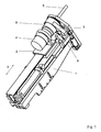
- FIG. 1 show a Drill carriage with pivoted-out pressing, Fig.2 a enlarged side view of the storage drum, Figure 3 a View of the swing arm for the drum and Fig.4 the storage drum in axial section.
- Fig.1 denotes a support arm of a drill carriage, on which on a carriage 2 in accordance with an axial direction arranged the double arrow 3 displaceable drill drive 4 is, over which a schematically indicated with 5 Rod or a rock anchor are driven into a borehole can.
- a pivot bearing 6 and a Swing arm 7 is provided, over which (n) a drum-shaped Housing 8 for the pressure member in one with the axis of the drill drive 4 aligned position can be pivoted.
- this drum-shaped housing 8 is shown enlarged, wherein the pivot axis of the pivot bearing 6 is denoted by 9 is.
- the drill drive 4 engages the stub shaft 10, wherein from the interior of the housing 8 a wound in the circumferential direction flexible pressure member 11 deflected in the direction of the axis 12 and can be squeezed.
- the receiving device for the flexible pressure member 11 This flexible pressure member consists of several segments and is wound in the circumferential direction inside the housing 8.
- the housing 8 consists of a first stationary component 13, which is connected to the pivot arm 7 is.
- This stationary component 13 comprises at its front end a corresponding sealing element 14, which in the drilling or adhesive anchor is introduced.
- On the inside includes wound guide tube 15, through which the flexible pressure member 11 is transferred to the storage threads.
- the established one Housing part 13 is in this case drum-like on the inside trained and carries on the outside of a corresponding Thread 16, on which an axially movable and by the rotating second housing part 17 driven, essentially cylindrical member 18 is guided.
- This cylindrical component 18 is formed as a sleeve and by means of a feather key 19th connected to the rotating second housing part 17.
- the flexible pressure member 11 is connected at its rear end to the rotatable sleeve 16 is fixed.
- the flexible pressure member or the flexible shaft has at its front end an adapter which opens into the packer 14.
- the drive motor drives here only the second rotatable housing part 17 via a frictional Coupling piece 21, so that the flexible pressure member 11 ejected in the axial direction or in direction of rotation reversal is wound up again.
- the ejected in the axial direction free ends of the flexible pressure member cause the mechanical feed of an extrusion piston, so that one in one Adhesive cartridge contained adhesive first mixed and in the Series can be squeezed out.
Landscapes
- Engineering & Computer Science (AREA)
- Mining & Mineral Resources (AREA)
- Geology (AREA)
- Life Sciences & Earth Sciences (AREA)
- General Life Sciences & Earth Sciences (AREA)
- Geochemistry & Mineralogy (AREA)
- Structural Engineering (AREA)
- Dowels (AREA)
- Piles And Underground Anchors (AREA)
- Earth Drilling (AREA)
- Joining Of Building Structures In Genera (AREA)
- Coating Apparatus (AREA)
- Processing Of Stones Or Stones Resemblance Materials (AREA)
Abstract
Description
Claims (7)
- Einrichtung zum Auspressen von Mörtel oder Klebstoffen in Bohrlöcher für Gebirgsanker, dadurch gekennzeichnet, dass der Pressantrieb von einem flexiblen Druckglied (11) gebildet ist, welches aus einer von der Achsrichtung des Bohrloches verschiedenen Speicherlage in eine mit der Achsrichtung des Bohrloches fluchtende Betätigungslage verschiebbar ist.
- Einrichtung nach Anspruch 1, dadurch gekennzeichnet, dass das flexible Druckglied (11) aus einer zum Bohrloch koaxialen Kammer (18) aus einer in Umfangsrichtung verlaufenden Speicherlage in eine axiale Betätigungslage verschiebbar ist.
- Einrichtung nach Anspruch 1 oder 2, dadurch gekennzeichnet, dass die Kammer (18) als zylindrische Trommel ausgebildet ist.
- Einrichtung nach Anspruch 1, 2 oder 3, dadurch gekennzeichnet, dass das flexible Druckglied (11) auf einer Haspel (13) aufgewickelt ist.
- Einrichtung nach einem der Ansprüche 1 bis 4, dadurch gekennzeichnet, dass das flexible Druckglied (11) von einer Mehrzahl von gelenkig miteinander verbundenen stabförmigen Segmenten gebildet ist.
- Einrichtung nach einem der Ansprüche 1 bis 5, dadurch gekennzeichnet, dass die das flexible Druckglied (11) aufnehmende Kammer (8) in eine mit der Achse des Bohrantriebs koaxiale Lage schwenkbar ist.
- Einrichtung nach einem der Ansprüche 1 bis 6, dadurch gekennzeichnet, dass das flexible Druckglied (11) an seinem dem ausfahrbaren Ende abgewandten Ende an einem mit dem Drehantrieb, insbesondere Bohrantrieb (4), kuppelbaren oder gekuppelten Bauteil (16) festgelegt ist.
Applications Claiming Priority (2)
| Application Number | Priority Date | Filing Date | Title |
|---|---|---|---|
| AT19462003 | 2003-12-04 | ||
| AT0194603A AT413852B (de) | 2003-12-04 | 2003-12-04 | Einrichtung zum auspressen von mörtel oder klebstoffen in bohrlöcher für gebirgsanker |
Publications (2)
| Publication Number | Publication Date |
|---|---|
| EP1538303A1 true EP1538303A1 (de) | 2005-06-08 |
| EP1538303B1 EP1538303B1 (de) | 2008-01-09 |
Family
ID=34437853
Family Applications (1)
| Application Number | Title | Priority Date | Filing Date |
|---|---|---|---|
| EP04450222A Expired - Lifetime EP1538303B1 (de) | 2003-12-04 | 2004-11-26 | Einrichtung zum Auspressen von Mörtel oder Klebstoffen in Bohrlöchern für Gebirgsanker |
Country Status (3)
| Country | Link |
|---|---|
| EP (1) | EP1538303B1 (de) |
| AT (2) | AT413852B (de) |
| DE (1) | DE502004005894D1 (de) |
Cited By (2)
| Publication number | Priority date | Publication date | Assignee | Title |
|---|---|---|---|---|
| WO2010050870A1 (en) * | 2008-10-29 | 2010-05-06 | Atlas Copco Rock Drills Ab | Injecting device, drill rig and method of rock bolting |
| CN114320355A (zh) * | 2021-11-25 | 2022-04-12 | 中国煤炭科工集团太原研究院有限公司 | 锚护喷浆机器人 |
Citations (2)
| Publication number | Priority date | Publication date | Assignee | Title |
|---|---|---|---|---|
| US4708532A (en) * | 1985-11-07 | 1987-11-24 | Oy Tampella Ab | Apparatus for storing a concrete feeding hose in a rock bolting device |
| WO1999001641A1 (en) * | 1997-07-04 | 1999-01-14 | Industrial Roll Formers Pty. Limited | An apparatus for positioning a resin cartridge |
Family Cites Families (4)
| Publication number | Priority date | Publication date | Assignee | Title |
|---|---|---|---|---|
| FI79598C (fi) * | 1985-11-07 | 1990-01-10 | Tampella Oy Ab | Foerfarande och anordning foer styrning av en betongmatningsslang vid gjutbultning i berg. |
| AUPP955399A0 (en) * | 1999-03-31 | 1999-04-29 | Hydramatic Engineering Pty. Ltd. | Method and apparatus for insertion of rockbolts |
| DE10017751B4 (de) * | 2000-04-10 | 2008-11-20 | Hilti Aktiengesellschaft | Gebirgsanker |
| DE10017763B4 (de) * | 2000-04-10 | 2008-11-20 | Hilti Aktiengesellschaft | Gebirgsanker |
-
2003
- 2003-12-04 AT AT0194603A patent/AT413852B/de not_active IP Right Cessation
-
2004
- 2004-11-26 DE DE502004005894T patent/DE502004005894D1/de not_active Expired - Lifetime
- 2004-11-26 EP EP04450222A patent/EP1538303B1/de not_active Expired - Lifetime
- 2004-11-26 AT AT04450222T patent/ATE383498T1/de active
Patent Citations (2)
| Publication number | Priority date | Publication date | Assignee | Title |
|---|---|---|---|---|
| US4708532A (en) * | 1985-11-07 | 1987-11-24 | Oy Tampella Ab | Apparatus for storing a concrete feeding hose in a rock bolting device |
| WO1999001641A1 (en) * | 1997-07-04 | 1999-01-14 | Industrial Roll Formers Pty. Limited | An apparatus for positioning a resin cartridge |
Cited By (6)
| Publication number | Priority date | Publication date | Assignee | Title |
|---|---|---|---|---|
| WO2010050870A1 (en) * | 2008-10-29 | 2010-05-06 | Atlas Copco Rock Drills Ab | Injecting device, drill rig and method of rock bolting |
| CN102197192A (zh) * | 2008-10-29 | 2011-09-21 | 阿特拉斯·科普柯凿岩设备有限公司 | 注入设备、钻车和岩石锚固方法 |
| US9157321B2 (en) | 2008-10-29 | 2015-10-13 | Atlas Copco Rock Drills Ab | Injecting device, drill rig and method of rock bolting |
| CN102197192B (zh) * | 2008-10-29 | 2015-11-25 | 阿特拉斯·科普柯凿岩设备有限公司 | 注入设备、钻车和岩石锚固方法 |
| CN114320355A (zh) * | 2021-11-25 | 2022-04-12 | 中国煤炭科工集团太原研究院有限公司 | 锚护喷浆机器人 |
| CN114320355B (zh) * | 2021-11-25 | 2023-09-19 | 中国煤炭科工集团太原研究院有限公司 | 锚护喷浆机器人 |
Also Published As
| Publication number | Publication date |
|---|---|
| ATA19462003A (de) | 2005-10-15 |
| DE502004005894D1 (de) | 2008-02-21 |
| EP1538303B1 (de) | 2008-01-09 |
| ATE383498T1 (de) | 2008-01-15 |
| AT413852B (de) | 2006-06-15 |
Similar Documents
| Publication | Publication Date | Title |
|---|---|---|
| DE3322427C2 (de) | Bohreinrichtung, insbesondere zur Verwendung im untertägigen Grubenbetrieb | |
| DE202007001858U1 (de) | Antriebsanordnung für ein Doppelbohrgestänge | |
| EP0388627A1 (de) | Rammbohrgerät | |
| DE10005475A1 (de) | Bohrvorrichtung | |
| DE1203199B (de) | Bohrgeraet | |
| AT413852B (de) | Einrichtung zum auspressen von mörtel oder klebstoffen in bohrlöcher für gebirgsanker | |
| EP0510416B1 (de) | Schlagwerk für ein Bohrgestänge | |
| DE102005000158A1 (de) | Bohr- und Ankersetzgerät mit integrierter Auspressvorrichtung | |
| DE3612762C2 (de) | Teleskopierbares Bohrgerät | |
| DE19704263C1 (de) | Bohrvorrichtung | |
| WO2013127408A1 (de) | Einrichtung zum bohren und ankersetzen | |
| DE3917603A1 (de) | Bohrvorrichtung fuer hinterschnitt | |
| DE2657751C2 (de) | Überlagerungsbohrgestänge | |
| DE1188014B (de) | Gesteinsbohrgeraet mit exzentrisch arbeitendem Bohrwerkzeug | |
| DE3024102A1 (de) | Exzenter-bohrvorrichtung | |
| DE4402487A1 (de) | Kompaktbohreinheit für gegenläufiges Überlagerungsbohren auf Kleinbohrgeräten | |
| DE2810852C2 (de) | Vorrichtung zum selbsttätigen öffnen und Schließen von Werkstoffstangen-Zuführungsrohren an Mehrspindel-Stangendrehautomaten | |
| DE102005046495B4 (de) | Bohrvorrichtung zur Erstellung verrohrter Bohrlöcher | |
| DE3336314C1 (de) | Bohrlafette | |
| DE2824722A1 (de) | Drehschlag-bohrvorrichtung | |
| DE3331502A1 (de) | Vorrichtung zum ausziehen der schnecke aus einer auspress- oder homogenisierschneckenpresse | |
| DE102012000983A1 (de) | Vorrichtung für ein Drainage-Bohr-System | |
| DE3635815A1 (de) | Anordnung zur aufbewahrung eines betonzufuehrungsschlauchs in einer felsankerungsausruestung | |
| DE102008040510A1 (de) | Setzverfahren eines selbstbohrenden, chemisch verankerbaren Befestigungselementes | |
| DE3908646C2 (de) |
Legal Events
| Date | Code | Title | Description |
|---|---|---|---|
| PUAI | Public reference made under article 153(3) epc to a published international application that has entered the european phase |
Free format text: ORIGINAL CODE: 0009012 |
|
| AK | Designated contracting states |
Kind code of ref document: A1 Designated state(s): AT BE BG CH CY CZ DE DK EE ES FI FR GB GR HU IE IS IT LI LU MC NL PL PT RO SE SI SK TR |
|
| AX | Request for extension of the european patent |
Extension state: AL HR LT LV MK YU |
|
| 17P | Request for examination filed |
Effective date: 20051020 |
|
| AKX | Designation fees paid |
Designated state(s): AT BE BG CH CY CZ DE DK EE ES FI FR GB GR HU IE IS IT LI LU MC NL PL PT RO SE SI SK TR |
|
| RAP1 | Party data changed (applicant data changed or rights of an application transferred) |
Owner name: SANDVIK MINING AND CONSTRUCTION G.M.B.H. |
|
| 17Q | First examination report despatched |
Effective date: 20070214 |
|
| GRAP | Despatch of communication of intention to grant a patent |
Free format text: ORIGINAL CODE: EPIDOSNIGR1 |
|
| GRAS | Grant fee paid |
Free format text: ORIGINAL CODE: EPIDOSNIGR3 |
|
| GRAA | (expected) grant |
Free format text: ORIGINAL CODE: 0009210 |
|
| AK | Designated contracting states |
Kind code of ref document: B1 Designated state(s): AT BE BG CH CY CZ DE DK EE ES FI FR GB GR HU IE IS IT LI LU MC NL PL PT RO SE SI SK TR |
|
| REG | Reference to a national code |
Ref country code: GB Ref legal event code: FG4D Free format text: NOT ENGLISH |
|
| REG | Reference to a national code |
Ref country code: CH Ref legal event code: EP |
|
| REG | Reference to a national code |
Ref country code: IE Ref legal event code: FG4D Free format text: LANGUAGE OF EP DOCUMENT: GERMAN |
|
| REF | Corresponds to: |
Ref document number: 502004005894 Country of ref document: DE Date of ref document: 20080221 Kind code of ref document: P |
|
| REG | Reference to a national code |
Ref country code: CH Ref legal event code: NV Representative=s name: OK PAT AG PATENTE MARKEN LIZENZEN |
|
| PG25 | Lapsed in a contracting state [announced via postgrant information from national office to epo] |
Ref country code: NL Free format text: LAPSE BECAUSE OF FAILURE TO SUBMIT A TRANSLATION OF THE DESCRIPTION OR TO PAY THE FEE WITHIN THE PRESCRIBED TIME-LIMIT Effective date: 20080109 Ref country code: SI Free format text: LAPSE BECAUSE OF FAILURE TO SUBMIT A TRANSLATION OF THE DESCRIPTION OR TO PAY THE FEE WITHIN THE PRESCRIBED TIME-LIMIT Effective date: 20080109 |
|
| NLV1 | Nl: lapsed or annulled due to failure to fulfill the requirements of art. 29p and 29m of the patents act | ||
| PG25 | Lapsed in a contracting state [announced via postgrant information from national office to epo] |
Ref country code: FI Free format text: LAPSE BECAUSE OF FAILURE TO SUBMIT A TRANSLATION OF THE DESCRIPTION OR TO PAY THE FEE WITHIN THE PRESCRIBED TIME-LIMIT Effective date: 20080109 Ref country code: ES Free format text: LAPSE BECAUSE OF FAILURE TO SUBMIT A TRANSLATION OF THE DESCRIPTION OR TO PAY THE FEE WITHIN THE PRESCRIBED TIME-LIMIT Effective date: 20080420 Ref country code: IS Free format text: LAPSE BECAUSE OF FAILURE TO SUBMIT A TRANSLATION OF THE DESCRIPTION OR TO PAY THE FEE WITHIN THE PRESCRIBED TIME-LIMIT Effective date: 20080509 |
|
| GBV | Gb: ep patent (uk) treated as always having been void in accordance with gb section 77(7)/1977 [no translation filed] | ||
| PG25 | Lapsed in a contracting state [announced via postgrant information from national office to epo] |
Ref country code: BG Free format text: LAPSE BECAUSE OF FAILURE TO SUBMIT A TRANSLATION OF THE DESCRIPTION OR TO PAY THE FEE WITHIN THE PRESCRIBED TIME-LIMIT Effective date: 20080409 |
|
| PG25 | Lapsed in a contracting state [announced via postgrant information from national office to epo] |
Ref country code: PT Free format text: LAPSE BECAUSE OF FAILURE TO SUBMIT A TRANSLATION OF THE DESCRIPTION OR TO PAY THE FEE WITHIN THE PRESCRIBED TIME-LIMIT Effective date: 20080609 Ref country code: PL Free format text: LAPSE BECAUSE OF FAILURE TO SUBMIT A TRANSLATION OF THE DESCRIPTION OR TO PAY THE FEE WITHIN THE PRESCRIBED TIME-LIMIT Effective date: 20080109 |
|
| REG | Reference to a national code |
Ref country code: IE Ref legal event code: FD4D |
|
| EN | Fr: translation not filed | ||
| PG25 | Lapsed in a contracting state [announced via postgrant information from national office to epo] |
Ref country code: SK Free format text: LAPSE BECAUSE OF FAILURE TO SUBMIT A TRANSLATION OF THE DESCRIPTION OR TO PAY THE FEE WITHIN THE PRESCRIBED TIME-LIMIT Effective date: 20080109 Ref country code: SE Free format text: LAPSE BECAUSE OF FAILURE TO SUBMIT A TRANSLATION OF THE DESCRIPTION OR TO PAY THE FEE WITHIN THE PRESCRIBED TIME-LIMIT Effective date: 20080409 Ref country code: CZ Free format text: LAPSE BECAUSE OF FAILURE TO SUBMIT A TRANSLATION OF THE DESCRIPTION OR TO PAY THE FEE WITHIN THE PRESCRIBED TIME-LIMIT Effective date: 20080109 Ref country code: IE Free format text: LAPSE BECAUSE OF FAILURE TO SUBMIT A TRANSLATION OF THE DESCRIPTION OR TO PAY THE FEE WITHIN THE PRESCRIBED TIME-LIMIT Effective date: 20080109 Ref country code: DK Free format text: LAPSE BECAUSE OF FAILURE TO SUBMIT A TRANSLATION OF THE DESCRIPTION OR TO PAY THE FEE WITHIN THE PRESCRIBED TIME-LIMIT Effective date: 20080109 |
|
| PLBE | No opposition filed within time limit |
Free format text: ORIGINAL CODE: 0009261 |
|
| STAA | Information on the status of an ep patent application or granted ep patent |
Free format text: STATUS: NO OPPOSITION FILED WITHIN TIME LIMIT |
|
| PG25 | Lapsed in a contracting state [announced via postgrant information from national office to epo] |
Ref country code: RO Free format text: LAPSE BECAUSE OF FAILURE TO SUBMIT A TRANSLATION OF THE DESCRIPTION OR TO PAY THE FEE WITHIN THE PRESCRIBED TIME-LIMIT Effective date: 20080109 |
|
| 26N | No opposition filed |
Effective date: 20081010 |
|
| PG25 | Lapsed in a contracting state [announced via postgrant information from national office to epo] |
Ref country code: GB Free format text: LAPSE BECAUSE OF FAILURE TO SUBMIT A TRANSLATION OF THE DESCRIPTION OR TO PAY THE FEE WITHIN THE PRESCRIBED TIME-LIMIT Effective date: 20080109 |
|
| REG | Reference to a national code |
Ref country code: CH Ref legal event code: PUE Owner name: HILTI AKTIENGESELLSCHAFT Free format text: SANDVIK MINING AND CONSTRUCTION G.M.B.H.#ALPINESTRASSE 1#8740 ZELTWEG (AT) -TRANSFER TO- HILTI AKTIENGESELLSCHAFT#FELDKIRCHERSTRASSE 100#9494 SCHAAN (LI) |
|
| PG25 | Lapsed in a contracting state [announced via postgrant information from national office to epo] |
Ref country code: FR Free format text: LAPSE BECAUSE OF FAILURE TO SUBMIT A TRANSLATION OF THE DESCRIPTION OR TO PAY THE FEE WITHIN THE PRESCRIBED TIME-LIMIT Effective date: 20081031 Ref country code: EE Free format text: LAPSE BECAUSE OF FAILURE TO SUBMIT A TRANSLATION OF THE DESCRIPTION OR TO PAY THE FEE WITHIN THE PRESCRIBED TIME-LIMIT Effective date: 20080109 |
|
| BERE | Be: lapsed |
Owner name: SANDVIK MINING AND CONSTRUCTION G.M.B.H. Effective date: 20081130 |
|
| PG25 | Lapsed in a contracting state [announced via postgrant information from national office to epo] |
Ref country code: MC Free format text: LAPSE BECAUSE OF NON-PAYMENT OF DUE FEES Effective date: 20081130 |
|
| PG25 | Lapsed in a contracting state [announced via postgrant information from national office to epo] |
Ref country code: CY Free format text: LAPSE BECAUSE OF FAILURE TO SUBMIT A TRANSLATION OF THE DESCRIPTION OR TO PAY THE FEE WITHIN THE PRESCRIBED TIME-LIMIT Effective date: 20080109 |
|
| PG25 | Lapsed in a contracting state [announced via postgrant information from national office to epo] |
Ref country code: IT Free format text: LAPSE BECAUSE OF FAILURE TO SUBMIT A TRANSLATION OF THE DESCRIPTION OR TO PAY THE FEE WITHIN THE PRESCRIBED TIME-LIMIT Effective date: 20080109 |
|
| PG25 | Lapsed in a contracting state [announced via postgrant information from national office to epo] |
Ref country code: BE Free format text: LAPSE BECAUSE OF NON-PAYMENT OF DUE FEES Effective date: 20081130 |
|
| PG25 | Lapsed in a contracting state [announced via postgrant information from national office to epo] |
Ref country code: LU Free format text: LAPSE BECAUSE OF NON-PAYMENT OF DUE FEES Effective date: 20081126 Ref country code: HU Free format text: LAPSE BECAUSE OF FAILURE TO SUBMIT A TRANSLATION OF THE DESCRIPTION OR TO PAY THE FEE WITHIN THE PRESCRIBED TIME-LIMIT Effective date: 20080710 |
|
| PG25 | Lapsed in a contracting state [announced via postgrant information from national office to epo] |
Ref country code: TR Free format text: LAPSE BECAUSE OF FAILURE TO SUBMIT A TRANSLATION OF THE DESCRIPTION OR TO PAY THE FEE WITHIN THE PRESCRIBED TIME-LIMIT Effective date: 20080109 |
|
| PG25 | Lapsed in a contracting state [announced via postgrant information from national office to epo] |
Ref country code: GR Free format text: LAPSE BECAUSE OF FAILURE TO SUBMIT A TRANSLATION OF THE DESCRIPTION OR TO PAY THE FEE WITHIN THE PRESCRIBED TIME-LIMIT Effective date: 20080410 |
|
| PGFP | Annual fee paid to national office [announced via postgrant information from national office to epo] |
Ref country code: CH Payment date: 20151111 Year of fee payment: 12 Ref country code: DE Payment date: 20151118 Year of fee payment: 12 |
|
| PGFP | Annual fee paid to national office [announced via postgrant information from national office to epo] |
Ref country code: AT Payment date: 20151027 Year of fee payment: 12 |
|
| REG | Reference to a national code |
Ref country code: DE Ref legal event code: R119 Ref document number: 502004005894 Country of ref document: DE |
|
| REG | Reference to a national code |
Ref country code: CH Ref legal event code: PL |
|
| REG | Reference to a national code |
Ref country code: AT Ref legal event code: MM01 Ref document number: 383498 Country of ref document: AT Kind code of ref document: T Effective date: 20161126 |
|
| PG25 | Lapsed in a contracting state [announced via postgrant information from national office to epo] |
Ref country code: LI Free format text: LAPSE BECAUSE OF NON-PAYMENT OF DUE FEES Effective date: 20161130 Ref country code: CH Free format text: LAPSE BECAUSE OF NON-PAYMENT OF DUE FEES Effective date: 20161130 |
|
| PG25 | Lapsed in a contracting state [announced via postgrant information from national office to epo] |
Ref country code: AT Free format text: LAPSE BECAUSE OF NON-PAYMENT OF DUE FEES Effective date: 20161126 |
|
| PG25 | Lapsed in a contracting state [announced via postgrant information from national office to epo] |
Ref country code: DE Free format text: LAPSE BECAUSE OF NON-PAYMENT OF DUE FEES Effective date: 20170601 |