EP1538112B1 - Anlage zur Förderung von Gütern mittels eines endlosen Förderbandes - Google Patents
Anlage zur Förderung von Gütern mittels eines endlosen Förderbandes Download PDFInfo
- Publication number
- EP1538112B1 EP1538112B1 EP04450088A EP04450088A EP1538112B1 EP 1538112 B1 EP1538112 B1 EP 1538112B1 EP 04450088 A EP04450088 A EP 04450088A EP 04450088 A EP04450088 A EP 04450088A EP 1538112 B1 EP1538112 B1 EP 1538112B1
- Authority
- EP
- European Patent Office
- Prior art keywords
- conveyor belt
- installation according
- carrying
- support
- guided
- Prior art date
- Legal status (The legal status is an assumption and is not a legal conclusion. Google has not performed a legal analysis and makes no representation as to the accuracy of the status listed.)
- Expired - Lifetime
Links
- 238000009434 installation Methods 0.000 title claims 9
- 238000010276 construction Methods 0.000 claims 1
- 239000000463 material Substances 0.000 description 3
- 238000005096 rolling process Methods 0.000 description 2
- 239000004566 building material Substances 0.000 description 1
- 230000000694 effects Effects 0.000 description 1
- 230000000284 resting effect Effects 0.000 description 1
- 239000000725 suspension Substances 0.000 description 1
Images


Classifications
-
- B—PERFORMING OPERATIONS; TRANSPORTING
- B61—RAILWAYS
- B61B—RAILWAY SYSTEMS; EQUIPMENT THEREFOR NOT OTHERWISE PROVIDED FOR
- B61B7/00—Rope railway systems with suspended flexible tracks
-
- B—PERFORMING OPERATIONS; TRANSPORTING
- B65—CONVEYING; PACKING; STORING; HANDLING THIN OR FILAMENTARY MATERIAL
- B65G—TRANSPORT OR STORAGE DEVICES, e.g. CONVEYORS FOR LOADING OR TIPPING, SHOP CONVEYOR SYSTEMS OR PNEUMATIC TUBE CONVEYORS
- B65G15/00—Conveyors having endless load-conveying surfaces, i.e. belts and like continuous members, to which tractive effort is transmitted by means other than endless driving elements of similar configuration
- B65G15/60—Arrangements for supporting or guiding belts, e.g. by fluid jets
-
- B—PERFORMING OPERATIONS; TRANSPORTING
- B65—CONVEYING; PACKING; STORING; HANDLING THIN OR FILAMENTARY MATERIAL
- B65G—TRANSPORT OR STORAGE DEVICES, e.g. CONVEYORS FOR LOADING OR TIPPING, SHOP CONVEYOR SYSTEMS OR PNEUMATIC TUBE CONVEYORS
- B65G21/00—Supporting or protective framework or housings for endless load-carriers or traction elements of belt or chain conveyors
- B65G21/02—Supporting or protective framework or housings for endless load-carriers or traction elements of belt or chain conveyors consisting essentially of struts, ties, or like structural elements
- B65G21/04—Supporting or protective framework or housings for endless load-carriers or traction elements of belt or chain conveyors consisting essentially of struts, ties, or like structural elements the ties being formed by longitudinal cables or ropes
Definitions
- the subject invention relates to a system for the promotion of goods by means of a self-contained conveyor belt, which is guided in the end stations on deflection drums and which is formed with support rollers, which are movable along support cables.
- each strand of the conveyor belt is assigned only a single, located above the dream in question support rope and that are fixed to the conveyor belt upstanding support bracket, at the upper ends of which the support ropes rolling support rollers are mounted.
- the deflection drums located in the end stations are rotatable about approximately vertical axes.
- the conveyor belt is formed with corrugated edges.
- the support bracket are formed angled, wherein the approximately horizontally oriented leg is fixedly connected to the conveyor belt and at the upper end of the leg projecting from this leg upwards at least one support roller is mounted.
- the carrier rollers are preferably provided in the end stations associated guide rails, by means of which the support bracket are guided so that the conveyor belt is pivoted from its approximately horizontal position in an approximately vertical position in which it is moved around the deflecting drums, whereupon it again in the approximately horizontal position is pivoted, wherein in both dreams the delivery side of the conveyor belt is directed upwards.
- a guide plate in particular made of rubber, is preferably provided on each mounting bracket below the carrying roller.
- the supporting cables are further guided in the region of the supports via supports, which are movable in the longitudinal direction of the support cables and the conveyor belt is guided in the region of the supports via support rollers.
- An inventive plant for the promotion of goods has two end stations 1, between which a self-contained conveyor belt 2 for the transport of bulk materials, such as building materials, space materials, ores and the like, is movable.
- One of the end stations serves as a charging station and the other end station as an unloading station.
- the two strands of the conveyor belt 2 are associated with two support cables 3a, 3b, wherein the conveyor belt 2 is supported by means of rolling on the support cables 3 support rollers 4, which are mounted on support brackets 5, and is moved.
- the conveyor belt 2 is guided in the end stations 1 via deflection drums 7, which are rotatable about vertically aligned axes. At least one of the deflection drums 7 is driven by means of a drive motor.
- the conveyor belt 2 is formed with corrugated edges 21. Due to the success in the end stations 1 leadership of the conveyor belt 2 on the rotatable about vertical axes deflecting drums 7 are the two strands 2a and 2b of the conveyor belt 2 in the same altitude.
- the support bracket 5 are bent approximately L-shaped, with the approximately horizontal leg 51 are fixedly connected to the conveyor belt 2 and the support rollers 4 are mounted at the upper end of the obliquely upwardly projecting legs 52, which on the respective strand 2a, 2b associated carrying cable Roll off 3a, 3b.
- the guide plates 53 which are located below the support rollers 4 and which serve to prevent cable derailment.
- the guide plates 53 which are made of rubber, have a high rigidity against loads in the direction of their plane, thereby ensuring a guide of the rollers 4 on the support cables 3a, 3b. In contrast, they are elastically bendable out of their plane, which ensures that in the end stations, the rollers 4 can be lifted from the support cables 3a, 3b.
- the conveyor belt 2 is guided in the end stations 1 via a respective deflection drum 7 which can be rotated about a vertical axis.
- the strand 2 b of the conveyor belt 2 moved toward the deflection drum 7 is moved from the horizontal plane into a vertical plane pivoted and it is moved in this position around the tail pulley 7 around.
- the strand 2 a of the conveyor belt 2 moved away from the deflection drum 7 is again pivoted into the horizontal plane.
- the pivoting takes place in such a way that in both strands 2b and 2a, the delivery side of the conveyor belt 2 is directed upward.
- the two supporting cables 3a, 3b are braced in the foundation 10 of the terminal.
- the support rollers 4 associated guide rails 8 are provided by which the pivoting of the conveyor belt 2 is controlled in the areas of the end stations 1 of the system.
- a support bar 31 is provided in the areas between the support frames 6 and the deflection drums 7 between the two support cables 3 a and 3 b, by which the two cables 3 a and 3 b are spaced from each other so that between the space required for the guide rail 8 Is available and further avoided in the pivoting of the conveyor belt 2 and the attached thereto bracket 5 and the support rollers 4 mounted on these, that the support rollers 4 collide with the support cables 3a, 3b.
- supports 6 are provided in the supporting frameworks 6 over which the supporting cables 3 a and 3 b are guided and by which their height position is determined.
- the supports 61 are arranged on supporting frames 62, which are movable by means of rollers 63 in the direction of the supporting cables 3a, 3b. This results in a compensation of the rope forces occurring on both sides of the supports 6.
- Such supports are provided in all support structures 6.
- a plurality of support rollers 64 are mounted in all support frames 6, over which the two strands 2a, 2b of the conveyor belt 2 are guided, whereby the height position of the conveyor belt 2 is determined.
- the two rollers 2 a and 2 b of the conveyor belt 2 are supported by the support rollers 64, whereby the loads caused by the conveyor belt 2 are absorbed directly by the support frames 6.
- the support rollers 4 are relieved.
- the strand 2a of the conveyor belt 2 moving in the direction of the deflection drum 7 is raised in the region of the support frame 6.
- the provided in the end stations guide rails 8 begin and end above the supports 61 and the support rollers 64.
- the pivoting movement of the conveyor belt 2 is controlled from its horizontal position in its vertical position and then again in the horizontal position.
- the pivoting movement of the conveyor belt 2 takes place in such a way that its delivery side is directed upward even in the case of the strand of the conveyor belt 2 which moves back from the unloading station to the loading station. This ensures that remain on the conveyor belt 2 remaining portions of the conveyed material on the returning strand of the conveyor belt 2, which can be dispensed with measures to protect the areas located below the conveyor areas.
- the side walls of the conveyor belt need not be formed as a corrugated edge. Rather, they may for example also be formed with slits passing through from top to bottom, whereby they are also movable around the deflecting drums.
- a conveyor system can also be designed so that both end stations are designed both as a loading station and as an unloading station, wherein by means of the two dreams a promotion of goods takes place in both directions of movement of the conveyor belt.
Landscapes
- Engineering & Computer Science (AREA)
- Mechanical Engineering (AREA)
- Transportation (AREA)
- Structure Of Belt Conveyors (AREA)
- Belt Conveyors (AREA)
- Intermediate Stations On Conveyors (AREA)
- Apparatuses For Bulk Treatment Of Fruits And Vegetables And Apparatuses For Preparing Feeds (AREA)
Description
- Die gegenständliche Erfindung betrifft eine Anlage zur Förderung von Gütern mittels eines in sich geschlossenen Förderbandes, welches in den Endstationen über Umlenktrommeln geführt ist und welches mit Tragrollen ausgebildet ist, welche längs Tragseilen verfahrbar sind.
- Bei einer derartigen aus der EP A2 745545 bekannten Anlage ist das Förderband mit zu diesem quer ausgerichteten Tragbalken ausgebildet, an deren Enden Tragrollen gelagert sind, welche längs in der Anlage vorgesehener Tragseile verfahrbar sind. Bekannte derartige Anlagen sind deshalb vorteilhaft, da durch die Tragseile große Spannweiten erzielt werden. Hierdurch kann bei diesen Anlagen auf die Errichtung einer Vielzahl von Traggerüsten verzichtet werden. Weiters können hierdurch derartige Anlagen auch in topographisch ungünstigen Lagen errichtet werden. Insbesondere ist es mit solchen Anlagen möglich, in einfacher Weise eine Förderung von Gütern über Hindernisse, wie Täler oder Flüsse, zu bewirken.
- Diese bekannten Anlagen sind jedoch insoferne nachteilig, als sie für beide Trume des Förderbandes zwei Tragseile erfordern, welche abgestützt und abgespannt werden müssen, wodurch durch die Errichtung dieser Anlagen ein hoher konstruktiver Aufwand verursacht wird. Der gegenständlichen Erfindung liegt somit die Aufgabe zugrunde, eine derartige Anlage konstruktiv zu vereinfachen, ohne dass hierdurch deren Funktionsfähigkeit vermindert wird. Dies wird erfindungsgemäß dadurch erzielt, dass jedem Trum des Förderbandes nur ein einziges, oberhalb des betreffenden Trumes befindliches Tragseil zugeordnet ist und dass am Förderband nach oben abragende Tragbügel befestigt sind, an deren oberen Enden die längs der Tragseile abrollenden Tragrollen gelagert sind.
- Vorzugsweise sind die in den Endstationen befindlichen Umlenktrommeln um angenähert vertikale Achsen verdrehbar. Weiters ist vorzugsweise das Förder band mit Wellkanten ausgebildet.
- Nach einer bevorzugten Ausführungsform sind die Tragbügel abgewinkelt ausgebildet, wobei der angenähert waagrecht ausgerichtete Schenkel mit dem Förderband fest verbunden ist und am oberen Ende des von diesem Schenkel nach oben abragenden zweiten Schenkels mindestens eine Tragrolle gelagert ist. Weiters sind vorzugsweise in den Endstationen den Tragrollen zugeordnete Führungsschienen vorgesehen, mittels welcher die Tragbügel so geführt werden, dass das Förderband aus seiner angenähert horizontalen Lage in eine angenähert vertikale Lage verschwenkt wird, in welcher es um die Umlenktrommeln herumbewegt wird, worauf es wieder in die angenähert horizontale Lage verschwenkt wird, wobei bei beiden Trumen die Förderseite des Förderbandes nach oben gerichtet ist. Weiters ist vorzugsweise an jedem Tragbügel unterhalb der Tragrolle eine insbesondere aus Gummi hergestellte Führungsplatte vorgesehen.
- Vorzugsweise sind weiters die Tragseile im Bereich der Stützen über Abstützungen geführt, welche in Längsrichtung der Tragseile verfahrbar sind und ist das Förderband im Bereich der Stützen über Stützwalzen geführt.
- Eine erfindungsgemäße Anlage ist nachstehend anhand eines in der Zeichnung dargestellten Ausführungsbeispieles näher erläutert. Es zeigen:
- Fig. 1
- eine erfindungsgemäße Anlage, in schematisierter Seitenansicht;
- Fig.2
- einen Abschnitt des Förderbandes, in axonometrischer Darstellung;
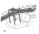
- Fig.3
- die rechte Endstation der Anlage gemäß Fig.1, mit einem Traggerüst, in axonometrischer Darstellung;
- Fig.4
- die Endstation gemäß Fig.3, in gegenüber dieser vergrößerter Darstellung;
- Fig. 5
- die Endstation gemäß Fig.3, in Draufsicht;
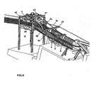
- Fig.6
- das in dieser Endstation befindliches Traggerüst, in axonometrischer Darstellung;
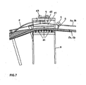
- Fig.7
- das in der linken Endstation gemäß Fig.1 vorgesehene Traggerüst, in Seitenansicht, und
- Fig.8
- Details des Traggerüstes gemäß Fig.7, in axonometrischer Darstellung.
- Eine erfindungsgemäße Anlage zur Förderung von Gütern weist zwei Endstationen 1 auf, zwischen welchen ein in sich geschlossenes Förderband 2 für den Transport von Schüttgütern, wie Baumaterialien, Abraummaterialien, Erzen u.dgl., bewegbar ist. Dabei dient die eine der Endstationen als Ladestation und die andere Endstation als Entladestation. Den beiden Trumen des Förderbandes 2 sind zwei Tragseile 3a, 3b zugeordnet, wobei das Förderband 2 mittels auf den Tragseilen 3 abrollender Tragrollen 4, welche auf Tragbügeln 5 gelagert sind, getragen ist und bewegt wird. In den Endstationen 1 und längs der Strecke sind Traggerüste 6 vorgesehen, über welche das Förderband 2 und die Tragseile 4 geführt sind. Weiters ist das Förderband 2 in den Endstationen 1 über Umlenktrommeln 7 geführt, welche um vertikal ausgerichtete Achsen verdrehbar sind. Dabei ist zumindest eine der Umlenktrommeln 7 mittels eines Antriebsmotors angetrieben.
- Wie dies aus Fig.2 ersichtlich ist, ist das Förderband 2 mit Wellkanten 21 ausgebildet. Aufgrund der in den Endstationen 1 erfolgenden Führung des Förderbandes 2 über die um vertikale Achsen verdrehbaren Umlenktrommeln 7 befinden sich die beiden Trume 2a und 2b des Förderbandes 2 in der gleichen Höhenlage. Die Tragbügel 5 sind angenähert L-förmig abgewinkelt, wobei die angenähert horizontalen Schenkel 51 mit dem Förderband 2 fest verbunden sind und am oberen Ende der schräg nach oben ragenden Schenkel 52 die Tragrollen 4 gelagert sind, welche am dem jeweiligen Trum 2a, 2b zugeordneten Tragseil 3a, 3b abrollen. An den nach oben abragenden Schenkeln 52 der Tragbügel 5 sind weiters quer abragende Führungsplatten 53 befestigt, welche sich unterhalb der Tragrollen 4 befinden und welche dazu dienen, Seilentgleisungen zu verhindern. Die Führungsplatten 53, welche aus Gummi hergestellt sind, weisen gegenüber Belastungen in Richtung ihrer Ebene eine hohe Steifigkeit auf, wodurch sie eine Führung der Laufrollen 4 an den Tragseilen 3a, 3b gewährleisten. Demgegenüber sind sie aus ihrer Ebene elastisch ausbiegbar, wodurch gewährleistet ist, dass in den Endstationen die Laufrollen 4 von den Tragseilen 3a, 3b abgehoben werden können.
- Wie dies insbesondere aus den Fig.3 bis 6 ersichtlich ist, ist das Förderband 2 in den Endstationen 1 über jeweils eine um eine vertikale Achse verdrehbare Umlenktrommel 7 geführt. Dabei wird das zur Umlenktrommel 7 hinbewegte Trum 2b des Förderbandes 2 aus der horizontalen Ebene in eine vertikale Ebene verschwenkt und wird es in dieser Lage um die Umlenktrommel 7 herum bewegt. In der Folge wird das von der Umlenktrommel 7 weg bewegte Trum 2a des Förderbandes 2 wieder in die horizontale Ebene verschwenkt. Die Verschwenkungen erfolgen dabei in derjenigen Weise, dass bei beiden Trumen 2b und 2a die Förderseite des Förderbandes 2 nach oben gerichtet ist. Die beiden Tragseile 3a, 3b sind im Fundament 10 der Endstation abgespannt.
- In den Endstationen 1 sind den Tragrollen 4 zugeordnete Führungsschienen 8 vorgesehen, durch welche die Verschwenkung des Förderbandes 2 in den Bereichen der Endstationen 1 der Anlage gesteuert wird. Zudem ist in den Bereichen zwischen den Traggerüsten 6 und den Umlenktrommeln 7 zwischen den beiden Tragseilen 3a und 3b ein Stützbalken 31 vorgesehen, durch welchen die beiden Seile 3a und 3b so voneinander im Abstand gehalten sind, dass dazwischen der für die Führungsschiene 8 erforderliche Platz zur Verfügung steht und weiters bei der Verschwenkung des Förderbandes 2 sowie der an diesem befestigten Bügel 5 und den an diesen gelagerten Tragrollen 4 vermieden wird, daß die Tragrollen 4 mit den Tragseilen 3a, 3b kollidieren.
- Wie dies aus den Fig.6 bis Fig. 8 ersichtlich ist, sind in den Traggerüsten 6 Abstützungen 61 vorgesehen, über welche die Tragseile 3a und 3b geführt sind und durch welche deren Höhenlage bestimmt ist. Die Abstützungen 61 sind dabei an Traggestellen 62 angeordnet, welche mittels Laufrollen 63 in der Richtung der Tragseile 3a, 3b verfahrbar sind. Hierdurch erfolgt ein Ausgleich der auf beiden Seiten der Stützen 6 auftretenden Seilkräfte. Derartige Abstützungen sind bei allen Traggerüsten 6 vorgesehen.
- Weiters sind in sämtlichen Traggerüsten 6 mehrere Stützwalzen 64 gelagert, über welche die beiden Trume 2a, 2b des Förderbandes 2 geführt sind, wodurch die Höhenlage des Förderbandes 2 bestimmt ist. Durch die Stützwalzen 64 werden die beiden Trume 2a und 2b des Förderbandes 2 abgestützt, wodurch die durch das Förderband 2 verursachten Belastungen unmittelbar von den Traggerüsten 6 aufgenommen werden. Hierdurch werden die Tragrollen 4 entlastet. Zudem wird das sich zur Umlenktrommel 7 hin bewegende Trum 2a des Förderbandes 2 im Bereich des Traggerüstes 6 angehoben. Die in den Endstationen vorgesehenen Führungsschienen 8 beginnen und enden oberhalb der Abstützungen 61 bzw. der Stützwalzen 64. Mit dem Förderband 2 werden auch die Tragrollen 4 angehoben, wodurch sie vom Tragseil 3a abgehoben werden und in die Führungsschienen 8 hinein geleitet werden, durch welche sie während ihrer Bewegung durch die Endstationen 1 hindurch geführt werden. Ebenso werden hierdurch die aus den Führungsschienen 8 herauslaufenden Tragrollen 4 so geführt, dass sie auf das auf die Abstützungen 61 aufliegende Tragseil 3b gelangen.
- Wie dies weiters aus Fig.8 ersichtlich ist, laufen bei der Bewegung in die Endstationen 1 die Führungsplatten 53 auf die Abstützungen 61 auf, wodurch sie aus ihrer Ebene herausgebogen werden. Hierdurch werden sie vom Tragseil 3a entfernt, wodurch die Tragrollen 4 vom Tragseil 3a abgehoben werden können. Ebenso werden die von den Endstationen 1 wegbewegten Führungsplatten 53 vorerst durch die Abstützungen 61 abgebogen und gelangen sie in der Folge wieder unter das Tragseil 2b. Die an den längs der Strecke befindlichen Traggerüsten 6 vorgesehenen Abstützungen 61 wirken in der gleichen Weise.
- Durch die Führungsschienen 8 wird die Schwenkbewegung des Förderbandes 2 aus dessen horizontaler Lage in dessen vertikale Lage und hierauffolgend wieder in die horizontale Lage gesteuert. Dabei erfolgt die Schwenkbewegung des Förderbandes 2 derart, dass auch bei dem von der Entladestation zur Ladestation sich zurückbewegenden Trum des Förderbandes 2 dessen Förderseite nach oben gerichtet ist. Hierdurch wird gewährleistet, dass am Förderband 2 verbliebene Anteile des Fördergutes am zurücklaufenden Trum des Förderbandes 2 verbleiben, wodurch auf Maßnahmen zum Schutz der unterhalb der Förderanlage befindlichen Bereiche verzichtet werden kann.
- Ergänzend wird darauf verwiesen, dass die Seitenwände des Förderbandes nicht als Wellkanten ausgebildet zu sein brauchen. Vielmehr können sie z.B. auch mit von oben nach unten durchgehenden Schlitzen ausgebildet sein, wodurch sie gleichfalls um die Umlenktrommeln herum bewegbar sind.
Weiters kann eine derartige Förderanlage auch so ausgebildet sein, dass beide Endstationen sowohl als Ladestation als auch als Entladestation ausgebildet sind, wobei mittels der beiden Trume eine Förderung von Gütern in beiden Bewegungsrichtungen des Förderbandes erfolgt.
Claims (8)
- Anlage zur Förderung von Gütern mittels eines in sich geschlossenen Förderbandes [2], welches in den Endstationen [1] über Umlenktrommeln (7) geführt ist und welches mit längs Tragseilen [3a, 3b] verfahrbaren Tragrollen (4) ausgebildet ist, dadurch gekennzeichnet, dass jedem Trum (2a, 2b) des Förderbandes (2) nur ein einziges, oberhalb des betreffenden Trumes (2a, 2b) befindliches Tragseil [3a, 3b] zugeordnet ist und dass am Förderband [2] nach oben abrageride Tragbügel (5) befestigt sind, an deren oberen Enden die Tragrollen (4) gelagert sind.
- Anlage nach Patentanspruch 1, dadurch gekennzeichnet, dass die in den Endstationen [1] befindlichen Umlenktrommeln [7] um angenähert vertikale Achsen verdrehbar sind.
- Anlage nach einem der Patentansprüche 1 und 2, dadurch gekennzeichnet, dass das Förderband (2) mit Wellkanten [21] ausgebildet ist.
- Anlage nach einem der Patentansprüche 1 bis 3, dadurch gekennzeichnet, dass die Tragbügel (5) abgewinkelt ausgebildet sind, wobei der angenähert waagrecht ausgerichtete Schenkel (51) mit dem Förderband (2) fest verbunden ist und am oberen Ende des von diesem Schenkel [51] nach oben abragenden zweiten Schenkels [52] mindestens eine Tragrolle (4) gelagert ist.
- Anlage nach einem der Patentansprüche 1 bis 4, dadurch gekennzeichnet, dass in den Endstationen (1) den Tragrollen (4) zugeordnete Führungsschienen (8) angeordnet sind, mittels welcher die Tragbügel (5) so geführt werden, dass das Förderband [2] aus seiner angenähert horizontalen Lage in eine angenähert vertikale Lage verschwenkt wird, in welcher es um die Umlenktrommeln [7] herumbewegt wird, worauf es wieder in die angenähert horizontale Lage verschwenkt wird, wobei bei beiden Trumen [2a, 2b] die Förderseite des Förderbandes (2) nach oben gerichtet ist.
- Anlage nach einem der Patentansprüche 1 bis 5, dadurch gekennzeichnet, dass an jedem Tragbügel [5] unterhalb der Tragrolle (4) eine insbesondere aus Gummi hergestellte Führungsplatte (53) vorgesehen ist.
- Anlage nach einem der Patentansprüche 1 bis 6, dadurch gekennzeichnet, dass die Tragseile (3a, 3b) im Bereich der Stützen (6) über Abstützungen (61) geführt sind, welche in Längsrichtung der Tragseile (3a, 3b) verfahrbar sind.
- Anlage nach einem der Patentansprüche 1 bis 7, dadurch gekennzeichnet, dass das Förderband (2) im Bereich der Stützen (6) über Stützwalzen (64) geführt ist.
Priority Applications (2)
| Application Number | Priority Date | Filing Date | Title |
|---|---|---|---|
| AT04450088T ATE325058T1 (de) | 2003-12-04 | 2004-04-14 | Anlage zur förderung von gütern mittels eines endlosen förderbandes |
| PL04450088T PL1538112T3 (pl) | 2003-12-04 | 2004-04-14 | Urządzenie do transportu towarów za pomocą taśmy przenośnikowej bez końca |
Applications Claiming Priority (2)
| Application Number | Priority Date | Filing Date | Title |
|---|---|---|---|
| AT19422003 | 2003-12-04 | ||
| AT19422003 | 2003-12-04 |
Publications (2)
| Publication Number | Publication Date |
|---|---|
| EP1538112A1 EP1538112A1 (de) | 2005-06-08 |
| EP1538112B1 true EP1538112B1 (de) | 2006-05-03 |
Family
ID=34200463
Family Applications (1)
| Application Number | Title | Priority Date | Filing Date |
|---|---|---|---|
| EP04450088A Expired - Lifetime EP1538112B1 (de) | 2003-12-04 | 2004-04-14 | Anlage zur Förderung von Gütern mittels eines endlosen Förderbandes |
Country Status (16)
| Country | Link |
|---|---|
| US (1) | US6863174B1 (de) |
| EP (1) | EP1538112B1 (de) |
| JP (1) | JP4338598B2 (de) |
| KR (1) | KR100660675B1 (de) |
| CN (1) | CN100473593C (de) |
| AT (1) | ATE325058T1 (de) |
| AU (1) | AU2004202295B2 (de) |
| BR (1) | BRPI0401952B1 (de) |
| CA (1) | CA2470894C (de) |
| DE (1) | DE502004000509D1 (de) |
| ES (1) | ES2260744T3 (de) |
| NZ (1) | NZ533071A (de) |
| PL (1) | PL1538112T3 (de) |
| PT (1) | PT1538112E (de) |
| RU (1) | RU2004116115A (de) |
| ZA (1) | ZA200407588B (de) |
Cited By (1)
| Publication number | Priority date | Publication date | Assignee | Title |
|---|---|---|---|---|
| WO2024110443A1 (de) | 2022-11-23 | 2024-05-30 | Innova Patent Gmbh | Fördereinrichtung |
Families Citing this family (11)
| Publication number | Priority date | Publication date | Assignee | Title |
|---|---|---|---|---|
| AT501900B1 (de) * | 2005-07-13 | 2006-12-15 | Voest Alpine Materials Handlin | Abfördereinrichtung für die kontinuierliche abförderung von untertägig abgebautem material |
| DE102006016644A1 (de) * | 2006-04-08 | 2007-10-11 | Dürr Systems GmbH | Vorrichtung zum Zuführen von Medien zu Bearbeitungsplätzen |
| RU2336214C1 (ru) * | 2007-06-09 | 2008-10-20 | Государственное образовательное учреждение высшего профессионального образования "Санкт-Петербургский государственный горный институт имени Г.В. Плеханова (технический университет)" | Ленточно-канатный конвейер |
| RU2340529C1 (ru) * | 2007-06-20 | 2008-12-10 | Государственное образовательное учреждение высшего профессионального образования "Санкт-Петербургский государственный горный институт имени Г.В. Плеханова (технический университет)" | Ленточно-канатный конвейер |
| EP2030919B1 (de) * | 2007-08-27 | 2012-04-04 | Innova Patent GmbH | Förderanlage zum Transport von Gütern mittels eines Förderbandes |
| AT506825B1 (de) | 2008-05-27 | 2010-02-15 | Innova Patent Gmbh | Vorrichtung zum erkennen einer fehllage eines tragseils einer seilbahn |
| CN102491047B (zh) * | 2011-11-11 | 2013-07-10 | 张志琳 | 索道桥的带式输送机 |
| CN104016282B (zh) * | 2014-06-12 | 2016-04-20 | 中建六局工业设备安装有限公司 | 一种能够适用狭小空间的多向长距离运输就位方法 |
| EP3307655B1 (de) | 2015-06-15 | 2019-08-14 | Sandvik Intellectual Property AB | Aufstellbare konstruktion in form einer vorrichtung zur umlenkung eines bandes und verfahren zum umlenken eines bandes |
| CN106743145A (zh) * | 2017-03-07 | 2017-05-31 | 哈尔滨纳诺机械设备有限公司 | 一种封闭式输送机 |
| CN109928230A (zh) * | 2019-05-05 | 2019-06-25 | 武汉明华鸿昌新型建材有限责任公司 | 一种骨料传送机构 |
Family Cites Families (7)
| Publication number | Priority date | Publication date | Assignee | Title |
|---|---|---|---|---|
| US4380288A (en) * | 1976-07-02 | 1983-04-19 | Joy Manufacturing Company | Conveyor |
| DE3308918C1 (de) * | 1983-03-12 | 1984-10-25 | Friedrich Wilhelm Paurat | Vorrichtung fuer den Transport von Personen und Material in einer Strecke eines bergbaulichen Untertagebetriebes |
| CN2033392U (zh) * | 1988-04-07 | 1989-03-01 | 王�泓 | 可弯曲胶带输送机 |
| AT405817B (de) * | 1995-06-01 | 1999-11-25 | Doppelmayr & Sohn | Förderanlage zum transport von gütern mittels eines förderbandes od.dgl. |
| US5699894A (en) * | 1995-10-06 | 1997-12-23 | Fmc Corporation | Cable driven conveyor system |
| AT405396B (de) * | 1997-04-08 | 1999-07-26 | Doppelmayr & Sohn | Förderanlage zum transport von gütern |
| AT409116B (de) * | 1998-07-14 | 2002-05-27 | Innova Patent Gmbh | Anlage für den transport von schüttgut |
-
2004
- 2004-04-14 PT PT04450088T patent/PT1538112E/pt unknown
- 2004-04-14 ES ES04450088T patent/ES2260744T3/es not_active Expired - Lifetime
- 2004-04-14 DE DE502004000509T patent/DE502004000509D1/de not_active Expired - Lifetime
- 2004-04-14 EP EP04450088A patent/EP1538112B1/de not_active Expired - Lifetime
- 2004-04-14 AT AT04450088T patent/ATE325058T1/de active
- 2004-04-14 PL PL04450088T patent/PL1538112T3/pl unknown
- 2004-05-20 NZ NZ533071A patent/NZ533071A/en not_active IP Right Cessation
- 2004-05-21 US US10/850,926 patent/US6863174B1/en not_active Expired - Lifetime
- 2004-05-26 AU AU2004202295A patent/AU2004202295B2/en not_active Ceased
- 2004-05-26 RU RU2004116115/11A patent/RU2004116115A/ru not_active Application Discontinuation
- 2004-05-27 KR KR1020040037757A patent/KR100660675B1/ko not_active Expired - Fee Related
- 2004-06-11 BR BRPI0401952-0A patent/BRPI0401952B1/pt not_active IP Right Cessation
- 2004-06-14 CA CA002470894A patent/CA2470894C/en not_active Expired - Fee Related
- 2004-06-23 CN CNB2004100499707A patent/CN100473593C/zh not_active Expired - Fee Related
- 2004-06-23 JP JP2004185304A patent/JP4338598B2/ja not_active Expired - Fee Related
- 2004-09-21 ZA ZA200407588A patent/ZA200407588B/xx unknown
Cited By (1)
| Publication number | Priority date | Publication date | Assignee | Title |
|---|---|---|---|---|
| WO2024110443A1 (de) | 2022-11-23 | 2024-05-30 | Innova Patent Gmbh | Fördereinrichtung |
Also Published As
| Publication number | Publication date |
|---|---|
| BRPI0401952A (pt) | 2005-08-23 |
| US6863174B1 (en) | 2005-03-08 |
| DE502004000509D1 (de) | 2006-06-08 |
| ES2260744T3 (es) | 2006-11-01 |
| JP2005162477A (ja) | 2005-06-23 |
| PT1538112E (pt) | 2006-06-30 |
| CN100473593C (zh) | 2009-04-01 |
| PL1538112T3 (pl) | 2006-09-29 |
| AU2004202295B2 (en) | 2010-09-23 |
| KR20050054430A (ko) | 2005-06-10 |
| ATE325058T1 (de) | 2006-06-15 |
| RU2004116115A (ru) | 2005-11-10 |
| AU2004202295A1 (en) | 2005-06-23 |
| ZA200407588B (en) | 2005-07-19 |
| NZ533071A (en) | 2005-11-25 |
| KR100660675B1 (ko) | 2006-12-21 |
| CN1623868A (zh) | 2005-06-08 |
| JP4338598B2 (ja) | 2009-10-07 |
| BRPI0401952B1 (pt) | 2015-09-01 |
| CA2470894A1 (en) | 2005-06-04 |
| CA2470894C (en) | 2008-08-26 |
| EP1538112A1 (de) | 2005-06-08 |
Similar Documents
| Publication | Publication Date | Title |
|---|---|---|
| AT403271B (de) | Einrichtung an einer rollenbahn | |
| EP1452466B1 (de) | Förderanlage zum Transport von Gütern | |
| EP2030919B1 (de) | Förderanlage zum Transport von Gütern mittels eines Förderbandes | |
| EP2460745B1 (de) | Förderanlage zum Transport von Schüttgütern | |
| AT505925B1 (de) | Förderanlage zum transport von gütern mit einem förderband | |
| EP1538112B1 (de) | Anlage zur Förderung von Gütern mittels eines endlosen Förderbandes | |
| AT405817B (de) | Förderanlage zum transport von gütern mittels eines förderbandes od.dgl. | |
| DE3315078C2 (de) | Bandförderer für die senkrechte oder steile Förderung von Schüttgut | |
| DE3426106C2 (de) | Bandförderer | |
| EP2484607B1 (de) | Tragbahnförderer und Förderanlage mit einem solchen | |
| EP2019055B1 (de) | Lagereinheit für eine Förderanlage zum Transport von Gütern mittels eines Förderbandes | |
| AT511795B1 (de) | Förderanlage zum transport von schüttgütern | |
| EP2019054A1 (de) | Förderanlage zum Transport von Gütern | |
| EP0949163B1 (de) | Anlage zur Förderung von Gütern mittels eines endlosen Förderbandes od.dgl. | |
| EP2349876A1 (de) | Förderband für eine streckenförderanlage auf tragseilen oder längsschienen | |
| EP0166769B1 (de) | Gurtförderanlage | |
| AT390775B (de) | Gurtfoerdereinrichtung | |
| AT519207A1 (de) | Fördereinrichtung zum Fördern von Produkten | |
| DE8535683U1 (de) | Fördereinrichtung mit angetriebenen, armierten Gurten zum Transport von beladenen Paletten | |
| AT12489U1 (de) | Förderanlage zum transport von schüttgütern | |
| AT405818B (de) | Anlage zur förderung von gütern bzw. von personen mittels eines in sich geschlossenen förderbandes od.dgl. | |
| EP1623951B1 (de) | Hubvorrichtung | |
| DE102018102752A1 (de) | Heber mit mindestens einer vertikal verfahrbaren Hubplattform mit einem Riemenantrieb | |
| EP0423145B1 (de) | Wendelförderer zum be- und entladen von stückgut | |
| DE20306656U1 (de) | Einrichtung zum Verteilen von Stückgut |
Legal Events
| Date | Code | Title | Description |
|---|---|---|---|
| PUAI | Public reference made under article 153(3) epc to a published international application that has entered the european phase |
Free format text: ORIGINAL CODE: 0009012 |
|
| AK | Designated contracting states |
Kind code of ref document: A1 Designated state(s): AT BE BG CH CY CZ DE DK EE ES FI FR GB GR HU IE IT LI LU MC NL PL PT RO SE SI SK TR |
|
| AX | Request for extension of the european patent |
Extension state: AL HR LT LV MK |
|
| 17P | Request for examination filed |
Effective date: 20050701 |
|
| GRAP | Despatch of communication of intention to grant a patent |
Free format text: ORIGINAL CODE: EPIDOSNIGR1 |
|
| GRAS | Grant fee paid |
Free format text: ORIGINAL CODE: EPIDOSNIGR3 |
|
| AKX | Designation fees paid |
Designated state(s): AT BE BG CH CY CZ DE DK EE ES FI FR GB GR HU IE IT LI LU MC NL PL PT RO SE SI SK TR |
|
| GRAA | (expected) grant |
Free format text: ORIGINAL CODE: 0009210 |
|
| AK | Designated contracting states |
Kind code of ref document: B1 Designated state(s): AT BE BG CH CY CZ DE DK EE ES FI FR GB GR HU IE IT LI LU MC NL PL PT RO SE SI SK TR |
|
| PG25 | Lapsed in a contracting state [announced via postgrant information from national office to epo] |
Ref country code: IT Free format text: LAPSE BECAUSE OF FAILURE TO SUBMIT A TRANSLATION OF THE DESCRIPTION OR TO PAY THE FEE WITHIN THE PRESCRIBED TIME-LIMIT;WARNING: LAPSES OF ITALIAN PATENTS WITH EFFECTIVE DATE BEFORE 2007 MAY HAVE OCCURRED AT ANY TIME BEFORE 2007. THE CORRECT EFFECTIVE DATE MAY BE DIFFERENT FROM THE ONE RECORDED. Effective date: 20060503 Ref country code: CZ Free format text: LAPSE BECAUSE OF FAILURE TO SUBMIT A TRANSLATION OF THE DESCRIPTION OR TO PAY THE FEE WITHIN THE PRESCRIBED TIME-LIMIT Effective date: 20060503 Ref country code: SK Free format text: LAPSE BECAUSE OF FAILURE TO SUBMIT A TRANSLATION OF THE DESCRIPTION OR TO PAY THE FEE WITHIN THE PRESCRIBED TIME-LIMIT Effective date: 20060503 Ref country code: IE Free format text: LAPSE BECAUSE OF FAILURE TO SUBMIT A TRANSLATION OF THE DESCRIPTION OR TO PAY THE FEE WITHIN THE PRESCRIBED TIME-LIMIT Effective date: 20060503 Ref country code: RO Free format text: LAPSE BECAUSE OF FAILURE TO SUBMIT A TRANSLATION OF THE DESCRIPTION OR TO PAY THE FEE WITHIN THE PRESCRIBED TIME-LIMIT Effective date: 20060503 Ref country code: FI Free format text: LAPSE BECAUSE OF FAILURE TO SUBMIT A TRANSLATION OF THE DESCRIPTION OR TO PAY THE FEE WITHIN THE PRESCRIBED TIME-LIMIT Effective date: 20060503 Ref country code: SI Free format text: LAPSE BECAUSE OF FAILURE TO SUBMIT A TRANSLATION OF THE DESCRIPTION OR TO PAY THE FEE WITHIN THE PRESCRIBED TIME-LIMIT Effective date: 20060503 |
|
| REG | Reference to a national code |
Ref country code: GB Ref legal event code: FG4D Free format text: NOT ENGLISH |
|
| REG | Reference to a national code |
Ref country code: SE Ref legal event code: TRGR |
|
| REG | Reference to a national code |
Ref country code: CH Ref legal event code: NV Representative=s name: LUCHS & PARTNER PATENTANWAELTE Ref country code: CH Ref legal event code: EP |
|
| GBT | Gb: translation of ep patent filed (gb section 77(6)(a)/1977) |
Effective date: 20060504 |
|
| REF | Corresponds to: |
Ref document number: 502004000509 Country of ref document: DE Date of ref document: 20060608 Kind code of ref document: P |
|
| REG | Reference to a national code |
Ref country code: IE Ref legal event code: FG4D Free format text: LANGUAGE OF EP DOCUMENT: GERMAN |
|
| REG | Reference to a national code |
Ref country code: PT Ref legal event code: SC4A Effective date: 20060509 |
|
| PG25 | Lapsed in a contracting state [announced via postgrant information from national office to epo] |
Ref country code: DK Free format text: LAPSE BECAUSE OF FAILURE TO SUBMIT A TRANSLATION OF THE DESCRIPTION OR TO PAY THE FEE WITHIN THE PRESCRIBED TIME-LIMIT Effective date: 20060803 |
|
| REG | Reference to a national code |
Ref country code: ES Ref legal event code: FG2A Ref document number: 2260744 Country of ref document: ES Kind code of ref document: T3 |
|
| ET | Fr: translation filed | ||
| REG | Reference to a national code |
Ref country code: IE Ref legal event code: FD4D |
|
| PLBE | No opposition filed within time limit |
Free format text: ORIGINAL CODE: 0009261 |
|
| STAA | Information on the status of an ep patent application or granted ep patent |
Free format text: STATUS: NO OPPOSITION FILED WITHIN TIME LIMIT |
|
| 26N | No opposition filed |
Effective date: 20070206 |
|
| PG25 | Lapsed in a contracting state [announced via postgrant information from national office to epo] |
Ref country code: GR Free format text: LAPSE BECAUSE OF FAILURE TO SUBMIT A TRANSLATION OF THE DESCRIPTION OR TO PAY THE FEE WITHIN THE PRESCRIBED TIME-LIMIT Effective date: 20060804 |
|
| PG25 | Lapsed in a contracting state [announced via postgrant information from national office to epo] |
Ref country code: BG Free format text: LAPSE BECAUSE OF FAILURE TO SUBMIT A TRANSLATION OF THE DESCRIPTION OR TO PAY THE FEE WITHIN THE PRESCRIBED TIME-LIMIT Effective date: 20060803 |
|
| PG25 | Lapsed in a contracting state [announced via postgrant information from national office to epo] |
Ref country code: EE Free format text: LAPSE BECAUSE OF FAILURE TO SUBMIT A TRANSLATION OF THE DESCRIPTION OR TO PAY THE FEE WITHIN THE PRESCRIBED TIME-LIMIT Effective date: 20060503 |
|
| PGRI | Patent reinstated in contracting state [announced from national office to epo] |
Ref country code: IT Effective date: 20080601 |
|
| PG25 | Lapsed in a contracting state [announced via postgrant information from national office to epo] |
Ref country code: MC Free format text: LAPSE BECAUSE OF NON-PAYMENT OF DUE FEES Effective date: 20070430 |
|
| PG25 | Lapsed in a contracting state [announced via postgrant information from national office to epo] |
Ref country code: LU Free format text: LAPSE BECAUSE OF NON-PAYMENT OF DUE FEES Effective date: 20070414 Ref country code: CY Free format text: LAPSE BECAUSE OF FAILURE TO SUBMIT A TRANSLATION OF THE DESCRIPTION OR TO PAY THE FEE WITHIN THE PRESCRIBED TIME-LIMIT Effective date: 20060503 |
|
| PG25 | Lapsed in a contracting state [announced via postgrant information from national office to epo] |
Ref country code: TR Free format text: LAPSE BECAUSE OF FAILURE TO SUBMIT A TRANSLATION OF THE DESCRIPTION OR TO PAY THE FEE WITHIN THE PRESCRIBED TIME-LIMIT Effective date: 20060503 Ref country code: HU Free format text: LAPSE BECAUSE OF FAILURE TO SUBMIT A TRANSLATION OF THE DESCRIPTION OR TO PAY THE FEE WITHIN THE PRESCRIBED TIME-LIMIT Effective date: 20061104 |
|
| REG | Reference to a national code |
Ref country code: FR Ref legal event code: PLFP Year of fee payment: 13 |
|
| PGFP | Annual fee paid to national office [announced via postgrant information from national office to epo] |
Ref country code: AT Payment date: 20160428 Year of fee payment: 13 |
|
| REG | Reference to a national code |
Ref country code: FR Ref legal event code: PLFP Year of fee payment: 14 |
|
| PGFP | Annual fee paid to national office [announced via postgrant information from national office to epo] |
Ref country code: PL Payment date: 20170323 Year of fee payment: 14 |
|
| PGFP | Annual fee paid to national office [announced via postgrant information from national office to epo] |
Ref country code: NL Payment date: 20170419 Year of fee payment: 14 |
|
| PGFP | Annual fee paid to national office [announced via postgrant information from national office to epo] |
Ref country code: CH Payment date: 20170419 Year of fee payment: 14 Ref country code: DE Payment date: 20170419 Year of fee payment: 14 Ref country code: FR Payment date: 20170419 Year of fee payment: 14 Ref country code: GB Payment date: 20170419 Year of fee payment: 14 |
|
| PGFP | Annual fee paid to national office [announced via postgrant information from national office to epo] |
Ref country code: BE Payment date: 20170419 Year of fee payment: 14 Ref country code: PT Payment date: 20170412 Year of fee payment: 14 Ref country code: IT Payment date: 20170424 Year of fee payment: 14 Ref country code: ES Payment date: 20170510 Year of fee payment: 14 Ref country code: SE Payment date: 20170419 Year of fee payment: 14 |
|
| REG | Reference to a national code |
Ref country code: AT Ref legal event code: MM01 Ref document number: 325058 Country of ref document: AT Kind code of ref document: T Effective date: 20170414 |
|
| PG25 | Lapsed in a contracting state [announced via postgrant information from national office to epo] |
Ref country code: AT Free format text: LAPSE BECAUSE OF NON-PAYMENT OF DUE FEES Effective date: 20170414 |
|
| REG | Reference to a national code |
Ref country code: DE Ref legal event code: R119 Ref document number: 502004000509 Country of ref document: DE |
|
| REG | Reference to a national code |
Ref country code: CH Ref legal event code: PL |
|
| REG | Reference to a national code |
Ref country code: SE Ref legal event code: EUG |
|
| REG | Reference to a national code |
Ref country code: NL Ref legal event code: MM Effective date: 20180501 |
|
| REG | Reference to a national code |
Ref country code: BE Ref legal event code: MM Effective date: 20180430 |
|
| GBPC | Gb: european patent ceased through non-payment of renewal fee |
Effective date: 20180414 |
|
| PG25 | Lapsed in a contracting state [announced via postgrant information from national office to epo] |
Ref country code: DE Free format text: LAPSE BECAUSE OF NON-PAYMENT OF DUE FEES Effective date: 20181101 Ref country code: PT Free format text: LAPSE BECAUSE OF NON-PAYMENT OF DUE FEES Effective date: 20181015 Ref country code: NL Free format text: LAPSE BECAUSE OF NON-PAYMENT OF DUE FEES Effective date: 20180501 Ref country code: SE Free format text: LAPSE BECAUSE OF NON-PAYMENT OF DUE FEES Effective date: 20180415 |
|
| PG25 | Lapsed in a contracting state [announced via postgrant information from national office to epo] |
Ref country code: GB Free format text: LAPSE BECAUSE OF NON-PAYMENT OF DUE FEES Effective date: 20180414 Ref country code: CH Free format text: LAPSE BECAUSE OF NON-PAYMENT OF DUE FEES Effective date: 20180430 Ref country code: LI Free format text: LAPSE BECAUSE OF NON-PAYMENT OF DUE FEES Effective date: 20180430 Ref country code: BE Free format text: LAPSE BECAUSE OF NON-PAYMENT OF DUE FEES Effective date: 20180430 |
|
| PG25 | Lapsed in a contracting state [announced via postgrant information from national office to epo] |
Ref country code: IT Free format text: LAPSE BECAUSE OF FAILURE TO SUBMIT A TRANSLATION OF THE DESCRIPTION OR TO PAY THE FEE WITHIN THE PRESCRIBED TIME-LIMIT Effective date: 20180414 Ref country code: FR Free format text: LAPSE BECAUSE OF NON-PAYMENT OF DUE FEES Effective date: 20180430 |
|
| REG | Reference to a national code |
Ref country code: ES Ref legal event code: FD2A Effective date: 20190912 |
|
| PG25 | Lapsed in a contracting state [announced via postgrant information from national office to epo] |
Ref country code: ES Free format text: LAPSE BECAUSE OF NON-PAYMENT OF DUE FEES Effective date: 20180415 |
|
| PG25 | Lapsed in a contracting state [announced via postgrant information from national office to epo] |
Ref country code: PL Free format text: LAPSE BECAUSE OF NON-PAYMENT OF DUE FEES Effective date: 20180414 |