EP1537367B1 - Evaporateur a deux etages a sous-refroidissement de fluide et surchauffe de vapeur d'aspiration integres dans une installation modulaire regulee en frequence - Google Patents
Evaporateur a deux etages a sous-refroidissement de fluide et surchauffe de vapeur d'aspiration integres dans une installation modulaire regulee en frequence Download PDFInfo
- Publication number
- EP1537367B1 EP1537367B1 EP02754098A EP02754098A EP1537367B1 EP 1537367 B1 EP1537367 B1 EP 1537367B1 EP 02754098 A EP02754098 A EP 02754098A EP 02754098 A EP02754098 A EP 02754098A EP 1537367 B1 EP1537367 B1 EP 1537367B1
- Authority
- EP
- European Patent Office
- Prior art keywords
- refrigeration
- refrigerant
- stage
- evaporator
- liquid
- Prior art date
- Legal status (The legal status is an assumption and is not a legal conclusion. Google has not performed a legal analysis and makes no representation as to the accuracy of the status listed.)
- Expired - Lifetime
Links
- 239000007788 liquid Substances 0.000 title claims abstract description 37
- 238000001704 evaporation Methods 0.000 title claims description 21
- 230000008020 evaporation Effects 0.000 title claims description 20
- 238000005516 engineering process Methods 0.000 title description 14
- 239000003507 refrigerant Substances 0.000 claims description 63
- 238000005057 refrigeration Methods 0.000 claims description 58
- 238000004781 supercooling Methods 0.000 claims description 15
- 238000002347 injection Methods 0.000 claims description 13
- 239000007924 injection Substances 0.000 claims description 13
- 239000002918 waste heat Substances 0.000 claims description 10
- 238000000034 method Methods 0.000 claims description 9
- 239000007789 gas Substances 0.000 claims description 8
- 238000013461 design Methods 0.000 claims description 5
- 238000003860 storage Methods 0.000 claims description 4
- 239000000203 mixture Substances 0.000 claims description 3
- 238000011144 upstream manufacturing Methods 0.000 claims description 3
- 239000013526 supercooled liquid Substances 0.000 claims description 2
- 239000003673 groundwater Substances 0.000 claims 1
- 239000000126 substance Substances 0.000 claims 1
- 238000001816 cooling Methods 0.000 abstract description 19
- 238000009434 installation Methods 0.000 abstract 2
- 239000002826 coolant Substances 0.000 abstract 1
- 238000011161 development Methods 0.000 description 6
- 230000018109 developmental process Effects 0.000 description 6
- 239000003921 oil Substances 0.000 description 5
- 238000012423 maintenance Methods 0.000 description 4
- 238000010438 heat treatment Methods 0.000 description 3
- 238000005457 optimization Methods 0.000 description 3
- 230000035484 reaction time Effects 0.000 description 3
- 238000011084 recovery Methods 0.000 description 3
- 230000006978 adaptation Effects 0.000 description 2
- 238000006243 chemical reaction Methods 0.000 description 2
- 238000005265 energy consumption Methods 0.000 description 2
- 238000004146 energy storage Methods 0.000 description 2
- 230000010354 integration Effects 0.000 description 2
- 238000013021 overheating Methods 0.000 description 2
- 239000000243 solution Substances 0.000 description 2
- 238000012546 transfer Methods 0.000 description 2
- XLYOFNOQVPJJNP-UHFFFAOYSA-N water Substances O XLYOFNOQVPJJNP-UHFFFAOYSA-N 0.000 description 2
- 239000003570 air Substances 0.000 description 1
- 230000005494 condensation Effects 0.000 description 1
- 238000009833 condensation Methods 0.000 description 1
- 238000010276 construction Methods 0.000 description 1
- 238000010586 diagram Methods 0.000 description 1
- 238000006073 displacement reaction Methods 0.000 description 1
- 238000009826 distribution Methods 0.000 description 1
- 238000007710 freezing Methods 0.000 description 1
- 230000008014 freezing Effects 0.000 description 1
- 239000011521 glass Substances 0.000 description 1
- 230000003993 interaction Effects 0.000 description 1
- 230000033772 system development Effects 0.000 description 1
Images


Classifications
-
- F—MECHANICAL ENGINEERING; LIGHTING; HEATING; WEAPONS; BLASTING
- F25—REFRIGERATION OR COOLING; COMBINED HEATING AND REFRIGERATION SYSTEMS; HEAT PUMP SYSTEMS; MANUFACTURE OR STORAGE OF ICE; LIQUEFACTION SOLIDIFICATION OF GASES
- F25B—REFRIGERATION MACHINES, PLANTS OR SYSTEMS; COMBINED HEATING AND REFRIGERATION SYSTEMS; HEAT PUMP SYSTEMS
- F25B5/00—Compression machines, plants or systems, with several evaporator circuits, e.g. for varying refrigerating capacity
- F25B5/04—Compression machines, plants or systems, with several evaporator circuits, e.g. for varying refrigerating capacity arranged in series
-
- F—MECHANICAL ENGINEERING; LIGHTING; HEATING; WEAPONS; BLASTING
- F25—REFRIGERATION OR COOLING; COMBINED HEATING AND REFRIGERATION SYSTEMS; HEAT PUMP SYSTEMS; MANUFACTURE OR STORAGE OF ICE; LIQUEFACTION SOLIDIFICATION OF GASES
- F25B—REFRIGERATION MACHINES, PLANTS OR SYSTEMS; COMBINED HEATING AND REFRIGERATION SYSTEMS; HEAT PUMP SYSTEMS
- F25B25/00—Machines, plants or systems, using a combination of modes of operation covered by two or more of the groups F25B1/00 - F25B23/00
- F25B25/005—Machines, plants or systems, using a combination of modes of operation covered by two or more of the groups F25B1/00 - F25B23/00 using primary and secondary systems
-
- F—MECHANICAL ENGINEERING; LIGHTING; HEATING; WEAPONS; BLASTING
- F25—REFRIGERATION OR COOLING; COMBINED HEATING AND REFRIGERATION SYSTEMS; HEAT PUMP SYSTEMS; MANUFACTURE OR STORAGE OF ICE; LIQUEFACTION SOLIDIFICATION OF GASES
- F25B—REFRIGERATION MACHINES, PLANTS OR SYSTEMS; COMBINED HEATING AND REFRIGERATION SYSTEMS; HEAT PUMP SYSTEMS
- F25B40/00—Subcoolers, desuperheaters or superheaters
-
- F—MECHANICAL ENGINEERING; LIGHTING; HEATING; WEAPONS; BLASTING
- F25—REFRIGERATION OR COOLING; COMBINED HEATING AND REFRIGERATION SYSTEMS; HEAT PUMP SYSTEMS; MANUFACTURE OR STORAGE OF ICE; LIQUEFACTION SOLIDIFICATION OF GASES
- F25B—REFRIGERATION MACHINES, PLANTS OR SYSTEMS; COMBINED HEATING AND REFRIGERATION SYSTEMS; HEAT PUMP SYSTEMS
- F25B2400/00—General features or devices for refrigeration machines, plants or systems, combined heating and refrigeration systems or heat-pump systems, i.e. not limited to a particular subgroup of F25B
- F25B2400/06—Several compression cycles arranged in parallel
-
- F—MECHANICAL ENGINEERING; LIGHTING; HEATING; WEAPONS; BLASTING
- F25—REFRIGERATION OR COOLING; COMBINED HEATING AND REFRIGERATION SYSTEMS; HEAT PUMP SYSTEMS; MANUFACTURE OR STORAGE OF ICE; LIQUEFACTION SOLIDIFICATION OF GASES
- F25B—REFRIGERATION MACHINES, PLANTS OR SYSTEMS; COMBINED HEATING AND REFRIGERATION SYSTEMS; HEAT PUMP SYSTEMS
- F25B2400/00—General features or devices for refrigeration machines, plants or systems, combined heating and refrigeration systems or heat-pump systems, i.e. not limited to a particular subgroup of F25B
- F25B2400/21—Modules for refrigeration systems
-
- F—MECHANICAL ENGINEERING; LIGHTING; HEATING; WEAPONS; BLASTING
- F25—REFRIGERATION OR COOLING; COMBINED HEATING AND REFRIGERATION SYSTEMS; HEAT PUMP SYSTEMS; MANUFACTURE OR STORAGE OF ICE; LIQUEFACTION SOLIDIFICATION OF GASES
- F25B—REFRIGERATION MACHINES, PLANTS OR SYSTEMS; COMBINED HEATING AND REFRIGERATION SYSTEMS; HEAT PUMP SYSTEMS
- F25B2600/00—Control issues
- F25B2600/02—Compressor control
- F25B2600/021—Inverters therefor
-
- Y—GENERAL TAGGING OF NEW TECHNOLOGICAL DEVELOPMENTS; GENERAL TAGGING OF CROSS-SECTIONAL TECHNOLOGIES SPANNING OVER SEVERAL SECTIONS OF THE IPC; TECHNICAL SUBJECTS COVERED BY FORMER USPC CROSS-REFERENCE ART COLLECTIONS [XRACs] AND DIGESTS
- Y02—TECHNOLOGIES OR APPLICATIONS FOR MITIGATION OR ADAPTATION AGAINST CLIMATE CHANGE
- Y02B—CLIMATE CHANGE MITIGATION TECHNOLOGIES RELATED TO BUILDINGS, e.g. HOUSING, HOUSE APPLIANCES OR RELATED END-USER APPLICATIONS
- Y02B30/00—Energy efficient heating, ventilation or air conditioning [HVAC]
- Y02B30/70—Efficient control or regulation technologies, e.g. for control of refrigerant flow, motor or heating
Definitions
- Refrigeration and freezing systems refrigeration technology, chiller for cooling and heating operation, refrigeration systems, refrigeration sets, heat pumps, energy recovery, waste heat recovery: modular technology, which is used for cooling and / or heating of various media such as liquids, air, gases or other energy sources.
- Frequency-controlled refrigerant compressors, refrigeration units, supercooling, energy storage are individually, but not in the combination, as presented here known and know in this combination, the use of the newly invented and here also pending registered two-stage evaporator with integrated liquid supercooling and Saugdampfschreibhitzung not.
- the aim of the invention is, in cooling / Triefkühlanlagen, chillers for cooling and heating operation, refrigeration systems, chillers, heat pumps and all systems with the use of refrigerants and refrigerants to achieve the following: Deep energy consumption, high reliability, high availability of cold, low service costs , fast reaction time (until the damage is repaired, whatever the nature of the damage), simple plant technology, simple system development, low investment costs, protection of investment, great independence (of products, refrigerants, etc.).
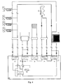
- the invention is based on the combination and further development of the above systems in modular refrigeration systems (11) (refrigeration sets).
- module technology (11) refrigeration sets
- module technology (11) we mean a ready-to-connect refrigeration system per module (11) (refrigeration unit) whereby the modules (11) are connected in parallel with each other to form a refrigeration system.
- modules (11) Various power ratings of modules (11) are used and several modules (11) can be connected to a refrigeration system.
- a system may be started with one or more modules (11) and later removed by further modules (11).
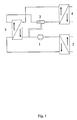
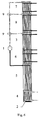
- Refrigerant compressor performance is significantly enhanced by the use of a special two-stage evaporator with integrated liquid subcooling and superheated steam overheating (4/5).
- the missing refrigeration capacity is partially or completely compensated for via the speed increase of the other refrigerant compressors (frequency control) (10).
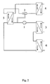
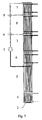
- the stored cooling energy (12/27) is used for liquid subcooling of the refrigerant (external supercooling) (6/27).
- Dry expansion systems dry evaporator with injection valve are known in which an overheated and gaseous refrigerant leaves the evaporator (20).
- Thermosyphone systems are known (flooded evaporator), in which liquid refrigerant is fed into the evaporator and superheated, gaseous or not superheated and provided with liquid components refrigerant flows into a separator and is guided from there in gaseous form and without liquid components to the refrigerant compressor.
- New to our invention is that the refrigerant enters as a liquid / gas mixture with a high gas content in a second evaporation stage (5/21) (dry evaporator), in which a residual evaporation followed by high superheating of the refrigerant (22) and a simultaneous supercooling of the liquid refrigerant takes place on the second side of the heat exchanger (23).
- a second evaporation stage (5/21) (dry evaporator)
- a residual evaporation followed by high superheating of the refrigerant (22) and a simultaneous supercooling of the liquid refrigerant takes place on the second side of the heat exchanger (23).
- the expansion valve (2) used outside or inside the evaporator restricts the size of the suction steam temperature at the inlet of the refrigerant compressor (1/22) and at the same time reduces the power of the internal subcooling (5/23) Available evaporator capacity (5/24) of the first stage (4/25) controls.
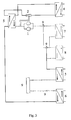
- New to our invention is also the interaction of all these components such as modular construction (11) (refrigeration charge), frequency control of the refrigerant compressor (10), parallel circuit of the refrigerant compressor circuits, two-stage evaporation with internal liquid supercooling and Saugdampfschreibhitzung (4/5), two- or Mehrgenunterkühlung ( 5/6), relocation and storage of the refrigeration energy of times with little need for times of high demand (12/27), integrated waste heat utilization (7/8), whereby due to the internal supercooling (5/23) higher temperatures for waste heat utilization (7/8) / 8/26). Combinations of all types of waste heat utilization, cascade and emergency operation at module, system or system level are possible.
- Requirement for the module technology (11) is maximum operational safety, low operating costs, low maintenance costs, simple system technology, simple performance adjustment to required cooling capacity (expansion stages) and simple and flexible adaptation to possible waste heat utilization (7/8).
- Energy saving on 3 levels is achieved by multilevel supercooling (5/6), by power shifting (for example, from day to night (12/27) and frequency control (10) which results in low operating costs.
- the remaining modules (11) take over part of the missing cooling capacity in case of failure of a module via the frequency conversion (10).
- emergency cooling for subcooling (6/27) e.g. realized via the mains water.
- Small system units (11) (refrigeration kit) have small components (9/1/2 / etc.) And thus low component prices, short downtime and high availability of such components.
- a basic supply can be extended as required as long as the infrastructure (lines, etc.) is installed to its final size.
- a module (11) (refrigeration kit) additionally comprises one or more desuperheaters (7/8), one or more waste heat utilization exchangers (7/8), further sub-coolers, sight glasses (9), dryers (9), filters, valves, safety equipment, Absperrapparaturen, collectors (9), oil pumps, distribution systems (9), electrical and control parts (9), refrigeration aids, etc. on.
- the heat exchangers (3/4/5/6/7/8) can be cased as individual components or used as a combined exchanger.
- the injection valve (2) is mounted in front of the evaporator (4) or in the evaporator (4/5) (first evaporation stage).
- the measured value for Saugdampfbegrenzung on the suction line to the refrigerant compressor (1/22) is removed.
- the measured values of the supercooled liquid (28), the high pressure upstream of the injection valve (2/29) and the suction vapor pressure downstream of the injection valve (2/30) are also used to control the two-stage evaporator with integrated liquid subcooler / suction steam superheat (4/5) available.
- modules (11) comprising: refrigerant compressor (1), condenser (3), two-stage evaporator with integrated liquid subcooler / suction steam superheater (4/5), injection valve (2), refrigerant, auxiliary refrigerants (9), frequency converter ( Fig. 4 ; 10), cables and electrical controls.
- a significant increase in performance is achieved by connecting one or more subcooling stages ( Fig. 2 ; 6) to the integrated subcooler (5).
Landscapes
- Engineering & Computer Science (AREA)
- Physics & Mathematics (AREA)
- Mechanical Engineering (AREA)
- Thermal Sciences (AREA)
- General Engineering & Computer Science (AREA)
- Air Conditioning Control Device (AREA)
- Devices That Are Associated With Refrigeration Equipment (AREA)
- Other Air-Conditioning Systems (AREA)
Abstract
Claims (11)
- Installation de refroidissement équipée de façon modulaire d'un ou de plusieurs modules et/ou ensembles de refroidissement (11) disposés en parallèle, caractérisée en ce que chaque module (11) comprend au moins un compresseur de moyen de refroidissement (1) pouvant être commandé via un convertisseur de fréquences (10), un condensateur (3), un vaporisateur à deux étages avec sous-refroidissement de fluide/surchauffe de vapeur d'aspiration intégrés sous la forme d'un échangeur thermique interne dans le deuxième étage d'évaporation (4, 5), une soupape d'injection (2), ainsi que des conduites, des excipients utilisés dans le cadre de la technologie de refroidissement (9) et un remplissage de moyen de refroidissement, le moyen de refroidissement quittant le premier étage d'évaporation prenant la forme d'un vaporisateur immergé avec une certaine teneur fluide et entrant dans le deuxième étage d'évaporation prenant la forme d'un vaporisateur sec sous la forme d'un mélange fluide/gazeux avec une teneur en gaz élevée, le reste de l'évaporation étant ensuite réalisé dans ledit deuxième étage par surchauffe élevée du moyen de refroidissement et par sous-refroidissement simultané du moyen de refroidissement fluide sur le deuxième côté de l'échangeur thermique interne.
- Installation de refroidissement selon la revendication 1, caractérisée en ce qu'un sous-refroidisseur (6) externe est connecté en amont du vaporisateur à deux étages avec sous-refroidissement de fluide et surchauffe de vapeur d'aspiration (4, 5) intégrés.
- Installation de refroidissement selon la revendication 1 ou 2, caractérisée en ce qu'un ou plusieurs désurchauffeurs/condensateurs (7, 8) sont connectés en aval du compresseur de moyen de refroidissement (1) pour utiliser la chaleur dissipée.
- Installation de refroidissement selon l'une quelconque des revendications 1 à 3, caractérisée en ce que plusieurs modules (11) sont assemblés parallèlement à une installation de refroidissement.
- Installation de refroidissement selon la revendication 2, caractérisée en ce que le sous-refroidisseur (6) externe est connecté et déconnecté en fonction des besoins de refroidissement.
- Installation de refroidissement selon la revendication 2 ou 5, caractérisée en ce que le sous-refroidisseur (6) externe est relié à un accumulateur de froid (12) pour permettre une accumulation intermédiaire d'énergie frigorifique.
- Installation de refroidissement selon la revendication 2 ou 5, caractérisée en ce que l'énergie frigorifique utilisée pour le sous-refroidisseur (6) externe provient de sources indépendantes, par exemple de nappes phréatiques.
- Procédé d'exploitation d'une installation de refroidissement selon la revendication 1, caractérisé en ce que le système d'évaporation à expansion de la partie sèche prend la forme d'un vaporisateur immergé (4) dans lequel le moyen de refroidissement quitte le vaporisateur prévu dans le premier étage avec une certaine teneur fluide (21) et que le moyen de refroidissement entre dans un deuxième étage d'évaporation (5/21) fonctionnant comme un vaporisateur sec sous la forme d'un mélange fluide/gazeux à haute teneur en gaz, le reste de l'évaporation dans le deuxième étage se produisant ensuite par surchauffe élevée du moyen de refroidissement (22) et sous-refroidissement simultané du moyen de refroidissement fluide sur le deuxième côté de l'échangeur thermique interne (23).
- Procédé selon la revendication 8, caractérisé en ce que la température de la vapeur d'aspiration est limitée à l'entrée du compresseur de moyen de refroidissement (1/22) grâce à la soupape d'injection (2) et que la puissance du sous-refroidissement interne (5/23) est réglée en même temps en fonction de la puissance du vaporisateur (5/24) mise à disposition au niveau du premier étage (4/25).
- Procédé selon la revendication 9, caractérisé en ce que la valeur mesurée est diminuée pour obtenir la limitation de vapeur d'aspiration au niveau de la conduite l'aspiration conduisant au compresseur de moyen de refroidissement (1/22).
- Procédé selon la revendication 9, caractérisé en ce que les valeurs mesurées du fluide (28) sous-refroidi, de la haute pression régnant avant la soupape d'injection (2/29) et de la pression de la vapeur d'aspiration après la soupape d'injection (2/30) sont rapprochées pour effectuer le réglage du vaporisateur à deux étages.
Applications Claiming Priority (1)
| Application Number | Priority Date | Filing Date | Title |
|---|---|---|---|
| PCT/CH2002/000470 WO2004020918A1 (fr) | 2002-08-28 | 2002-08-28 | Evaporateur a deux etages a sous-refroidissement de fluide et surchauffe de vapeur d'aspiration integres dans une installation modulaire regulee en frequence |
Publications (3)
| Publication Number | Publication Date |
|---|---|
| EP1537367A1 EP1537367A1 (fr) | 2005-06-08 |
| EP1537367B1 true EP1537367B1 (fr) | 2011-11-30 |
| EP1537367B8 EP1537367B8 (fr) | 2012-03-14 |
Family
ID=31954516
Family Applications (1)
| Application Number | Title | Priority Date | Filing Date |
|---|---|---|---|
| EP02754098A Expired - Lifetime EP1537367B8 (fr) | 2002-08-28 | 2002-08-28 | Evaporateur a deux etages a sous-refroidissement de fluide et surchauffe de vapeur d'aspiration integres dans une installation modulaire regulee en frequence |
Country Status (8)
| Country | Link |
|---|---|
| US (1) | US7257965B2 (fr) |
| EP (1) | EP1537367B8 (fr) |
| AT (2) | ATE535765T1 (fr) |
| AU (1) | AU2002322958A1 (fr) |
| DE (1) | DE10297770D2 (fr) |
| DK (1) | DK1537367T3 (fr) |
| ES (1) | ES2377393T3 (fr) |
| WO (1) | WO2004020918A1 (fr) |
Families Citing this family (20)
| Publication number | Priority date | Publication date | Assignee | Title |
|---|---|---|---|---|
| US6505475B1 (en) | 1999-08-20 | 2003-01-14 | Hudson Technologies Inc. | Method and apparatus for measuring and improving efficiency in refrigeration systems |
| FR2906604A1 (fr) * | 2006-09-28 | 2008-04-04 | Heliotrans Sarl | Module utilisable pour le stockage et le transfert thermique. |
| US20100251760A1 (en) * | 2007-11-21 | 2010-10-07 | Remo Meister | System for refrigeration, heating or air-conditioning technology, particularly refrigeration systems |
| WO2009094788A1 (fr) | 2008-01-31 | 2009-08-06 | Remo Meister | Dispositif de climatisation modulaire et procédé d'utilisation |
| JP2009257708A (ja) * | 2008-04-21 | 2009-11-05 | Daikin Ind Ltd | 熱交換器ユニット |
| DE102008043823B4 (de) * | 2008-11-18 | 2011-05-12 | WESKA Kälteanlagen GmbH | Wärmepumpenanlage |
| FR2945478B1 (fr) * | 2009-05-13 | 2015-07-17 | Valeo Systemes Thermiques | Installation de ventilation, de chauffage et/ou de climatisation comprenant quatre echangeurs de chaleur |
| JP5404333B2 (ja) * | 2009-11-13 | 2014-01-29 | 三菱重工業株式会社 | 熱源システム |
| CH704990A1 (de) | 2011-05-20 | 2012-11-30 | Remo Meister | Verfahren zum Reparieren bzw. Überprüfen einer in einem druckdicht geschlossenen Behälter untergebrachten, insbesondere kältetechnischen Anlage sowie Behälter zur Durchführung des Verfahrens. |
| JP5642278B2 (ja) * | 2011-06-29 | 2014-12-17 | 三菱電機株式会社 | 空気調和装置 |
| ITMI20111933A1 (it) * | 2011-10-25 | 2013-04-26 | Climaveneta S P A | Unita' termo frigorifera e metodo per il suo controllo |
| CN102679546A (zh) * | 2012-05-24 | 2012-09-19 | 广州市设计院 | 一种高效高温热水热泵机组 |
| DE102012023823A1 (de) * | 2012-12-05 | 2014-06-05 | Daimler Ag | Fahrzeugklimatisierungsanlage |
| US9146045B2 (en) | 2013-08-07 | 2015-09-29 | Climacool Corp | Modular chiller system comprising interconnected flooded heat exchangers |
| CN103604234B (zh) * | 2013-11-14 | 2016-01-27 | 芜湖凯博尔高科实业有限公司 | 一种可替代冷却塔的冷却装置 |
| US9476613B2 (en) * | 2014-04-10 | 2016-10-25 | Mahle International Gmbh | Method to control a cooling circuit |
| DE102015209848B4 (de) * | 2015-05-28 | 2025-12-18 | Vertiv Srl | Wärmepumpe mit verschränkter Verdampfer/Kondensator-Anordnung |
| US10655895B2 (en) * | 2017-05-04 | 2020-05-19 | Weiss Technik North America, Inc. | Climatic test chamber with stable cascading direct expansion refrigeration system |
| CN112361684B (zh) * | 2020-11-30 | 2021-09-07 | 珠海格力电器股份有限公司 | 一种两级变频压缩制冷系统控制方法、装置及空调机组 |
| US12460850B2 (en) * | 2023-05-05 | 2025-11-04 | GM Global Technology Operations LLC | Vapor injection refrigerant systems |
Family Cites Families (10)
| Publication number | Priority date | Publication date | Assignee | Title |
|---|---|---|---|---|
| IT1186300B (it) * | 1985-05-03 | 1987-11-18 | Bruno Bernardi | Unita' modulare per il trattamento a freddo o a caldo di fluidi in genere |
| US5092138A (en) * | 1990-07-10 | 1992-03-03 | The University Of Maryland | Refrigeration system |
| US5243837A (en) * | 1992-03-06 | 1993-09-14 | The University Of Maryland | Subcooling system for refrigeration cycle |
| DE19719256B4 (de) * | 1997-05-07 | 2005-08-18 | Valeo Klimatechnik Gmbh & Co. Kg | Mehr als zweiflutiger Flachrohrwärmetauscher für Kraftfahrzeuge mit Umlenkboden sowie Herstelungsverfahren |
| DE19719254B4 (de) * | 1997-05-07 | 2005-08-18 | Valeo Klimatechnik Gmbh & Co. Kg | Sammler eines Wärmetauschers für Kraftfahrzeuge mit Kammerunterteilung aus sich kreuzenden Flachstegen |
| DE29800048U1 (de) * | 1998-01-03 | 1998-04-23 | König, Harald, 04934 Hohenleipisch | Wärmepumpe mit Anordnung eines Wärmetauschers zur Leistungszahlverbesserung |
| DE19805285A1 (de) * | 1998-02-10 | 1999-08-12 | Behr Gmbh & Co | Verdampfereinheit für eine Klimaanlage |
| US6220337B1 (en) * | 1998-04-27 | 2001-04-24 | Shi-Li Chen | Heat pipe circuit type thermal battery |
| US6185946B1 (en) * | 1999-05-07 | 2001-02-13 | Thomas B. Hartman | System for sequencing chillers in a loop cooling plant and other systems that employ all variable-speed units |
| US6263964B1 (en) * | 1999-11-12 | 2001-07-24 | Cheng-Fu Yang | Heat exchanging apparatus of refrigeration system |
-
2002
- 2002-08-28 DE DE10297770T patent/DE10297770D2/de not_active Ceased
- 2002-08-28 US US10/525,165 patent/US7257965B2/en not_active Expired - Lifetime
- 2002-08-28 WO PCT/CH2002/000470 patent/WO2004020918A1/fr not_active Ceased
- 2002-08-28 AT AT02754098T patent/ATE535765T1/de active
- 2002-08-28 AU AU2002322958A patent/AU2002322958A1/en not_active Abandoned
- 2002-08-28 EP EP02754098A patent/EP1537367B8/fr not_active Expired - Lifetime
- 2002-08-28 AT AT0930802A patent/AT503557B1/de not_active IP Right Cessation
- 2002-08-28 ES ES02754098T patent/ES2377393T3/es not_active Expired - Lifetime
- 2002-08-28 DK DK02754098.8T patent/DK1537367T3/da active
Also Published As
| Publication number | Publication date |
|---|---|
| EP1537367A1 (fr) | 2005-06-08 |
| AU2002322958A1 (en) | 2004-03-19 |
| ATE535765T1 (de) | 2011-12-15 |
| EP1537367B8 (fr) | 2012-03-14 |
| DK1537367T3 (da) | 2012-03-26 |
| AT503557B1 (de) | 2007-11-15 |
| AT503557A5 (de) | 2007-11-15 |
| ES2377393T3 (es) | 2012-03-27 |
| DE10297770D2 (de) | 2005-09-29 |
| US20060090506A1 (en) | 2006-05-04 |
| WO2004020918A1 (fr) | 2004-03-11 |
| US7257965B2 (en) | 2007-08-21 |
Similar Documents
| Publication | Publication Date | Title |
|---|---|---|
| EP1537367B1 (fr) | Evaporateur a deux etages a sous-refroidissement de fluide et surchauffe de vapeur d'aspiration integres dans une installation modulaire regulee en frequence | |
| DE10138255B4 (de) | Anordnung für Kaskadenkälteanlage | |
| EP1895246B3 (fr) | Circuit frigorifique et procédé de fonctionnement d'un circuit frigorifique | |
| CN101592412B (zh) | 可调节多温度制冷装置 | |
| EP2226594A1 (fr) | Dispositif de réfrigération | |
| CN111174453B (zh) | 制冷系统 | |
| GB2446062A (en) | Carbon dioxide refrigeration system with compressors in two-stage arrangement | |
| EP2610470A2 (fr) | Procédé de fonctionnement d'une centrale stationnaire avec au moins un moteur à combustion interne | |
| EP3673215B1 (fr) | Procédés de fonctionnement d'un système de refroidissement et / ou de chauffage et un système de refroidissement et / ou de chauffage | |
| CN110411047A (zh) | 制冷系统 | |
| EP2199671A1 (fr) | Procédé et dispositif destinés à la production de vapeur d'eau | |
| EP2215412A1 (fr) | Installation pour le refroidissement, le chauffage ou la climatisation, en particulier installations frigorifiques | |
| DE102005049950B4 (de) | Verfahren zur Erzeugung tiefer Temperaturen und eine danach arbeitende Kaskadenkälteanlage | |
| CN109386980A (zh) | 一种冷热能量利用系统 | |
| US7665321B2 (en) | Evaporation process control used in refrigeration | |
| DE102020121275A1 (de) | Wärmeübertrager eines Kältemittelkreislaufes einer Fahrzeugklimaanlage | |
| EP2187149A2 (fr) | Installation de pompes à chaleur | |
| DE68926533T2 (de) | Doppelverdampferkühlvorrichtung für Haushaltskühlschränke | |
| CN212987695U (zh) | 一种利用喷射器的闪发式制冷系统 | |
| EP2610445A2 (fr) | Procédé de fonctionnement d'une centrale stationnaire avec au moins un moteur à combustion interne | |
| CN214276314U (zh) | 一种冻干机的自复叠制冷系统 | |
| CN211400352U (zh) | 一种干式开启式螺杆盐水机组 | |
| DE102013001478A1 (de) | Verfahren zum Betrieb eines Niedertemperaturkraftwerkes, sowie Niedertemperaturkraftwerk selbst | |
| CN212692164U (zh) | 一种增加过冷器的闪发式制冷系统 | |
| AT513637B1 (de) | Wärmepumpenverfahren und -einrichtung zur Optimierung der Unterkühlung während des Kondensationsprozesses im Kaltdampf-Kompressions-Prozess |
Legal Events
| Date | Code | Title | Description |
|---|---|---|---|
| PUAI | Public reference made under article 153(3) epc to a published international application that has entered the european phase |
Free format text: ORIGINAL CODE: 0009012 |
|
| 17P | Request for examination filed |
Effective date: 20050204 |
|
| AK | Designated contracting states |
Kind code of ref document: A1 Designated state(s): AT BE BG CH CY CZ DE DK EE ES FI FR GB GR IE IT LI LU MC NL PT SE SK TR |
|
| AX | Request for extension of the european patent |
Extension state: AL LT LV MK RO SI |
|
| 17Q | First examination report despatched |
Effective date: 20060410 |
|
| GRAP | Despatch of communication of intention to grant a patent |
Free format text: ORIGINAL CODE: EPIDOSNIGR1 |
|
| GRAJ | Information related to disapproval of communication of intention to grant by the applicant or resumption of examination proceedings by the epo deleted |
Free format text: ORIGINAL CODE: EPIDOSDIGR1 |
|
| APBN | Date of receipt of notice of appeal recorded |
Free format text: ORIGINAL CODE: EPIDOSNNOA2E |
|
| RIN1 | Information on inventor provided before grant (corrected) |
Inventor name: MEISTER, REMO |
|
| APBR | Date of receipt of statement of grounds of appeal recorded |
Free format text: ORIGINAL CODE: EPIDOSNNOA3E |
|
| APAF | Appeal reference modified |
Free format text: ORIGINAL CODE: EPIDOSCREFNE |
|
| APBZ | Receipt of observations in appeal recorded |
Free format text: ORIGINAL CODE: EPIDOSNOBA4E |
|
| APBT | Appeal procedure closed |
Free format text: ORIGINAL CODE: EPIDOSNNOA9E |
|
| GRAP | Despatch of communication of intention to grant a patent |
Free format text: ORIGINAL CODE: EPIDOSNIGR1 |
|
| GRAS | Grant fee paid |
Free format text: ORIGINAL CODE: EPIDOSNIGR3 |
|
| GRAA | (expected) grant |
Free format text: ORIGINAL CODE: 0009210 |
|
| AK | Designated contracting states |
Kind code of ref document: B1 Designated state(s): AT BE BG CH CY CZ DE DK EE ES FI FR GB GR IE IT LI LU MC NL PT SE SK TR |
|
| AX | Request for extension of the european patent |
Extension state: AL LT LV MK RO SI |
|
| REG | Reference to a national code |
Ref country code: GB Ref legal event code: FG4D Free format text: NOT ENGLISH Ref country code: CH Ref legal event code: EP |
|
| REG | Reference to a national code |
Ref country code: CH Ref legal event code: NV Representative=s name: RENTSCH PARTNER AG |
|
| RAP2 | Party data changed (patent owner data changed or rights of a patent transferred) |
Owner name: MEISTER, REMO |
|
| REG | Reference to a national code |
Ref country code: IE Ref legal event code: FG4D Free format text: LANGUAGE OF EP DOCUMENT: GERMAN |
|
| RIN2 | Information on inventor provided after grant (corrected) |
Inventor name: MEISTER, REMO |
|
| REG | Reference to a national code |
Ref country code: DE Ref legal event code: R096 Ref document number: 50215303 Country of ref document: DE Effective date: 20120126 |
|
| REG | Reference to a national code |
Ref country code: SE Ref legal event code: TRGR |
|
| REG | Reference to a national code |
Ref country code: NL Ref legal event code: T3 |
|
| REG | Reference to a national code |
Ref country code: DK Ref legal event code: T3 |
|
| REG | Reference to a national code |
Ref country code: ES Ref legal event code: FG2A Ref document number: 2377393 Country of ref document: ES Kind code of ref document: T3 Effective date: 20120327 |
|
| LTLA | Lt: lapse of european patent or patent extension | ||
| PG25 | Lapsed in a contracting state [announced via postgrant information from national office to epo] |
Ref country code: GR Free format text: LAPSE BECAUSE OF FAILURE TO SUBMIT A TRANSLATION OF THE DESCRIPTION OR TO PAY THE FEE WITHIN THE PRESCRIBED TIME-LIMIT Effective date: 20120301 Ref country code: PT Free format text: LAPSE BECAUSE OF FAILURE TO SUBMIT A TRANSLATION OF THE DESCRIPTION OR TO PAY THE FEE WITHIN THE PRESCRIBED TIME-LIMIT Effective date: 20120330 |
|
| PG25 | Lapsed in a contracting state [announced via postgrant information from national office to epo] |
Ref country code: CY Free format text: LAPSE BECAUSE OF FAILURE TO SUBMIT A TRANSLATION OF THE DESCRIPTION OR TO PAY THE FEE WITHIN THE PRESCRIBED TIME-LIMIT Effective date: 20111130 |
|
| PG25 | Lapsed in a contracting state [announced via postgrant information from national office to epo] |
Ref country code: BG Free format text: LAPSE BECAUSE OF FAILURE TO SUBMIT A TRANSLATION OF THE DESCRIPTION OR TO PAY THE FEE WITHIN THE PRESCRIBED TIME-LIMIT Effective date: 20120229 Ref country code: CZ Free format text: LAPSE BECAUSE OF FAILURE TO SUBMIT A TRANSLATION OF THE DESCRIPTION OR TO PAY THE FEE WITHIN THE PRESCRIBED TIME-LIMIT Effective date: 20111130 Ref country code: EE Free format text: LAPSE BECAUSE OF FAILURE TO SUBMIT A TRANSLATION OF THE DESCRIPTION OR TO PAY THE FEE WITHIN THE PRESCRIBED TIME-LIMIT Effective date: 20111130 Ref country code: SK Free format text: LAPSE BECAUSE OF FAILURE TO SUBMIT A TRANSLATION OF THE DESCRIPTION OR TO PAY THE FEE WITHIN THE PRESCRIBED TIME-LIMIT Effective date: 20111130 |
|
| PLBE | No opposition filed within time limit |
Free format text: ORIGINAL CODE: 0009261 |
|
| STAA | Information on the status of an ep patent application or granted ep patent |
Free format text: STATUS: NO OPPOSITION FILED WITHIN TIME LIMIT |
|
| 26N | No opposition filed |
Effective date: 20120831 |
|
| REG | Reference to a national code |
Ref country code: DE Ref legal event code: R097 Ref document number: 50215303 Country of ref document: DE Effective date: 20120831 |
|
| BERE | Be: lapsed |
Owner name: MEISTER REMO Effective date: 20120831 |
|
| PG25 | Lapsed in a contracting state [announced via postgrant information from national office to epo] |
Ref country code: MC Free format text: LAPSE BECAUSE OF NON-PAYMENT OF DUE FEES Effective date: 20120831 |
|
| PG25 | Lapsed in a contracting state [announced via postgrant information from national office to epo] |
Ref country code: BE Free format text: LAPSE BECAUSE OF NON-PAYMENT OF DUE FEES Effective date: 20120831 |
|
| PG25 | Lapsed in a contracting state [announced via postgrant information from national office to epo] |
Ref country code: FI Free format text: LAPSE BECAUSE OF FAILURE TO SUBMIT A TRANSLATION OF THE DESCRIPTION OR TO PAY THE FEE WITHIN THE PRESCRIBED TIME-LIMIT Effective date: 20111130 |
|
| PGFP | Annual fee paid to national office [announced via postgrant information from national office to epo] |
Ref country code: DK Payment date: 20130821 Year of fee payment: 12 Ref country code: NL Payment date: 20130815 Year of fee payment: 12 Ref country code: IE Payment date: 20130829 Year of fee payment: 12 Ref country code: SE Payment date: 20130821 Year of fee payment: 12 Ref country code: AT Payment date: 20130813 Year of fee payment: 12 Ref country code: ES Payment date: 20130829 Year of fee payment: 12 |
|
| PGFP | Annual fee paid to national office [announced via postgrant information from national office to epo] |
Ref country code: FR Payment date: 20130823 Year of fee payment: 12 Ref country code: TR Payment date: 20130723 Year of fee payment: 12 Ref country code: GB Payment date: 20130821 Year of fee payment: 12 |
|
| PGFP | Annual fee paid to national office [announced via postgrant information from national office to epo] |
Ref country code: IT Payment date: 20130826 Year of fee payment: 12 |
|
| PG25 | Lapsed in a contracting state [announced via postgrant information from national office to epo] |
Ref country code: LU Free format text: LAPSE BECAUSE OF NON-PAYMENT OF DUE FEES Effective date: 20120828 |
|
| REG | Reference to a national code |
Ref country code: NL Ref legal event code: V1 Effective date: 20150301 |
|
| REG | Reference to a national code |
Ref country code: DK Ref legal event code: EBP Effective date: 20140831 |
|
| REG | Reference to a national code |
Ref country code: SE Ref legal event code: EUG |
|
| REG | Reference to a national code |
Ref country code: AT Ref legal event code: MM01 Ref document number: 535765 Country of ref document: AT Kind code of ref document: T Effective date: 20140828 |
|
| GBPC | Gb: european patent ceased through non-payment of renewal fee |
Effective date: 20140828 |
|
| PG25 | Lapsed in a contracting state [announced via postgrant information from national office to epo] |
Ref country code: IT Free format text: LAPSE BECAUSE OF NON-PAYMENT OF DUE FEES Effective date: 20140828 Ref country code: NL Free format text: LAPSE BECAUSE OF NON-PAYMENT OF DUE FEES Effective date: 20150301 |
|
| REG | Reference to a national code |
Ref country code: IE Ref legal event code: MM4A |
|
| PG25 | Lapsed in a contracting state [announced via postgrant information from national office to epo] |
Ref country code: AT Free format text: LAPSE BECAUSE OF NON-PAYMENT OF DUE FEES Effective date: 20140828 Ref country code: SE Free format text: LAPSE BECAUSE OF NON-PAYMENT OF DUE FEES Effective date: 20140829 |
|
| REG | Reference to a national code |
Ref country code: FR Ref legal event code: ST Effective date: 20150430 |
|
| PG25 | Lapsed in a contracting state [announced via postgrant information from national office to epo] |
Ref country code: GB Free format text: LAPSE BECAUSE OF NON-PAYMENT OF DUE FEES Effective date: 20140828 Ref country code: DK Free format text: LAPSE BECAUSE OF NON-PAYMENT OF DUE FEES Effective date: 20140831 |
|
| PG25 | Lapsed in a contracting state [announced via postgrant information from national office to epo] |
Ref country code: IE Free format text: LAPSE BECAUSE OF NON-PAYMENT OF DUE FEES Effective date: 20140828 Ref country code: FR Free format text: LAPSE BECAUSE OF NON-PAYMENT OF DUE FEES Effective date: 20140901 |
|
| PG25 | Lapsed in a contracting state [announced via postgrant information from national office to epo] |
Ref country code: ES Free format text: LAPSE BECAUSE OF NON-PAYMENT OF DUE FEES Effective date: 20140829 |
|
| PG25 | Lapsed in a contracting state [announced via postgrant information from national office to epo] |
Ref country code: TR Free format text: LAPSE BECAUSE OF NON-PAYMENT OF DUE FEES Effective date: 20140828 |
|
| REG | Reference to a national code |
Ref country code: CH Ref legal event code: PCAR Free format text: NEW ADDRESS: BELLERIVESTRASSE 203 POSTFACH, 8034 ZUERICH (CH) |
|
| PGFP | Annual fee paid to national office [announced via postgrant information from national office to epo] |
Ref country code: DE Payment date: 20210819 Year of fee payment: 20 Ref country code: CH Payment date: 20210819 Year of fee payment: 20 |
|
| REG | Reference to a national code |
Ref country code: DE Ref legal event code: R071 Ref document number: 50215303 Country of ref document: DE |
|
| REG | Reference to a national code |
Ref country code: CH Ref legal event code: PL |