EP1537367B1 - Two-stage evaporation system comprising an integrated liquid supercooler and a suction vapour superheater according to frequency-controlled module technology - Google Patents
Two-stage evaporation system comprising an integrated liquid supercooler and a suction vapour superheater according to frequency-controlled module technology Download PDFInfo
- Publication number
- EP1537367B1 EP1537367B1 EP02754098A EP02754098A EP1537367B1 EP 1537367 B1 EP1537367 B1 EP 1537367B1 EP 02754098 A EP02754098 A EP 02754098A EP 02754098 A EP02754098 A EP 02754098A EP 1537367 B1 EP1537367 B1 EP 1537367B1
- Authority
- EP
- European Patent Office
- Prior art keywords
- refrigeration
- refrigerant
- stage
- evaporator
- liquid
- Prior art date
- Legal status (The legal status is an assumption and is not a legal conclusion. Google has not performed a legal analysis and makes no representation as to the accuracy of the status listed.)
- Expired - Lifetime
Links
Images


Classifications
-
- F—MECHANICAL ENGINEERING; LIGHTING; HEATING; WEAPONS; BLASTING
- F25—REFRIGERATION OR COOLING; COMBINED HEATING AND REFRIGERATION SYSTEMS; HEAT PUMP SYSTEMS; MANUFACTURE OR STORAGE OF ICE; LIQUEFACTION SOLIDIFICATION OF GASES
- F25B—REFRIGERATION MACHINES, PLANTS OR SYSTEMS; COMBINED HEATING AND REFRIGERATION SYSTEMS; HEAT PUMP SYSTEMS
- F25B5/00—Compression machines, plants or systems, with several evaporator circuits, e.g. for varying refrigerating capacity
- F25B5/04—Compression machines, plants or systems, with several evaporator circuits, e.g. for varying refrigerating capacity arranged in series
-
- F—MECHANICAL ENGINEERING; LIGHTING; HEATING; WEAPONS; BLASTING
- F25—REFRIGERATION OR COOLING; COMBINED HEATING AND REFRIGERATION SYSTEMS; HEAT PUMP SYSTEMS; MANUFACTURE OR STORAGE OF ICE; LIQUEFACTION SOLIDIFICATION OF GASES
- F25B—REFRIGERATION MACHINES, PLANTS OR SYSTEMS; COMBINED HEATING AND REFRIGERATION SYSTEMS; HEAT PUMP SYSTEMS
- F25B25/00—Machines, plants or systems, using a combination of modes of operation covered by two or more of the groups F25B1/00 - F25B23/00
- F25B25/005—Machines, plants or systems, using a combination of modes of operation covered by two or more of the groups F25B1/00 - F25B23/00 using primary and secondary systems
-
- F—MECHANICAL ENGINEERING; LIGHTING; HEATING; WEAPONS; BLASTING
- F25—REFRIGERATION OR COOLING; COMBINED HEATING AND REFRIGERATION SYSTEMS; HEAT PUMP SYSTEMS; MANUFACTURE OR STORAGE OF ICE; LIQUEFACTION SOLIDIFICATION OF GASES
- F25B—REFRIGERATION MACHINES, PLANTS OR SYSTEMS; COMBINED HEATING AND REFRIGERATION SYSTEMS; HEAT PUMP SYSTEMS
- F25B40/00—Subcoolers, desuperheaters or superheaters
-
- F—MECHANICAL ENGINEERING; LIGHTING; HEATING; WEAPONS; BLASTING
- F25—REFRIGERATION OR COOLING; COMBINED HEATING AND REFRIGERATION SYSTEMS; HEAT PUMP SYSTEMS; MANUFACTURE OR STORAGE OF ICE; LIQUEFACTION SOLIDIFICATION OF GASES
- F25B—REFRIGERATION MACHINES, PLANTS OR SYSTEMS; COMBINED HEATING AND REFRIGERATION SYSTEMS; HEAT PUMP SYSTEMS
- F25B2400/00—General features or devices for refrigeration machines, plants or systems, combined heating and refrigeration systems or heat-pump systems, i.e. not limited to a particular subgroup of F25B
- F25B2400/06—Several compression cycles arranged in parallel
-
- F—MECHANICAL ENGINEERING; LIGHTING; HEATING; WEAPONS; BLASTING
- F25—REFRIGERATION OR COOLING; COMBINED HEATING AND REFRIGERATION SYSTEMS; HEAT PUMP SYSTEMS; MANUFACTURE OR STORAGE OF ICE; LIQUEFACTION SOLIDIFICATION OF GASES
- F25B—REFRIGERATION MACHINES, PLANTS OR SYSTEMS; COMBINED HEATING AND REFRIGERATION SYSTEMS; HEAT PUMP SYSTEMS
- F25B2400/00—General features or devices for refrigeration machines, plants or systems, combined heating and refrigeration systems or heat-pump systems, i.e. not limited to a particular subgroup of F25B
- F25B2400/21—Modules for refrigeration systems
-
- F—MECHANICAL ENGINEERING; LIGHTING; HEATING; WEAPONS; BLASTING
- F25—REFRIGERATION OR COOLING; COMBINED HEATING AND REFRIGERATION SYSTEMS; HEAT PUMP SYSTEMS; MANUFACTURE OR STORAGE OF ICE; LIQUEFACTION SOLIDIFICATION OF GASES
- F25B—REFRIGERATION MACHINES, PLANTS OR SYSTEMS; COMBINED HEATING AND REFRIGERATION SYSTEMS; HEAT PUMP SYSTEMS
- F25B2600/00—Control issues
- F25B2600/02—Compressor control
- F25B2600/021—Inverters therefor
-
- Y—GENERAL TAGGING OF NEW TECHNOLOGICAL DEVELOPMENTS; GENERAL TAGGING OF CROSS-SECTIONAL TECHNOLOGIES SPANNING OVER SEVERAL SECTIONS OF THE IPC; TECHNICAL SUBJECTS COVERED BY FORMER USPC CROSS-REFERENCE ART COLLECTIONS [XRACs] AND DIGESTS
- Y02—TECHNOLOGIES OR APPLICATIONS FOR MITIGATION OR ADAPTATION AGAINST CLIMATE CHANGE
- Y02B—CLIMATE CHANGE MITIGATION TECHNOLOGIES RELATED TO BUILDINGS, e.g. HOUSING, HOUSE APPLIANCES OR RELATED END-USER APPLICATIONS
- Y02B30/00—Energy efficient heating, ventilation or air conditioning [HVAC]
- Y02B30/70—Efficient control or regulation technologies, e.g. for control of refrigerant flow, motor or heating
Definitions
- Refrigeration and freezing systems refrigeration technology, chiller for cooling and heating operation, refrigeration systems, refrigeration sets, heat pumps, energy recovery, waste heat recovery: modular technology, which is used for cooling and / or heating of various media such as liquids, air, gases or other energy sources.
- Frequency-controlled refrigerant compressors, refrigeration units, supercooling, energy storage are individually, but not in the combination, as presented here known and know in this combination, the use of the newly invented and here also pending registered two-stage evaporator with integrated liquid supercooling and Saugdampfschreibhitzung not.
- the aim of the invention is, in cooling / Triefkühlanlagen, chillers for cooling and heating operation, refrigeration systems, chillers, heat pumps and all systems with the use of refrigerants and refrigerants to achieve the following: Deep energy consumption, high reliability, high availability of cold, low service costs , fast reaction time (until the damage is repaired, whatever the nature of the damage), simple plant technology, simple system development, low investment costs, protection of investment, great independence (of products, refrigerants, etc.).
- the invention is based on the combination and further development of the above systems in modular refrigeration systems (11) (refrigeration sets).
- module technology (11) refrigeration sets
- module technology (11) we mean a ready-to-connect refrigeration system per module (11) (refrigeration unit) whereby the modules (11) are connected in parallel with each other to form a refrigeration system.
- modules (11) Various power ratings of modules (11) are used and several modules (11) can be connected to a refrigeration system.
- a system may be started with one or more modules (11) and later removed by further modules (11).
- Refrigerant compressor performance is significantly enhanced by the use of a special two-stage evaporator with integrated liquid subcooling and superheated steam overheating (4/5).
- the missing refrigeration capacity is partially or completely compensated for via the speed increase of the other refrigerant compressors (frequency control) (10).
- the stored cooling energy (12/27) is used for liquid subcooling of the refrigerant (external supercooling) (6/27).
- Dry expansion systems dry evaporator with injection valve are known in which an overheated and gaseous refrigerant leaves the evaporator (20).
- Thermosyphone systems are known (flooded evaporator), in which liquid refrigerant is fed into the evaporator and superheated, gaseous or not superheated and provided with liquid components refrigerant flows into a separator and is guided from there in gaseous form and without liquid components to the refrigerant compressor.
- New to our invention is that the refrigerant enters as a liquid / gas mixture with a high gas content in a second evaporation stage (5/21) (dry evaporator), in which a residual evaporation followed by high superheating of the refrigerant (22) and a simultaneous supercooling of the liquid refrigerant takes place on the second side of the heat exchanger (23).
- a second evaporation stage (5/21) (dry evaporator)
- a residual evaporation followed by high superheating of the refrigerant (22) and a simultaneous supercooling of the liquid refrigerant takes place on the second side of the heat exchanger (23).
- the expansion valve (2) used outside or inside the evaporator restricts the size of the suction steam temperature at the inlet of the refrigerant compressor (1/22) and at the same time reduces the power of the internal subcooling (5/23) Available evaporator capacity (5/24) of the first stage (4/25) controls.
- New to our invention is also the interaction of all these components such as modular construction (11) (refrigeration charge), frequency control of the refrigerant compressor (10), parallel circuit of the refrigerant compressor circuits, two-stage evaporation with internal liquid supercooling and Saugdampfschreibhitzung (4/5), two- or Mehrgenunterkühlung ( 5/6), relocation and storage of the refrigeration energy of times with little need for times of high demand (12/27), integrated waste heat utilization (7/8), whereby due to the internal supercooling (5/23) higher temperatures for waste heat utilization (7/8) / 8/26). Combinations of all types of waste heat utilization, cascade and emergency operation at module, system or system level are possible.
- Requirement for the module technology (11) is maximum operational safety, low operating costs, low maintenance costs, simple system technology, simple performance adjustment to required cooling capacity (expansion stages) and simple and flexible adaptation to possible waste heat utilization (7/8).
- Energy saving on 3 levels is achieved by multilevel supercooling (5/6), by power shifting (for example, from day to night (12/27) and frequency control (10) which results in low operating costs.
- the remaining modules (11) take over part of the missing cooling capacity in case of failure of a module via the frequency conversion (10).
- emergency cooling for subcooling (6/27) e.g. realized via the mains water.
- Small system units (11) (refrigeration kit) have small components (9/1/2 / etc.) And thus low component prices, short downtime and high availability of such components.
- a basic supply can be extended as required as long as the infrastructure (lines, etc.) is installed to its final size.
- a module (11) (refrigeration kit) additionally comprises one or more desuperheaters (7/8), one or more waste heat utilization exchangers (7/8), further sub-coolers, sight glasses (9), dryers (9), filters, valves, safety equipment, Absperrapparaturen, collectors (9), oil pumps, distribution systems (9), electrical and control parts (9), refrigeration aids, etc. on.
- the heat exchangers (3/4/5/6/7/8) can be cased as individual components or used as a combined exchanger.
- the injection valve (2) is mounted in front of the evaporator (4) or in the evaporator (4/5) (first evaporation stage).
- the measured value for Saugdampfbegrenzung on the suction line to the refrigerant compressor (1/22) is removed.
- the measured values of the supercooled liquid (28), the high pressure upstream of the injection valve (2/29) and the suction vapor pressure downstream of the injection valve (2/30) are also used to control the two-stage evaporator with integrated liquid subcooler / suction steam superheat (4/5) available.
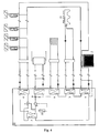
- modules (11) comprising: refrigerant compressor (1), condenser (3), two-stage evaporator with integrated liquid subcooler / suction steam superheater (4/5), injection valve (2), refrigerant, auxiliary refrigerants (9), frequency converter ( Fig. 4 ; 10), cables and electrical controls.
- a significant increase in performance is achieved by connecting one or more subcooling stages ( Fig. 2 ; 6) to the integrated subcooler (5).
Landscapes
- Engineering & Computer Science (AREA)
- Physics & Mathematics (AREA)
- Mechanical Engineering (AREA)
- Thermal Sciences (AREA)
- General Engineering & Computer Science (AREA)
- Air Conditioning Control Device (AREA)
- Devices That Are Associated With Refrigeration Equipment (AREA)
- Other Air-Conditioning Systems (AREA)
Abstract
Description
Kühl- und Tiefkühlanlagen, Kältetechnik, Kältemaschine für Kühl- und Heizbetrieb, Kälteanlagen, Kältesätze, Wärmepumpen, Energierückgewinnung, Abwärmenutzung: Modultechnik, welche zum Kühlen und / oder Heizen von diversen Medien wie Flüssigkeiten, Luft, Gasen oder anderen Energieträgem verwendet wird.Refrigeration and freezing systems, refrigeration technology, chiller for cooling and heating operation, refrigeration systems, refrigeration sets, heat pumps, energy recovery, waste heat recovery: modular technology, which is used for cooling and / or heating of various media such as liquids, air, gases or other energy sources.
Frequenzgesteuerte Kältemittelverdichter, Kältesätze, Unterkühlung, Energiespeicherung sind einzeln, aber nicht in der Kombination, wie hier vorgestellt, bekannt und kennen in dieser Kombination auch den Einsatz des neu erfundenen und hier auch zum Patent angemeldeten Zweistufenverdampfers mit integrierter Flüssigkeitsunterkühlung und Saugdampfüberhitzung nicht.Frequency-controlled refrigerant compressors, refrigeration units, supercooling, energy storage are individually, but not in the combination, as presented here known and know in this combination, the use of the newly invented and here also pending registered two-stage evaporator with integrated liquid supercooling and Saugdampfüberhitzung not.
Stand der Technik sind auch Anlagen mit einstufiger Unterkühlung, Saugdampfüberhitzung, Direktverdampfungsanlagen für Kältemittel, Wärmeträger-Kühlanlagen (Sekundärkühler), Kaskadenkühlanlagen, Boosterkühlanlagen, Kühlanlagen mit Trockenexpansion (trockener Verdampfer), Thermosyphonsysteme (überflutete Verdampfer) und Kältesätze.State of the art are also systems with single-stage subcooling, Saugdampfüberhitzung, Direktverdampfungsanlagen for refrigerants, heat transfer refrigeration systems (secondary cooler), cascade refrigeration, Boosterkühlanlagen, cooling systems with dry expansion (dry evaporator), Thermosyphonsysteme (flooded evaporator) and Kältesätze.
Der Einsatz von frequenzgesteuerten Kältemittelverdichtem, modularem Aufbau von Kältesätzen, Unterkühlung und Energiespeicherung dienen bis heute nicht dafür, dass man so kleine Kältemittelverdichter, wie hier vorgestellt, einsetzen und damit sehr hohe Leistungsspitzen eines geforderten Kältebedarfs direkt über die erzeugte mechanische Kälteleistung abdecken kann.The use of frequency-controlled refrigerant compressors, modular design of refrigeration sets, supercooling and energy storage are still not used to use such small refrigerant compressors as presented here and thus can cover very high power peaks of a required refrigeration demand directly on the generated mechanical refrigeration capacity.
Aus der Druckschrift
Nur die Kombination von Zweistufenverdampfung mit integrierter Flüssigkeitsunterkühlung und Saugdampfüberhitzung (4/5) in frequenzgesteuerter Modultechnik (10/11) mit mehrstufiger Unterkühlung (6) gemäss den Ansprüchen 1-11 garantiert die Erreichung der nachfolgenden Ziele.Only the combination of two-stage evaporation with integrated liquid subcooling and Saugdampfüberhitzung (4/5) in frequency-controlled module technology (10/11) with multi-stage supercooling (6) according to claims 1-11 guarantees the achievement of the following objectives.
Ziel der Erfindung ist es, bei Kühl-/Triefkühlanlagen, Kältemaschinen für Kühl- und Heizbetrieb, Kälteanlagen, Kältesätzen, Wärmepumpen und allen Anlagen mit Einsatz von Kältemittel und Kälteträgern folgendes zu erreichen: Tiefer Energieverbrauch, hohe Betriebssicherheit, hohe Verfügbarkeit der Kälte, geringe Servicekosten, schnelle Reaktionszeit (bis der Schaden behoben ist, egal welcher Art der Schaden ist), einfache Anlagentechnik, einfacher Systemausbau, günstige Investitionskosten, Schutz der Investition, grosse Unabhängigkeit (von Produkten, Kältemittel, etc.).The aim of the invention is, in cooling / Triefkühlanlagen, chillers for cooling and heating operation, refrigeration systems, chillers, heat pumps and all systems with the use of refrigerants and refrigerants to achieve the following: Deep energy consumption, high reliability, high availability of cold, low service costs , fast reaction time (until the damage is repaired, whatever the nature of the damage), simple plant technology, simple system development, low investment costs, protection of investment, great independence (of products, refrigerants, etc.).
Die COP-Werte und die Betriebssicherheit drastisch zu erhöhen, die Unterhalts-, Betriebs- und Investitionskosten drastisch zu senken, die Möglichkeit, sehr kleine Kältemittelverdichter (1) im Verhältnis zur maximal abzuführenden Kälteleistung einzusetzen, über den grössten Zeitraum eines Standard-Kühlungsprozesses mit sehr hohen Wirkungsgraden und sehr kleinen Kältemittelverdichterleistungen die Kälteleistung zu erzeugen und dabei sehr hohe Kälteleistungsspitzen abzudecken (Verhältnis von Minimalbedarf zum Durchschnittsbedarf und Maximalbedarf an Kälteleistung über einen kurzen oder langen Zeitraum betrachtet).To dramatically increase COP levels and operational reliability, drastically reduce maintenance, operating and investment costs, the ability to use very small refrigerant compressors (1) in proportion to the maximum refrigeration capacity to be dissipated over the largest period of a standard refrigeration process high efficiencies and very small refrigerant compressor outputs to produce the cooling capacity and thereby cover very high cooling power peaks (ratio of minimum demand to average demand and maximum demand for refrigeration over a short or long period considered).
Im weiteren sind obige Ziele mit sehr wenig einzusetzenden Komponenten (9) und kältetechnischen Hilfsstoffen sowie einem Minimum an benötigtem Kältemittel zu erreichen.Furthermore, the above goals with very little to be used components (9) and refrigerants auxiliaries and a minimum of required refrigerant can be achieved.
Die Kälteenergie zu Zeiten zu erzeugen und zu speichern (12), in denen wenig Kälteenergie benötigt wird (27).To generate and store the cold energy at times (12) in which little Cold energy is needed (27).
Diese Energie (27) zur Abdeckung von Kälteleistungsspitzen zu verwenden und dadurch einen gleichmässigeren Energieaufwand und -bedarf und gleichmässigere Betriebszustände (längere Laufzeiten mit weniger EIN/AUS-Zyklen der Verdichter) zu erhaltenTo use this energy (27) to cover peak refrigeration peaks and thereby obtain more even energy consumption and consumption and more consistent operating conditions (longer run times with less compressor ON / OFF cycles)
Die Erfindung beruht auf der Kombination und Weiterentwicklung obiger Systeme in modular aufgebauten Kälteanlagen (11) (Kältesätzen).The invention is based on the combination and further development of the above systems in modular refrigeration systems (11) (refrigeration sets).
Unter Modultechnik (11) (Kältesätze) verstehen wir eine anschlussfertige Kälteanlage pro Modul (11) (Kältesatz) wobei die Module (11) parallel miteinander zu einem Kältesystem verbunden werden.By module technology (11) (refrigeration sets) we mean a ready-to-connect refrigeration system per module (11) (refrigeration unit) whereby the modules (11) are connected in parallel with each other to form a refrigeration system.
Verschiedene Leistungsgrössen von Modulen (11) werden eingesetzt und es können mehrere Module (11) an ein Kältesystem angeschlossen werden.Various power ratings of modules (11) are used and several modules (11) can be connected to a refrigeration system.
Je nach Bedarf kann für ein System mit einem oder mehreren Modulen (11) begonnen und dieses später durch weitere Module (11) ausgebaut werden.Depending on requirements, a system may be started with one or more modules (11) and later removed by further modules (11).
Es können mehrere Systeme miteinander kombiniert werden und die einzelnen Module (11) sind transportabel und anschlussfertig.Several systems can be combined and the individual modules (11) are portable and ready for connection.
Durch den Einsatz der Frequenzregelung (10) und der Parallelschaltung der Module (11) können für heute übliche Prozesse, mit wesentlich kleineren Kältemittelverdichtern (1), Spitzenlasten abgedeckt werden.By using the frequency control (10) and the parallel connection of the modules (11) can be covered for today's common processes, with much smaller refrigerant compressors (1), peak loads.
Die Kältemittelverdichterleistung wird durch den Einsatz eines speziellen, zweistufigen Verdampfers mit integrierter Flüssigkeitsunterkühlung und Saugdampfüberhitzung (4 / 5) wesentlich gesteigert.Refrigerant compressor performance is significantly enhanced by the use of a special two-stage evaporator with integrated liquid subcooling and superheated steam overheating (4/5).
Infolge der Modultechnik (11) erhöht sich die Verfügbarkeit der maschinell erzeugten Kälte wesentlich gegenüber üblicher Einzel- oder Verbundanlagen.As a result of the module technology (11), the availability of machine-generated refrigeration increases significantly compared to conventional individual or combined systems.
Beim Ausfall eines Kältemoduls (11) wird die fehlende Kälteleistung über die Drehzahlerhöhung der anderen Kältemittelverdichter (Frequenzregelung) (10) teilweise oder ganz kompensiert.In the event of failure of a refrigeration module (11), the missing refrigeration capacity is partially or completely compensated for via the speed increase of the other refrigerant compressors (frequency control) (10).
Durch den Einsatz der speziellen Zweistufenverdampfertechnik mit integriertem Flüssigkeitsunterkühler / Saugdampfüberhitzer (4 / 5) und einer Zwei- oder Mehrstufenunterkühlung (6) ist es uns möglich, einen Teil der geforderten Kälteleistung in der Zeit zu erzeugen und zu speichern (12 / 27), in der wenig Kältebedarf herrscht und in der Zeit von grossem Kältebedarf zur Deckung dieser Spitzenlasten für die Leistungssteigerung durch die externe Unterkühlungsstufe (6 / 27) bereit zu stellen, ohne dass eine tiefere Verdampfungstemperatur (31) während der Speicherung nötig ist.By using the special two-stage evaporator technology with integrated liquid subcooler / suction steam superheater (4/5) and a two- or multi-stage subcooling (6), we are able to generate and store part of the required cooling capacity in time (12/27), in the low cooling demand prevails and in the time of high refrigeration demand to cover these peak loads for the performance increase by the external subcooling stage (6/27) without the need for a lower evaporation temperature (31) during storage.
Die gespeicherte Kälteenergie (12/27) dient dabei zur Flüssigkeitsunterkühlung des Kältemittels (externe Unterkühlung) (6/27).The stored cooling energy (12/27) is used for liquid subcooling of the refrigerant (external supercooling) (6/27).
Andere Energiequellen können ebenfalls zur Kältemittelunterkühlung (6) herangezogen werden.Other energy sources can also be used for refrigerant subcooling (6).
Eine weitere Stufe der Flüssigkeitsunterkühlung des Kältemittels wird mittels Verdampfung des Kältemittels und Saugdampf der Kälteanlage (interne Unterkühlung) (5) realisiert.Another stage of the liquid subcooling of the refrigerant is realized by means of evaporation of the refrigerant and suction steam of the refrigeration system (internal subcooling) (5).
Die Erfindung dieses Verdampfungsprozesses mit Flüssigkeitsunterkühlung und Saugdampfüberhitzung (4 / 5) begründet sich auf folgendem:The invention of this evaporation process with liquid supercooling and suction steam superheating (4/5) is based on the following:
Bekannt sind Trockenexpansionssysteme (trockener Verdampfer) mit Einspritzventil, bei dem ein überhitztes und gasförmiges Kältemittel den Verdampfer verlässt (20).Dry expansion systems (dry evaporator) with injection valve are known in which an overheated and gaseous refrigerant leaves the evaporator (20).
Bekannt sind Thermosyphonsysteme (überfluteter Verdampfer), bei denen flüssiges Kältemittel in den Verdampfer geführt wird und überhitztes, gasförmiges oder nicht überhitztes und mit Flüssigkeitsanteilen versehenes Kältemittel in einen Abscheider strömt und von dort gasförmig und ohne Flüssigkeitsanteile zum Kältemittelverdichter geführt wird.Thermosyphone systems are known (flooded evaporator), in which liquid refrigerant is fed into the evaporator and superheated, gaseous or not superheated and provided with liquid components refrigerant flows into a separator and is guided from there in gaseous form and without liquid components to the refrigerant compressor.
Bekannt sind Kältesysteme, bei denen ein Wärmeaustausch zwischen gasförmigem und flüssigem Kältemittel zur Unterkühlung der Flüssigkeit und zur Überhitzung des Saugdampfes realisiert wird (Flüssigkeits-Saugdampf-Wärmetauscher).Are known refrigeration systems in which a heat exchange between gaseous and liquid refrigerant for supercooling of the liquid and for overheating of the suction steam is realized (liquid-suction steam heat exchanger).
Bekannt sind Kombinationen mit Abwärmenutzung und Kaskaden-KälteanlagenAre known combinations with waste heat recovery and cascade refrigeration systems
Neu an unserer Erfindung ist, dass ein Verdampfungssystem mit Trockenexpansion als überfluteter Verdampfer (4) eingesetzt wird, bei dem das Kältemittel den Verdampfer in der ersten Stufe mit Flüssigkeitsanteilen verlässt (21).What is new about our invention is that a dry expansion evaporation system is used as the flooded evaporator (4) in which the refrigerant leaves the evaporator in the first stage with liquid fractions (21).
Neu an unserer Erfindung ist, dass das Kältemittel als Flüssigkeits-/Gasgemisch mit hohem Gasanteil in eine zweite Verdampfungsstufe (5/21) eintritt (trockener Verdampfer), bei der eine Restverdampfung mit anschliessend hoher Überhitzung des Kältemittels (22) und einer gleichzeitigen Unterkühlung des flüssigen Kältemittels auf der zweiten Seite des Wärmetauschers stattfindet (23).New to our invention is that the refrigerant enters as a liquid / gas mixture with a high gas content in a second evaporation stage (5/21) (dry evaporator), in which a residual evaporation followed by high superheating of the refrigerant (22) and a simultaneous supercooling of the liquid refrigerant takes place on the second side of the heat exchanger (23).
Neu an unserer Erfindung ist, dass das verwendete, ausserhalb oder innerhalb des Verdampfers eingebaute Expansionsventil (2) die Grösse der Saugdampftemperatur am Eintritt des Kältemittelverdichters (1/22) beschränkt und zugleich die Leistung der internen Unterkühlung (5 / 23) in Abhängigkeit der zur Verfügung stehenden Verdampferleistung (5/24) der ersten Stufe (4 / 25) regelt.What is new about our invention is that the expansion valve (2) used outside or inside the evaporator restricts the size of the suction steam temperature at the inlet of the refrigerant compressor (1/22) and at the same time reduces the power of the internal subcooling (5/23) Available evaporator capacity (5/24) of the first stage (4/25) controls.
Neu an unserer Erfindung ist im weiteren auch das Zusammenwirken all dieser Komponenten wie Modulbauweise (11) (Kältesatz), Frequenzregelung der Kältemittelverdichter (10), Parallelschaltung der Kältemittelverdichterkreisläufe, Zweistufenverdampfung mit interner Flüssigkeitsunterkühlung und Saugdampfüberhitzung (4/5), Zwei- oder Mehrstufenunterkühlung (5/6), Verlagerung und Speicherung der Kälteenergie von Zeiten mit wenig Bedarf nach Zeiten mit hohem Bedarf (12 / 27), integrierte Abwärmenutzung (7 / 8), wobei durch die interne Unterkühlung (5/23) höhere Temperaturen zur Abwärmenutzung (7/8/26) zur Verfügung stehen.
Kombinationen aller Art von Abwärmenutzung, Kaskaden- und Notbetrieb auf Modul-, Anlagen- oder Systemebene sind möglich.New to our invention is also the interaction of all these components such as modular construction (11) (refrigeration charge), frequency control of the refrigerant compressor (10), parallel circuit of the refrigerant compressor circuits, two-stage evaporation with internal liquid supercooling and Saugdampfüberhitzung (4/5), two- or Mehrstufenunterkühlung ( 5/6), relocation and storage of the refrigeration energy of times with little need for times of high demand (12/27), integrated waste heat utilization (7/8), whereby due to the internal supercooling (5/23) higher temperatures for waste heat utilization (7/8) / 8/26).
Combinations of all types of waste heat utilization, cascade and emergency operation at module, system or system level are possible.
Anforderung an die Modultechnik (11) ist höchste Betriebssicherheit, tiefe Betriebskosten, tiefe Unterhaltskosten, einfache Anlagentechnik, einfache Leistungsanpassung an benötigte Kälteleistung (Ausbauetappen) und einfache und flexible Anpassung an mögliche Abwärmenutzungen (7 / 8).Requirement for the module technology (11) is maximum operational safety, low operating costs, low maintenance costs, simple system technology, simple performance adjustment to required cooling capacity (expansion stages) and simple and flexible adaptation to possible waste heat utilization (7/8).
Energieeinsparung auf 3 Ebenen ist durch mehrstufige Unterkühlung (5 / 6), durch Leistungsverschiebung (zum Beispiel vom Tag in die Nacht (12 / 27) und durch Frequenzregelung (10) realisiert was alles tiefe Betriebskosten zur Folge hat.Energy saving on 3 levels is achieved by multilevel supercooling (5/6), by power shifting (for example, from day to night (12/27) and frequency control (10) which results in low operating costs.
Zusätzliche Optimierungen der Betriebskosten werden erreicht durch tiefere Verflüssigungstemperaturen in der Nacht, durch höhere Verdampfungstemperaturen (Kaltsoletemperaturanhebung), durch höhere Gasaustrittstemperaturen (Abwärmenutzung (7/8/26)), durch bessere Wirkungsgrade (überdimensionierte Anlagen arbeiten im Teillastbereich nicht optimal).Additional optimization of the operating costs are achieved by lower condensing temperatures at night, by higher evaporation temperatures (cold oil temperature increase), by higher gas outlet temperatures (waste heat utilization (7/8/26)), by better efficiencies (oversized systems do not work optimally in the partial load range).
Weiteren Betriebskostenoptimierungen sind die zu vernachlässigenden Druckabfälle in den Leitungen, eine mögliche, teilweise Stromverlagerung (vom Tag in die Nacht) (12 / 27) welche nicht zu Lasten einer tieferen Verdampfungstemperatur (31) geht, eine gleichmässige Laufzeit der Kältemittelverdichter (1) - wenige Ein- / Aus-Zyklen welche zusätzlich unterstützt wird durch die Erzeugung der Unterkühlerleistung (6 / 27) während der Nacht (angestrebt wird ein Dauerbetrieb der Kältemittelverdichter (1) - abhängig vom Prozess), weniger und reduzierter Anlaufstrom durch weniger Ein- / Aus-Zyklen, Frequenzumformer (10) und kleinere Kältemittelverdichter (1), sowie hohe COP-Werte (Verhältnis elektrische Energie zu Kälteenergie).Further operating cost optimizations are the negligible pressure drops in the pipes, a possible, partial current transfer (from day to night) (12/27) which does not affect a lower evaporation temperature (31), a uniform running time of the refrigerant compressor (1) - a few On / off cycles which are additionally supported by the generation of the subcooler power (6/27) during the night (continuous operation of the refrigerant compressors (1) is aimed for - depending on the process), less and reduced starting current due to less on / off Cycles, frequency converters (10) and smaller refrigerant compressors (1), as well as high COP values (ratio of electrical energy to refrigeration energy).
Ausfall nur eines Teils des Systems. Die restlichen Module (11) übernehmen einen Teil der fehlenden Kälteleistung bei Ausfall eines Moduls über die Frequenzumformung (10).Failure of only part of the system. The remaining modules (11) take over part of the missing cooling capacity in case of failure of a module via the frequency conversion (10).
Schnelle Reaktionszeit bei Ausfall eines Anlageteils da das Wechseln des ganzen Moduls (11) und die Reparatur in der Werkstatt gemacht werden kann.Fast reaction time in case of failure of a part of the system as the whole module (11) can be changed and repaired in the workshop.
Einfache Anlagentechnik (11) da keine Spezialisten notwendig sind.Simple system technology (11) as no specialists are necessary.
Hohe Verfügbarkeit infolge mehrerer Module (11) (Kältesätze).High availability due to several modules (11) (refrigeration rates).
Bei einem Ausfall des Eisspeichers (12 / 27) ist eine Notkühlung für die Unterkühlung (6 / 27) z.B. über das Netzwasser realisiert.In case of failure of the ice storage (12/27), emergency cooling for subcooling (6/27) e.g. realized via the mains water.
Bei einem Ausfall der Rückkühler (13) ist eine Notkühlung für die Verflüssiger (3) z.B. über das Netzwasser realisiert.In case of failure of the recooler (13) is an emergency cooling for the condenser (3), for. realized via the mains water.
Extrem kleine Kältemittelverdichter (1), um eine geforderte Kälteleistungsspitze abzudecken vereinfachen die Kälteanlagetechnik bedeutend.Extremely small refrigerant compressors (1) to cover a required peak cooling capacity simplify the refrigeration system significantly.
Dazu kommen die Vorteile von kleineren Rückkühlern (13), keine Öl- und Kältemittelverlagerungen sind möglich, weniger Öl- und Kältemittelinhalt, weniger kältetechnische Apparaturen (9), mehr Gleichzeitigkeit bei der Abwärmenutzung (7 / 8), einer Integration von Tiefkühlanlagen die jederzeit möglich ist (Kaskadenbetrieb), Notkreisläufe (Unterkühlung (6 / 27) / Kondensation (3)) welche ausserhalb der Kältekreisläufe realisiert werden, Saugdampftemperaturen am Kältemittelverdichtereintritt (1/22) und Flüssigkeitsschläge welche unter Kontrolle sind.In addition, there are the advantages of smaller recoolers (13), no oil and refrigerant displacements are possible, less oil and refrigerant content, less refrigeration equipment (9), more simultaneous waste heat utilization (7/8), an integration of freezers at any time is (cascade operation), emergency circuits (subcooling (6/27) / condensation (3)) which are realized outside the refrigeration circuits, suction steam temperatures at the refrigerant compressor inlet (1/22) and liquid blows which are under control.
Kleine Systemeinheiten (11) (Kältesatz) haben kleine Komponenten (9/1/2/etc.) und somit tiefe Komponentenpreise, kurze Stillstandzeiten und eine hohe Verfügbarkeit solcher Komponenten.Small system units (11) (refrigeration kit) have small components (9/1/2 / etc.) And thus low component prices, short downtime and high availability of such components.
Bei Ausfall eines Moduls (11) übernehmen die andern Module (11) einen Teil der fehlenden Kälteleistung über die Frequenzumformung (10).In case of failure of a module (11), the other modules (11) take over part of the missing cooling capacity via the frequency conversion (10).
Kurze Reaktionszeiten zum Beheben einer Störung da standardisierte Module (11) Lagerware sind.Short reaction times to correct a fault because standardized modules (11) are in stock.
Längere Lebensdauer der Kältemittelverdichter (1) durch weniger Ein- / Aus-Zyklen.Longer life of the refrigerant compressor (1) due to fewer on / off cycles.
Eine Grundversorgung kann nach Bedarf erweitert werden sofern die Infrastruktur (Leitungen, etc.) auf Endausbaugrösse installiert ist.A basic supply can be extended as required as long as the infrastructure (lines, etc.) is installed to its final size.
Ein problemloser Standortwechsel der Anlagen ist in Folge der Transportierbarkeit der Module (11) (Kältesätze) gegeben.An easy change of location of the systems is given as a result of the transportability of the modules (11) (refrigeration sets).
Die Produkteunabhängigkeit ist dadurch gegeben, dass Module mit unterschiedlichen Komponenten (Kältemittel, Kältemittelverdichter (1), Wärmeaustauscher (3/4/5/6/7/8), etc.) gebaut werden können.The product independence is due to the fact that modules with different components (refrigerant, refrigerant compressor (1), heat exchangers (3/4/5/6/7/8), etc.) can be built.
Vorschriften betreffend Druck, Kältemittel, Füllmengen, etc. sind mit kleinen, in Werkstätten hergestellten Einheiten (11) einfacher und günstiger zu erfüllen.Regulations concerning pressure, refrigerant, quantities, etc. are easier and cheaper to fulfill with small workshop-produced units (11).
Einfache Anlagentechnik (11) und dass keine Spezialisten notwendig sind, sind weitere Investitionsvorteile.Simple system technology (11) and no specialists are necessary are further investment advantages.
- Betriebssicherheitoperational safety
- EnergieeinsparungEnergy saving
- Kosteneinsparungcost saving
-
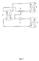
Fig. 1 : Minimale mögliche Lösung mit zwei unabhängigen Wärmeaustauschern (4 / 5)Fig. 1 : Minimum Possible Solution with Two Independent Heat Exchangers (4/5) -
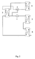
Fig. 2 : Minimale mögliche Lösung mit Zweistufenunterkühlung (6 / 5)Fig. 2 : Minimum possible solution with two-stage supercooling (6/5) -
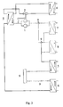
Fig. 3 : Mögliche zusätzliche Komponenten pro Modul (7/8/9, nicht abschliessend)Fig. 3 : Possible additional components per module (7/8/9, not final) -
Fig. 4 : Mögliche Systemeinbindung (eine mögliche Variante, nicht abschliessend)Fig. 4 : Possible system integration (one possible variant, not final) -
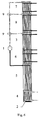
Fig. 5 : Neue Entwicklung eines Kombi-Plattenwärmeaustauschers (3/4/5/6/7/8) als Zweistufenverdampfer (4 / 5) mit integrierter Flüssigkeitsunterkühlung (5) und Saugdampfüberhitzung (5), Verflüssiger/Enthitzer (7), Verflüsger/ Enthitzer (8), Verflüssiger/Rückkühler (3)und Unterkühler erste Stufe (6) und mit externem oder internem Einspritzventil (2).Fig. 5 : Development of a combi plate heat exchanger (3/4/5/6/7/8) as a two-stage evaporator (4/5) with integrated liquid subcooling (5) and superheated steam superheating (5), condenser / desuperheater (7), condenser / desuperheater (5) 8), condenser / recooler (3) and subcooler first stage (6) and with external or internal injector (2). -
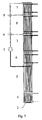
Fig. 6 : Neue Entwicklung eines Kombi-Plattenwärmeaustauschers (3/4/5/6/7/8) als Zweistufenverdampfer (4 / 5) mit integrierter Flüssigkeitsunterkühlung (5) und Saugdampfüberhitzung (5), Verflüssiger/Enthitzer (7), Verflüssiger/ Enthitzer (8), Verflüssiger/Rückkühler (3)und Unterkühler erste Stufe (6) und mit internem Einspritzventil (2) in anderer Bauweise.Fig. 6 : Development of a combi plate heat exchanger (3/4/5/6/7/8) as a two-stage evaporator (4/5) with integrated liquid subcooling (5) and superheated steam superheating (5), condenser / desuperheater (7), condenser / desuperheater (5) 8), condenser / recooler (3) and subcooler first stage (6) and with internal injection valve (2) in a different design. -
Fig. 7 : Neue Entwicklung eines Kombi-Plattenwärmeaustauschers (3/4/5/6/7/8) als Zweistufenverdampfer (4 / 5) mit integrierter Flüssigkeitsunterkühlung (5) und Saugdampfüberhitzung (5), Verflüssiger/Enthitzer (7), Verflüssiger/ Enthitzer (8), Verflüssiger/Rückkühler (3)und Unterkühler erste Stufe (6) und mit internem Einspritzventil (2) in anderer Bauweise.Fig. 7 : Development of a combi plate heat exchanger (3/4/5/6/7/8) as a two-stage evaporator (4/5) with integrated liquid subcooling (5) and superheated steam superheating (5), condenser / desuperheater (7), condenser / desuperheater (5) 8), condenser / recooler (3) and subcooler first stage (6) and with internal injection valve (2) in a different design. -
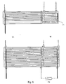
Fig. 8 : Neue Entwicklung eines Zweistufenplattenverdampfers (4 / 5) mit integrierter Flüssigkeitsunterkühlung (5) und Saugdampfüberhitzung (5) mit externem oder internem Einspritzventil (2).Fig. 8 : New development of a two-stage plate evaporator (4/5) with integrated liquid subcooling (5) and suction steam superheating (5) with external or internal injection valve (2). -
Fig. 9 : Neue Entwicklung eines Zweistufenplattenverdampfers (4/5) mit integrierter Flüssigkeitsunterkühlung (5) und Saugdampfüberhitzung (5) mit externem oder internem Einspritzventil (2) in anderer Bauweise.Fig. 9 : New development of a two-stage plate evaporator (4/5) with integrated liquid subcooling (5) and suction steam superheating (5) with external or internal injection valve (2) in a different design. -
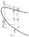
Fig. 10 : Diagramm mit der Darstellung der physikalischen VerhältnisseFig. 10 : Diagram showing the physical conditions -
Fig. 11 : Legende und Beschreibung zu den Zeichnungen und Werten in (..)Fig. 11 : Legend and description of the drawings and values in (..) -
Fig. 12 : Legende und Beschreibung zu den Zeichnungen und Werten in (..)Fig. 12 : Legend and description of the drawings and values in (..)
Ein Kältemodul (Kältesatz) (11) besteht im Wesentlichen aus einem oder mehreren:
- Verflüssigern (3), Flüssigkeitsunterkühlern (6), Flüssigkeitsunterkühlern/ Saugdampfüberhitzer-Verdampfern (5) (trockener Verdampfer zweite Stufe), Verdampfern (4) (überfluteter Verdampfer, erste Stufe), Kältemittelverdichtern (1), Einspritzventilen (2), Frequenzumformer (10), Kältemittel, kältetechnischen Hilfsstoffen und Öl (9).
- Condensers (3), liquid subcoolers (6), liquid subcoolers / steam superheater evaporators (5) (second stage dry evaporator), evaporators (4) (flooded evaporator, first stage), refrigerant compressors (1), injectors (2), frequency converters (10 ), Refrigerants, refrigerants and oil (9).
Optional weist ein Modul (11) (Kältesatz) zusätzlich einen oder mehrere Enthitzer (7 / 8), einen oder mehrere Abwärmenutzungstauscher (7 / 8), weitere Unterkühler, Schaugläser (9), Trockner (9), Filter, Ventile, Sicherheitsapparaturen, Absperrapparaturen, Sammler (9), Ölpumpen, Verteilsysteme (9), Elektro-, Steuer- und Regelteile (9), kältetechnische Hilfsstoffe, etc. auf.Optionally, a module (11) (refrigeration kit) additionally comprises one or more desuperheaters (7/8), one or more waste heat utilization exchangers (7/8), further sub-coolers, sight glasses (9), dryers (9), filters, valves, safety equipment, Absperrapparaturen, collectors (9), oil pumps, distribution systems (9), electrical and control parts (9), refrigeration aids, etc. on.
Die Wärmeaustauscher (3/4/5/6/7/8) können als einzelne Komponenten verrohrt oder als Kombitauscher konstruiert eingesetzt werden.The heat exchangers (3/4/5/6/7/8) can be cased as individual components or used as a combined exchanger.
Das Einspritzventil (2) wird vor dem Verdampfer (4) oder im Verdampfer (4 / 5) (erste Verdampfungsstufe) montiert.The injection valve (2) is mounted in front of the evaporator (4) or in the evaporator (4/5) (first evaporation stage).
Bei der Montage des Einspritzventils (2) vor dem Verdampfer (4) wird der Messwert zur Saugdampfbegrenzung an der Saugleitung zum Kältemittelverdichter (1/22) abgenommen. Alternativ stehen die Messwerte der unterkühlten Flüssigkeit (28), des Hochdrucks vor dem Einspritzventil (2 / 29) und des Saugdampfdrucks nach dem Einspritzventil (2 / 30) ebenfalls zur Regelung des Zweistufen-Verdampfers mit integriertem Flüssigkeitsunterkühler / Saugdampfüberhitzung (4 / 5) zur Verfügung.When installing the injection valve (2) before the evaporator (4), the measured value for Saugdampfbegrenzung on the suction line to the refrigerant compressor (1/22) is removed. Alternatively, the measured values of the supercooled liquid (28), the high pressure upstream of the injection valve (2/29) and the suction vapor pressure downstream of the injection valve (2/30) are also used to control the two-stage evaporator with integrated liquid subcooler / suction steam superheat (4/5) available.
Im Minimum reichen folgende Komponenten (gem. Zeichnung
Eine deutliche Leistungssteigerung wird durch das Vorschalten einer oder mehrerer Unterkühlungsstufen (
Alle weiteren Kombinationen von Komponenten (Zeichnung
Claims (11)
- Refrigeration plant of modular design having one or more modules or refrigeration sets (11) arranged in parallel, characterized in that each module (11) comprises at least one refrigerant compressor (1), which can be controlled by means of a frequency converter (10), a liquefier (3), a two-stage evaporator with integrated liquid supercooler/ suction vapour supercooler in the form of an internal heat exchanger in the second evaporation stage (4, 5), an injection valve (2) and lines, auxiliary refrigeration substances (9) and a refrigerant filling, the refrigerant leaving the first evaporation stage, designed as a flooded evaporator, with liquid fractions and entering the second evaporation stage, designed as a dry evaporator, as a liquid/gas mixture with a high gas fraction, in which second stage residual evaporation with subsequent high superheating of the refrigerant and simultaneous supercooling of the liquid refrigerant takes place on the second side of the internal heat exchanger.
- Refrigeration plant according to Claim 1, characterized in that the supercooler (6) is connected upstream of the two-stage evaporator with integrated liquid supercooler and suction vapour superheater (4, 5).
- Refrigeration plant according to Claim 1 or 2, characterized in that one or more desuperheaters/ liquefiers (7, 8) for waste heat utilization are connected downstream of the refrigerant compressor (1).
- Refrigeration plant according to one of Claims 1-3, characterized in that a number of modules (11) are assembled in parallel to form a refrigeration system.
- Refrigeration plant according to Claim 2, characterized in that the external supercooler (6) can be connected up and disconnected in dependence on the demand for refrigeration.
- Refrigeration plant according to Claim 2 or 5, characterized in that the external supercooler (6) is connected to a refrigeration store (12) for temporary storage of the refrigeration energy.
- Refrigeration plant according to Claim 2 or 5, characterized in that the refrigeration energy for the external supercooler (6) originates from independent sources, such as for example groundwater.
- Method for operating a refrigeration plant according to Claim 1, characterized in that an evaporation system with dry expansion is used as the flooded evaporator (4), in which the refrigerant leaves the evaporator in the first stage with liquid fractions (21) and the refrigerant enters a second evaporation stage (5/21), operating as a dry evaporator, as a liquid/gas mixture with a high gas fraction, in which second stage a residual evaporation with subsequent high superheating of the refrigerant (22) and simultaneous supercooling of the liquid refrigerant takes place on the second side of the internal heat exchanger (23).
- Method according to Claim 8, characterized in that the level of the suction vapour pressure at the inlet of the refrigerant compressor (1/22) is limited and at the same time the power of the internal supercooling (5/23) is controlled in dependence on the available evaporator power (5/24) of the first stage (4/25).
- Method according to Claim 9, characterized in that the measured value for limiting the suction vapour is taken at the suction line leading to the refrigerant compressor.
- Method according to Claim 9, characterized in that the measured values for the supercooled liquid (28), the high pressure upstream of the injection valve (2/29) and the suction vapour pressure downstream of the injection valve (2/30) are used for controlling the two-stage evaporator.
Applications Claiming Priority (1)
| Application Number | Priority Date | Filing Date | Title |
|---|---|---|---|
| PCT/CH2002/000470 WO2004020918A1 (en) | 2002-08-28 | 2002-08-28 | Two-stage evaporation system comprising an integrated liquid supercooler and a suction vapour superheater according to frequency-controlled module technology |
Publications (3)
| Publication Number | Publication Date |
|---|---|
| EP1537367A1 EP1537367A1 (en) | 2005-06-08 |
| EP1537367B1 true EP1537367B1 (en) | 2011-11-30 |
| EP1537367B8 EP1537367B8 (en) | 2012-03-14 |
Family
ID=31954516
Family Applications (1)
| Application Number | Title | Priority Date | Filing Date |
|---|---|---|---|
| EP02754098A Expired - Lifetime EP1537367B8 (en) | 2002-08-28 | 2002-08-28 | Two-stage evaporation system comprising an integrated liquid supercooler and a suction vapour superheater according to frequency-controlled module technology |
Country Status (8)
| Country | Link |
|---|---|
| US (1) | US7257965B2 (en) |
| EP (1) | EP1537367B8 (en) |
| AT (2) | ATE535765T1 (en) |
| AU (1) | AU2002322958A1 (en) |
| DE (1) | DE10297770D2 (en) |
| DK (1) | DK1537367T3 (en) |
| ES (1) | ES2377393T3 (en) |
| WO (1) | WO2004020918A1 (en) |
Families Citing this family (19)
| Publication number | Priority date | Publication date | Assignee | Title |
|---|---|---|---|---|
| US6505475B1 (en) | 1999-08-20 | 2003-01-14 | Hudson Technologies Inc. | Method and apparatus for measuring and improving efficiency in refrigeration systems |
| FR2906604A1 (en) * | 2006-09-28 | 2008-04-04 | Heliotrans Sarl | MODULE USEFUL FOR STORAGE AND THERMAL TRANSFER. |
| WO2009065233A1 (en) * | 2007-11-21 | 2009-05-28 | Remo Meister | System for refrigeration, heating or air-conditioning technology, particularly refrigeration systems |
| DE202008002015U1 (en) | 2008-01-31 | 2008-05-29 | Meister, Remo | Modular air conditioning system |
| JP2009257708A (en) * | 2008-04-21 | 2009-11-05 | Daikin Ind Ltd | Heat exchanger unit |
| DE102008043823B4 (en) * | 2008-11-18 | 2011-05-12 | WESKA Kälteanlagen GmbH | heat pump system |
| FR2945478B1 (en) * | 2009-05-13 | 2015-07-17 | Valeo Systemes Thermiques | VENTILATION, HEATING AND / OR AIR CONDITIONING INSTALLATION COMPRISING FOUR HEAT EXCHANGERS |
| JP5404333B2 (en) * | 2009-11-13 | 2014-01-29 | 三菱重工業株式会社 | Heat source system |
| CH704990A1 (en) | 2011-05-20 | 2012-11-30 | Remo Meister | A method of repairing or checking a accommodated in a pressure-tight closed container, in particular refrigeration system and container for carrying out the method. |
| EP2728277B1 (en) * | 2011-06-29 | 2020-03-04 | Mitsubishi Electric Corporation | Air-conditioning device |
| ITMI20111933A1 (en) * | 2011-10-25 | 2013-04-26 | Climaveneta S P A | THERMO FRIGORIFIA UNIT AND METHOD FOR ITS CONTROL |
| CN102679546A (en) * | 2012-05-24 | 2012-09-19 | 广州市设计院 | Efficient high-temperature hot-water heat pump unit |
| DE102012023823A1 (en) * | 2012-12-05 | 2014-06-05 | Daimler Ag | Vehicle air conditioning |
| US9146045B2 (en) | 2013-08-07 | 2015-09-29 | Climacool Corp | Modular chiller system comprising interconnected flooded heat exchangers |
| CN103604234B (en) * | 2013-11-14 | 2016-01-27 | 芜湖凯博尔高科实业有限公司 | A kind of cooling device of alternative cooling tower |
| US9476613B2 (en) * | 2014-04-10 | 2016-10-25 | Mahle International Gmbh | Method to control a cooling circuit |
| DE102015209848A1 (en) * | 2015-05-28 | 2016-12-01 | Efficient Energy Gmbh | Heat pump with entangled evaporator / condenser arrangement and evaporator bottom |
| US10655895B2 (en) * | 2017-05-04 | 2020-05-19 | Weiss Technik North America, Inc. | Climatic test chamber with stable cascading direct expansion refrigeration system |
| CN112361684B (en) * | 2020-11-30 | 2021-09-07 | 珠海格力电器股份有限公司 | Control method and device for two-stage variable frequency compression refrigeration system and air conditioning unit |
Family Cites Families (10)
| Publication number | Priority date | Publication date | Assignee | Title |
|---|---|---|---|---|
| IT1186300B (en) * | 1985-05-03 | 1987-11-18 | Bruno Bernardi | MODULAR UNIT FOR COLD OR HOT TREATMENT OF FLUIDS IN GENERAL |
| US5092138A (en) * | 1990-07-10 | 1992-03-03 | The University Of Maryland | Refrigeration system |
| US5243837A (en) | 1992-03-06 | 1993-09-14 | The University Of Maryland | Subcooling system for refrigeration cycle |
| DE19719256B4 (en) * | 1997-05-07 | 2005-08-18 | Valeo Klimatechnik Gmbh & Co. Kg | More than twin-tube flat tube heat exchanger for motor vehicles with deflection floor and manufacturing process |
| DE19719254B4 (en) * | 1997-05-07 | 2005-08-18 | Valeo Klimatechnik Gmbh & Co. Kg | Collector of a heat exchanger for motor vehicles with chamber division of intersecting flat bars |
| DE29800048U1 (en) * | 1998-01-03 | 1998-04-23 | Koenig Harald | Heat pump with arrangement of a heat exchanger to improve the coefficient of performance |
| DE19805285A1 (en) * | 1998-02-10 | 1999-08-12 | Behr Gmbh & Co | Evaporator unit for air-conditioning plant |
| US6220337B1 (en) * | 1998-04-27 | 2001-04-24 | Shi-Li Chen | Heat pipe circuit type thermal battery |
| US6185946B1 (en) * | 1999-05-07 | 2001-02-13 | Thomas B. Hartman | System for sequencing chillers in a loop cooling plant and other systems that employ all variable-speed units |
| US6263964B1 (en) * | 1999-11-12 | 2001-07-24 | Cheng-Fu Yang | Heat exchanging apparatus of refrigeration system |
-
2002
- 2002-08-28 US US10/525,165 patent/US7257965B2/en not_active Expired - Lifetime
- 2002-08-28 WO PCT/CH2002/000470 patent/WO2004020918A1/en not_active Application Discontinuation
- 2002-08-28 DK DK02754098.8T patent/DK1537367T3/en active
- 2002-08-28 EP EP02754098A patent/EP1537367B8/en not_active Expired - Lifetime
- 2002-08-28 ES ES02754098T patent/ES2377393T3/en not_active Expired - Lifetime
- 2002-08-28 AU AU2002322958A patent/AU2002322958A1/en not_active Abandoned
- 2002-08-28 DE DE10297770T patent/DE10297770D2/en not_active Ceased
- 2002-08-28 AT AT02754098T patent/ATE535765T1/en active
- 2002-08-28 AT AT0930802A patent/AT503557B1/en not_active IP Right Cessation
Also Published As
| Publication number | Publication date |
|---|---|
| ATE535765T1 (en) | 2011-12-15 |
| DK1537367T3 (en) | 2012-03-26 |
| US7257965B2 (en) | 2007-08-21 |
| ES2377393T3 (en) | 2012-03-27 |
| AT503557B1 (en) | 2007-11-15 |
| AT503557A5 (en) | 2007-11-15 |
| US20060090506A1 (en) | 2006-05-04 |
| EP1537367A1 (en) | 2005-06-08 |
| DE10297770D2 (en) | 2005-09-29 |
| AU2002322958A1 (en) | 2004-03-19 |
| EP1537367B8 (en) | 2012-03-14 |
| WO2004020918A1 (en) | 2004-03-11 |
Similar Documents
| Publication | Publication Date | Title |
|---|---|---|
| EP1537367B1 (en) | Two-stage evaporation system comprising an integrated liquid supercooler and a suction vapour superheater according to frequency-controlled module technology | |
| US6519967B1 (en) | Arrangement for cascade refrigeration system | |
| EP1895246B3 (en) | Refrigeration circuit and method for operating a refrigeration circuit | |
| CN101592412B (en) | Adjustable multi-temperature refrigeration device | |
| EP2226594A1 (en) | Refrigeration device | |
| WO2006015741A1 (en) | Refrigeration circuit and method for operating a refrigeration circuit | |
| GB2446062A (en) | Carbon dioxide refrigeration system with compressors in two-stage arrangement | |
| EP2610470A2 (en) | Method for operating a stationary power plant with at least one combustion engine | |
| CN111174453B (en) | Refrigerating system | |
| CN110173913A (en) | A kind of steam compressed high temperature heat pump unit of very large super cooling degree | |
| DE102005049950B4 (en) | Method for generating low temperatures and a cascade refrigeration system operating thereafter | |
| CN201449080U (en) | Multi-temperature refrigerating plant using single compressor | |
| CN109386980A (en) | A kind of cold and hot energy utility system | |
| EP3673215A1 (en) | Operating method for a cooling and/or heating system, and cooling and/or heating system | |
| EP2215412A1 (en) | System for refrigeration, heating or air-conditioning technology, particularly refrigeration systems | |
| CN110411047A (en) | Refrigeration system | |
| EP2199671A1 (en) | Method and device for producing water vapour | |
| CN205403270U (en) | Heat transfer device suitable for pressure refrigerant | |
| US7665321B2 (en) | Evaporation process control used in refrigeration | |
| EP2187149A2 (en) | Heat pump assembly | |
| CN115111808B (en) | Compression injection type dual-temperature heat pump system | |
| CN212987695U (en) | Flash-type refrigerating system using ejector | |
| EP2610445A2 (en) | Method for operating a stationary power plant with at least one combustion engine | |
| CN211400352U (en) | Dry-type open-type screw rod brine unit | |
| CN214276314U (en) | Auto-cascade refrigeration system of freeze dryer |
Legal Events
| Date | Code | Title | Description |
|---|---|---|---|
| PUAI | Public reference made under article 153(3) epc to a published international application that has entered the european phase |
Free format text: ORIGINAL CODE: 0009012 |
|
| 17P | Request for examination filed |
Effective date: 20050204 |
|
| AK | Designated contracting states |
Kind code of ref document: A1 Designated state(s): AT BE BG CH CY CZ DE DK EE ES FI FR GB GR IE IT LI LU MC NL PT SE SK TR |
|
| AX | Request for extension of the european patent |
Extension state: AL LT LV MK RO SI |
|
| 17Q | First examination report despatched |
Effective date: 20060410 |
|
| GRAP | Despatch of communication of intention to grant a patent |
Free format text: ORIGINAL CODE: EPIDOSNIGR1 |
|
| GRAJ | Information related to disapproval of communication of intention to grant by the applicant or resumption of examination proceedings by the epo deleted |
Free format text: ORIGINAL CODE: EPIDOSDIGR1 |
|
| APBN | Date of receipt of notice of appeal recorded |
Free format text: ORIGINAL CODE: EPIDOSNNOA2E |
|
| RIN1 | Information on inventor provided before grant (corrected) |
Inventor name: MEISTER, REMO |
|
| APBR | Date of receipt of statement of grounds of appeal recorded |
Free format text: ORIGINAL CODE: EPIDOSNNOA3E |
|
| APAF | Appeal reference modified |
Free format text: ORIGINAL CODE: EPIDOSCREFNE |
|
| APBZ | Receipt of observations in appeal recorded |
Free format text: ORIGINAL CODE: EPIDOSNOBA4E |
|
| APBT | Appeal procedure closed |
Free format text: ORIGINAL CODE: EPIDOSNNOA9E |
|
| GRAP | Despatch of communication of intention to grant a patent |
Free format text: ORIGINAL CODE: EPIDOSNIGR1 |
|
| GRAS | Grant fee paid |
Free format text: ORIGINAL CODE: EPIDOSNIGR3 |
|
| GRAA | (expected) grant |
Free format text: ORIGINAL CODE: 0009210 |
|
| AK | Designated contracting states |
Kind code of ref document: B1 Designated state(s): AT BE BG CH CY CZ DE DK EE ES FI FR GB GR IE IT LI LU MC NL PT SE SK TR |
|
| AX | Request for extension of the european patent |
Extension state: AL LT LV MK RO SI |
|
| REG | Reference to a national code |
Ref country code: GB Ref legal event code: FG4D Free format text: NOT ENGLISH Ref country code: CH Ref legal event code: EP |
|
| REG | Reference to a national code |
Ref country code: CH Ref legal event code: NV Representative=s name: RENTSCH PARTNER AG |
|
| RAP2 | Party data changed (patent owner data changed or rights of a patent transferred) |
Owner name: MEISTER, REMO |
|
| REG | Reference to a national code |
Ref country code: IE Ref legal event code: FG4D Free format text: LANGUAGE OF EP DOCUMENT: GERMAN |
|
| RIN2 | Information on inventor provided after grant (corrected) |
Inventor name: MEISTER, REMO |
|
| REG | Reference to a national code |
Ref country code: DE Ref legal event code: R096 Ref document number: 50215303 Country of ref document: DE Effective date: 20120126 |
|
| REG | Reference to a national code |
Ref country code: SE Ref legal event code: TRGR |
|
| REG | Reference to a national code |
Ref country code: NL Ref legal event code: T3 |
|
| REG | Reference to a national code |
Ref country code: DK Ref legal event code: T3 |
|
| REG | Reference to a national code |
Ref country code: ES Ref legal event code: FG2A Ref document number: 2377393 Country of ref document: ES Kind code of ref document: T3 Effective date: 20120327 |
|
| LTLA | Lt: lapse of european patent or patent extension | ||
| PG25 | Lapsed in a contracting state [announced via postgrant information from national office to epo] |
Ref country code: GR Free format text: LAPSE BECAUSE OF FAILURE TO SUBMIT A TRANSLATION OF THE DESCRIPTION OR TO PAY THE FEE WITHIN THE PRESCRIBED TIME-LIMIT Effective date: 20120301 Ref country code: PT Free format text: LAPSE BECAUSE OF FAILURE TO SUBMIT A TRANSLATION OF THE DESCRIPTION OR TO PAY THE FEE WITHIN THE PRESCRIBED TIME-LIMIT Effective date: 20120330 |
|
| PG25 | Lapsed in a contracting state [announced via postgrant information from national office to epo] |
Ref country code: CY Free format text: LAPSE BECAUSE OF FAILURE TO SUBMIT A TRANSLATION OF THE DESCRIPTION OR TO PAY THE FEE WITHIN THE PRESCRIBED TIME-LIMIT Effective date: 20111130 |
|
| PG25 | Lapsed in a contracting state [announced via postgrant information from national office to epo] |
Ref country code: BG Free format text: LAPSE BECAUSE OF FAILURE TO SUBMIT A TRANSLATION OF THE DESCRIPTION OR TO PAY THE FEE WITHIN THE PRESCRIBED TIME-LIMIT Effective date: 20120229 Ref country code: CZ Free format text: LAPSE BECAUSE OF FAILURE TO SUBMIT A TRANSLATION OF THE DESCRIPTION OR TO PAY THE FEE WITHIN THE PRESCRIBED TIME-LIMIT Effective date: 20111130 Ref country code: EE Free format text: LAPSE BECAUSE OF FAILURE TO SUBMIT A TRANSLATION OF THE DESCRIPTION OR TO PAY THE FEE WITHIN THE PRESCRIBED TIME-LIMIT Effective date: 20111130 Ref country code: SK Free format text: LAPSE BECAUSE OF FAILURE TO SUBMIT A TRANSLATION OF THE DESCRIPTION OR TO PAY THE FEE WITHIN THE PRESCRIBED TIME-LIMIT Effective date: 20111130 |
|
| PLBE | No opposition filed within time limit |
Free format text: ORIGINAL CODE: 0009261 |
|
| STAA | Information on the status of an ep patent application or granted ep patent |
Free format text: STATUS: NO OPPOSITION FILED WITHIN TIME LIMIT |
|
| 26N | No opposition filed |
Effective date: 20120831 |
|
| REG | Reference to a national code |
Ref country code: DE Ref legal event code: R097 Ref document number: 50215303 Country of ref document: DE Effective date: 20120831 |
|
| BERE | Be: lapsed |
Owner name: MEISTER REMO Effective date: 20120831 |
|
| PG25 | Lapsed in a contracting state [announced via postgrant information from national office to epo] |
Ref country code: MC Free format text: LAPSE BECAUSE OF NON-PAYMENT OF DUE FEES Effective date: 20120831 |
|
| PG25 | Lapsed in a contracting state [announced via postgrant information from national office to epo] |
Ref country code: BE Free format text: LAPSE BECAUSE OF NON-PAYMENT OF DUE FEES Effective date: 20120831 |
|
| PG25 | Lapsed in a contracting state [announced via postgrant information from national office to epo] |
Ref country code: FI Free format text: LAPSE BECAUSE OF FAILURE TO SUBMIT A TRANSLATION OF THE DESCRIPTION OR TO PAY THE FEE WITHIN THE PRESCRIBED TIME-LIMIT Effective date: 20111130 |
|
| PGFP | Annual fee paid to national office [announced via postgrant information from national office to epo] |
Ref country code: DK Payment date: 20130821 Year of fee payment: 12 Ref country code: NL Payment date: 20130815 Year of fee payment: 12 Ref country code: IE Payment date: 20130829 Year of fee payment: 12 Ref country code: SE Payment date: 20130821 Year of fee payment: 12 Ref country code: AT Payment date: 20130813 Year of fee payment: 12 Ref country code: ES Payment date: 20130829 Year of fee payment: 12 |
|
| PGFP | Annual fee paid to national office [announced via postgrant information from national office to epo] |
Ref country code: FR Payment date: 20130823 Year of fee payment: 12 Ref country code: TR Payment date: 20130723 Year of fee payment: 12 Ref country code: GB Payment date: 20130821 Year of fee payment: 12 |
|
| PGFP | Annual fee paid to national office [announced via postgrant information from national office to epo] |
Ref country code: IT Payment date: 20130826 Year of fee payment: 12 |
|
| PG25 | Lapsed in a contracting state [announced via postgrant information from national office to epo] |
Ref country code: LU Free format text: LAPSE BECAUSE OF NON-PAYMENT OF DUE FEES Effective date: 20120828 |
|
| REG | Reference to a national code |
Ref country code: NL Ref legal event code: V1 Effective date: 20150301 |
|
| REG | Reference to a national code |
Ref country code: DK Ref legal event code: EBP Effective date: 20140831 |
|
| REG | Reference to a national code |
Ref country code: SE Ref legal event code: EUG |
|
| REG | Reference to a national code |
Ref country code: AT Ref legal event code: MM01 Ref document number: 535765 Country of ref document: AT Kind code of ref document: T Effective date: 20140828 |
|
| GBPC | Gb: european patent ceased through non-payment of renewal fee |
Effective date: 20140828 |
|
| PG25 | Lapsed in a contracting state [announced via postgrant information from national office to epo] |
Ref country code: IT Free format text: LAPSE BECAUSE OF NON-PAYMENT OF DUE FEES Effective date: 20140828 Ref country code: NL Free format text: LAPSE BECAUSE OF NON-PAYMENT OF DUE FEES Effective date: 20150301 |
|
| REG | Reference to a national code |
Ref country code: IE Ref legal event code: MM4A |
|
| PG25 | Lapsed in a contracting state [announced via postgrant information from national office to epo] |
Ref country code: AT Free format text: LAPSE BECAUSE OF NON-PAYMENT OF DUE FEES Effective date: 20140828 Ref country code: SE Free format text: LAPSE BECAUSE OF NON-PAYMENT OF DUE FEES Effective date: 20140829 |
|
| REG | Reference to a national code |
Ref country code: FR Ref legal event code: ST Effective date: 20150430 |
|
| PG25 | Lapsed in a contracting state [announced via postgrant information from national office to epo] |
Ref country code: GB Free format text: LAPSE BECAUSE OF NON-PAYMENT OF DUE FEES Effective date: 20140828 Ref country code: DK Free format text: LAPSE BECAUSE OF NON-PAYMENT OF DUE FEES Effective date: 20140831 |
|
| PG25 | Lapsed in a contracting state [announced via postgrant information from national office to epo] |
Ref country code: IE Free format text: LAPSE BECAUSE OF NON-PAYMENT OF DUE FEES Effective date: 20140828 Ref country code: FR Free format text: LAPSE BECAUSE OF NON-PAYMENT OF DUE FEES Effective date: 20140901 |
|
| PG25 | Lapsed in a contracting state [announced via postgrant information from national office to epo] |
Ref country code: ES Free format text: LAPSE BECAUSE OF NON-PAYMENT OF DUE FEES Effective date: 20140829 |
|
| PG25 | Lapsed in a contracting state [announced via postgrant information from national office to epo] |
Ref country code: TR Free format text: LAPSE BECAUSE OF NON-PAYMENT OF DUE FEES Effective date: 20140828 |
|
| REG | Reference to a national code |
Ref country code: CH Ref legal event code: PCAR Free format text: NEW ADDRESS: BELLERIVESTRASSE 203 POSTFACH, 8034 ZUERICH (CH) |
|
| PGFP | Annual fee paid to national office [announced via postgrant information from national office to epo] |
Ref country code: DE Payment date: 20210819 Year of fee payment: 20 Ref country code: CH Payment date: 20210819 Year of fee payment: 20 |
|
| REG | Reference to a national code |
Ref country code: DE Ref legal event code: R071 Ref document number: 50215303 Country of ref document: DE |
|
| REG | Reference to a national code |
Ref country code: CH Ref legal event code: PL |