EP1536288A2 - Spulenträgervorrichtung, Motor, diese verwendender Belichtungsapparat, und Verfahren zur Herstellung einer Vorrichtung - Google Patents
Spulenträgervorrichtung, Motor, diese verwendender Belichtungsapparat, und Verfahren zur Herstellung einer Vorrichtung Download PDFInfo
- Publication number
- EP1536288A2 EP1536288A2 EP04256775A EP04256775A EP1536288A2 EP 1536288 A2 EP1536288 A2 EP 1536288A2 EP 04256775 A EP04256775 A EP 04256775A EP 04256775 A EP04256775 A EP 04256775A EP 1536288 A2 EP1536288 A2 EP 1536288A2
- Authority
- EP
- European Patent Office
- Prior art keywords
- coil
- unit according
- supports
- spacer
- coils
- Prior art date
- Legal status (The legal status is an assumption and is not a legal conclusion. Google has not performed a legal analysis and makes no representation as to the accuracy of the status listed.)
- Withdrawn
Links
Images


Classifications
-
- G—PHYSICS
- G03—PHOTOGRAPHY; CINEMATOGRAPHY; ANALOGOUS TECHNIQUES USING WAVES OTHER THAN OPTICAL WAVES; ELECTROGRAPHY; HOLOGRAPHY
- G03F—PHOTOMECHANICAL PRODUCTION OF TEXTURED OR PATTERNED SURFACES, e.g. FOR PRINTING, FOR PROCESSING OF SEMICONDUCTOR DEVICES; MATERIALS THEREFOR; ORIGINALS THEREFOR; APPARATUS SPECIALLY ADAPTED THEREFOR
- G03F7/00—Photomechanical, e.g. photolithographic, production of textured or patterned surfaces, e.g. printing surfaces; Materials therefor, e.g. comprising photoresists; Apparatus specially adapted therefor
- G03F7/70—Microphotolithographic exposure; Apparatus therefor
- G03F7/70691—Handling of masks or workpieces
- G03F7/70758—Drive means, e.g. actuators, motors for long- or short-stroke modules or fine or coarse driving
-
- H—ELECTRICITY
- H02—GENERATION; CONVERSION OR DISTRIBUTION OF ELECTRIC POWER
- H02K—DYNAMO-ELECTRIC MACHINES
- H02K41/00—Propulsion systems in which a rigid body is moved along a path due to dynamo-electric interaction between the body and a magnetic field travelling along the path
- H02K41/02—Linear motors; Sectional motors
- H02K41/03—Synchronous motors; Motors moving step by step; Reluctance motors
-
- H—ELECTRICITY
- H02—GENERATION; CONVERSION OR DISTRIBUTION OF ELECTRIC POWER
- H02K—DYNAMO-ELECTRIC MACHINES
- H02K2201/00—Specific aspects not provided for in the other groups of this subclass relating to the magnetic circuits
- H02K2201/18—Machines moving with multiple degrees of freedom
Definitions
- the present invention relates to a coil support unit which supports a coil, more preferably, to a coil support unit in a linear or plane motor used in a stage device of a semiconductor exposure apparatus, and to a device manufacturing method using the above exposure apparatus.
- an exposure apparatus is used for transferring a pattern formed on a mask or reticle (to be generally called a "master” hereinafter) serving as a master, via a projection optical system, onto a wafer or glass plate (to be generally called a “substrate” hereinafter) serving as a substrate to which a resist or the like is applied.
- a mask or reticle to be generally called a "master” hereinafter
- a wafer or glass plate serving as a substrate to which a resist or the like is applied.
- a high-output linear motor is required along with an improvement in performance of the stage device.
- a heat amount is also greatly increased.
- a cooling capacity must be further increased. Also, it is important to increase the cooling capacity of the coil in order to prevent the increase in a coil resistance, and the damage to the coil wire caused by the increase in temperature of the coil.
- FIG. 12 An example of the conventional coil support unit in the linear motor is described in Japanese Patent Laid-Open No. 10-309071 (see Fig. 12).
- coils 1a, 1b, and 1c are partially and directly adhered and fixed to jackets 14 and 14' by epoxy resin or an adhesive, and then a coolant flows between the jackets.
- the coil is directly cooled to collect the generated heat, and the rate of increase in temperature of the coil decreases.
- the stage device which aligns the substrate by two-dimensionally driving, in a noncontact manner, the stage on which the substrate is mounted.
- a driving source of the stage device which drives the stage in a noncontact manner a plane motor has been known.
- the plane motor has a stage including a magnet portion serving as a movable portion which moves along X and Y directions, and a base serving as a fixed portion.
- the fixed portion of the plane motor has a plurality of coils stacked in, e.g., a Z direction. A current selectively flows to the coils of each layer to generate a force acting on the stage in a predetermined direction.
- the coil support unit which supports the coil by adhesion when a thermal expansion force is larger than an adhesion force, the coil may be separated by the thermal expansion force, and the positional accuracy of the coil may be deteriorated. Also, a coil coating may be peeled off, thereby causing a short circuit.
- a design limitation is imposed on an increase in adhesion area for increasing the adhesion force. For example, when a coolant directly cools the coil, the adhesion area of the coil must be minimum. Also, when a fixing means fixes the coil in all directions, the coil may locally deform by the thermal expansion force.
- An embodiment of the invention seeks to provide a coil support unit which supports a coil which generates a thrust to a movable portion such that stable thrust characteristics can be obtained, and a motor and exposure apparatus using the coil support unit.
- a coil support unit which supports, by a coil support portion, a coil for generating a thrust to a movable portion, is characterized in that the coil support portion constrains the coil in a thrust direction, and slidably supports the coil in a direction perpendicular to the thrust direction on a moving surface of the movable portion.
- the "coil support portion” is a portion where the coil or a spacer is attached.
- the coil support portion can include the wall surface of a cooling jacket for cooling a coil housing or the coil, and a rib, column, and the like which are fixed to the wall surfaces.
- the coil is a substantially elliptical coil
- the sliding direction is a major-axis direction of the coil.
- the "substantially elliptical coil” is a coil having a major-axis (long side) in one direction.
- the substantially elliptical coil includes a race track coil whose arc in the major-axis direction is linear, a rectangular coil, and a substantially rectangular coil which is rectangular without an acute angle.
- a force can be relieved in the major-axis direction of the coil where a large thermal expansion force is generated, and the possibility of local deformation of the coil can be reduced. Also, the coil is constrained and supported in the minor-axis direction where a small thermal expansion force is generated. Hence, the coil is prevented from shifting caused by the thrust, and the stable thrust characteristics can be obtained.
- the coil support portion detachably supports the coil.
- the coil support unit further comprises a spacer between the coil and the coil support portion, and the coil support portion slidably supports the spacer in the sliding direction. Since a fitting management between the spacer attached to the coil and the coil support portion is relaxed, the yield can increase.
- the coil is a substantially elliptical coil with a plurality of spacers
- the coil support portion includes a plurality of ribs juxtaposed in a major-axis direction. Since the fitting management between the plurality of spacers attached to the coils and the coil support portion is relaxed, the yield increase.
- the coil is constrained by a friction applied on a coil surface.
- the "coil surface” is an X-Y plane formed by coil windings.
- the coil surface includes a spacer surface. The coil can be constrained (aligned) in the thrust direction without abutting the coil or the spacer against the coil support portion. Hence, the fitting management between the coil or spacer and the coil support portion is remarkably relaxed.
- the coil support unit comprises preload force applying means for applying a preload force to the coil in a direction perpendicular to the coil surface.
- the coil can be constrained and slid by adjusting a friction by applying the preload force. Hence, the position of the coil can be easily adjusted.
- the friction is larger than the thrust, and is smaller than a thermal expansion force in the sliding direction of the coil.
- the coil support portion can support the coil by an anisotropic spring.
- the coil includes a spacer between the coil and the coil support portion, and the spacer includes the anisotropic spring.
- the coil can include a wedge portion, and the wedge portion can support the coil. Since the space between the coil and the spacer need not be fixed, for example, a time for adhesion between the coil and the spacer can be decreased.
- a protective material is provided between the coil and a sliding surface on which the coil slides.
- the "protective material” is a protective tape, a protective film, or the like. It suffices if the protective material can protect the coil coating not to be peeled off. This protective material can prevent the coil coating from being peeled off, and the coil from being damaged by a short circuit.
- the coil includes a multilayered coils stacked in a direction perpendicular to a moving surface.
- the coil support portion includes a rib, and the single rib supports the multilayered coils.
- the yield and space efficiency further increase.
- the single rib serves as a means for constraining the plurality of multilayered coils, thereby saving a space. When the coil is detachable, the yield can remarkably increase.
- the coil support unit further comprises preload force applying means for applying a preload force to the multilayered coils in a direction perpendicular to the moving surface, and the preload force applying means is arranged to the coil on the opposite side of the movable portion in a direction perpendicular to the moving surface. Since the multilayered coils can be supported with a short distance between the movable portion and the coil, the thrust efficiency increases.
- the coil support portion which supports the coil is integrated with a cooling jacket which cools the coil, and the coil is cooled in the cooling jacket.
- the heat of the coil can decrease, thereby ensuring the thrust and saving the space in the above-described coil support unit.
- the above-described coil support unit is preferably used in a linear or plane motor.
- an exposure apparatus drives, using these motors, a stage on which a substrate is mounted.
- the exposure apparatus preferably manufactures a device.
- a high-precision motor apparatus, a high-precision exposure apparatus, and a highly integrated device can be expected to be manufactured.
- Figs. 1A and 1B are views showing a plane motor according to the first embodiment of the present invention.
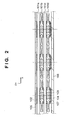
- Fig. 2 is a view showing a coil support unit in Fig. 1B. Since in Figs. 1A and 1B, a surface plate serving as a moving surface of a movable portion 10 is omitted for the sake of simplicity, a coil 101 is exposed. However, in an actual unit, the coil 101 is covered with the surface plate.
- the stage 10 serving as an object has a magnet portion 11, and can be driven in the X and Y directions by selectively flowing a current to the coil 101 on a base 13.
- the coil 101 includes substantially elliptical coils 101a with an elliptical (long side) portion in an X direction, and the plurality of substantially elliptical coils 101a are juxtaposed in a Y direction.
- the coil 101 includes substantially elliptical coils 101b with an elliptical portion in a Y direction, and the plurality of substantially elliptical coils 101b are juxtaposed in the X direction.
- the coil 101 includes the group of coils (101c, 101d) with an elliptical portion in a predetermined direction.
- the substantially elliptical coil 101b has the same shape as the substantially elliptical coil 101b, except for the major-axis direction.
- the substantially elliptical coil 101b has substantially plane portions (coil surfaces) on its upper and lower surfaces in a Z direction.
- a Lorentz force is applied, in the direction of a Y-Z plane, between the coil 101a and the magnet portion 11 arranged on the movable portion. Since a current flows in the elliptical portion of the substantially elliptical coil 101b in the Y direction, the Lorentz force is applied to the movable portion (magnet portion) in the direction of an X-Z plane.
- the long-side direction of the coil, the number of coils, the number of coil layers, and the like are arbitrarily designed in accordance with the object of the stage to be driven.
- the stage can be driven along six axes such as an X, Y, Z, ⁇ (a rotational direction about the Z-axis), ⁇ x (a rotational direction about the X-axis), and ⁇ y (a rotational direction about the Y-axis).
- the coil 101 is arranged in a cooling jacket (a space between a jacket ceiling plate 105 and a jacket wall 106), and a plurality of ribs 103 for supporting the coil are fixed to the cooling jacket.
- the plurality of ribs 103 are arranged on each of the coils in the major-axis direction as shown in Fig. 1A, and support the coil in the inner circumferential portion of the coil 101 via the spacer.
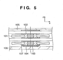
- Fig. 4A is an enlarged view of the coil support unit in Fig. 2.
- the coils 101 are attached to spacers 102, and the spacers 102 are stacked around the rib 103 in the Z direction.
- a coned disc spring 104 applies a preload force to the multilayered spacers 102 in the Z direction to constrain and support the spacers 102 to the jacket wall 106 and jacket ceiling plate 105.
- a stiction acts between the multilayered spacers 102, between the spacer 102 and the coned disc spring 104, and between the spacer 102 and the rib 103, by the preload force applied by the coned disc spring 104.
- the preload force is set such that the stiction becomes smaller than a thermal expansion force in the major-axis direction of the coil 101 (for example, the Y direction when the coil 101b is used).
- the spring constant of the coned disc spring 104 may be determined such that the preload force falls within the above-described range in assembling the coil support unit.
- the preload force may be adjusted by inserting a shim 107 with an optimal thickness between the coned disc spring 104 and the spacer 102.
- the coil can be prevented from local deformation by relieving the thermal expansion force in the direction which is not associated with a thrust (in the X direction when the coil 101b is used). Specifically, when the thermal expansion force is relieved in the major-axis direction of the elliptical coil, the effect can be further expected.
- the shim 107 also serves as a sliding surface with the spacer 102. That is, when using the shim 107, the stiction acts between the spacer 102 and the shim 107. Hence, the stiction can also be adjusted by changing the material of the shim 107. When this stiction is set to be smaller than the thermal expansion force in the major-axis direction of the coil, the coil can slide in only the major-axis direction, and the thermal expansion force of the coil 101 can be relieved.
- the coned disc spring 104 may be arranged in any position as long as the coned disc spring 104 applies the preload force to the spacer 102, and the preload force applying means need not be a coned disc spring.
- the preload force can be applied in a small space, and the coned disc spring can be obtained at low cost, because the coned disc spring has a simple structure. Since the coned disc spring is arranged at the portion opposite to the movable portion (not arranged between the coil and the magnet), the distance between the coil and the magnet can be made short.
- the spacer 102 is preferably made from a material which can resist a sliding operation for a long term.
- the material may include polyphenylene sulfide (PPS), polyetheretherketone (PEEK), polybutylene terephthalate (PBT), or fluoroplastic.
- PPS polyphenylene sulfide
- PEEK polyetheretherketone
- PBT polybutylene terephthalate
- fluoroplastic fluoroplastic
- the spacer 102 and the coil 101 can be fixed by any method as long as the stiction is larger than the thermal expansion force of the coil 101.
- the spacer 102 and the coil 101 can be fixed by adhesion. This is because since the large thermal expansion force applied to the coil 101 is relieved by sliding the spacer 102, a large stress does not act on the adhesion portion, and the possibility of the separation of the coil is low. Also, since the coil 101 is not adhered to the cooling jacket, it is easy to attach and remove the coil. Even when a problem occurs, the yield may increase since the coil can be easily replaced.
- a coolant whose temperature is managed flows into the space enclosed by the jacket wall 106 and the jacket ceiling plate 105. Hence, the heat of the coil 101 is exchanged, and the increase in temperature is prevented.
- the gap between the coil 101 and the magnet portion serving as the movable portion becomes wide, and a thrust constant is decreased. Therefore, a large current for generating the desired thrust is required, and the heat amount of the coil 101 increases. Therefore, the spacer 102 may have the optimal thickness for balance between a coolant channel and the thrust constant.
- Fig. 4B is a view of the rib seen from the Z direction.
- a hole is formed in the spacer 102, and the size of the hole is managed such that the two sides of the rib 103 abut against the spacer 102 in the X direction, and such that the two sides of the rib 103 are separated from the spacer 102 to be slidable in the Y direction.
- the columnar rib is arranged to easily attach the coil which is inserted into the spacer to each of the ribs juxtaposed in the Y direction.
- Fig. 5 shows an example in which the shape of the spacer attached to the coil is changed.
- a spacer 122 fixes the lower and side surfaces of the coil 101, and the coils 101 are juxtaposed around the rib 103 as in Fig 4A. Since the spacer has an L-shaped cross section, the spacer 122 is easily attached to the coil 101, and the assembly efficiency can increase. Since the upper end face of the spacer is set to be higher than the upper surface of the coil, the short circuit of the coil can be prevented, and the adhesion area in which the coil 101 contacts to the coolant can be ensured.
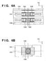
- Figs. 6A and 6B are views showing the second embodiment.
- Fig. 6A is an enlarged view of a coil support unit seen from a Y direction.
- Fig. 6B is a view of a coil having an elliptical portion in the Y direction (e.g., the coil on the second layer in Fig. 6A), seen from a Z direction.
- a spacer 102 does not abut against a rib 103 in the X direction and a major-axis direction (Y direction) of thrust directions.
- a shim 108 is arranged to abut against the rib in the X and Y directions.
- the spacer 102 can be constrained in the thrust direction.
- the preload force is set such that the stiction is larger than the thrust of the coil 101, and smaller than the thermal expansion force of the coil.
- the spring constant of the coned disc spring may be determined such that the preload force falls within the above-described range in assembling the coil support unit, or the preload force may be adjusted by adjusting the thickness of the shim 108.
- the coned disc spring may be arranged in any position as long as the coned disc spring applies the preload force to the spacer, and the means need not be a coned disc spring as long as the purpose is achieved.
- the shim 108 also serves as a sliding surface with the spacer 102.
- the coil 101 is constrained by the friction in the direction of a moving surface of the thrust directions, constrained by abutting in the Z direction of the thrust directions.
- the spacer 102 can slide since the thermal expansion force of the coil exceeds the friction in the major-axis direction, thereby relieving the thermal expansion force in the major-axis of the coil 101.
- the shim 108 is fixed in the X and Y directions, the coils on the respective layers do not interfere with each other by the thermal expansion forces of the coils. For example, when the thermal expansion force of the coil on the first layer is relieved in the X direction, the coil on the second layer is not interfered by the thermal expansion force in the X direction since the shim 108 is fixed.
- the coil can slide in the major-axis direction where the large thermal expansion force is generated without changing the thrust characteristics of the substantially elliptical coil.
- the coil support arrangement reliable for eliminating the damage to the coil can be obtained. Also, the assembly efficiency and the yield increase.
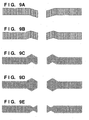
- Figs. 7A to 7E show the third embodiment.
- Fig. 7A is a view of a coil support unit seen from a Y direction.
- Figs. 7B to 7E are views of a coil having an elliptical portion in the Y direction (e.g., the coil on the second layer in Fig. 7A), seen from a Z direction.
- the detailed description of the similar arrangement to the first embodiment will be omitted.
- a coil can slide with a spacer in this embodiment while the spacer can slide in a major-axis direction in the first and second embodiments.
- a leaf spring 202' serving as an anisotropic spring is used to support a coil 201 to move the coil 201 only in one direction.
- the leaf spring 202' is integrated with a spacer 202 between the coil 201 and a rib 203 serving as a coil support portion.
- coned disc spring 204 applies a preload force to the spacer 202 in the Z direction to support the spacer 202 although the spacer 202 may be fixed to the rib 203.
- This preload force is used to suppress play caused by the dimensional error in the Z direction of the spacer 202, and to constrain and support the spacer 202.
- Any means can be used, e.g., a shim 207 with an optimal thickness can be inserted, as long as the above purpose is achieved.
- the coil 201 Since the anisotropic spring which is rigid in a thrust direction and flexible in the major-axis direction, the coil 201 can be rigidly constrained in the thrust direction, and moved in the major-axis direction by the leaf spring 202'. Hence, the thermal expansion force in the major-axis direction can be relieved.
- the arrangements of the coil 201 and the leaf spring 202' can be varied as long as the efficiency is not interfered. Some examples are described below.
- Fig. 7B since the position of the spacer is determined by abutting against the rib in X and Y directions, the slide of the spacer can be mechanically suppressed.
- the columnar rib is arranged to facilitate attaching the coils inserted into the spacers to the plurality of ribs which are juxtaposed in the Y direction.
- the leaf spring is fixed to the upper and lower surfaces of the coil to increase the constraint force applied to the coil in the Z direction.
- Fig. 7E a plurality of leaf springs support the coils to increase the constraint force applied to the coils in the Z direction.
- the coil is rigidly constrained in the thrust direction, and can move in the major-axis direction. Hence, the only thermal expansion force of the coil can be relieved.
- Figs. 8A to 8D show the fourth embodiment of the present invention.
- Fig. 8A is an enlarged view of a coil support unit seen from a Y direction.
- Fig. 8B is a view of a coil having an elliptical portion in the Y direction (e.g., the coil on the second layer in Fig. 8A), seen from a Z direction. The detailed description of the similar arrangement to the first embodiment will be omitted.
- the coil can slide with a spacer as in the third embodiment.
- the cross section of a coil 301 has a wedge shape in a winding direction (a Y direction in Fig. 8A) to geometrically constrain the coil.
- the cross sections of a group of multilayered substantially elliptical coils 301 juxtaposed in the X or Y direction have wedge shapes.
- the plurality of wedge portions are vertically sandwiched by spacers 302 in the Z direction, successively stacked to common ribs 303, receive the preload forces by a coned disc spring 304, and support the coils between a jacket wall 306 and a jacket ceiling plate 305.
- the space between the spacers 302 inserted into the coils is same as that between the common ribs 303.
- the positions of the vertically multilayered coils on the respective layers are defined by abutting the spacers of the coils.
- the coil 301 when applying the thrust to the coil, the coil 301 is constrained in the thrust direction by the effect of the wedge shape.
- the coil can slide to move.
- a protective tape 308 is adhered on the sliding portion of the coil 301 to prevent a short circuit which occurs, e.g., when an insulating film is peeled off by sliding the coil.
- assembly efficiency remarkably increases, and the coil support unit can be entirely disassembled and maintained after being assembled.
- the preload force applied by the coned disc spring 304 suppresses the play caused by the dimensional error in the Z direction of the spacer 302 to constrain and support the spacer 302.
- a friction is also small.
- the thermal expansion force of the coil can be efficiently relieved, and a large stress does not act on the coil 301 and the spacer 302.
- Figs. 9A to 9E show other examples of the cross sections of a wedge coil.
- Figs. 9A and 9B show examples of the wedge coils using flat wires.
- the cross section on the coil support member side (the inner circumferential side of the coil in this case) has a wedge shape.
- Figs. 9C, 9D, and 9E show examples of the cross sections of the wedge coils using round wires.
- the length of the cross section can be freely changed, unlike the flat wires, thereby implementing various wedge shapes. Note that even when the flat wires are used, the cross section can be same as that of the round wires by processing the wires.
- the wedge shape can be varied as long as the constraining and sliding directions of the coil can be defined. Also, a wedge-shaped guide may be attached to the flat coil afterwards.
- the above embodiment can be applied to the support of all coils. However, it is especially effective to support many coils as in the plane motor, or to support a long coil such as a substantially elliptical coil.
- a channel for flowing a coolant between the coils can be sufficiently ensured to efficiently cool the coils.
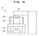
- Fig. 10 shows a semiconductor device manufacturing exposure apparatus which uses a stage apparatus similar to that described above as a wafer stage.
- This exposure apparatus is used for the manufacture of semiconductor devices such as a semiconductor integrated circuit, and devices such as a micromachine and thin-film magnetic head on which a fine pattern is formed.
- a semiconductor wafer W as a substrate is irradiated with exposure light (this term is a general term for visible light, ultraviolet light, EUV light, X-rays, an electron beam, a charged particle beam, and the like) as an exposure energy from a illumination system unit 501 through a reticle as a master via a projection lens 503 (this term is a general term for a dioptric lens, reflecting lens, cata-dioptric lens system, charged particle lens, and the like) as a projection system, to form a desired pattern on the substrate mounted on a wafer stage 504.
- exposure light this term is a general term for visible light, ultraviolet light, EUV light, X-rays, an electron beam, a charged particle beam, and the like
- a projection lens 503 this term is a general term for a dioptric
- the wafer (object) serving as the substrate is held on the chuck mounted on the wafer stage 504.
- the pattern of the reticle serving as the master mounted on a reticle stage 502 is transferred on each region on the wafer by a step-and-repeat or step-and-scan method by the illumination system unit 501.
- the stage device according to the first embodiment is used as the wafer stage 504 or the reticle stage 502.
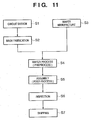
- Fig. 11 is a flow chart of an overall semiconductor device manufacturing process.
- step 1 circuit design
- step 2 mask fabrication
- a mask is fabricated based on the designed circuit pattern.
- step 3 wafer manufacture
- step 4 wafer process
- step 5 wafer process
- step 5 assembly
- step 6 inspections
- step 6 inspections
- a semiconductor device is completed with these processes, and is shipped in step 7.
- the wafer process of step 4 has the following steps: the oxidation step of oxidizing the surface of the wafer, the CVD step of forming an insulating film on the wafer surface, the electrode formation step of forming an electrode on the wafer by deposition, the ion implantation step of implanting ions into the wafer, the resist process step of applying a photosensitive agent to the wafer, the exposure step of transferring the circuit pattern to the wafer after the resist process step by the exposure apparatus described above, the developing step of developing the wafer exposed in the exposure step, the etching step of etching portions other than the resist image developed in the developing step, and the resist removing step of removing any unnecessary resist remaining after etching. By repeating these steps, a multilayered structure of circuit patterns is formed on the wafer.
Landscapes
- Physics & Mathematics (AREA)
- Engineering & Computer Science (AREA)
- General Physics & Mathematics (AREA)
- Chemical & Material Sciences (AREA)
- Combustion & Propulsion (AREA)
- Electromagnetism (AREA)
- Power Engineering (AREA)
- Exposure And Positioning Against Photoresist Photosensitive Materials (AREA)
- Linear Motors (AREA)
- Exposure Of Semiconductors, Excluding Electron Or Ion Beam Exposure (AREA)
- Motor Or Generator Cooling System (AREA)
Applications Claiming Priority (2)
| Application Number | Priority Date | Filing Date | Title |
|---|---|---|---|
| JP2003399884A JP4474151B2 (ja) | 2003-11-28 | 2003-11-28 | モータおよびそれを用いた露光装置ならびにデバイス製造方法 |
| JP2003399884 | 2003-11-28 |
Publications (2)
| Publication Number | Publication Date |
|---|---|
| EP1536288A2 true EP1536288A2 (de) | 2005-06-01 |
| EP1536288A3 EP1536288A3 (de) | 2006-06-14 |
Family
ID=34463890
Family Applications (1)
| Application Number | Title | Priority Date | Filing Date |
|---|---|---|---|
| EP04256775A Withdrawn EP1536288A3 (de) | 2003-11-28 | 2004-11-03 | Spulenträgervorrichtung, Motor, diese verwendender Belichtungsapparat, und Verfahren zur Herstellung einer Vorrichtung |
Country Status (3)
| Country | Link |
|---|---|
| US (2) | US7329972B2 (de) |
| EP (1) | EP1536288A3 (de) |
| JP (1) | JP4474151B2 (de) |
Families Citing this family (9)
| Publication number | Priority date | Publication date | Assignee | Title |
|---|---|---|---|---|
| JP4474151B2 (ja) * | 2003-11-28 | 2010-06-02 | キヤノン株式会社 | モータおよびそれを用いた露光装置ならびにデバイス製造方法 |
| US7956982B2 (en) * | 2005-11-18 | 2011-06-07 | Asml Netherlands B.V. | Apparatus for cooling |
| DE102006022192B4 (de) * | 2006-05-12 | 2009-08-27 | Rovema - Verpackungsmaschinen Gmbh | Vorrichtung zum Verschweißen einer Folienbahn |
| DE102006022193B4 (de) * | 2006-05-12 | 2009-08-27 | Rovema - Verpackungsmaschinen Gmbh | Vertikale Schlauchbeutelmaschine mit zwei Linearmotoren |
| JP5151568B2 (ja) * | 2008-03-10 | 2013-02-27 | 株式会社ニコン | ステージ装置及び露光装置 |
| US8885148B2 (en) * | 2011-01-04 | 2014-11-11 | Asml Holding N.V. | System and method for design of linear motor for vacuum environment |
| JP6074939B2 (ja) * | 2012-07-27 | 2017-02-08 | ソニー株式会社 | 発電機 |
| EP2733833B1 (de) * | 2012-11-15 | 2017-07-19 | Etel S. A.. | Primärteil eines eisenlosen Linearmotors |
| CN105830321B (zh) * | 2013-12-20 | 2019-04-09 | 株式会社富士 | 线性马达的推力常数导出方法、移动控制方法、线性马达的推力常数导出装置及移动控制装置 |
Family Cites Families (13)
| Publication number | Priority date | Publication date | Assignee | Title |
|---|---|---|---|---|
| JPH05304761A (ja) * | 1992-04-27 | 1993-11-16 | Mitsubishi Electric Corp | 超電導磁気浮上鉄道用地上コイル取付装置 |
| JPH07163127A (ja) | 1993-12-06 | 1995-06-23 | Hitachi Ltd | 磁気浮上式鉄道用地上コイル |
| JP3278380B2 (ja) | 1997-03-06 | 2002-04-30 | キヤノン株式会社 | リニアモータ |
| US6084319A (en) * | 1996-10-16 | 2000-07-04 | Canon Kabushiki Kaisha | Linear motor, and stage device and exposure apparatus provided with the same |
| JP3719016B2 (ja) | 1998-05-29 | 2005-11-24 | 日本精工株式会社 | リニアモータ |
| JP4088728B2 (ja) * | 1998-07-09 | 2008-05-21 | 株式会社ニコン | 平面モータ装置、駆動装置及び露光装置 |
| JP2001037200A (ja) * | 1999-07-19 | 2001-02-09 | Canon Inc | リニアモータ、ステージ装置、露光装置およびデバイス製造方法 |
| US6445093B1 (en) * | 2000-06-26 | 2002-09-03 | Nikon Corporation | Planar motor with linear coil arrays |
| JP2002034104A (ja) * | 2000-07-18 | 2002-01-31 | Mitsubishi Electric Corp | 地上敷設コイル装置 |
| JP2002176761A (ja) * | 2000-12-08 | 2002-06-21 | Canon Inc | リニアモータ及び該リニアモータを用いた露光装置 |
| JP3891545B2 (ja) * | 2001-07-10 | 2007-03-14 | キヤノン株式会社 | リニアモータ |
| JP2003274593A (ja) | 2002-03-18 | 2003-09-26 | Hitachi Ltd | 回転電機用固定子コイル |
| JP4474151B2 (ja) * | 2003-11-28 | 2010-06-02 | キヤノン株式会社 | モータおよびそれを用いた露光装置ならびにデバイス製造方法 |
-
2003
- 2003-11-28 JP JP2003399884A patent/JP4474151B2/ja not_active Expired - Fee Related
-
2004
- 2004-10-27 US US10/973,469 patent/US7329972B2/en not_active Expired - Fee Related
- 2004-11-03 EP EP04256775A patent/EP1536288A3/de not_active Withdrawn
-
2008
- 2008-01-23 US US12/018,299 patent/US7768156B2/en not_active Expired - Fee Related
Also Published As
| Publication number | Publication date |
|---|---|
| US7329972B2 (en) | 2008-02-12 |
| US7768156B2 (en) | 2010-08-03 |
| JP2005168089A (ja) | 2005-06-23 |
| US20080303354A1 (en) | 2008-12-11 |
| JP4474151B2 (ja) | 2010-06-02 |
| US20050116549A1 (en) | 2005-06-02 |
| EP1536288A3 (de) | 2006-06-14 |
Similar Documents
| Publication | Publication Date | Title |
|---|---|---|
| US7768156B2 (en) | Coil support unit, motor and exposure apparatus using the same, and device manufacturing method | |
| US6400516B1 (en) | Kinematic optical mounting | |
| US6323567B1 (en) | Circulating system for shaft-type linear motors | |
| US7282821B2 (en) | Linear motor, stage apparatus, exposure apparatus, and device manufacturing apparatus | |
| US7547998B2 (en) | Aligning apparatus including an attraction preventing plate provided between permanent magnet and magnetic member | |
| US7282874B2 (en) | Alignment apparatus, exposure apparatus, and device manufacturing method | |
| EP1107066B1 (de) | Lithographischer Apparat mit einer Maskenklemmvorrichtung | |
| US7057710B2 (en) | Stage system including fine-motion cable unit, exposure apparatus, and method of manufacturing device | |
| CN104769500B (zh) | 光刻设备和器件制造方法 | |
| US6313550B1 (en) | Coil mounting and cooling system for an electric motor | |
| US20010013580A1 (en) | Cooling of voice coil motors in lithographic projection apparatus | |
| US20030155882A1 (en) | Anti-gravity mount with air and magnets | |
| US20040245861A1 (en) | Linear motor, stage device having this linear motor, exposure device, and device manufacturing method | |
| US20040080727A1 (en) | EUV exposure apparatus with cooling device to prevent overheat of electromagnetic motor in vacuum | |
| US6639333B1 (en) | Linear motor stage system for use in exposure apparatus | |
| US6879127B2 (en) | 3-ring magnetic anti-gravity support | |
| JPH10309071A (ja) | リニアモータ及びこれを有するステージ装置や露光装置 | |
| EP1124160A2 (de) | Kühlung von linearen Schwingmotoren in lithographischen Projektionsapparaten | |
| JP2005295762A (ja) | ステージ装置および露光装置 | |
| JP2004281654A (ja) | 駆動機構及びそれを用いた露光装置、デバイスの製造方法 | |
| US7239051B2 (en) | Driving apparatus and exposure apparatus | |
| US6648509B2 (en) | Friction-drive stage | |
| US20060232145A1 (en) | System for cooling motors | |
| US7193683B2 (en) | Stage design for reflective optics | |
| JP4424733B2 (ja) | コイルユニット、電磁アクチュエータ、露光装置及びデバイス製造方法 |
Legal Events
| Date | Code | Title | Description |
|---|---|---|---|
| PUAI | Public reference made under article 153(3) epc to a published international application that has entered the european phase |
Free format text: ORIGINAL CODE: 0009012 |
|
| AK | Designated contracting states |
Kind code of ref document: A2 Designated state(s): AT BE BG CH CY CZ DE DK EE ES FI FR GB GR HU IE IS IT LI LU MC NL PL PT RO SE SI SK TR |
|
| AX | Request for extension of the european patent |
Extension state: AL HR LT LV MK YU |
|
| PUAL | Search report despatched |
Free format text: ORIGINAL CODE: 0009013 |
|
| AK | Designated contracting states |
Kind code of ref document: A3 Designated state(s): AT BE BG CH CY CZ DE DK EE ES FI FR GB GR HU IE IS IT LI LU MC NL PL PT RO SE SI SK TR |
|
| AX | Request for extension of the european patent |
Extension state: AL HR LT LV MK YU |
|
| 17P | Request for examination filed |
Effective date: 20061214 |
|
| AKX | Designation fees paid |
Designated state(s): DE GB NL |
|
| 17Q | First examination report despatched |
Effective date: 20110520 |
|
| STAA | Information on the status of an ep patent application or granted ep patent |
Free format text: STATUS: THE APPLICATION HAS BEEN WITHDRAWN |
|
| 18W | Application withdrawn |
Effective date: 20110117 |