EP1536182A1 - Steckdose für einen in einem Backofen angeordneten Temperaturfühler - Google Patents
Steckdose für einen in einem Backofen angeordneten Temperaturfühler Download PDFInfo
- Publication number
- EP1536182A1 EP1536182A1 EP04106035A EP04106035A EP1536182A1 EP 1536182 A1 EP1536182 A1 EP 1536182A1 EP 04106035 A EP04106035 A EP 04106035A EP 04106035 A EP04106035 A EP 04106035A EP 1536182 A1 EP1536182 A1 EP 1536182A1
- Authority
- EP
- European Patent Office
- Prior art keywords
- socket
- plug
- closure element
- oven
- spring
- Prior art date
- Legal status (The legal status is an assumption and is not a legal conclusion. Google has not performed a legal analysis and makes no representation as to the accuracy of the status listed.)
- Granted
Links
Images
Classifications
-
- F—MECHANICAL ENGINEERING; LIGHTING; HEATING; WEAPONS; BLASTING
- F24—HEATING; RANGES; VENTILATING
- F24C—DOMESTIC STOVES OR RANGES ; DETAILS OF DOMESTIC STOVES OR RANGES, OF GENERAL APPLICATION
- F24C7/00—Stoves or ranges heated by electric energy
- F24C7/08—Arrangement or mounting of control or safety devices
Definitions
- the invention relates to a socket for receiving a plug in the Cooking chamber of a baking oven arranged temperature sensor, wherein a Closing element for closing the socket after removal the plug is provided from the socket, and the Closing element when plugging the plug into the socket is pivotable.
- the invention has the object, a socket of the type mentioned to improve in the future so that they are easier and thus is cheaper in construction.
- the invention solves the task by a socket of the beginning mentioned type, which according to the invention is characterized in that the pivoted closure element has a contacting device, with the plugged in the temperature sensor with a Electrically connect transmitter.
- that fulfills Closure element in the future two functions. It closes the If this is not needed, and it fulfills the function of a power outlet Contact element.
- the required since then separate contact element omitted.
- the closure element locks the plugged in.
- locking the plug is secure in the Socket held, causing the electrical contact trouble-free is ensured. This is also the case if you accidentally turn on the cable pulls or wobbles.
- the closure element has a Contact pin which engages in a recess provided on the plug.
- the Locking and reliable electrical contact ensured.
- These Recess can be very reasonably priced by a circumferential groove in the area the plug end can be realized.
- the contact pin is also a constructive one simple and inexpensive component.
- the closure element To automatically close the socket when pulling out the Ensure plug from the power outlet, and for optimum Contact pressure for a reliable electrical contact at inserted plug, the closure element with be equipped a spring element.
- the closure element may have a Rubber plug for tightly closing the socket.
- This rubber stopper is advantageously made of a heat-resistant Rubber material made. As the rubber plug the socket tight closes, unwanted deposits are inaccessible Interior of the oven between the oven and a Oven case excluded.
- the Taper conically to its free end.
- the invention relates to a baking oven according to the invention with equipped at least one socket according to one of claims 1 to 8 is.
- the oven is a Steam oven.
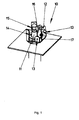
- the single figure shows a socket 10, in which a plug 11, with connected to a temperature sensor, not shown here, plugged can be.
- the socket 10 has a closure element 12.
- the Closure element 12 is pivotable via articulation points 13. If the Plug 11 is inserted into the socket 10, he pivots that Closure element 12 so that it releases an opening 14. If the Plug 11 is inserted far enough into the opening 14, he notes a contact pin, which can not be recognized here, on the closure element 12 is attached, make an electrical contact.
- the contact pin engages in one circumferential groove 15 on the plug 11 a.
- the closure element 12 also has a conical Rubber stopper 16 on, after pulling out the plug 11 from the socket 10 this safe and tight closes.
- a torsion spring 17 pushes the closure element 12 with the rubber stopper 16 in the Opening 14, and thus closes the socket 10 tight.
- presses the torsion spring 17, the closure element 12 with the not here recognizable contact pin against the plug 11, creating an electrical Contact between the contact pin and the plug 11 reliable will be produced.
Landscapes
- Engineering & Computer Science (AREA)
- Chemical & Material Sciences (AREA)
- Combustion & Propulsion (AREA)
- Mechanical Engineering (AREA)
- General Engineering & Computer Science (AREA)
- Details Of Connecting Devices For Male And Female Coupling (AREA)
- Connector Housings Or Holding Contact Members (AREA)
- Control Of High-Frequency Heating Circuits (AREA)
Abstract
Description
Claims (10)
- Steckdose (10) zur Aufnahme eines Steckers (11) eines im Garraum eines Backofens angeordneten Temperaturfühlers, mit einem Verschlusselement (12) zum Verschließen der Steckdose (10) nach dem Entfernen des Steckers (11) aus der Steckdose (10), welches Verschlusselement (12) beim Einstecken des Steckers (11) in die Steckdose (10) in eine Offenposition verstellt ist, dadurch gekennzeichnet, dass das Verschlusselement (12) eine Kontaktierungseinrichtung aufweist, die bei eingestecktem Stecker (11) den Temperaturfühler mit einer Auswerteelektronik elektrisch verbindet.
- Steckdose (10) nach Anspruch 1, dadurch gekennzeichnet, dass das Verschlusselement (12) eine Arretiereinrichtung zur Arretierung des eingesteckten Steckers (11) aufweist.
- Steckdose (10) nach Anspruch 2, dadurch gekennzeichnet, dass das Verschlusselement (12) einen Kontaktstift aufweist, der in eine am Stecker (11) vorgesehene Ausnehmung (15) eingreift.
- Steckdose (10) nach einem der Ansprüche 1 bis 3, dadurch gekennzeichnet, dass das Verschlusselement (12) mit einem Federelement (17) ausgerüstet ist.
- Steckdose (10) nach Anspruch 4, dadurch gekennzeichnet, dass das Federelement eine Torsionsfeder (17) ist.
- Steckdose (10) nach Anspruch 4, dadurch gekennzeichnet, dass das Federelement eine Gummifeder ist.
- Steckdose (10) nach einem der Ansprüche 1 bis 6, dadurch gekennzeichnet, dass das Verschlusselement (12) einen Gummipfropfen (16) zum dichten Verschließen der Steckdose (10) aufweist.
- Steckdose (10) nach Anspruch 7, dadurch gekennzeichnet, dass sich der Gummipfropfen (16) zu seinem freien Ende hin konisch verjüngt.
- Backofen, dadurch gekennzeichnet, dass er mindestens eine Steckdose (10) nach einem der Ansprüche 1 bis 8 aufweist.
- Backofen nach Anspruch 9, dadurch gekennzeichnet, dass er ein Dampfbackofen ist.
Priority Applications (1)
| Application Number | Priority Date | Filing Date | Title |
|---|---|---|---|
| EP04106035A EP1536182B1 (de) | 2003-11-26 | 2004-11-24 | Steckdose für einen in einem Backofen angeordneten Temperaturfühler |
Applications Claiming Priority (3)
| Application Number | Priority Date | Filing Date | Title |
|---|---|---|---|
| EP03360131 | 2003-11-26 | ||
| EP33601311 | 2003-11-26 | ||
| EP04106035A EP1536182B1 (de) | 2003-11-26 | 2004-11-24 | Steckdose für einen in einem Backofen angeordneten Temperaturfühler |
Publications (2)
| Publication Number | Publication Date |
|---|---|
| EP1536182A1 true EP1536182A1 (de) | 2005-06-01 |
| EP1536182B1 EP1536182B1 (de) | 2007-08-01 |
Family
ID=38336335
Family Applications (1)
| Application Number | Title | Priority Date | Filing Date |
|---|---|---|---|
| EP04106035A Expired - Lifetime EP1536182B1 (de) | 2003-11-26 | 2004-11-24 | Steckdose für einen in einem Backofen angeordneten Temperaturfühler |
Country Status (4)
| Country | Link |
|---|---|
| EP (1) | EP1536182B1 (de) |
| AT (1) | ATE368831T1 (de) |
| DE (1) | DE502004004499D1 (de) |
| ES (1) | ES2290631T3 (de) |
Cited By (2)
| Publication number | Priority date | Publication date | Assignee | Title |
|---|---|---|---|---|
| EP1950498A1 (de) * | 2007-01-23 | 2008-07-30 | Electrolux Home Products Corporation N.V. | Ofen |
| DE102015205489A1 (de) | 2015-03-26 | 2016-09-29 | BSH Hausgeräte GmbH | Haushaltsgerät |
Citations (3)
| Publication number | Priority date | Publication date | Assignee | Title |
|---|---|---|---|---|
| JPS5368451A (en) * | 1976-11-30 | 1978-06-17 | Sharp Corp | Electronic oven |
| FR2723268A1 (fr) * | 1994-07-28 | 1996-02-02 | Alcatel Cable Interface Sa | Connecteur femelle protege contre des pertubations, pour reseau de communication |
| EP1199528A2 (de) * | 2000-10-17 | 2002-04-24 | BSH Bosch und Siemens Hausgeräte GmbH | Steckdose für ein Bratenthermometer |
-
2004
- 2004-11-24 ES ES04106035T patent/ES2290631T3/es not_active Expired - Lifetime
- 2004-11-24 AT AT04106035T patent/ATE368831T1/de not_active IP Right Cessation
- 2004-11-24 DE DE502004004499T patent/DE502004004499D1/de not_active Expired - Lifetime
- 2004-11-24 EP EP04106035A patent/EP1536182B1/de not_active Expired - Lifetime
Patent Citations (3)
| Publication number | Priority date | Publication date | Assignee | Title |
|---|---|---|---|---|
| JPS5368451A (en) * | 1976-11-30 | 1978-06-17 | Sharp Corp | Electronic oven |
| FR2723268A1 (fr) * | 1994-07-28 | 1996-02-02 | Alcatel Cable Interface Sa | Connecteur femelle protege contre des pertubations, pour reseau de communication |
| EP1199528A2 (de) * | 2000-10-17 | 2002-04-24 | BSH Bosch und Siemens Hausgeräte GmbH | Steckdose für ein Bratenthermometer |
Non-Patent Citations (1)
| Title |
|---|
| PATENT ABSTRACTS OF JAPAN vol. 002, no. 098 (M - 030) 16 August 1978 (1978-08-16) * |
Cited By (2)
| Publication number | Priority date | Publication date | Assignee | Title |
|---|---|---|---|---|
| EP1950498A1 (de) * | 2007-01-23 | 2008-07-30 | Electrolux Home Products Corporation N.V. | Ofen |
| DE102015205489A1 (de) | 2015-03-26 | 2016-09-29 | BSH Hausgeräte GmbH | Haushaltsgerät |
Also Published As
| Publication number | Publication date |
|---|---|
| DE502004004499D1 (de) | 2007-09-13 |
| ATE368831T1 (de) | 2007-08-15 |
| ES2290631T3 (es) | 2008-02-16 |
| EP1536182B1 (de) | 2007-08-01 |
Similar Documents
| Publication | Publication Date | Title |
|---|---|---|
| DE3544180C2 (de) | ||
| DE102009020188B4 (de) | Vorrichtung zum Lösen eines in einem Gehäuse über eine Verbindung fixierten Transceivers aus dem Gehäuse | |
| DE60209902T2 (de) | Elektrischer steckverbinder | |
| DE102011016481B4 (de) | Verriegelungssystem für eine an einem Kraftfahrzeug, einer Ladestation oder einer Wand angeordnete Steckkuppeleinrichtung und Steckkuppeleinrichtung | |
| EP1943702B1 (de) | Reihenklemme | |
| WO2016062693A1 (de) | Elektrisches steckverbinderpaar | |
| DE10202407B4 (de) | Elektrische Steckverbindung mit Lösemechanismus | |
| DE102012100058B3 (de) | Gehäuse für ein Computersystem sowie Computersystem mit einem derartigen Gehäuse | |
| EP1536182B1 (de) | Steckdose für einen in einem Backofen angeordneten Temperaturfühler | |
| DE102015210410B3 (de) | Berührgeschützte Steckverbindung | |
| DE202013100297U1 (de) | Geräteanschlusssystem für Küchengeräte | |
| DE60038472T2 (de) | Steckverbinder mit Kabelzugentlastung | |
| EP2684257A2 (de) | Steckverbinder | |
| DE10255531B3 (de) | Stecker mit Schieber zum Verbinden mit einer Steckbuchse | |
| DE69519642T2 (de) | Elektrisches Steckergehäuse mit verbesserter Verriegelungsvorrichtung | |
| DE102014206734A1 (de) | Haushaltsgerät mit zumindest einer Bedienblende | |
| DE102011103345B3 (de) | Steckerbrücke für einen klappbaren 3-Pol-Stecker | |
| DE202011101451U1 (de) | Steckerbrücke für einen klappbaren 3-Pol-Stecker | |
| DE102010028802B4 (de) | Stecker mit einem Sperrelement | |
| DE102006029927A1 (de) | Winkelstecker | |
| DE10228131A1 (de) | Sicherheits-Steckvorrichtung für ein Abluftsystem | |
| EP1199528B1 (de) | Steckdose für ein Bratenthermometer | |
| DE102006024996B4 (de) | Elektrische Kupplung oder Steckdose mit Berührschutzelement | |
| DE60006470T2 (de) | Verbinder mit Verhinderung einer unvollständigen Kupplung | |
| DE19939408C1 (de) | Elektrischer Steckverbinder |
Legal Events
| Date | Code | Title | Description |
|---|---|---|---|
| PUAI | Public reference made under article 153(3) epc to a published international application that has entered the european phase |
Free format text: ORIGINAL CODE: 0009012 |
|
| AK | Designated contracting states |
Kind code of ref document: A1 Designated state(s): AT BE BG CH CY CZ DE DK EE ES FI FR GB GR HU IE IS IT LI LU MC NL PL PT RO SE SI SK TR |
|
| AX | Request for extension of the european patent |
Extension state: AL HR LT LV MK YU |
|
| 17P | Request for examination filed |
Effective date: 20051201 |
|
| AKX | Designation fees paid |
Designated state(s): AT BE BG CH CY CZ DE DK EE ES FI FR GB GR HU IE IS IT LI LU MC NL PL PT RO SE SI SK TR |
|
| GRAP | Despatch of communication of intention to grant a patent |
Free format text: ORIGINAL CODE: EPIDOSNIGR1 |
|
| GRAS | Grant fee paid |
Free format text: ORIGINAL CODE: EPIDOSNIGR3 |
|
| GRAA | (expected) grant |
Free format text: ORIGINAL CODE: 0009210 |
|
| AK | Designated contracting states |
Kind code of ref document: B1 Designated state(s): AT BE BG CH CY CZ DE DK EE ES FI FR GB GR HU IE IS IT LI LU MC NL PL PT RO SE SI SK TR |
|
| REG | Reference to a national code |
Ref country code: GB Ref legal event code: FG4D Free format text: NOT ENGLISH |
|
| REG | Reference to a national code |
Ref country code: CH Ref legal event code: EP |
|
| REG | Reference to a national code |
Ref country code: IE Ref legal event code: FG4D Free format text: LANGUAGE OF EP DOCUMENT: GERMAN |
|
| REF | Corresponds to: |
Ref document number: 502004004499 Country of ref document: DE Date of ref document: 20070913 Kind code of ref document: P |
|
| REG | Reference to a national code |
Ref country code: SE Ref legal event code: TRGR |
|
| ET | Fr: translation filed | ||
| GBT | Gb: translation of ep patent filed (gb section 77(6)(a)/1977) |
Effective date: 20071115 |
|
| PG25 | Lapsed in a contracting state [announced via postgrant information from national office to epo] |
Ref country code: NL Free format text: LAPSE BECAUSE OF FAILURE TO SUBMIT A TRANSLATION OF THE DESCRIPTION OR TO PAY THE FEE WITHIN THE PRESCRIBED TIME-LIMIT Effective date: 20070801 Ref country code: BG Free format text: LAPSE BECAUSE OF FAILURE TO SUBMIT A TRANSLATION OF THE DESCRIPTION OR TO PAY THE FEE WITHIN THE PRESCRIBED TIME-LIMIT Effective date: 20071101 Ref country code: FI Free format text: LAPSE BECAUSE OF FAILURE TO SUBMIT A TRANSLATION OF THE DESCRIPTION OR TO PAY THE FEE WITHIN THE PRESCRIBED TIME-LIMIT Effective date: 20070801 Ref country code: IS Free format text: LAPSE BECAUSE OF FAILURE TO SUBMIT A TRANSLATION OF THE DESCRIPTION OR TO PAY THE FEE WITHIN THE PRESCRIBED TIME-LIMIT Effective date: 20071201 |
|
| NLV1 | Nl: lapsed or annulled due to failure to fulfill the requirements of art. 29p and 29m of the patents act | ||
| REG | Reference to a national code |
Ref country code: ES Ref legal event code: FG2A Ref document number: 2290631 Country of ref document: ES Kind code of ref document: T3 |
|
| PG25 | Lapsed in a contracting state [announced via postgrant information from national office to epo] |
Ref country code: PL Free format text: LAPSE BECAUSE OF FAILURE TO SUBMIT A TRANSLATION OF THE DESCRIPTION OR TO PAY THE FEE WITHIN THE PRESCRIBED TIME-LIMIT Effective date: 20070801 |
|
| REG | Reference to a national code |
Ref country code: IE Ref legal event code: FD4D |
|
| PG25 | Lapsed in a contracting state [announced via postgrant information from national office to epo] |
Ref country code: GR Free format text: LAPSE BECAUSE OF FAILURE TO SUBMIT A TRANSLATION OF THE DESCRIPTION OR TO PAY THE FEE WITHIN THE PRESCRIBED TIME-LIMIT Effective date: 20071102 Ref country code: DK Free format text: LAPSE BECAUSE OF FAILURE TO SUBMIT A TRANSLATION OF THE DESCRIPTION OR TO PAY THE FEE WITHIN THE PRESCRIBED TIME-LIMIT Effective date: 20070801 |
|
| PG25 | Lapsed in a contracting state [announced via postgrant information from national office to epo] |
Ref country code: PT Free format text: LAPSE BECAUSE OF FAILURE TO SUBMIT A TRANSLATION OF THE DESCRIPTION OR TO PAY THE FEE WITHIN THE PRESCRIBED TIME-LIMIT Effective date: 20080102 Ref country code: CZ Free format text: LAPSE BECAUSE OF FAILURE TO SUBMIT A TRANSLATION OF THE DESCRIPTION OR TO PAY THE FEE WITHIN THE PRESCRIBED TIME-LIMIT Effective date: 20070801 Ref country code: SK Free format text: LAPSE BECAUSE OF FAILURE TO SUBMIT A TRANSLATION OF THE DESCRIPTION OR TO PAY THE FEE WITHIN THE PRESCRIBED TIME-LIMIT Effective date: 20070801 Ref country code: IE Free format text: LAPSE BECAUSE OF FAILURE TO SUBMIT A TRANSLATION OF THE DESCRIPTION OR TO PAY THE FEE WITHIN THE PRESCRIBED TIME-LIMIT Effective date: 20070801 |
|
| BERE | Be: lapsed |
Owner name: BSH BOSCH UND SIEMENS HAUSGERATE G.M.B.H. Effective date: 20071130 |
|
| PLBE | No opposition filed within time limit |
Free format text: ORIGINAL CODE: 0009261 |
|
| STAA | Information on the status of an ep patent application or granted ep patent |
Free format text: STATUS: NO OPPOSITION FILED WITHIN TIME LIMIT |
|
| PG25 | Lapsed in a contracting state [announced via postgrant information from national office to epo] |
Ref country code: RO Free format text: LAPSE BECAUSE OF FAILURE TO SUBMIT A TRANSLATION OF THE DESCRIPTION OR TO PAY THE FEE WITHIN THE PRESCRIBED TIME-LIMIT Effective date: 20070801 Ref country code: MC Free format text: LAPSE BECAUSE OF NON-PAYMENT OF DUE FEES Effective date: 20071130 |
|
| 26N | No opposition filed |
Effective date: 20080506 |
|
| PG25 | Lapsed in a contracting state [announced via postgrant information from national office to epo] |
Ref country code: BE Free format text: LAPSE BECAUSE OF NON-PAYMENT OF DUE FEES Effective date: 20071130 |
|
| PG25 | Lapsed in a contracting state [announced via postgrant information from national office to epo] |
Ref country code: EE Free format text: LAPSE BECAUSE OF FAILURE TO SUBMIT A TRANSLATION OF THE DESCRIPTION OR TO PAY THE FEE WITHIN THE PRESCRIBED TIME-LIMIT Effective date: 20070801 |
|
| PG25 | Lapsed in a contracting state [announced via postgrant information from national office to epo] |
Ref country code: AT Free format text: LAPSE BECAUSE OF NON-PAYMENT OF DUE FEES Effective date: 20071124 |
|
| PG25 | Lapsed in a contracting state [announced via postgrant information from national office to epo] |
Ref country code: SI Free format text: LAPSE BECAUSE OF FAILURE TO SUBMIT A TRANSLATION OF THE DESCRIPTION OR TO PAY THE FEE WITHIN THE PRESCRIBED TIME-LIMIT Effective date: 20070801 |
|
| REG | Reference to a national code |
Ref country code: CH Ref legal event code: PL |
|
| PG25 | Lapsed in a contracting state [announced via postgrant information from national office to epo] |
Ref country code: CY Free format text: LAPSE BECAUSE OF FAILURE TO SUBMIT A TRANSLATION OF THE DESCRIPTION OR TO PAY THE FEE WITHIN THE PRESCRIBED TIME-LIMIT Effective date: 20070801 |
|
| PG25 | Lapsed in a contracting state [announced via postgrant information from national office to epo] |
Ref country code: LU Free format text: LAPSE BECAUSE OF NON-PAYMENT OF DUE FEES Effective date: 20071124 |
|
| PG25 | Lapsed in a contracting state [announced via postgrant information from national office to epo] |
Ref country code: HU Free format text: LAPSE BECAUSE OF FAILURE TO SUBMIT A TRANSLATION OF THE DESCRIPTION OR TO PAY THE FEE WITHIN THE PRESCRIBED TIME-LIMIT Effective date: 20080202 |
|
| PG25 | Lapsed in a contracting state [announced via postgrant information from national office to epo] |
Ref country code: LI Free format text: LAPSE BECAUSE OF NON-PAYMENT OF DUE FEES Effective date: 20081130 Ref country code: CH Free format text: LAPSE BECAUSE OF NON-PAYMENT OF DUE FEES Effective date: 20081130 |
|
| REG | Reference to a national code |
Ref country code: DE Ref legal event code: R081 Ref document number: 502004004499 Country of ref document: DE Owner name: BSH HAUSGERAETE GMBH, DE Free format text: FORMER OWNER: BSH BOSCH UND SIEMENS HAUSGERAETE GMBH, 81739 MUENCHEN, DE Effective date: 20150407 |
|
| REG | Reference to a national code |
Ref country code: ES Ref legal event code: PC2A Owner name: BSH HAUSGERATE GMBH Effective date: 20150527 |
|
| REG | Reference to a national code |
Ref country code: FR Ref legal event code: PLFP Year of fee payment: 12 |
|
| REG | Reference to a national code |
Ref country code: FR Ref legal event code: CD Owner name: BSH HAUSGERATE GMBH Effective date: 20151022 |
|
| REG | Reference to a national code |
Ref country code: FR Ref legal event code: PLFP Year of fee payment: 13 |
|
| REG | Reference to a national code |
Ref country code: FR Ref legal event code: PLFP Year of fee payment: 14 |
|
| REG | Reference to a national code |
Ref country code: DE Ref legal event code: R084 Ref document number: 502004004499 Country of ref document: DE |
|
| PGFP | Annual fee paid to national office [announced via postgrant information from national office to epo] |
Ref country code: ES Payment date: 20181218 Year of fee payment: 15 Ref country code: IT Payment date: 20181122 Year of fee payment: 15 |
|
| REG | Reference to a national code |
Ref country code: SE Ref legal event code: EUG |
|
| PG25 | Lapsed in a contracting state [announced via postgrant information from national office to epo] |
Ref country code: SE Free format text: LAPSE BECAUSE OF NON-PAYMENT OF DUE FEES Effective date: 20191125 |
|
| GBPC | Gb: european patent ceased through non-payment of renewal fee |
Effective date: 20191124 |
|
| PG25 | Lapsed in a contracting state [announced via postgrant information from national office to epo] |
Ref country code: IT Free format text: LAPSE BECAUSE OF NON-PAYMENT OF DUE FEES Effective date: 20191124 Ref country code: GB Free format text: LAPSE BECAUSE OF NON-PAYMENT OF DUE FEES Effective date: 20191124 |
|
| REG | Reference to a national code |
Ref country code: ES Ref legal event code: FD2A Effective date: 20210528 |
|
| PG25 | Lapsed in a contracting state [announced via postgrant information from national office to epo] |
Ref country code: ES Free format text: LAPSE BECAUSE OF NON-PAYMENT OF DUE FEES Effective date: 20191125 |
|
| PGFP | Annual fee paid to national office [announced via postgrant information from national office to epo] |
Ref country code: TR Payment date: 20221121 Year of fee payment: 19 Ref country code: FR Payment date: 20221118 Year of fee payment: 19 Ref country code: DE Payment date: 20221130 Year of fee payment: 19 |
|
| REG | Reference to a national code |
Ref country code: DE Ref legal event code: R119 Ref document number: 502004004499 Country of ref document: DE |
|
| PG25 | Lapsed in a contracting state [announced via postgrant information from national office to epo] |
Ref country code: DE Free format text: LAPSE BECAUSE OF NON-PAYMENT OF DUE FEES Effective date: 20240601 |
|
| PG25 | Lapsed in a contracting state [announced via postgrant information from national office to epo] |
Ref country code: FR Free format text: LAPSE BECAUSE OF NON-PAYMENT OF DUE FEES Effective date: 20231130 |
|
| PG25 | Lapsed in a contracting state [announced via postgrant information from national office to epo] |
Ref country code: FR Free format text: LAPSE BECAUSE OF NON-PAYMENT OF DUE FEES Effective date: 20231130 Ref country code: DE Free format text: LAPSE BECAUSE OF NON-PAYMENT OF DUE FEES Effective date: 20240601 |