EP1536109B1 - Verfahren und Vorrichtung zur Steuerung der Regenerierung eines Partikelfilters in einer Verbrennungsmotorabgaseinrichtung - Google Patents
Verfahren und Vorrichtung zur Steuerung der Regenerierung eines Partikelfilters in einer Verbrennungsmotorabgaseinrichtung Download PDFInfo
- Publication number
- EP1536109B1 EP1536109B1 EP04300805A EP04300805A EP1536109B1 EP 1536109 B1 EP1536109 B1 EP 1536109B1 EP 04300805 A EP04300805 A EP 04300805A EP 04300805 A EP04300805 A EP 04300805A EP 1536109 B1 EP1536109 B1 EP 1536109B1
- Authority
- EP
- European Patent Office
- Prior art keywords
- regeneration
- vehicle
- moment
- engine
- operating conditions
- Prior art date
- Legal status (The legal status is an assumption and is not a legal conclusion. Google has not performed a legal analysis and makes no representation as to the accuracy of the status listed.)
- Expired - Lifetime
Links
Images

Classifications
-
- F—MECHANICAL ENGINEERING; LIGHTING; HEATING; WEAPONS; BLASTING
- F01—MACHINES OR ENGINES IN GENERAL; ENGINE PLANTS IN GENERAL; STEAM ENGINES
- F01N—GAS-FLOW SILENCERS OR EXHAUST APPARATUS FOR MACHINES OR ENGINES IN GENERAL; GAS-FLOW SILENCERS OR EXHAUST APPARATUS FOR INTERNAL-COMBUSTION ENGINES
- F01N3/00—Exhaust or silencing apparatus having means for purifying, rendering innocuous, or otherwise treating exhaust
- F01N3/08—Exhaust or silencing apparatus having means for purifying, rendering innocuous, or otherwise treating exhaust for rendering innocuous
- F01N3/0807—Exhaust or silencing apparatus having means for purifying, rendering innocuous, or otherwise treating exhaust for rendering innocuous by using absorbents or adsorbents
- F01N3/0871—Exhaust or silencing apparatus having means for purifying, rendering innocuous, or otherwise treating exhaust for rendering innocuous by using absorbents or adsorbents using means for controlling, e.g. purging, the absorbents or adsorbents
-
- F—MECHANICAL ENGINEERING; LIGHTING; HEATING; WEAPONS; BLASTING
- F01—MACHINES OR ENGINES IN GENERAL; ENGINE PLANTS IN GENERAL; STEAM ENGINES
- F01N—GAS-FLOW SILENCERS OR EXHAUST APPARATUS FOR MACHINES OR ENGINES IN GENERAL; GAS-FLOW SILENCERS OR EXHAUST APPARATUS FOR INTERNAL-COMBUSTION ENGINES
- F01N3/00—Exhaust or silencing apparatus having means for purifying, rendering innocuous, or otherwise treating exhaust
- F01N3/02—Exhaust or silencing apparatus having means for purifying, rendering innocuous, or otherwise treating exhaust for cooling, or for removing solid constituents of, exhaust
- F01N3/021—Exhaust or silencing apparatus having means for purifying, rendering innocuous, or otherwise treating exhaust for cooling, or for removing solid constituents of, exhaust by means of filters
- F01N3/023—Exhaust or silencing apparatus having means for purifying, rendering innocuous, or otherwise treating exhaust for cooling, or for removing solid constituents of, exhaust by means of filters using means for regenerating the filters, e.g. by burning trapped particles
-
- F—MECHANICAL ENGINEERING; LIGHTING; HEATING; WEAPONS; BLASTING
- F02—COMBUSTION ENGINES; HOT-GAS OR COMBUSTION-PRODUCT ENGINE PLANTS
- F02D—CONTROLLING COMBUSTION ENGINES
- F02D41/00—Electrical control of supply of combustible mixture or its constituents
- F02D41/02—Circuit arrangements for generating control signals
- F02D41/021—Introducing corrections for particular conditions exterior to the engine
- F02D41/0235—Introducing corrections for particular conditions exterior to the engine in relation with the state of the exhaust gas treating apparatus
- F02D41/027—Introducing corrections for particular conditions exterior to the engine in relation with the state of the exhaust gas treating apparatus to purge or regenerate the exhaust gas treating apparatus
-
- F—MECHANICAL ENGINEERING; LIGHTING; HEATING; WEAPONS; BLASTING
- F01—MACHINES OR ENGINES IN GENERAL; ENGINE PLANTS IN GENERAL; STEAM ENGINES
- F01N—GAS-FLOW SILENCERS OR EXHAUST APPARATUS FOR MACHINES OR ENGINES IN GENERAL; GAS-FLOW SILENCERS OR EXHAUST APPARATUS FOR INTERNAL-COMBUSTION ENGINES
- F01N2550/00—Monitoring or diagnosing the deterioration of exhaust systems
- F01N2550/03—Monitoring or diagnosing the deterioration of exhaust systems of sorbing activity of adsorbents or absorbents
-
- F—MECHANICAL ENGINEERING; LIGHTING; HEATING; WEAPONS; BLASTING
- F01—MACHINES OR ENGINES IN GENERAL; ENGINE PLANTS IN GENERAL; STEAM ENGINES
- F01N—GAS-FLOW SILENCERS OR EXHAUST APPARATUS FOR MACHINES OR ENGINES IN GENERAL; GAS-FLOW SILENCERS OR EXHAUST APPARATUS FOR INTERNAL-COMBUSTION ENGINES
- F01N2550/00—Monitoring or diagnosing the deterioration of exhaust systems
- F01N2550/04—Filtering activity of particulate filters
-
- F—MECHANICAL ENGINEERING; LIGHTING; HEATING; WEAPONS; BLASTING
- F02—COMBUSTION ENGINES; HOT-GAS OR COMBUSTION-PRODUCT ENGINE PLANTS
- F02D—CONTROLLING COMBUSTION ENGINES
- F02D2200/00—Input parameters for engine control
- F02D2200/70—Input parameters for engine control said parameters being related to the vehicle exterior
- F02D2200/701—Information about vehicle position, e.g. from navigation system or GPS signal
-
- F—MECHANICAL ENGINEERING; LIGHTING; HEATING; WEAPONS; BLASTING
- F02—COMBUSTION ENGINES; HOT-GAS OR COMBUSTION-PRODUCT ENGINE PLANTS
- F02D—CONTROLLING COMBUSTION ENGINES
- F02D41/00—Electrical control of supply of combustible mixture or its constituents
- F02D41/02—Circuit arrangements for generating control signals
- F02D41/021—Introducing corrections for particular conditions exterior to the engine
- F02D41/0235—Introducing corrections for particular conditions exterior to the engine in relation with the state of the exhaust gas treating apparatus
- F02D41/027—Introducing corrections for particular conditions exterior to the engine in relation with the state of the exhaust gas treating apparatus to purge or regenerate the exhaust gas treating apparatus
- F02D41/029—Introducing corrections for particular conditions exterior to the engine in relation with the state of the exhaust gas treating apparatus to purge or regenerate the exhaust gas treating apparatus the exhaust gas treating apparatus being a particulate filter
Definitions
- the present invention relates to a method for controlling the regeneration of a trap for polluting substances emitted by an internal combustion engine equipping a motor vehicle or road.
- the present invention also relates to a system for implementing this method.
- the increase in the temperature of the exhaust gases in the engines is, for example, obtained by the afterburner of a certain amount of fuel injected late in the cycle.
- the increase of the temperature of the exhaust gases in the particulate filters is, for example, obtained by electric heating means located upstream or inside the filters.
- This induced increase in the temperature of the exhaust gas to burn the particles is periodically effected according to predetermined strategies.
- the regeneration of the heating means can be performed simply every X kilometers, or even when a predetermined quantity of particles has been trapped in the filter or even when the difference between the pressures of the downstream gases and the pressure upstream of the filter exceeds a predetermined threshold value ...
- the regeneration operation causes overconsumption of fuel compared to the normal operation of the engine, whether directly, by the afterburning of a certain quantity of fuel, or indirectly, by consumption of a certain quantity of fuel to supply the engine with the additional power necessary for producing the energy consumed by the means for regeneration assistance of the type electric heating or other.
- the presence of a trap filtering the exhaust gas causes a pressure drop in the exhaust line, more or less pressure drop depending on the amount of trapped particles. This back pressure generates an increase in the engine load and therefore an increase in the fuel consumption of the engine.
- the present invention therefore proposes to optimize the operation of the traps and in particular the timing of the regenerations and this, to limit overconsumption of motors related to these traps.
- the control method according to the invention relates to the regeneration of a trap for pollutants emitted by an internal combustion engine equipping a motor vehicle or road.
- This control method is intended to control the operation of means of periodic regeneration of the trap by eliminating the substances trapped therein.
- the control method is characterized in that the triggering moment of the regeneration is chosen so as to limit the duration of the regeneration and to limit the overconsumption of said engine generated by the trap, the timing being based on on the knowledge of the past operating conditions of said vehicle that have occurred since the last regeneration and on the estimation of the future operating conditions of said vehicle, these future conditions being provided by means for predicting the operation of the vehicle.
- Said determination of said regeneration moment consists in finding a first optimum theoretical moment of regeneration which minimizes the overconsumption in fuel of the engine, then in searching on either side of said first moment, within a predetermined interval, a second regeneration time which allows a fast regeneration, said second moment then being the moment chosen to operate the effective regeneration of the trap.
- the moment of regeneration is defined as a number of kilometers to be traveled by the vehicle as from the last regeneration.
- the means for predicting the future operation of the vehicle comprise a navigation system and / or radio-traffic type systems able to determine the path of said vehicle and / or the traffic conditions. to come up.
- said future operating conditions are deduced from the operating conditions previously encountered by said vehicle.
- the operating conditions of the vehicle are modeled as a finite number of rolling type, for each type of rolling corresponding to the operating ranges defined by the values taken by appropriate characteristic quantities such as vehicle speed and engine torque.
- each type of rolling is associated with a regeneration distance that optimizes overconsumption in fuel and a corresponding regeneration time.
- the past and future operation of the vehicle is found expressed in the form of a succession of sections, each section being defined by a given type of rolling and a characteristic data item such as its length. in number of kilometers.
- the length of the interval considered around the theoretical optimum regeneration moment for determining the effective moment of regeneration is less than or equal to substantially 30% of the distance corresponding to the optimal theoretical moment of regeneration.
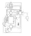
- the diesel engine 1 is associated with inlet air intake means thereof, which are designated by the general reference 2. At the output, this engine is associated with an exhaust line which is designated by the reference general 3.
- Means for recycling engine exhaust gas at the inlet thereof are also provided and are designated by the general reference 4.
- the exhaust line may also be associated with a turbocharger designated by the general reference 5 and more particularly to the turbine portion thereof, in a conventional manner.
- the exhaust line comprises an oxidation catalyst designated by the general reference 6, disposed upstream of a particulate filter designated by the general reference 7, disposed in the exhaust line.
- the engine is also associated with a fuel system for example common fuel cylinders thereof.
- This system is designated by the general reference 8 in this figure and comprises for example electrically operated high pressure injectors associated with these cylinders.
- the engine is a four-cylinder engine and therefore comprises four electrically operated injectors, respectively 9,10,11 and 12.
- injectors are associated for example with a common fuel supply ramp designated by the general reference 13 and connected to fuel supply means designated by the general reference 14, comprising for example a high pressure pump.
- These supply means are connected to a fuel tank designated by the general reference 15 and for example to means for adding to this fuel an additive intended to be deposited on the particulate filter to lower the combustion temperature of the fuel. particles trapped in it.
- this additive may for example be contained in an auxiliary tank designated by the general reference 16 associated with the fuel tank 15 to allow the injection of a certain amount of this additive into the fuel.
- this motor and the various components which have just been described are also associated with means for controlling their operation designated by the general reference 17 in this figure, comprising, for example, a suitable computer 18 associated with storage means. information 19, and connected in input to different means for acquiring information relating to different operating parameters of this engine and of these members, this calculator then being adapted to control the operation of the intake means, the recycling means, the turbocharger and / or the power system for controlling the operation of the engine and in particular the torque generated by it according to the driving conditions of the vehicle in a conventional manner.
- this calculator is connected to a differential pressure sensor 20 at the terminals of the catalyst and of the particle filter, respectively 6 and 7, at one or more temperature sensors 21, 22 and 23, respectively upstream of the catalyst, between this catalyst and the particulate filter and downstream of the particulate filter in the exhaust line.
- the pressure sensor 20 can also be connected to the terminals of the filter alone.
- the computer may also receive oxygen content information of the exhaust gas from a Lambda probe designated by the general reference 24 in this figure, integrated into the exhaust line.
- this computer is adapted to control the air intake means, the exhaust gas recycling means, the turbocharger, the means for adding fuel to the additive, the fuel supply means of the common rail and the various injectors associated with the engine cylinders.
- this calculator is adapted to trigger a regeneration phase of the particulate filter by combustion of trapped particles therein by engaging a phase of multiple fuel injections into the engine cylinders during their expansion phase.
- the particles emitted by the engine during its operation are indeed trapped in the particulate filter. It is then necessary to regenerate it regularly by combustion of these particles.
- the control means 17 are also associated with means for determining the activation state of the oxidation catalyst 6 formed by the computer 18 thereof, in order, during the regeneration of the filter, to continuously adapt the conditions of unfolding the phase of multiple fuel injections into the engine cylinders to account for the activation state of the catalyst.
- Continuous monitoring of the activity level of the catalyst therefore makes it possible to continuously control the phasing and / or the quantity of fuel injected to continuously optimize the operation of the catalyst and therefore the temperature within this catalyst, avoiding any degradation of that catalyst. of particulate filter or engine and any production of fumes or odors.
- the activation state of the catalyst 6 may be determined by the computer 18 for example from the information supplied by the temperature sensors 21 at the catalyst inlet and 22 at the outlet thereof, in a conventional manner.
- the computer 18 is associated with an integrated numerical modeling of the catalyst to know its state of activity from the information provided by the sensors.
- the computer 18 which triggers the regeneration of the particulate filter.
- This regeneration is performed by post fuel injection.
- This post-injected fuel will ignite late and burn in the exhaust line and thus cause the filter right the combustion of soot.
- the time required to operate the combustion of soot trapped in the filter and therefore the amount of fuel to be post-injected is directly dependent on the operating point of the engine and in particular the temperature of the exhaust gas.
- the regeneration operation is, can not be triggered either, can be but with more or less fuel consumption.
- the presence of a particulate filter is therefore in itself a significant potential source of overconsumption of the engine.
- the present invention therefore proposes to control the operation of the filter and in particular the regeneration phase of the particulate filter not taking into account the single degree of filling of the filter as in the prior art, but mainly taking into account the overconsumption the engine generated by the operation of the filter and this, to minimize the importance of such overconsumption.
- the present invention proposes more precisely to find an optimum between too frequent regenerations which would induce a global overconsumption of the high engine linked to the numerous post-injections and regenerations too spaced which would also induce a global overconsumption of the high engine because of strong counter-effects. exhaust pressures.
- the optimization of the regeneration strategy therefore consists in choosing at best the triggering of the regeneration phases.
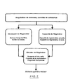
- supervisor constituted by a software program executed by the engine control computer 18.
- the supervisor receives via the computer 18 the information relating to the conditions of use of the vehicle and engine operation such as its speed, the position of the accelerator pedal, the rotation speed of the engine, etc.
- These different input information of the program are analyzed and at the output, the supervisor triggers and controls the regeneration phases of the filter.
- the supervisor can consist mainly of three modules.
- a first driving module called NR for Necessity to Regenerate, more particularly has the function of knowing the level of soot load of the filter and its consequences on the operation of the vehicle in terms of fuel consumption.
- a second module called CR for Capacity to Regenerate, evaluates the efficiency of a regeneration request under current or future engine operating conditions.
- a third module called D, to Decide exploits the information received from the first two modules and triggers the regeneration phases by minimizing the impact on the engine consumption and in critical cases ensures the operational safety of the filter and the engine.
- the first module NR is itself composed of two sub-modules.
- the first submodule NR_MCF provides the level of charge of the filter mass of carbonaceous particles only. It is a question of respecting the specifications of the supplier of the ceramic forming the filter body and in particular the maximum permissible load of carbon so as not to damage the filter during critical regeneration that is to say low flow and high soot mass.
- the indicator at the output of this submodule must characterize different states of charge from the "empty" state to the "maximum load” state.
- the second submodule of the NR module is the submodule NR_MS which provides the optimal regeneration distance, evaluated from the last regeneration date.
- the optimal regeneration distance will vary regularly depending on the driving conditions encountered by the vehicle.
- the indicator at the output of the module must characterize the optimal regeneration distance of the filter and the situation of the vehicle with respect to this optimum.
- the second module CR is also composed of two submodules.
- the first submodule CR_MCT characterizes the regeneration capacity under the current conditions of use of the engine and one of the output indicators of the module is the success rate of a possible regeneration performed under the present conditions and the second sub-module CR_MLT characterizes the regeneration capacity to come and the output indicator is the probability of meeting more favorable conditions for regeneration than the present conditions.
- the areas of use of the vehicle and the engine have been segmented into a predetermined number N of rolling types Ri (with i ranging from 1 to N).
- N rolling types
- the operating range of the motor has been broken down into 5 types of rolling and the parameters selected to characterize these types are the engine torque and the vehicle travel speed.
- N being able to be more or less important, in particular according to the microprocessor calculation capacities equipping the computer 18, likewise the parameters used to characterize the types of operation. can be more or less numerous, one could for example take into account the engine speed, the temperature of the coolant, etc.
- Each type of rolling Ri is therefore defined to correspond to a substantially homogeneous operation vis-à-vis the particulate filter.
- the optimum distance DistOptRege Rj regeneration minimizing the overconsumption associated with the regeneration phase filter is then determined (assuming that the engine operates in steady state steady state within this type of regeneration. rolling). This distance is defined from the end of the last regeneration performed on the filter.
- a distance DistOptRege is determined relative to the filling of the filter.
- the regeneration time of the filter DureeRegeOpt Rj when it is initiated at the optimum distance of regeneration DistOptRege Rj, is also determined . Good obviously, for the type or types of rolling where a regeneration is not possible given the operating conditions that are encountered this time is not calculated.
- the submodule CR_MCT has a particular function to characterize the operation of the engine and the vehicle and to identify what type of rolling Ri it is. Based on the information received from the different sensors, the CR_MCT module periodically calculates the value of the type of running where the motor is located, this raw value is then filtered to eliminate the transients. This results in the information according to which the vehicle is at the present moment in a given type of running run Ri. The CR_MCT module also calculates the distance traveled in each type of taxi.
- the types of rolling thus determined are stored and counted from the last regeneration observed in order to constitute a history of the types of driving followed by the vehicle.
- the operation of the vehicle and the engine is thus represented in the form of a succession of road sections, each section being characterized by a length in number of kilometers and a type of running. Of course other sizes could be taken into account to characterize a section like the driving time.
- M which is the number of sections successively encountered by the vehicle and the engine since the last regeneration up to the present moment, regularly increases as as the vehicle is used, until the moment of the new regeneration, which then resets the counters.
- the sub-module CR_MLT has more particularly its function of predictively determining the next sections, that is to say those intended to be encountered during the present journey of the vehicle or future trips.
- This sub-module CR_MLT uses the results of the submodule CR_MCT it deals with statistics and / or specific information provided by a navigation system onboard the vehicle.
- the computer 18 is adapted to construct a history of the conditions of use of the vehicle and to trigger the storage thereof in the means 19.
- This history makes it possible to calculate the probability of meeting conditions of use of the vehicle more favorable than the current conditions of use.
- This statistical information on the conditions of use of the vehicle gives an indication as to whether or not to postpone the initiation of the regeneration.
- a favorable statistical indication authorizes a postponement of this trigger in the case where short-term conditions are not favorable.
- a navigation system 30 is for example of the type able to provide a route after entering the destination or when this destination is otherwise known and to guide the motorist along this route using for example the GPS technology.
- Such a device specific or integrated with a radio device, may also be able to receive information on road traffic and traffic restrictions in order to refine its guidance.
- This navigation system is therefore adapted to communicate to the engine control information on the nature of the path and the traffic conditions to be transcribed into types of operation running of the engine.
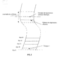
- the CR_MLT module is able to predict on a predetermined horizon, the conditions of vehicle circulation and engine operation. It is then able to discretize this horizon in the form of a succession of elementary sections T k each corresponding to a given type of rolling of the vehicle.
- This discretization can, for example, be expressed in the form of the following series of sections (taking as a reference the current position of the vehicle): section T M + 1 : over 10km circulation in rolling type R 1 , section T M +2 : over 25km traffic in rolling type R 3 , T M + 2 : 50km in rolling type R 5 , T M + 4 : again 5 km in rolling type R 1 , etc.
- the lowest time is then determined among the different calculated times, and the optimum regeneration distance is then determined to be that corresponding to the moment of initiation of the regeneration having caused this weakest time.
- the optimum regeneration distance is then determined to be that corresponding to the moment of initiation of the regeneration having caused this weakest time. In the case of equality between two times, it is the one that has the start or end instant closest to the optimal distance of theoretical regeneration which will be preferred and the optimal distance of actual regeneration will be defined from the latter.
Landscapes
- Engineering & Computer Science (AREA)
- Chemical & Material Sciences (AREA)
- Combustion & Propulsion (AREA)
- Mechanical Engineering (AREA)
- General Engineering & Computer Science (AREA)
- Processes For Solid Components From Exhaust (AREA)
Claims (9)
- Verfahren zur Steuerung des Regenerierens einer Falle (7) für verschmutzende Substanzen, die von einem Verbrennungsmotor abgegeben werden, der ein Kraft- oder Straßenfahrzeug ausstattet, das Steuermittel (9, 10, 11, 12) aufweist, die dazu bestimmt sind, die Falle (7) regelmäßig zu regenerieren, indem die Substanzen beseitigt werden, die dort gefangen sind, dadurch gekennzeichnet, dass der Zeitpunkt des Regenerierens derart ausgewählt wird, dass die Dauer des Regenerierens beschränkt und der Überverbrauch des Motors, der durch die Falle erzeugt wird, beschränkt wird, wobei die Auswahl des Zeitpunkts auf der Kenntnis der vergangenen Betriebsbedingungen des Fahrzeugs, die seit dem letzten Regenerieren aufgetreten sind, und auf der Schätzung der zukünftigen Betriebsbedingungen des Fahrzeugs beruht, wobei diese zukünftigen Bedingungen von Vorhersagemitteln (30) des Betriebs des Fahrzeugs geliefert werden, wobei das Bestimmen des Regenerierungszeitpunkts darin besteht, einen ersten theoretischen optimalen Regenerierungszeitpunkt zu suchen, der den Überverbrauch an Kraftstoff des Motors minimiert, dann zu beiden Seiten des ersten Zeitpunkts innerhalb eines vorbestimmten Intervalls einen zweiten Regenerierungszeitpunkt zu suchen, der ein schnelles Regenerieren erlaubt, wobei der zweite Zeitpunkt der Zeitpunkt ist, der ausgewählt wird, um das effektive Regenerieren der Falle auszuführen.
- Regenerierungsverfahren nach Anspruch 1, dadurch gekennzeichnet, dass der Zeitpunkt des Regenerierens in der Form einer Anzahl von Kilometern, die das Fahrzeug ab der letzten Regenerierung zu fahren hat, definiert ist.
- Regenerierungsverfahren nach einem der Ansprüche 1 oder 2, dadurch gekennzeichnet, dass die Vorhersagemittel des zukünftigen Betriebs des Fahrzeugs ein Navigationssystem (30) und/oder Systeme des Typs Verkehrsrundfunk aufweisen, die die Route des Fahrzeugs und/oder die kommenden Verkehrsbedingungen bestimmen können.
- Regenerierungsverfahren nach einem der Ansprüche 1 oder 2, dadurch gekennzeichnet, dass die zukünftigen Betriebsbedingungen aus zuvor von dem Fahrzeug angetroffenen Betriebsbedingungen abgeleitet werden.
- Regenerierungsverfahren nach einem der vorhergehenden Ansprüche, dadurch gekennzeichnet, dass die Betriebsbedingungen des Fahrzeugs ausgehend von einer finiten Anzahl von Fahrtypen modelliert werden, wobei jedem Fahrtyp Betriebsbereiche entsprechen, die von den Werten definiert werden, die entsprechende Größen, wie zum Beispiel die Fahrzeuggeschwindigkeit und das Motordrehmoment, annehmen.
- Regenerierungsverfahren nach Anspruch 5, dadurch gekennzeichnet, dass mit jedem Fahrtyp eine Regenerierungsentfernung verbunden ist, die den Überverbrauch an Kraftstoff und eine entsprechende Regenerierungsdauer optimiert.
- Regenerierungsverfahren nach Anspruch 5, dadurch gekennzeichnet, dass der vergangene und der zukünftige Betrieb des Fahrzeugs in der Form einer Abfolge von Abschnitten ausgedrückt ist, wobei jeder Abschnitt von einem gegebenen Fahrtyp und von einer charakteristischen Information, wie zum Beispiel seiner Länge in Anzahl von Kilometern definiert ist.
- Regenerierungsverfahren nach Anspruch 7, dadurch gekennzeichnet, dass der erste theoretische optimale Regenerierungszeitpunkt durch die generische Formel bestimmt wird:

wobei Di die innerhalb des i. Abschnitts zurückgelegte Entfernung ist und wobei DistOptRegeRi die theoretische optimale Regenerierungsentfernung für den Fahrtyp ist, der dem i. Abschnitt entspricht. - Regenerierungsverfahren nach Anspruch 1, dadurch gekennzeichnet, dass die Länge des Intervalls um den theoretischen optimalen Regenerierungszeitpunkt kleiner oder gleich in etwa 30 % der entsprechenden Entfernung im theoretischen optimalen Regenerierungszeitpunkt ist.
Applications Claiming Priority (2)
| Application Number | Priority Date | Filing Date | Title |
|---|---|---|---|
| FR0313897 | 2003-11-27 | ||
| FR0313897A FR2863005B1 (fr) | 2003-11-27 | 2003-11-27 | Procede de commande de la regeneration d'un piege integre dans la ligne d'echappement d'un moteur a combustion interne et systeme pour sa mise en oeuvre |
Publications (2)
| Publication Number | Publication Date |
|---|---|
| EP1536109A1 EP1536109A1 (de) | 2005-06-01 |
| EP1536109B1 true EP1536109B1 (de) | 2009-04-22 |
Family
ID=34451677
Family Applications (1)
| Application Number | Title | Priority Date | Filing Date |
|---|---|---|---|
| EP04300805A Expired - Lifetime EP1536109B1 (de) | 2003-11-27 | 2004-11-22 | Verfahren und Vorrichtung zur Steuerung der Regenerierung eines Partikelfilters in einer Verbrennungsmotorabgaseinrichtung |
Country Status (4)
| Country | Link |
|---|---|
| EP (1) | EP1536109B1 (de) |
| AT (1) | ATE429571T1 (de) |
| DE (1) | DE602004020724D1 (de) |
| FR (1) | FR2863005B1 (de) |
Cited By (2)
| Publication number | Priority date | Publication date | Assignee | Title |
|---|---|---|---|---|
| DE102016202997A1 (de) * | 2016-02-25 | 2017-08-31 | Bayerische Motoren Werke Aktiengesellschaft | Verfahren und Steuereinheit zur Steuerung eines zyklischen Reinigungsvorgangs eines Tankentlüftungssystems in einem Kraftfahrzeug |
| DE102019203793A1 (de) * | 2019-03-20 | 2020-09-24 | Ford Global Technologies, Llc | Verfahren zum Regenerieren eines Dieselpartikelfilters eines Kraftfahrzeuges sowie Computerprogramm, Datenverarbeitungssystem und Speichermedium sowie Vorrichtung und Kraftfahrzeug |
Families Citing this family (15)
| Publication number | Priority date | Publication date | Assignee | Title |
|---|---|---|---|---|
| DE102004005072B4 (de) | 2004-02-02 | 2018-06-07 | Robert Bosch Gmbh | Verfahren zum Regenerieren einer Abgasnachbehandlungsanlage |
| US7466087B2 (en) * | 2006-03-09 | 2008-12-16 | Deere & Company | Method and system for adaptively controlling a hybrid vehicle |
| US7640084B2 (en) * | 2006-03-09 | 2009-12-29 | Deere & Company | Method and system for adaptively controlling a hybrid vehicle |
| FR2906301B1 (fr) * | 2006-09-27 | 2008-11-07 | Renault Sas | Procede et dispositif de controle d'un systeme de depollution et vehicule muni du dispositif |
| FR2911368B1 (fr) | 2007-01-12 | 2009-08-21 | Renault Sas | Systeme et procede de controle de la regeneration d'un filtre a particules |
| US8572951B2 (en) | 2007-08-14 | 2013-11-05 | General Electric Company | System and method for regenerating a particulate filter |
| US8240138B2 (en) | 2007-08-14 | 2012-08-14 | General Electric Company | System and method for reducing particulate matter emission in diesel exhaust gas |
| US7925431B2 (en) * | 2007-08-14 | 2011-04-12 | General Electric Company | System and method for removing particulate matter from a diesel particulate filter |
| DE102007052292A1 (de) * | 2007-11-02 | 2009-05-07 | Robert Bosch Gmbh | Vorrichtung und Verfahren insbesondere zur Verbesserung einer Regeneration von Abgasnachbehandlungsvorrichtungen |
| DE102008042738A1 (de) * | 2008-10-10 | 2010-04-15 | Robert Bosch Gmbh | Vorrichtung und Verfahren zur Verbesserung einer Regeneration eines Dieselrußpartikelfilters |
| GB2479196B (en) * | 2010-04-01 | 2016-10-26 | Ford Global Tech Llc | A method for regenerating a particulate filter |
| FR2966874B1 (fr) * | 2010-10-27 | 2012-11-16 | Peugeot Citroen Automobiles Sa | Procede pour determiner l'etat du filtre a particules place sur la ligne d'echappement d'un vehicule automobile |
| FR3085056A1 (fr) * | 2018-08-17 | 2020-02-21 | Psa Automobiles Sa | Procede de planification de la regeneration d’un filtre a particules sur un trajet de roulage |
| FR3085996A1 (fr) * | 2018-09-18 | 2020-03-20 | Psa Automobiles Sa | Procede d'etablissement d'une cartographie de la qualite d'une regeneration d'un filtre a particules |
| CN114810297B (zh) * | 2022-05-19 | 2023-07-18 | 潍柴动力股份有限公司 | 一种柴油机颗粒捕集器再生的控制方法及装置 |
Family Cites Families (7)
| Publication number | Priority date | Publication date | Assignee | Title |
|---|---|---|---|---|
| JPH0524665A (ja) * | 1991-07-17 | 1993-02-02 | Kubota Corp | 積層荷物の送出装置 |
| KR100287049B1 (ko) * | 1995-10-30 | 2001-05-02 | 와다 아끼히로 | 내연기관용 배기 가스 정화 장치 |
| JP3395519B2 (ja) * | 1996-05-30 | 2003-04-14 | トヨタ自動車株式会社 | 内燃機関の蒸発燃料処理装置 |
| JP3596170B2 (ja) * | 1996-06-06 | 2004-12-02 | トヨタ自動車株式会社 | 内燃機関の補機駆動制御装置 |
| US6216676B1 (en) * | 1998-10-07 | 2001-04-17 | Toyota Jidosha Kabushiki Kaisha | Internal combustion engine system |
| JP2000240431A (ja) * | 1999-02-18 | 2000-09-05 | Nissan Motor Co Ltd | 内燃機関の排気浄化装置 |
| DE19948236A1 (de) * | 1999-10-06 | 2001-04-12 | Bosch Gmbh Robert | Steuergerät zur Reinigung eines Speicherkats eines Kraftfahrzeugs |
-
2003
- 2003-11-27 FR FR0313897A patent/FR2863005B1/fr not_active Expired - Fee Related
-
2004
- 2004-11-22 AT AT04300805T patent/ATE429571T1/de not_active IP Right Cessation
- 2004-11-22 EP EP04300805A patent/EP1536109B1/de not_active Expired - Lifetime
- 2004-11-22 DE DE602004020724T patent/DE602004020724D1/de not_active Expired - Lifetime
Cited By (3)
| Publication number | Priority date | Publication date | Assignee | Title |
|---|---|---|---|---|
| DE102016202997A1 (de) * | 2016-02-25 | 2017-08-31 | Bayerische Motoren Werke Aktiengesellschaft | Verfahren und Steuereinheit zur Steuerung eines zyklischen Reinigungsvorgangs eines Tankentlüftungssystems in einem Kraftfahrzeug |
| DE102019203793A1 (de) * | 2019-03-20 | 2020-09-24 | Ford Global Technologies, Llc | Verfahren zum Regenerieren eines Dieselpartikelfilters eines Kraftfahrzeuges sowie Computerprogramm, Datenverarbeitungssystem und Speichermedium sowie Vorrichtung und Kraftfahrzeug |
| DE102019203793B4 (de) | 2019-03-20 | 2023-02-16 | Ford Global Technologies, Llc | Verfahren zum Regenerieren eines Dieselpartikelfilters eines Kraftfahrzeuges sowie Computerprogramm, Datenverarbeitungssystem und Speichermedium sowie Vorrichtung und Kraftfahrzeug |
Also Published As
| Publication number | Publication date |
|---|---|
| FR2863005B1 (fr) | 2006-03-10 |
| FR2863005A1 (fr) | 2005-06-03 |
| DE602004020724D1 (de) | 2009-06-04 |
| ATE429571T1 (de) | 2009-05-15 |
| EP1536109A1 (de) | 2005-06-01 |
Similar Documents
| Publication | Publication Date | Title |
|---|---|---|
| EP1536109B1 (de) | Verfahren und Vorrichtung zur Steuerung der Regenerierung eines Partikelfilters in einer Verbrennungsmotorabgaseinrichtung | |
| GB2479196A (en) | Method for regenerating a particulate filter using a navigation system | |
| FR2865767A1 (fr) | Procede de regeneration d'une installation de traitement aval de gaz d'echappement | |
| FR3024885A1 (fr) | Procede et dispositif de reduction des emissions d'oxydes d'azote et d'ammoniac dans un systeme de post-traitement des gaz d'echappement d'un moteur thermique pendant les alternances de charge | |
| FR2829798A1 (fr) | Procede de gestion du fonctionnement d'un filtre a particules revetu d'une phase catalytique pour moteur a combustion | |
| EP1203877B1 (de) | Vorrichtung zur Regenerierung eines Partikelfilters in einer selbstgezündeten Brennkraftmaschine | |
| WO2010061085A1 (fr) | Procédé de pilotage d'un moteur a combustion interne et moteur a combustion interne correspondant | |
| FR2833653A1 (fr) | Systeme de recyclage des gaz d'echappement pour moteur diesel de vehicule automobile | |
| EP1203876B1 (de) | System für die Unterstützung der Regeneration eines Partikelfilters in einer selbstgezündeten Brennkraftmaschine | |
| EP1209333B1 (de) | Verfahren zum Regenerieren eines Partikelfilters | |
| EP2802760B1 (de) | Optimierte verwaltung eines scr-katalysators mittels periodischer regeneration eines partikelfilters | |
| EP1769140B1 (de) | System für die unterstützung der regeneration einer abgasanlage | |
| FR2970040A1 (fr) | Dispositif de regeneration d'un filtre a particules equipant une ligne d'echappement d'un moteur thermique | |
| EP1413720B1 (de) | Verfahren zum Ermitteln der Innentemperatur eines Partikelfilters, Verfahren zur Steuerung der Regeneration des Partikelfilters, sowie Steuerungssystem und Partikelfilter | |
| FR2976319A1 (fr) | Procede de gestion de la regeneration d'un filtre a particules | |
| FR2936995A3 (fr) | Regeneration d'un dispositif de post-traitement assistee par navigateur | |
| FR2872202A1 (fr) | Systeme d'aide a la regeneration de moyens de depollution pour moteur de vehicule automobile | |
| FR3084402A1 (fr) | Procede de prediction d’une temperature estimee de fluide de refroidissement d’un moteur lors d’un prochain trajet | |
| EP2604832A1 (de) | Verfahren zur Optimierung des Verbrennungsverfahrens von umweltverschmutzenden Partikeln, die von einer Wärmekraftmaschine eines Fahrzeugs ausgestoßen werden | |
| EP2771551B1 (de) | Verfahren und vorrichtung zur einstellung des verbrauchs eines verschmutzungsentfernungsmittels durch eine abgasleitung eines hybridfahrzeugs entsprechend verschiedenen antriebsmodi | |
| FR3073428B1 (fr) | Procede d’adaptation de l’additivation aux emissions pour aide a la regeneration d’un filtre a particules | |
| FR2872215A1 (fr) | Systeme de determination d'une fenetre optimale de declenchement d'une regeneration de moyens de depollution | |
| FR3085056A1 (fr) | Procede de planification de la regeneration d’un filtre a particules sur un trajet de roulage | |
| FR2801636A1 (fr) | Procede de regeneration d'un filtre a particules | |
| FR2872210A1 (fr) | Systeme d'aide a la regeneration de moyens de depollution pour vehicule automobile |
Legal Events
| Date | Code | Title | Description |
|---|---|---|---|
| PUAI | Public reference made under article 153(3) epc to a published international application that has entered the european phase |
Free format text: ORIGINAL CODE: 0009012 |
|
| AK | Designated contracting states |
Kind code of ref document: A1 Designated state(s): AT BE BG CH CY CZ DE DK EE ES FI FR GB GR HU IE IS IT LI LU MC NL PL PT RO SE SI SK TR |
|
| AX | Request for extension of the european patent |
Extension state: AL HR LT LV MK YU |
|
| 17P | Request for examination filed |
Effective date: 20050715 |
|
| AKX | Designation fees paid |
Designated state(s): AT BE BG CH CY CZ DE DK EE ES FI FR GB GR HU IE IS IT LI LU MC NL PL PT RO SE SI SK TR |
|
| 17Q | First examination report despatched |
Effective date: 20061208 |
|
| GRAP | Despatch of communication of intention to grant a patent |
Free format text: ORIGINAL CODE: EPIDOSNIGR1 |
|
| GRAS | Grant fee paid |
Free format text: ORIGINAL CODE: EPIDOSNIGR3 |
|
| GRAA | (expected) grant |
Free format text: ORIGINAL CODE: 0009210 |
|
| AK | Designated contracting states |
Kind code of ref document: B1 Designated state(s): AT BE BG CH CY CZ DE DK EE ES FI FR GB GR HU IE IS IT LI LU MC NL PL PT RO SE SI SK TR |
|
| REG | Reference to a national code |
Ref country code: GB Ref legal event code: FG4D Free format text: NOT ENGLISH |
|
| REG | Reference to a national code |
Ref country code: CH Ref legal event code: EP |
|
| REG | Reference to a national code |
Ref country code: IE Ref legal event code: FG4D |
|
| REF | Corresponds to: |
Ref document number: 602004020724 Country of ref document: DE Date of ref document: 20090604 Kind code of ref document: P |
|
| NLV1 | Nl: lapsed or annulled due to failure to fulfill the requirements of art. 29p and 29m of the patents act | ||
| PG25 | Lapsed in a contracting state [announced via postgrant information from national office to epo] |
Ref country code: PT Free format text: LAPSE BECAUSE OF FAILURE TO SUBMIT A TRANSLATION OF THE DESCRIPTION OR TO PAY THE FEE WITHIN THE PRESCRIBED TIME-LIMIT Effective date: 20090822 Ref country code: AT Free format text: LAPSE BECAUSE OF FAILURE TO SUBMIT A TRANSLATION OF THE DESCRIPTION OR TO PAY THE FEE WITHIN THE PRESCRIBED TIME-LIMIT Effective date: 20090422 Ref country code: ES Free format text: LAPSE BECAUSE OF FAILURE TO SUBMIT A TRANSLATION OF THE DESCRIPTION OR TO PAY THE FEE WITHIN THE PRESCRIBED TIME-LIMIT Effective date: 20090802 Ref country code: FI Free format text: LAPSE BECAUSE OF FAILURE TO SUBMIT A TRANSLATION OF THE DESCRIPTION OR TO PAY THE FEE WITHIN THE PRESCRIBED TIME-LIMIT Effective date: 20090422 |
|
| REG | Reference to a national code |
Ref country code: GB Ref legal event code: 746 Effective date: 20091012 |
|
| PG25 | Lapsed in a contracting state [announced via postgrant information from national office to epo] |
Ref country code: IS Free format text: LAPSE BECAUSE OF FAILURE TO SUBMIT A TRANSLATION OF THE DESCRIPTION OR TO PAY THE FEE WITHIN THE PRESCRIBED TIME-LIMIT Effective date: 20090822 Ref country code: SI Free format text: LAPSE BECAUSE OF FAILURE TO SUBMIT A TRANSLATION OF THE DESCRIPTION OR TO PAY THE FEE WITHIN THE PRESCRIBED TIME-LIMIT Effective date: 20090422 Ref country code: NL Free format text: LAPSE BECAUSE OF FAILURE TO SUBMIT A TRANSLATION OF THE DESCRIPTION OR TO PAY THE FEE WITHIN THE PRESCRIBED TIME-LIMIT Effective date: 20090422 Ref country code: PL Free format text: LAPSE BECAUSE OF FAILURE TO SUBMIT A TRANSLATION OF THE DESCRIPTION OR TO PAY THE FEE WITHIN THE PRESCRIBED TIME-LIMIT Effective date: 20090422 Ref country code: SE Free format text: LAPSE BECAUSE OF FAILURE TO SUBMIT A TRANSLATION OF THE DESCRIPTION OR TO PAY THE FEE WITHIN THE PRESCRIBED TIME-LIMIT Effective date: 20090722 |
|
| REG | Reference to a national code |
Ref country code: IE Ref legal event code: FD4D |
|
| PG25 | Lapsed in a contracting state [announced via postgrant information from national office to epo] |
Ref country code: DK Free format text: LAPSE BECAUSE OF FAILURE TO SUBMIT A TRANSLATION OF THE DESCRIPTION OR TO PAY THE FEE WITHIN THE PRESCRIBED TIME-LIMIT Effective date: 20090422 Ref country code: EE Free format text: LAPSE BECAUSE OF FAILURE TO SUBMIT A TRANSLATION OF THE DESCRIPTION OR TO PAY THE FEE WITHIN THE PRESCRIBED TIME-LIMIT Effective date: 20090422 Ref country code: RO Free format text: LAPSE BECAUSE OF FAILURE TO SUBMIT A TRANSLATION OF THE DESCRIPTION OR TO PAY THE FEE WITHIN THE PRESCRIBED TIME-LIMIT Effective date: 20090422 Ref country code: IE Free format text: LAPSE BECAUSE OF FAILURE TO SUBMIT A TRANSLATION OF THE DESCRIPTION OR TO PAY THE FEE WITHIN THE PRESCRIBED TIME-LIMIT Effective date: 20090422 Ref country code: CZ Free format text: LAPSE BECAUSE OF FAILURE TO SUBMIT A TRANSLATION OF THE DESCRIPTION OR TO PAY THE FEE WITHIN THE PRESCRIBED TIME-LIMIT Effective date: 20090422 |
|
| PG25 | Lapsed in a contracting state [announced via postgrant information from national office to epo] |
Ref country code: SK Free format text: LAPSE BECAUSE OF FAILURE TO SUBMIT A TRANSLATION OF THE DESCRIPTION OR TO PAY THE FEE WITHIN THE PRESCRIBED TIME-LIMIT Effective date: 20090422 |
|
| PLBE | No opposition filed within time limit |
Free format text: ORIGINAL CODE: 0009261 |
|
| STAA | Information on the status of an ep patent application or granted ep patent |
Free format text: STATUS: NO OPPOSITION FILED WITHIN TIME LIMIT |
|
| 26N | No opposition filed |
Effective date: 20100125 |
|
| PG25 | Lapsed in a contracting state [announced via postgrant information from national office to epo] |
Ref country code: BG Free format text: LAPSE BECAUSE OF FAILURE TO SUBMIT A TRANSLATION OF THE DESCRIPTION OR TO PAY THE FEE WITHIN THE PRESCRIBED TIME-LIMIT Effective date: 20090722 |
|
| BERE | Be: lapsed |
Owner name: PEUGEOT CITROEN AUTOMOBILES SA Effective date: 20091130 |
|
| PG25 | Lapsed in a contracting state [announced via postgrant information from national office to epo] |
Ref country code: MC Free format text: LAPSE BECAUSE OF NON-PAYMENT OF DUE FEES Effective date: 20091130 |
|
| REG | Reference to a national code |
Ref country code: CH Ref legal event code: PL |
|
| PG25 | Lapsed in a contracting state [announced via postgrant information from national office to epo] |
Ref country code: CH Free format text: LAPSE BECAUSE OF NON-PAYMENT OF DUE FEES Effective date: 20091130 Ref country code: BE Free format text: LAPSE BECAUSE OF NON-PAYMENT OF DUE FEES Effective date: 20091130 Ref country code: GR Free format text: LAPSE BECAUSE OF FAILURE TO SUBMIT A TRANSLATION OF THE DESCRIPTION OR TO PAY THE FEE WITHIN THE PRESCRIBED TIME-LIMIT Effective date: 20090723 Ref country code: LI Free format text: LAPSE BECAUSE OF NON-PAYMENT OF DUE FEES Effective date: 20091130 |
|
| PG25 | Lapsed in a contracting state [announced via postgrant information from national office to epo] |
Ref country code: IT Free format text: LAPSE BECAUSE OF FAILURE TO SUBMIT A TRANSLATION OF THE DESCRIPTION OR TO PAY THE FEE WITHIN THE PRESCRIBED TIME-LIMIT Effective date: 20090422 |
|
| PG25 | Lapsed in a contracting state [announced via postgrant information from national office to epo] |
Ref country code: LU Free format text: LAPSE BECAUSE OF NON-PAYMENT OF DUE FEES Effective date: 20091122 |
|
| PG25 | Lapsed in a contracting state [announced via postgrant information from national office to epo] |
Ref country code: HU Free format text: LAPSE BECAUSE OF FAILURE TO SUBMIT A TRANSLATION OF THE DESCRIPTION OR TO PAY THE FEE WITHIN THE PRESCRIBED TIME-LIMIT Effective date: 20091023 |
|
| PG25 | Lapsed in a contracting state [announced via postgrant information from national office to epo] |
Ref country code: TR Free format text: LAPSE BECAUSE OF FAILURE TO SUBMIT A TRANSLATION OF THE DESCRIPTION OR TO PAY THE FEE WITHIN THE PRESCRIBED TIME-LIMIT Effective date: 20090422 |
|
| PG25 | Lapsed in a contracting state [announced via postgrant information from national office to epo] |
Ref country code: CY Free format text: LAPSE BECAUSE OF FAILURE TO SUBMIT A TRANSLATION OF THE DESCRIPTION OR TO PAY THE FEE WITHIN THE PRESCRIBED TIME-LIMIT Effective date: 20090422 |
|
| REG | Reference to a national code |
Ref country code: FR Ref legal event code: PLFP Year of fee payment: 12 |
|
| REG | Reference to a national code |
Ref country code: FR Ref legal event code: PLFP Year of fee payment: 13 |
|
| REG | Reference to a national code |
Ref country code: DE Ref legal event code: R084 Ref document number: 602004020724 Country of ref document: DE |
|
| PGFP | Annual fee paid to national office [announced via postgrant information from national office to epo] |
Ref country code: FR Payment date: 20161024 Year of fee payment: 13 Ref country code: DE Payment date: 20161020 Year of fee payment: 13 Ref country code: GB Payment date: 20161027 Year of fee payment: 13 |
|
| REG | Reference to a national code |
Ref country code: DE Ref legal event code: R119 Ref document number: 602004020724 Country of ref document: DE |
|
| REG | Reference to a national code |
Ref country code: FR Ref legal event code: CA Effective date: 20180312 Ref country code: FR Ref legal event code: CD Owner name: PEUGEOT CITROEN AUTOMOBILES SA, FR Effective date: 20180312 |
|
| GBPC | Gb: european patent ceased through non-payment of renewal fee |
Effective date: 20171122 |
|
| REG | Reference to a national code |
Ref country code: FR Ref legal event code: ST Effective date: 20180731 |
|
| PG25 | Lapsed in a contracting state [announced via postgrant information from national office to epo] |
Ref country code: FR Free format text: LAPSE BECAUSE OF NON-PAYMENT OF DUE FEES Effective date: 20171130 Ref country code: DE Free format text: LAPSE BECAUSE OF NON-PAYMENT OF DUE FEES Effective date: 20180602 |
|
| PG25 | Lapsed in a contracting state [announced via postgrant information from national office to epo] |
Ref country code: GB Free format text: LAPSE BECAUSE OF NON-PAYMENT OF DUE FEES Effective date: 20171122 |