EP1536104A1 - Clausius-rankine-prozessvorrichtung - Google Patents
Clausius-rankine-prozessvorrichtung Download PDFInfo
- Publication number
- EP1536104A1 EP1536104A1 EP03766629A EP03766629A EP1536104A1 EP 1536104 A1 EP1536104 A1 EP 1536104A1 EP 03766629 A EP03766629 A EP 03766629A EP 03766629 A EP03766629 A EP 03766629A EP 1536104 A1 EP1536104 A1 EP 1536104A1
- Authority
- EP
- European Patent Office
- Prior art keywords
- evaporator
- temperature
- expander
- steam
- rotational speed
- Prior art date
- Legal status (The legal status is an assumption and is not a legal conclusion. Google has not performed a legal analysis and makes no representation as to the accuracy of the status listed.)
- Withdrawn
Links
- 239000012071 phase Substances 0.000 claims description 15
- 239000007791 liquid phase Substances 0.000 claims description 9
- 238000006073 displacement reaction Methods 0.000 claims description 5
- 238000010438 heat treatment Methods 0.000 claims description 4
- XLYOFNOQVPJJNP-UHFFFAOYSA-N water Substances O XLYOFNOQVPJJNP-UHFFFAOYSA-N 0.000 abstract description 52
- 230000004043 responsiveness Effects 0.000 abstract description 10
- 230000003247 decreasing effect Effects 0.000 abstract description 5
- 239000007789 gas Substances 0.000 description 25
- 239000000446 fuel Substances 0.000 description 11
- 230000007423 decrease Effects 0.000 description 6
- 230000001276 controlling effect Effects 0.000 description 4
- 239000002918 waste heat Substances 0.000 description 3
- 238000010586 diagram Methods 0.000 description 2
- 230000001105 regulatory effect Effects 0.000 description 2
- 230000004044 response Effects 0.000 description 2
- 229920006395 saturated elastomer Polymers 0.000 description 2
- 238000001816 cooling Methods 0.000 description 1
- 238000001704 evaporation Methods 0.000 description 1
- 230000008020 evaporation Effects 0.000 description 1
- 238000002347 injection Methods 0.000 description 1
- 239000007924 injection Substances 0.000 description 1
- 238000000034 method Methods 0.000 description 1
Images


Classifications
-
- F—MECHANICAL ENGINEERING; LIGHTING; HEATING; WEAPONS; BLASTING
- F01—MACHINES OR ENGINES IN GENERAL; ENGINE PLANTS IN GENERAL; STEAM ENGINES
- F01K—STEAM ENGINE PLANTS; STEAM ACCUMULATORS; ENGINE PLANTS NOT OTHERWISE PROVIDED FOR; ENGINES USING SPECIAL WORKING FLUIDS OR CYCLES
- F01K13/00—General layout or general methods of operation of complete plants
- F01K13/02—Controlling, e.g. stopping or starting
-
- F—MECHANICAL ENGINEERING; LIGHTING; HEATING; WEAPONS; BLASTING
- F01—MACHINES OR ENGINES IN GENERAL; ENGINE PLANTS IN GENERAL; STEAM ENGINES
- F01K—STEAM ENGINE PLANTS; STEAM ACCUMULATORS; ENGINE PLANTS NOT OTHERWISE PROVIDED FOR; ENGINES USING SPECIAL WORKING FLUIDS OR CYCLES
- F01K23/00—Plants characterised by more than one engine delivering power external to the plant, the engines being driven by different fluids
- F01K23/02—Plants characterised by more than one engine delivering power external to the plant, the engines being driven by different fluids the engine cycles being thermally coupled
- F01K23/06—Plants characterised by more than one engine delivering power external to the plant, the engines being driven by different fluids the engine cycles being thermally coupled combustion heat from one cycle heating the fluid in another cycle
- F01K23/065—Plants characterised by more than one engine delivering power external to the plant, the engines being driven by different fluids the engine cycles being thermally coupled combustion heat from one cycle heating the fluid in another cycle the combustion taking place in an internal combustion piston engine, e.g. a diesel engine
-
- F—MECHANICAL ENGINEERING; LIGHTING; HEATING; WEAPONS; BLASTING
- F01—MACHINES OR ENGINES IN GENERAL; ENGINE PLANTS IN GENERAL; STEAM ENGINES
- F01K—STEAM ENGINE PLANTS; STEAM ACCUMULATORS; ENGINE PLANTS NOT OTHERWISE PROVIDED FOR; ENGINES USING SPECIAL WORKING FLUIDS OR CYCLES
- F01K23/00—Plants characterised by more than one engine delivering power external to the plant, the engines being driven by different fluids
- F01K23/02—Plants characterised by more than one engine delivering power external to the plant, the engines being driven by different fluids the engine cycles being thermally coupled
- F01K23/06—Plants characterised by more than one engine delivering power external to the plant, the engines being driven by different fluids the engine cycles being thermally coupled combustion heat from one cycle heating the fluid in another cycle
- F01K23/10—Plants characterised by more than one engine delivering power external to the plant, the engines being driven by different fluids the engine cycles being thermally coupled combustion heat from one cycle heating the fluid in another cycle with exhaust fluid of one cycle heating the fluid in another cycle
- F01K23/101—Regulating means specially adapted therefor
Definitions
- the present invention relates to a Rankine cycle system that includes an evaporator for heating a liquid-phase working medium with exhaust gas of an engine so as to generate a gas-phase working medium, and a displacement type expander for converting the thermal energy of the gas-phase working medium generated in the evaporator into mechanical energy.
- Japanese Utility Model Registration Publication No. 2-38161 discloses an arrangement in which the steam temperature at the outlet of a waste heat once-through boiler using, as a heat source, exhaust gas of an engine rotating at a constant speed is compared with a target steam temperature, and the amount of water supplied to the waste heat once-through boiler is feedback-controlled so as to make the steam temperature coincide with the target steam temperature, precision in control of the steam temperature being improved by adding, to the feedback signal, a feedforward signal calculated on the basis of the steam pressure at the outlet of the waste heat once-through boiler so as to compensate for fluctuations in the engine load.
- the present invention has been achieved under the above-mentioned circumstances, and it is an object thereof to control the temperature of a gas-phase working medium generated in an evaporator of a Rankine cycle system at a target temperature with good responsiveness and high precision.
- a Rankine cycle system that includes an evaporator for heating a liquid-phase working medium with exhaust gas of an engine so as to generate a gas-phase working medium, and a displacement type expander for converting the thermal energy of the gas-phase working medium generated in the evaporator into mechanical energy, characterized in that the system includes control means for controlling the amount of liquid-phase working medium supplied to the evaporator and the rotational speed of the expander so as to make the temperature of the gas-phase working medium at the outlet of the evaporator coincide with a target temperature.
- a controller 20 of embodiments corresponds to the control means of the present invention.
- a Rankine cycle system for recovering the thermal energy of exhaust gas of a vehicle engine 11 is formed from an evaporator 12 for heating a liquid-phase working medium (water) with the exhaust gas of the engine 11 and generating a high temperature, high pressure gas-phase working medium (steam), a displacement type expander 13 for converting the thermal energy of the high temperature, high pressure steam generated in the evaporator 12 into mechanical energy, a condenser 14 for cooling the steam discharged from the expander 13 and condensing it into water, a tank 15 for storing water discharged from the condenser 14, a water supply pump 16 for drawing up water out of the tank 15, and an injector 17 for injecting water drawn up by the water supply pump 16 into the evaporator 12, the above being arranged in a closed circuit.
- a motor/generator 18 connected to the expander 13 is disposed, for example, between the engine 11 and driven wheels; the motor/generator 18 can be made to function as a motor so as to assist the output of the engine 11, and when the vehicle is being decelerated the motor/generator 18 can be made to function as a generator so as to recover the kinetic energy of the vehicle as electrical energy.
- the motor/generator 18 may be connected to the expander 13 alone, and then exhibits only the function of generating electrical energy.
- the rotational speed of the expander 13 is controlled by regulating the load (amount of electric power generated) of the motor/generator 18 so as to regulate the load imposed on the expander 13 by the motor/generator 18.
- a controller 20 into which are input running conditions of the engine 11, that is, an engine rotational speed Ne, an intake negative pressure Pb, an exhaust gas temperature Tg, and an air fuel ratio A/F, together with a steam temperature T at the outlet of the evaporator 12 detected by a steam temperature sensor 19, controls the amount of water supplied from the injector 17 (or the rotational speed of the water supply pump 16) and the load generated by the motor/generator 18, that is, the rotational speed of the expander 13.
- FIG. 2A shows schematically the structure of the evaporator 12.
- a heat transfer pipe 22 disposed within a casing 21 of the evaporator 12 includes a water inlet 22a communicating with the injector 17, and a steam outlet 22b communicating with the expander 13, and the casing 21 includes an exhaust gas inlet 21a on the steam outlet 22b side and an exhaust gas outlet 21b on the water inlet 22a side.
- the working medium and the exhaust gas therefore flow in opposite directions to each other.
- the temperature of water supplied to the water inlet 22a of the heat transfer pipe 22 increases gradually in a liquid phase state, and when it reaches a saturation temperature at point a , it becomes wet saturated steam (two phase state) in which water and steam coexist and the saturation temperature is maintained.
- the temperature of this steam increases from the saturation temperature.
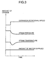
- FIG. 3 if the load of the motor/generator 18 is reduced and the rotational speed of the expander 13 is increased stepwise while keeping the amount of steam supplied to the expander 13 constant, the steam pressure decreases, and the steam temperature decreases temporarily due to the latent heat of evaporation of water and the heat of expansion of water.
- the saturation temperature decreases and point a and point b shift to the water inlet 22a side, and the temperature of steam discharged from the steam outlet 22b decreases temporarily.
- the speed of decrease in the steam temperature is proportional to the speed of decrease in the steam pressure and is on the order of a few seconds.
- the working medium within the heat transfer pipe 22 receives the thermal energy of exhaust gas, its temperature increases and, as shown in FIG. 3, its temperature returns to the temperature before the rotational speed of the expander 13 was increased. Since this temperature change is influenced by the heat capacity of the evaporator 12, it is on the order of a few tens of seconds to a few hundred seconds. In this way, by changing the rotational speed of the expander 13, it is possible to control the steam temperature at the outlet of the evaporator 12 with good responsiveness, although this is temporary.
- the amount of water supplied from the injector 17 to the evaporator 12 is controlled at the same time as the rotational speed of the expander 13 is changed.
- the amount of water supplied to the evaporator 12 is decreased stepwise as shown in FIG. 4A, the steam temperature at the outlet of the evaporator 12 increases slowly, taking on the order of a few tens of seconds to a few hundred seconds, and converges to a predetermined temperature.
- controlling the steam temperature by changing the amount of water supplied has very poor responsiveness, but by simultaneously temporarily increasing the steam temperature as shown in FIG. 4B by decreasing the rotational speed of the expander 13 stepwise it is possible, as shown in FIG. 4C, to control the steam temperature at a target steam temperature with good responsiveness and high precision, and as a result it is possible to maximize the total efficiency, which is the sum of the efficiency of the evaporator and the efficiency of the expander.
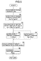
- step S1 the steam temperature T at the outlet of the evaporator 12 is detected by the steam temperature sensor 19, in step S2 the running conditions of the engine 11, that is, the engine rotational speed Ne, the intake negative pressure Pb, the exhaust gas temperature Tg, and the air fuel ratio A/F are detected, and in step S3 a water supply amount feedforward value Q FF is calculated on the basis of Ne, Pb, Tg, and A/F.
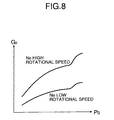
- FIG. 6 shows a sub routine of step S3 above; in step S11 a fuel flow rate G F of the engine 11 is looked up by applying the engine rotational speed Ne and the intake negative pressure Pb to the map of FIG. 8. The greater the engine rotational speed Ne and the higher the intake negative pressure Pb, the greater the fuel flow rate G F . The reason why the fuel flow rate G F rapidly increases in a region where the intake negative pressure Pb is high is because the fuel becomes rich when the load of the engine 11 is high.
- the exhaust gas flow rate G GAS is calculated from the air fuel ratio A/F and the fuel flow rate G F by means of (A/F + 1) ⁇ G F .
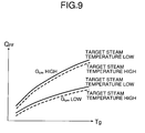
- step S13 the water supply amount feedforward value Q FF is looked up by applying the exhaust gas flow rate G GAS and the exhaust gas temperature Tg to the map of FIG. 9. The greater the exhaust gas flow rate G GAS and the higher the exhaust gas temperature Tg, the greater the water supply amount feedforward value Q FF .
- the water supply amount feedforward value Q FF is corrected so as to increase slightly in response to an increase in the target steam temperature T 0 .
- step S4 a water supply command value for the injector 17, that is, a degree-of-opening command value Ti for the injector 17, is calculated from the water supply amount feedforward value Q FF . Since the amount of water supplied changes in response to the rotational speed of the water supply pump 16, instead of step S4 above, in step S4' a water supply command value for the injector 17, that is, a rotational speed Np of the water supply pump 16, may be calculated from the water supply amount feedforward value Q FF .
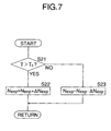
- step S5 a target rotational speed N EXP for the expander 13 in order to control the steam temperature T at a target steam temperature T 0 is calculated.
- FIG. 7 shows a sub routine of step S5 above; if in step S21 the steam temperature T exceeds the target steam temperature T 0 , then in step S22 an amount of rotational speed change ⁇ N EXP is added to the target expander rotational speed N EXP , whereas if the steam temperature T is equal to or less than the target steam temperature T 0 , then in step S23 the amount of rotational speed change ⁇ N EXP is subtracted from the target expander rotational speed N EXP .
- step S6 of the flowchart of FIG. 5 the target expander rotational speed N EXP is output as a command value, and the load generated by the motor/generator 18 is changed so as to control the rotational speed of the expander 13.
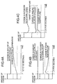
- FIG. 10 A second embodiment of the present invention is now explained with reference to FIG. 10 and FIG. 11.
- the flowchart of FIG. 10 is one in which steps S3A and S3B are added after step S3 (calculation of water supply amount feedforward value) of the flowchart (first embodiment) of FIG. 5, and the other steps are substantially the same.
- step S3A a water supply amount feedback value Q FB is obtained as a PID calculation value of a deviation T 0 - T of the steam temperature T from the target steam temperature T 0
- step S3B a water supply amount Q 0 is calculated by adding the water supply amount feedback value Q FB to a water supply amount feedforward value Q FF
- step S4 or step S4'
- a water supply amount command value is calculated on the basis of the water supply amount Q 0 .
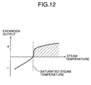
- step S5 When a target expander rotational speed N EXP is calculated in step S5 (see FIG. 7), as shown in FIG. 11, when the steam flow rate is low, even if an amount of rotational speed change ⁇ N EXP for the target expander rotational speed N EXP is small, the steam temperature can be changed, but when the steam flow rate is high, unless the amount of rotational speed change ⁇ N EXP for the target expander rotational speed N EXP is made large, the steam temperature cannot be changed.
- the expander rotational speed can be rapidly converged to the target expander rotational speed N EXP by increasing the amount of rotational speed change ⁇ N EXP when the deviation T 0 - T of the steam temperature T from the target steam temperature T 0 is large and by decreasing the amount of rotational speed change ⁇ N EXP when the deviation T 0 - T is small.
- the combined use of feedforward control and feedback control enables the expander rotational speed to be converged to the target expander rotational speed N EXP yet more precisely.
- the water supply amount feedforward value Q FF is calculated on the basis of Ne, Pb, Tg, and A/F, but it may be obtained by directly detecting an exhaust gas flow rate using a flow rate sensor.
- step S11 of the flowchart of FIG. 6 the fuel flow rate G F of the engine 11 is looked up from the map using the engine rotational speed Ne and the intake negative pressure Pb, but it may be calculated from a fuel injection quantity of the engine 11.
- the working medium is not limited to water (steam), and another appropriate working medium may be employed.
Landscapes
- Engineering & Computer Science (AREA)
- Chemical & Material Sciences (AREA)
- Combustion & Propulsion (AREA)
- Mechanical Engineering (AREA)
- General Engineering & Computer Science (AREA)
- Engine Equipment That Uses Special Cycles (AREA)
- Control Of Turbines (AREA)
- Control Of Steam Boilers And Waste-Gas Boilers (AREA)
Applications Claiming Priority (3)
| Application Number | Priority Date | Filing Date | Title |
|---|---|---|---|
| JP2002215257 | 2002-07-24 | ||
| JP2002215257A JP3901608B2 (ja) | 2002-07-24 | 2002-07-24 | ランキンサイクル装置 |
| PCT/JP2003/009223 WO2004013466A1 (ja) | 2002-07-24 | 2003-07-22 | ランキンサイクル装置 |
Publications (2)
| Publication Number | Publication Date |
|---|---|
| EP1536104A1 true EP1536104A1 (de) | 2005-06-01 |
| EP1536104A4 EP1536104A4 (de) | 2005-11-23 |
Family
ID=31492072
Family Applications (1)
| Application Number | Title | Priority Date | Filing Date |
|---|---|---|---|
| EP03766629A Withdrawn EP1536104A4 (de) | 2002-07-24 | 2003-07-22 | Clausius-rankine-prozessvorrichtung |
Country Status (5)
| Country | Link |
|---|---|
| US (1) | US20060086091A1 (de) |
| EP (1) | EP1536104A4 (de) |
| JP (1) | JP3901608B2 (de) |
| AU (1) | AU2003248086A1 (de) |
| WO (1) | WO2004013466A1 (de) |
Cited By (6)
| Publication number | Priority date | Publication date | Assignee | Title |
|---|---|---|---|---|
| WO2009109311A3 (de) * | 2008-03-06 | 2011-05-19 | Daimler Ag | Verfahren zum gewinnen von energie aus einem abgasstrom sowie entsprechendes kraftfahrzeug |
| WO2013007530A1 (de) * | 2011-07-14 | 2013-01-17 | Avl List Gmbh | Verfahren zur regelung einer wärmenutzungsvorrichtung bei einer brennkraftmaschine |
| DE102016005717A1 (de) | 2015-12-24 | 2017-01-26 | Daimler Ag | Vorrichtung und Verfahren zur Nutzung von Abwärme einer Verbrennungskraftmaschine in einem Kraftfahrzeug |
| US10598049B2 (en) | 2017-10-03 | 2020-03-24 | Enviro Power, Inc. | Evaporator with integrated heat recovery |
| US11204190B2 (en) | 2017-10-03 | 2021-12-21 | Enviro Power, Inc. | Evaporator with integrated heat recovery |
| TWI855653B (zh) * | 2023-04-26 | 2024-09-11 | 國立勤益科技大學 | 有機朗肯循環發電系統 |
Families Citing this family (8)
| Publication number | Priority date | Publication date | Assignee | Title |
|---|---|---|---|---|
| DE102005051428B4 (de) * | 2004-10-29 | 2015-05-28 | Denso Corporation | Abwärmenutzungsvorrichtung |
| JP4675717B2 (ja) * | 2004-11-19 | 2011-04-27 | 株式会社デンソー | 内燃機関の廃熱利用装置およびその制御方法 |
| JP4684762B2 (ja) * | 2005-06-27 | 2011-05-18 | 株式会社荏原製作所 | 発電装置 |
| US7950230B2 (en) * | 2007-09-14 | 2011-05-31 | Denso Corporation | Waste heat recovery apparatus |
| JP2011196209A (ja) * | 2010-03-18 | 2011-10-06 | Mitsubishi Electric Corp | 排熱回生システム |
| US20120047889A1 (en) * | 2010-08-27 | 2012-03-01 | Uop Llc | Energy Conversion Using Rankine Cycle System |
| JP6021637B2 (ja) * | 2012-12-28 | 2016-11-09 | 三菱重工業株式会社 | 発電システム、発電方法 |
| JP7372132B2 (ja) * | 2019-12-16 | 2023-10-31 | パナソニックホールディングス株式会社 | ランキンサイクル装置及びその運転方法 |
Family Cites Families (5)
| Publication number | Priority date | Publication date | Assignee | Title |
|---|---|---|---|---|
| US4358929A (en) * | 1974-04-02 | 1982-11-16 | Stephen Molivadas | Solar power system |
| US4117344A (en) * | 1976-01-02 | 1978-09-26 | General Electric Company | Control system for a rankine cycle power unit |
| JPH0633766B2 (ja) * | 1984-01-13 | 1994-05-02 | 株式会社東芝 | 動力装置 |
| JP2000345835A (ja) * | 1999-06-07 | 2000-12-12 | Nissan Motor Co Ltd | 内燃機関 |
| JP2001271609A (ja) * | 2000-01-18 | 2001-10-05 | Honda Motor Co Ltd | 内燃機関の廃熱回収装置 |
-
2002
- 2002-07-24 JP JP2002215257A patent/JP3901608B2/ja not_active Expired - Fee Related
-
2003
- 2003-07-22 US US10/521,960 patent/US20060086091A1/en not_active Abandoned
- 2003-07-22 WO PCT/JP2003/009223 patent/WO2004013466A1/ja not_active Ceased
- 2003-07-22 EP EP03766629A patent/EP1536104A4/de not_active Withdrawn
- 2003-07-22 AU AU2003248086A patent/AU2003248086A1/en not_active Abandoned
Non-Patent Citations (2)
| Title |
|---|
| No further relevant documents disclosed * |
| See also references of WO2004013466A1 * |
Cited By (8)
| Publication number | Priority date | Publication date | Assignee | Title |
|---|---|---|---|---|
| WO2009109311A3 (de) * | 2008-03-06 | 2011-05-19 | Daimler Ag | Verfahren zum gewinnen von energie aus einem abgasstrom sowie entsprechendes kraftfahrzeug |
| US8572964B2 (en) | 2008-03-06 | 2013-11-05 | Daimler Ag | Method for recuperating energy from an exhaust gas flow and motor vehicle |
| WO2013007530A1 (de) * | 2011-07-14 | 2013-01-17 | Avl List Gmbh | Verfahren zur regelung einer wärmenutzungsvorrichtung bei einer brennkraftmaschine |
| US9482150B2 (en) | 2011-07-14 | 2016-11-01 | Avl List Gmbh | Method for controlling a heat recovery device in an internal combustion engine |
| DE102016005717A1 (de) | 2015-12-24 | 2017-01-26 | Daimler Ag | Vorrichtung und Verfahren zur Nutzung von Abwärme einer Verbrennungskraftmaschine in einem Kraftfahrzeug |
| US10598049B2 (en) | 2017-10-03 | 2020-03-24 | Enviro Power, Inc. | Evaporator with integrated heat recovery |
| US11204190B2 (en) | 2017-10-03 | 2021-12-21 | Enviro Power, Inc. | Evaporator with integrated heat recovery |
| TWI855653B (zh) * | 2023-04-26 | 2024-09-11 | 國立勤益科技大學 | 有機朗肯循環發電系統 |
Also Published As
| Publication number | Publication date |
|---|---|
| WO2004013466A1 (ja) | 2004-02-12 |
| JP3901608B2 (ja) | 2007-04-04 |
| JP2004052738A (ja) | 2004-02-19 |
| EP1536104A4 (de) | 2005-11-23 |
| US20060086091A1 (en) | 2006-04-27 |
| AU2003248086A1 (en) | 2004-02-23 |
Similar Documents
| Publication | Publication Date | Title |
|---|---|---|
| EP1536104A1 (de) | Clausius-rankine-prozessvorrichtung | |
| US20060254276A1 (en) | Rankine cycle system | |
| US7950230B2 (en) | Waste heat recovery apparatus | |
| JP5462979B2 (ja) | 熱サイクルプロセスの制御 | |
| RU2638890C2 (ru) | Способ регулирования системы утилизации тепла в транспортном средстве | |
| WO2010070786A1 (ja) | 排熱回生システム | |
| JP6604355B2 (ja) | 廃熱回収装置 | |
| CN103154442A (zh) | 用于内燃机的废热利用的装置和方法 | |
| US20050050909A1 (en) | Temperature control device of evaporator | |
| EP1536105A1 (de) | Clausius-rankine-kreislaufsystem | |
| JP4939612B2 (ja) | 圧縮機の制御装置と制御方法 | |
| JPWO2003031775A1 (ja) | ランキンサイクル装置 | |
| JP2017145799A (ja) | ランキンサイクルシステム | |
| US20060201154A1 (en) | Rankine cycle system | |
| US20060242961A1 (en) | Rankine cycle system | |
| JPH05222906A (ja) | 排熱利用発電プラントの制御装置 | |
| US20060168963A1 (en) | Rankine cycle system | |
| JP2018155192A (ja) | 廃熱回収装置及び廃熱回収装置の制御方法 | |
| US20060179841A1 (en) | Rankine cycle system | |
| JP2918743B2 (ja) | 蒸気サイクル制御装置 | |
| JP2019039371A (ja) | 廃熱回収装置 | |
| JP2019173697A (ja) | コンバインドサイクル発電プラント及びその運転方法 | |
| JP2839668B2 (ja) | コージェネレーションプラントの出力制御装置 | |
| JP2002168406A (ja) | ボイラの再熱蒸気温度制御装置 | |
| JP2022041481A (ja) | ランキンサイクルシステム及びランキンサイクルシステムの制御方法 |
Legal Events
| Date | Code | Title | Description |
|---|---|---|---|
| PUAI | Public reference made under article 153(3) epc to a published international application that has entered the european phase |
Free format text: ORIGINAL CODE: 0009012 |
|
| 17P | Request for examination filed |
Effective date: 20050111 |
|
| AK | Designated contracting states |
Kind code of ref document: A1 Designated state(s): AT BE BG CH CY CZ DE DK EE ES FI FR GB GR HU IE IT LI LU MC NL PT RO SE SI SK TR |
|
| AX | Request for extension of the european patent |
Extension state: AL LT LV MK |
|
| DAX | Request for extension of the european patent (deleted) | ||
| RBV | Designated contracting states (corrected) |
Designated state(s): DE GB |
|
| A4 | Supplementary search report drawn up and despatched |
Effective date: 20051007 |
|
| STAA | Information on the status of an ep patent application or granted ep patent |
Free format text: STATUS: THE APPLICATION IS DEEMED TO BE WITHDRAWN |
|
| 18D | Application deemed to be withdrawn |
Effective date: 20080201 |