EP1535855B1 - Verschluss für Behälter mit Originalitätssicherungselement - Google Patents
Verschluss für Behälter mit Originalitätssicherungselement Download PDFInfo
- Publication number
- EP1535855B1 EP1535855B1 EP04019260A EP04019260A EP1535855B1 EP 1535855 B1 EP1535855 B1 EP 1535855B1 EP 04019260 A EP04019260 A EP 04019260A EP 04019260 A EP04019260 A EP 04019260A EP 1535855 B1 EP1535855 B1 EP 1535855B1
- Authority
- EP
- European Patent Office
- Prior art keywords
- cap
- lid
- fitted
- ring
- serrations
- Prior art date
- Legal status (The legal status is an assumption and is not a legal conclusion. Google has not performed a legal analysis and makes no representation as to the accuracy of the status listed.)
- Expired - Lifetime
Links
- 230000002459 sustained effect Effects 0.000 claims abstract description 5
- 230000015572 biosynthetic process Effects 0.000 claims abstract 4
- 239000007788 liquid Substances 0.000 claims description 17
- 238000007789 sealing Methods 0.000 claims description 6
- 238000006049 ring expansion reaction Methods 0.000 claims description 3
- 238000005192 partition Methods 0.000 description 5
- 230000006978 adaptation Effects 0.000 description 1
- 238000010411 cooking Methods 0.000 description 1
- 239000003599 detergent Substances 0.000 description 1
- 239000004615 ingredient Substances 0.000 description 1
- 230000000149 penetrating effect Effects 0.000 description 1
Images


Classifications
-
- B—PERFORMING OPERATIONS; TRANSPORTING
- B65—CONVEYING; PACKING; STORING; HANDLING THIN OR FILAMENTARY MATERIAL
- B65D—CONTAINERS FOR STORAGE OR TRANSPORT OF ARTICLES OR MATERIALS, e.g. BAGS, BARRELS, BOTTLES, BOXES, CANS, CARTONS, CRATES, DRUMS, JARS, TANKS, HOPPERS, FORWARDING CONTAINERS; ACCESSORIES, CLOSURES, OR FITTINGS THEREFOR; PACKAGING ELEMENTS; PACKAGES
- B65D47/00—Closures with filling and discharging, or with discharging, devices
- B65D47/04—Closures with discharging devices other than pumps
- B65D47/06—Closures with discharging devices other than pumps with pouring spouts or tubes; with discharge nozzles or passages
- B65D47/12—Closures with discharging devices other than pumps with pouring spouts or tubes; with discharge nozzles or passages having removable closures
- B65D47/122—Threaded caps
- B65D47/123—Threaded caps with internal parts
-
- B—PERFORMING OPERATIONS; TRANSPORTING
- B65—CONVEYING; PACKING; STORING; HANDLING THIN OR FILAMENTARY MATERIAL
- B65D—CONTAINERS FOR STORAGE OR TRANSPORT OF ARTICLES OR MATERIALS, e.g. BAGS, BARRELS, BOTTLES, BOXES, CANS, CARTONS, CRATES, DRUMS, JARS, TANKS, HOPPERS, FORWARDING CONTAINERS; ACCESSORIES, CLOSURES, OR FITTINGS THEREFOR; PACKAGING ELEMENTS; PACKAGES
- B65D2401/00—Tamper-indicating means
- B65D2401/50—Tamper-band co-operating with intermediate ring connected to the container
Definitions
- the invention relates to caps for containers according to the preambles of claims 1 and 6.
- caps for containers are commonly known and in particular caps fitted by screwing or snapped under pressure onto the mouth of the container itself and in this invention particular reference is made to caps made up of a body to be mounted by pressure on the container and a lid.
- caps have certain inconveniences, the first of which is due to the sealing against tampering. Indeed, the sealing of such caps is normally carried out by means of a removable partition, which is connected to the pouring spout by means of a weakened line, in such way that the partition can be removed, after opening of the lid, by means of pulling on an eyelet connected to the partition itself. Removing this sealing partition, the pouring spout is freed and, once the lid is removed, one can pour the contents totally or partially, replacing the lid to protect the content remaining in the container.
- This seal made up of a tearaway partition may create problems for the user since it must be removed with a manoeuvre of the fingers.
- a further inconvenience of the known caps is due to the fact that the anti-bubble making function is created by thin plates, which extend toward the centre from the central body of the cap, and this solution does not satisfy the need for allowing a constant and homogeneous flow of the liquid coming out.
- the invention is defined by a cap according to appended claim 1 and by a cap according to appended claim 6.
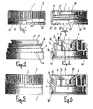
- Figs. 3 and 4 the body 7 of the cap is illustrated in a shape that is almost a hollow cylinder, which has in the upper central zone a pouring spout 8, with drip-stopping rim 9, inside which there is a bowl 10 with closed bottom with the function of anti-bubble making, sustained by radial beams 11.
- a ring-shaped conformation is envisaged, inside which there is a ring groove 12, aimed at receiving by pressure the upper mouth of the container 13; this ring conformation has on its upper external part a serration 14 turned upwards, corresponding to the serration 4 of the lid 1.
- a thread is envisaged corresponding to the thread 6 of the lid 1.
- the cap After filling of the container 13 with the liquid, the cap is mounted on the container 13 through axial thrust so that the cap itself blocks by snap, through the ring groove 12 of joint on the mouth of the container itself.
- Adoption of the guarantee ring with different heights, or with constant height, depends on the functionality and dimensions of the cap, as well as its preferred external aspect.
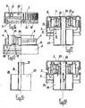
- the vertical radial beams 11 of support and fixing for the anti-bubble forming bowl 10 may be substituted by two cylindrical sectors 18, 19 on a vertical axis that are divided from one another by two opposing slits 20, 21 of different dimensions, one larger and one smaller.
- the cap described here is also used on the basis of a further solution, as a measuring device of liquid, as shown in the figures from 14 to 18, in which the parts shared with the previous solutions are indicated with the same reference numbers.
- Fig. 16 shows the measuring device formed of a shell 25 with closed bottom and open top and formed of a vertical cannula 26 grafted onto the centre of the bottom of the shell and coming out towards the top until it arrives below the lid 1 of the cap.
- a double external ring ridge 27 On the tip of said cannula 26, appears a double external ring ridge 27, which may be hooked up by the ring prominence 22 of the lid 1.
- Said cannula 26 is forced inside the penetrating hole 24 of the bowl 23 and is held in place by means of its upper ring ridge 27.
- the shell 25 fills with liquid, according to the flow indicated with the arrow R of Fig. 17 , while when one unscrews the lid 1, the ring prominence 22 of the lid 1 acts on the external ridge 27 of the cannula 26 and provokes the raising of the shell 25 according to the arrow S of Fig. 18 , until it rests with its upper edge 28 against the lower ring expansion 29 of the body 7.
- the liquid of the shell in dosed quantity is separated from the remaining liquid in the container 13 and after having removed the lid, one can pour the dosed liquid according to the arrow T of Fig. 18 . After pouring of the dosed quantity, one screws the lid 1 back on which causes the shell 25 to move down due to thrust on the cannula 27, in order to perform a new action of dosing.
Landscapes
- Engineering & Computer Science (AREA)
- Mechanical Engineering (AREA)
- Closures For Containers (AREA)
- Cartons (AREA)
- Closing Of Containers (AREA)
Claims (6)
- Ein Behälterverschluss, in dem der genannte Verschluss aus einem Deckel (1) und einem Körper mit einem durch ein Aufschrauben des Deckels (1) brechbarem Siegel geformt ist, wobei der Deckel (1) auf den Körper (7) aufgeschraubt und der Körper (7) durch einen axialen Druck auf den Behälter (13) aufgeschnappt wird, der genannte Deckel (1) mit einem Versiegelungsprofil (5) der Ausgussmündung (8) und einem Gewinde (6) für die Montage auf den Verschlusskörper (7) versehen ist, der Verschlusskörper (7) mit einer zentralen Ausgussmündung (8) mit einem oberen Tropfenschutzrand (9) ausgestattet ist, der Körper (7) an seiner Unterseite eine für einen Schnappeingriff mit der oberen Mündung des Behälters (13) geeignete ringförmige Ausbildung (12) besitzt und der Verschlusskörper (7) ein dem Gewinde (6) des Deckels (1) entsprechendes Gewinde aufweist, dadurch gekennzeichnet dass der Deckel (1) in seinem unteren Bereich mit einem über brechbare Füßchen (3) mit dem Deckel verbundenen Garantiering (2, 2', 15) ausgerüstet ist, der genannte Garantiering (2, 2', 15) in seinem unteren Bereich mit einer gezackten Verzahnung (4) und der Verschlusskörper (7) mit einer Mulde (10) mit einem als Brodelschutz dienenden verschlossenen Boden ausgerüstet ist, wobei die genannte Mulde (10) durch radiale Querträger (11) gehalten und der Verschlusskörper (7) im oberen Bereich der ringförmigen Ausbildung (12) äußerlich mit einer nach oben gerichteten gezackten Verzahnung(14) versehen ist, die einer gezackten, nach unten gerichteten gezackten Verzahnung (4) des Garantieringes (2, 2', 15) entspricht, sodass zum Ausgießen des Inhalts der Deckel (1) ausgeschraubt und dadurch, als Gegenstück zu den von den gezackten Verzahnungen (4, 14) hervorgerufenen Bewegungen (4, 14) ein Brechen der brechbaren Füßchen (3) und des Garantierings (2, 2', 15) verursacht wird, sodass ein Ausgießen von unbestimmten Mengen von Flüssigkeit bewerkstelligt werden kann.
- Ein Verschluss nach Anspruch 2, dadurch gekennzeichnet dass der Garantiering (2, 2') verschiedene Höhen oder eine einzige Höhe (15) aufweisen kann.
- Ein Verschluss nach Anspruch 1, dadurch gekennzeichnet dass die an verschiedenen Höhen (2, 2') angeordneten Teile des Garantierings Abschnitte mit veränderlichen Winkeln von 180/180°, 270/90°, 240/120° usw. abdecken können.
- Ein Verschluss nach Anspruch 1, dadurch gekennzeichnet dass der Garantiering (2, 2', 15) eine quer-verlaufende Unterbrechung (16) gegenüber den freien, mit einem brechbaren Füßchen (17) untereinander verbundenen Enden des Ringes aufweist, um bei Ausschrauben des Deckels den Bruch des genannten Ringes zu begünstigen.
- Ein Verschluss nach Anspruch 1, dadurch gekennzeichnet dass die Mulde (10) von zwei zylindrischen, mit einer senkrechten Achse versehenen Abschnitten getragen wird, die radiale Querträger (11) ersetzen, wobei die genannten Abschnitte (18, 19) durch einander gegenüberliegende, offene Schlitze (20, 21) verschiedener Größe, einem oberen und einem unteren voneinander getrennt sind, sodass man beim Umkehren des Behälters um 180° verschiedene, vorbestimmte Ausflussmengen erzielen kann.
- Ein Behälterverschluss, wobei der genannte Verschluss aus einem Deckel (1) und einem Körper (7) mit einem durch Ausschrauben de Deckels (1) brechbaren Siegel besteht, wobei der Deckel (1) auf den Körper aufgeschraubt und der Körper (7) durch einen axialen Druck auf die Mündung des Behälters (13) aufgeschnappt wird, der genannte Deckel (1) ein die Ausgussmündung (8) versiegelbares Profil und ein Gewinde (6) für die Montage auf den Verschlusskörper (7) hat, der Verschlusskörper (7) eine zentrale, mit einem Tropfenschutzrand (9) versehenen Ausgussöffnung 8) aufweist, der Verschlusskörper (7) in seinem unteren Bereich eine ringförmige Ausbildung (12) hat, die eine obere Öffnung des Behälters (13) mit einer Schnappbewegung aufnehmen kann, und der Verschlusskörper (7) ein dem Gewinde (6) des Deckels (1) entsprechendes Gewinde aufweist, dadurch gekennzeichnet dass der Deckel (1) in seinem unteren Bereich mit einem über brechbare Füßchen (3) mit dem Deckel selbst verbundenen Garantiering (2, 2'; 15) ausgerüstet ist, wobei der genannte Garantiering auf verschiedenen Höhen angeordnete Teile haben oder eine einzige fixe Höhe aufweisen kann, der genannte Garantiering (2, 2', 15) in seinem unteren Bereich mit einer gezackten Verzahnung (4), und der genannte Deckel (1) in seinem Inneren mit einer kreisförmig vorstehenden Stufe (22) ausgerüstet ist und der Verschlusskörper (7) eine mit einem zentralen, durchgehenden Loch versehene Brodel-Schutzmulde (23) aufweist, wobei die genannte Mulde (23) von radialen Querträgern (11) gehalten wird und der Verschlusskörper im oberen Bereich der ringförmigen Ausbildung (12) äußerlich mit einer gezackten, nach oben gerichteten und einer der nach unten gerichteten Verzahnung (4) entsprechenden Verzahnung (14) des Garantierings (2, 2', 15) versehen ist, der Verschluss ein von einer Schutzhülle (25) mit geschlossenem Boden und offenen Oberteil und einer senkrechten, im Zentrum des Bodens der Hülle (25) eingreifenden und nach oben bis unter den Deckel hinausragenden Kanüle (26) geformtes Dosierungsgerät aufweist, die genannte Kanüle (26) an ihrem obersten Ende eine ringförmige äußere Stufe (27) aufweist, in welche die ringförmige innere Stufe (22) des Deckels (1) ein- oder ausgreift, die genannte Kanüle (26) in das Loch (24) der Brodel-Schutzmulde (23) hineingezwängt wird und die genannte Hülle (25) mit einem oberen Rand (28) ausgerüstet ist, der sich über eine ringförmige Aufwölbung (29) des Körpers (7) schließen kann, sodass die genannte Hülle bei einem Schütteln des Behälters (13) eine dosierte Flüssigkeitsmenge empfängt, durch Ausschrauben und Entfernen des Deckels (1) angehoben wird, zwischen ihrem Rand (28) und die ringförmige Wölbung (29) des Körpers (7) eine Versiegelung bildet und ein Ausgießen einer oder mehrerer dosierter Flüssigkeitsmengen erlaubt.
Applications Claiming Priority (2)
| Application Number | Priority Date | Filing Date | Title |
|---|---|---|---|
| IT000080A ITGE20030080A1 (it) | 2003-10-15 | 2003-10-15 | Tappo per contenitori con sigillo rompibile con la |
| ITGE20030080 | 2003-10-15 |
Publications (3)
| Publication Number | Publication Date |
|---|---|
| EP1535855A1 EP1535855A1 (de) | 2005-06-01 |
| EP1535855B1 true EP1535855B1 (de) | 2010-04-14 |
| EP1535855B8 EP1535855B8 (de) | 2010-07-14 |
Family
ID=34452245
Family Applications (1)
| Application Number | Title | Priority Date | Filing Date |
|---|---|---|---|
| EP04019260A Expired - Lifetime EP1535855B8 (de) | 2003-10-15 | 2004-08-13 | Verschluss für Behälter mit Originalitätssicherungselement |
Country Status (6)
| Country | Link |
|---|---|
| EP (1) | EP1535855B8 (de) |
| AT (1) | ATE464240T1 (de) |
| DE (1) | DE602004026529D1 (de) |
| ES (1) | ES2344642T3 (de) |
| IT (1) | ITGE20030080A1 (de) |
| PT (1) | PT1535855E (de) |
Families Citing this family (1)
| Publication number | Priority date | Publication date | Assignee | Title |
|---|---|---|---|---|
| ITMI20120931A1 (it) * | 2012-05-29 | 2013-11-30 | Guala Closures Spa | Versatore. |
Family Cites Families (11)
| Publication number | Priority date | Publication date | Assignee | Title |
|---|---|---|---|---|
| DE2456931A1 (de) * | 1974-12-02 | 1976-08-12 | Mauser Kg | Schraubkappe |
| FR2492774A1 (fr) * | 1980-10-29 | 1982-04-30 | Bouchons Plastiques | Bec verseur pour recipient ou analogue agence pour eviter les variations de debit et dispositif d'obturation pourvu d'un tel bec verseur |
| FR2565208B1 (fr) * | 1984-06-04 | 1987-04-03 | Rical Sa | Ensemble verseur et capsule de bouchage inviolable |
| FR2577891B1 (fr) * | 1985-02-22 | 1987-11-20 | Bormioli Metalplast Spa | Capsule en matiere plastique, en deux pieces, pourvue de bande d'inviolabilite, notamment pour bouteilles |
| GB2172273B (en) * | 1985-03-14 | 1988-12-21 | Bormioli Metalplast Spa | Plastic cap in two parts incorporating a breakable seal, for bottles in particular |
| DK158289A (da) * | 1988-04-13 | 1989-10-14 | Colgate Palmolive Co | Vaeskebeholder med doseringsindretning |
| IT1247089B (it) * | 1991-05-29 | 1994-12-12 | Taplast | Dispostivo dosatore per liquidi |
| US5584420A (en) * | 1995-03-29 | 1996-12-17 | Awada; Hassan | Reusable and accurately pre-measured liquid dispenser |
| DE29603551U1 (de) * | 1996-02-27 | 1996-05-30 | Friedrich Sanner GmbH & Co KG Spritzgußwerk, 64625 Bensheim | Flüssigkeits-Behälter mit Dosiervorrichtung |
| KR100639480B1 (ko) * | 1998-05-22 | 2006-10-26 | 가부시키가이샤 요시노 고교쇼 | 액 주출 용기의 내측 마개와 캡 및 그 캡을 내측 마개에 부착하는데 이용하는 지그 |
| EP1280711B8 (de) * | 2000-03-31 | 2006-03-22 | Ab Cerbo | Schraubverschluss |
-
2003
- 2003-10-15 IT IT000080A patent/ITGE20030080A1/it unknown
-
2004
- 2004-08-13 PT PT04019260T patent/PT1535855E/pt unknown
- 2004-08-13 EP EP04019260A patent/EP1535855B8/de not_active Expired - Lifetime
- 2004-08-13 DE DE602004026529T patent/DE602004026529D1/de not_active Expired - Lifetime
- 2004-08-13 ES ES04019260T patent/ES2344642T3/es not_active Expired - Lifetime
- 2004-08-13 AT AT04019260T patent/ATE464240T1/de not_active IP Right Cessation
Also Published As
| Publication number | Publication date |
|---|---|
| EP1535855A1 (de) | 2005-06-01 |
| EP1535855B8 (de) | 2010-07-14 |
| DE602004026529D1 (de) | 2010-05-27 |
| ITGE20030080A1 (it) | 2005-04-16 |
| PT1535855E (pt) | 2010-07-19 |
| ATE464240T1 (de) | 2010-04-15 |
| ES2344642T3 (es) | 2010-09-02 |
Similar Documents
| Publication | Publication Date | Title |
|---|---|---|
| EP4058374B1 (de) | Verschluss für einen behälter und behälter mit einem solchen verschluss | |
| US9187219B2 (en) | Pour lip closure with drain back | |
| US4128189A (en) | Device for improving the pourability of fluids and also forming an improved closure for a container of such fluids | |
| RU2493075C2 (ru) | Укупорочное устройство с крышкой, уменьшающей утечку | |
| US5261569A (en) | Squeezable container for liquid material having a detachable measuring cap | |
| KR970001761Y1 (ko) | 과립상 재료의 분배 장치 | |
| US4802597A (en) | Plastic stopper for a container, with a measuring cup that serves as a cap | |
| CA2721419C (en) | Dispensing cap for beverage container | |
| RU2397932C2 (ru) | Укупорочный узел для емкости | |
| EP2473418A1 (de) | Behälterverschlussanordnung | |
| CA2378290A1 (en) | Dispensing cap with internal measuring chamber | |
| US20080230573A1 (en) | Vessel | |
| EP2899135A1 (de) | Vorrichtung zum ausgiessen einer in einem behälter enthaltenen flüssigkeit | |
| US7775400B2 (en) | Rotatable, reclosable closure | |
| EP1535855A1 (de) | Verschluss für Behälter mit Originalitätssicherungselement | |
| GB2206558A (en) | Pouring insert and dosing cap for a container | |
| JP6129030B2 (ja) | 注出容器 | |
| JP5611543B2 (ja) | 液だまり防止キャップ | |
| JP7051277B2 (ja) | ヒンジキャップ | |
| JP4140678B2 (ja) | ヒンジキャップ | |
| JP7387229B2 (ja) | ヒンジキャップ | |
| JPH037312Y2 (de) | ||
| JP2004210354A (ja) | 容器 | |
| EP0635435A1 (de) | Ausgabeverschluss mit Ausgiesser | |
| RU81166U1 (ru) | Закупоривающее устройство для бутылки с жидкостью |
Legal Events
| Date | Code | Title | Description |
|---|---|---|---|
| PUAI | Public reference made under article 153(3) epc to a published international application that has entered the european phase |
Free format text: ORIGINAL CODE: 0009012 |
|
| AK | Designated contracting states |
Kind code of ref document: A1 Designated state(s): AT BE BG CH CY CZ DE DK EE ES FI FR GB GR HU IE IT LI LU MC NL PL PT RO SE SI SK TR |
|
| AX | Request for extension of the european patent |
Extension state: AL HR LT LV MK |
|
| 17P | Request for examination filed |
Effective date: 20051129 |
|
| AKX | Designation fees paid |
Designated state(s): AT BE BG CH CY CZ DE DK EE ES FI FR GB GR HU IE IT LI LU MC NL PL PT RO SE SI SK TR |
|
| GRAP | Despatch of communication of intention to grant a patent |
Free format text: ORIGINAL CODE: EPIDOSNIGR1 |
|
| GRAS | Grant fee paid |
Free format text: ORIGINAL CODE: EPIDOSNIGR3 |
|
| GRAA | (expected) grant |
Free format text: ORIGINAL CODE: 0009210 |
|
| AK | Designated contracting states |
Kind code of ref document: B1 Designated state(s): AT BE BG CH CY CZ DE DK EE ES FI FR GB GR HU IE IT LI LU MC NL PL PT RO SE SI SK TR |
|
| REG | Reference to a national code |
Ref country code: GB Ref legal event code: FG4D |
|
| REG | Reference to a national code |
Ref country code: CH Ref legal event code: EP |
|
| REG | Reference to a national code |
Ref country code: IE Ref legal event code: FG4D |
|
| REF | Corresponds to: |
Ref document number: 602004026529 Country of ref document: DE Date of ref document: 20100527 Kind code of ref document: P |
|
| RAP2 | Party data changed (patent owner data changed or rights of a patent transferred) |
Owner name: FRATELLI ROSSI SRL |
|
| REG | Reference to a national code |
Ref country code: PT Ref legal event code: SC4A Free format text: AVAILABILITY OF NATIONAL TRANSLATION Effective date: 20100712 |
|
| REG | Reference to a national code |
Ref country code: NL Ref legal event code: VDEP Effective date: 20100414 |
|
| RAP2 | Party data changed (patent owner data changed or rights of a patent transferred) |
Owner name: INVAT S.R.L. CON SOCIO UNICO |
|
| REG | Reference to a national code |
Ref country code: ES Ref legal event code: FG2A Ref document number: 2344642 Country of ref document: ES Kind code of ref document: T3 |
|
| REG | Reference to a national code |
Ref country code: GR Ref legal event code: EP Ref document number: 20100401626 Country of ref document: GR |
|
| REG | Reference to a national code |
Ref country code: FR Ref legal event code: CD |
|
| PG25 | Lapsed in a contracting state [announced via postgrant information from national office to epo] |
Ref country code: NL Free format text: LAPSE BECAUSE OF FAILURE TO SUBMIT A TRANSLATION OF THE DESCRIPTION OR TO PAY THE FEE WITHIN THE PRESCRIBED TIME-LIMIT Effective date: 20100414 Ref country code: SE Free format text: LAPSE BECAUSE OF FAILURE TO SUBMIT A TRANSLATION OF THE DESCRIPTION OR TO PAY THE FEE WITHIN THE PRESCRIBED TIME-LIMIT Effective date: 20100414 |
|
| PG25 | Lapsed in a contracting state [announced via postgrant information from national office to epo] |
Ref country code: FI Free format text: LAPSE BECAUSE OF FAILURE TO SUBMIT A TRANSLATION OF THE DESCRIPTION OR TO PAY THE FEE WITHIN THE PRESCRIBED TIME-LIMIT Effective date: 20100414 Ref country code: AT Free format text: LAPSE BECAUSE OF FAILURE TO SUBMIT A TRANSLATION OF THE DESCRIPTION OR TO PAY THE FEE WITHIN THE PRESCRIBED TIME-LIMIT Effective date: 20100414 Ref country code: SI Free format text: LAPSE BECAUSE OF FAILURE TO SUBMIT A TRANSLATION OF THE DESCRIPTION OR TO PAY THE FEE WITHIN THE PRESCRIBED TIME-LIMIT Effective date: 20100414 |
|
| PG25 | Lapsed in a contracting state [announced via postgrant information from national office to epo] |
Ref country code: CY Free format text: LAPSE BECAUSE OF FAILURE TO SUBMIT A TRANSLATION OF THE DESCRIPTION OR TO PAY THE FEE WITHIN THE PRESCRIBED TIME-LIMIT Effective date: 20100421 Ref country code: PL Free format text: LAPSE BECAUSE OF FAILURE TO SUBMIT A TRANSLATION OF THE DESCRIPTION OR TO PAY THE FEE WITHIN THE PRESCRIBED TIME-LIMIT Effective date: 20100414 |
|
| PG25 | Lapsed in a contracting state [announced via postgrant information from national office to epo] |
Ref country code: DK Free format text: LAPSE BECAUSE OF FAILURE TO SUBMIT A TRANSLATION OF THE DESCRIPTION OR TO PAY THE FEE WITHIN THE PRESCRIBED TIME-LIMIT Effective date: 20100414 Ref country code: EE Free format text: LAPSE BECAUSE OF FAILURE TO SUBMIT A TRANSLATION OF THE DESCRIPTION OR TO PAY THE FEE WITHIN THE PRESCRIBED TIME-LIMIT Effective date: 20100414 |
|
| PLBE | No opposition filed within time limit |
Free format text: ORIGINAL CODE: 0009261 |
|
| STAA | Information on the status of an ep patent application or granted ep patent |
Free format text: STATUS: NO OPPOSITION FILED WITHIN TIME LIMIT |
|
| PG25 | Lapsed in a contracting state [announced via postgrant information from national office to epo] |
Ref country code: CZ Free format text: LAPSE BECAUSE OF FAILURE TO SUBMIT A TRANSLATION OF THE DESCRIPTION OR TO PAY THE FEE WITHIN THE PRESCRIBED TIME-LIMIT Effective date: 20100414 Ref country code: RO Free format text: LAPSE BECAUSE OF FAILURE TO SUBMIT A TRANSLATION OF THE DESCRIPTION OR TO PAY THE FEE WITHIN THE PRESCRIBED TIME-LIMIT Effective date: 20100414 Ref country code: SK Free format text: LAPSE BECAUSE OF FAILURE TO SUBMIT A TRANSLATION OF THE DESCRIPTION OR TO PAY THE FEE WITHIN THE PRESCRIBED TIME-LIMIT Effective date: 20100414 Ref country code: BE Free format text: LAPSE BECAUSE OF FAILURE TO SUBMIT A TRANSLATION OF THE DESCRIPTION OR TO PAY THE FEE WITHIN THE PRESCRIBED TIME-LIMIT Effective date: 20100414 |
|
| 26N | No opposition filed |
Effective date: 20110117 |
|
| PG25 | Lapsed in a contracting state [announced via postgrant information from national office to epo] |
Ref country code: IT Free format text: LAPSE BECAUSE OF FAILURE TO SUBMIT A TRANSLATION OF THE DESCRIPTION OR TO PAY THE FEE WITHIN THE PRESCRIBED TIME-LIMIT Effective date: 20100414 Ref country code: MC Free format text: LAPSE BECAUSE OF NON-PAYMENT OF DUE FEES Effective date: 20100831 |
|
| REG | Reference to a national code |
Ref country code: CH Ref legal event code: PL |
|
| GBPC | Gb: european patent ceased through non-payment of renewal fee |
Effective date: 20100813 |
|
| PG25 | Lapsed in a contracting state [announced via postgrant information from national office to epo] |
Ref country code: CH Free format text: LAPSE BECAUSE OF NON-PAYMENT OF DUE FEES Effective date: 20100831 Ref country code: LI Free format text: LAPSE BECAUSE OF NON-PAYMENT OF DUE FEES Effective date: 20100831 |
|
| REG | Reference to a national code |
Ref country code: DE Ref legal event code: R119 Ref document number: 602004026529 Country of ref document: DE Effective date: 20110301 |
|
| PG25 | Lapsed in a contracting state [announced via postgrant information from national office to epo] |
Ref country code: DE Free format text: LAPSE BECAUSE OF NON-PAYMENT OF DUE FEES Effective date: 20110301 Ref country code: IE Free format text: LAPSE BECAUSE OF NON-PAYMENT OF DUE FEES Effective date: 20100813 |
|
| PG25 | Lapsed in a contracting state [announced via postgrant information from national office to epo] |
Ref country code: GB Free format text: LAPSE BECAUSE OF NON-PAYMENT OF DUE FEES Effective date: 20100813 |
|
| PG25 | Lapsed in a contracting state [announced via postgrant information from national office to epo] |
Ref country code: HU Free format text: LAPSE BECAUSE OF FAILURE TO SUBMIT A TRANSLATION OF THE DESCRIPTION OR TO PAY THE FEE WITHIN THE PRESCRIBED TIME-LIMIT Effective date: 20101015 Ref country code: BG Free format text: LAPSE BECAUSE OF FAILURE TO SUBMIT A TRANSLATION OF THE DESCRIPTION OR TO PAY THE FEE WITHIN THE PRESCRIBED TIME-LIMIT Effective date: 20100414 Ref country code: LU Free format text: LAPSE BECAUSE OF NON-PAYMENT OF DUE FEES Effective date: 20100813 |
|
| PG25 | Lapsed in a contracting state [announced via postgrant information from national office to epo] |
Ref country code: TR Free format text: LAPSE BECAUSE OF FAILURE TO SUBMIT A TRANSLATION OF THE DESCRIPTION OR TO PAY THE FEE WITHIN THE PRESCRIBED TIME-LIMIT Effective date: 20100414 |
|
| PG25 | Lapsed in a contracting state [announced via postgrant information from national office to epo] |
Ref country code: BG Free format text: LAPSE BECAUSE OF FAILURE TO SUBMIT A TRANSLATION OF THE DESCRIPTION OR TO PAY THE FEE WITHIN THE PRESCRIBED TIME-LIMIT Effective date: 20100714 |
|
| REG | Reference to a national code |
Ref country code: FR Ref legal event code: PLFP Year of fee payment: 13 |
|
| REG | Reference to a national code |
Ref country code: FR Ref legal event code: PLFP Year of fee payment: 14 |
|
| REG | Reference to a national code |
Ref country code: FR Ref legal event code: PLFP Year of fee payment: 15 |
|
| PGFP | Annual fee paid to national office [announced via postgrant information from national office to epo] |
Ref country code: ES Payment date: 20230905 Year of fee payment: 20 |
|
| PGFP | Annual fee paid to national office [announced via postgrant information from national office to epo] |
Ref country code: PT Payment date: 20230724 Year of fee payment: 20 Ref country code: GR Payment date: 20230720 Year of fee payment: 20 Ref country code: FR Payment date: 20230718 Year of fee payment: 20 |
|
| REG | Reference to a national code |
Ref country code: ES Ref legal event code: FD2A Effective date: 20240826 |
|
| PG25 | Lapsed in a contracting state [announced via postgrant information from national office to epo] |
Ref country code: PT Free format text: LAPSE BECAUSE OF EXPIRATION OF PROTECTION Effective date: 20240822 |
|
| PG25 | Lapsed in a contracting state [announced via postgrant information from national office to epo] |
Ref country code: ES Free format text: LAPSE BECAUSE OF EXPIRATION OF PROTECTION Effective date: 20240814 |
|
| PG25 | Lapsed in a contracting state [announced via postgrant information from national office to epo] |
Ref country code: PT Free format text: LAPSE BECAUSE OF EXPIRATION OF PROTECTION Effective date: 20240822 Ref country code: ES Free format text: LAPSE BECAUSE OF EXPIRATION OF PROTECTION Effective date: 20240814 |