EP4058374B1 - Verschluss für einen behälter und behälter mit einem solchen verschluss - Google Patents
Verschluss für einen behälter und behälter mit einem solchen verschluss Download PDFInfo
- Publication number
- EP4058374B1 EP4058374B1 EP19802163.6A EP19802163A EP4058374B1 EP 4058374 B1 EP4058374 B1 EP 4058374B1 EP 19802163 A EP19802163 A EP 19802163A EP 4058374 B1 EP4058374 B1 EP 4058374B1
- Authority
- EP
- European Patent Office
- Prior art keywords
- opening
- spout
- closure
- flip
- axis
- Prior art date
- Legal status (The legal status is an assumption and is not a legal conclusion. Google has not performed a legal analysis and makes no representation as to the accuracy of the status listed.)
- Active
Links
Images


Classifications
-
- B—PERFORMING OPERATIONS; TRANSPORTING
- B65—CONVEYING; PACKING; STORING; HANDLING THIN OR FILAMENTARY MATERIAL
- B65D—CONTAINERS FOR STORAGE OR TRANSPORT OF ARTICLES OR MATERIALS, e.g. BAGS, BARRELS, BOTTLES, BOXES, CANS, CARTONS, CRATES, DRUMS, JARS, TANKS, HOPPERS, FORWARDING CONTAINERS; ACCESSORIES, CLOSURES, OR FITTINGS THEREFOR; PACKAGING ELEMENTS; PACKAGES
- B65D47/00—Closures with filling and discharging, or with discharging, devices
- B65D47/04—Closures with discharging devices other than pumps
- B65D47/32—Closures with discharging devices other than pumps with means for venting
-
- B—PERFORMING OPERATIONS; TRANSPORTING
- B65—CONVEYING; PACKING; STORING; HANDLING THIN OR FILAMENTARY MATERIAL
- B65D—CONTAINERS FOR STORAGE OR TRANSPORT OF ARTICLES OR MATERIALS, e.g. BAGS, BARRELS, BOTTLES, BOXES, CANS, CARTONS, CRATES, DRUMS, JARS, TANKS, HOPPERS, FORWARDING CONTAINERS; ACCESSORIES, CLOSURES, OR FITTINGS THEREFOR; PACKAGING ELEMENTS; PACKAGES
- B65D47/00—Closures with filling and discharging, or with discharging, devices
- B65D47/04—Closures with discharging devices other than pumps
- B65D47/06—Closures with discharging devices other than pumps with pouring spouts or tubes; with discharge nozzles or passages
- B65D47/08—Closures with discharging devices other than pumps with pouring spouts or tubes; with discharge nozzles or passages having articulated or hinged closures
- B65D47/0804—Closures with discharging devices other than pumps with pouring spouts or tubes; with discharge nozzles or passages having articulated or hinged closures integrally formed with the base element provided with the spout or discharge passage
- B65D47/0809—Closures with discharging devices other than pumps with pouring spouts or tubes; with discharge nozzles or passages having articulated or hinged closures integrally formed with the base element provided with the spout or discharge passage and elastically biased towards both the open and the closed positions
-
- B—PERFORMING OPERATIONS; TRANSPORTING
- B65—CONVEYING; PACKING; STORING; HANDLING THIN OR FILAMENTARY MATERIAL
- B65D—CONTAINERS FOR STORAGE OR TRANSPORT OF ARTICLES OR MATERIALS, e.g. BAGS, BARRELS, BOTTLES, BOXES, CANS, CARTONS, CRATES, DRUMS, JARS, TANKS, HOPPERS, FORWARDING CONTAINERS; ACCESSORIES, CLOSURES, OR FITTINGS THEREFOR; PACKAGING ELEMENTS; PACKAGES
- B65D47/00—Closures with filling and discharging, or with discharging, devices
- B65D47/04—Closures with discharging devices other than pumps
- B65D47/06—Closures with discharging devices other than pumps with pouring spouts or tubes; with discharge nozzles or passages
- B65D47/08—Closures with discharging devices other than pumps with pouring spouts or tubes; with discharge nozzles or passages having articulated or hinged closures
- B65D47/0804—Closures with discharging devices other than pumps with pouring spouts or tubes; with discharge nozzles or passages having articulated or hinged closures integrally formed with the base element provided with the spout or discharge passage
- B65D47/0828—Closures with discharging devices other than pumps with pouring spouts or tubes; with discharge nozzles or passages having articulated or hinged closures integrally formed with the base element provided with the spout or discharge passage and elastically biased towards the open position only
-
- B—PERFORMING OPERATIONS; TRANSPORTING
- B65—CONVEYING; PACKING; STORING; HANDLING THIN OR FILAMENTARY MATERIAL
- B65D—CONTAINERS FOR STORAGE OR TRANSPORT OF ARTICLES OR MATERIALS, e.g. BAGS, BARRELS, BOTTLES, BOXES, CANS, CARTONS, CRATES, DRUMS, JARS, TANKS, HOPPERS, FORWARDING CONTAINERS; ACCESSORIES, CLOSURES, OR FITTINGS THEREFOR; PACKAGING ELEMENTS; PACKAGES
- B65D47/00—Closures with filling and discharging, or with discharging, devices
- B65D47/40—Closures with filling and discharging, or with discharging, devices with drip catchers or drip-preventing means
-
- B—PERFORMING OPERATIONS; TRANSPORTING
- B65—CONVEYING; PACKING; STORING; HANDLING THIN OR FILAMENTARY MATERIAL
- B65D—CONTAINERS FOR STORAGE OR TRANSPORT OF ARTICLES OR MATERIALS, e.g. BAGS, BARRELS, BOTTLES, BOXES, CANS, CARTONS, CRATES, DRUMS, JARS, TANKS, HOPPERS, FORWARDING CONTAINERS; ACCESSORIES, CLOSURES, OR FITTINGS THEREFOR; PACKAGING ELEMENTS; PACKAGES
- B65D2205/00—Venting means
- B65D2205/02—Venting holes
-
- B—PERFORMING OPERATIONS; TRANSPORTING
- B65—CONVEYING; PACKING; STORING; HANDLING THIN OR FILAMENTARY MATERIAL
- B65D—CONTAINERS FOR STORAGE OR TRANSPORT OF ARTICLES OR MATERIALS, e.g. BAGS, BARRELS, BOTTLES, BOXES, CANS, CARTONS, CRATES, DRUMS, JARS, TANKS, HOPPERS, FORWARDING CONTAINERS; ACCESSORIES, CLOSURES, OR FITTINGS THEREFOR; PACKAGING ELEMENTS; PACKAGES
- B65D2251/00—Details relating to container closures
- B65D2251/10—Details of hinged closures
- B65D2251/1008—Means for locking the closure in open position
Definitions
- the present invention relates to a closure for a container and to a system with a container and with such a closure.
- Such closures are typically used for dispensing products contained in a container to which said closure is attached.
- the products to be dispensed are typically fluid products, like e.g. liquids or powdered or granular products, e.g. in the food or beverage area, but also in other applications, e.g. for cleaning substances, detergents or other products.
- the present invention especially relates to a closure having a flip-top lid being attached to a base element by a hinge, while such a flip-top lid can be moved between an opened and closed position, while said flip-top lid is typically rotated around said hinge and around an axis of rotation between its opened and its closed position.
- closures are for example known from EP 2 121 466 B1 .
- US 2012/0074180 A1 discloses a closure according to the preamble of claim 1, with a deck portion having a dispensing opening and one or more vent apertures.
- JP 2009-286465 and DE 78 18 747 U1 disclose further closures known in the art.
- the closure according to the present invention comprises a base element and a flip-top lid attached to said base element by a hinge such that the flip-top lid can be moved between an opened and a closed position.
- said flip-top lid is rotated around an axis of rotation between its opened and its closed position.
- the closure according to the present invention also comprises a spout for dispensing a fluid material, wherein said spout can be a separate element, attachable to or attached to said base element, but said spout can be also integrally formed with said base element.
- said spout has a first dispensing opening and a second dispensing opening, said first and said second dispensing opening being separate from each other and having a different size and/or a different cross-sectional form. Additionally said spout has a vent opening, being separate from both said first and said second dispensing opening and being arranged at least partly between the first and the second opening.
- Such a closure has the advantage that it provides two separate dispensing openings having different dispensing or pouring properties, so that the user can choose one of the dispensing openings, namely the dispensing opening whose dispensing or pouring properties are more suitable for the currently desired dispensing activities.
- the user may therefore select one of the dispensing openings, being for example larger than the other dispensing opening, in case the user wants to dispense a high amount of fluid, so that the dispensing takes less time.
- the user may select a dispensing opening being smaller than the other dispensing opening, in case the user wants to dispense a lower amount of fluid or in case the user wants to more precisely control the amount of fluid to be dispensed.
- vent opening being provided in addition and being positioned at least partly between said first dispensing opening and said second dispensing opening ensures a more controlled dispensing, especially as it at least partly separates the first dispensing opening from the second dispensing opening and as it enables a controlled entry of air through the vent hole and into the container during the dispensing.
- the clear arrangement of the three separate openings therefore not only provides controlled dispensing activities, avoiding potentially undesired turbulences of fluid to be dispensed, securing, at least to a large extent, an essentially laminar dispensing flow of the fluid to be dispensed, but also gives a clear guidance to the user how the dispensing could be correctly controlled, typically by tilting the container in order to pour liquid through one of the two dispensing openings, which can be selected by the direction of tilting the container.
- the clearer separations between each of the openings, the two dispensing openings and the vent opening do further assist the user in how to operate the device and gives a clear guidance as to the amount of tilting of the container being necessary or most convenient to generate a controlled and essentially laminar dispensing of the fluid.
- said first and said second dispensing opening are arranged, in a circumferential direction of the closure, opposite to each other.
- This arrangement has the advantage that the user can simply select the direction into which the system, especially the container with the closure, has to be tilted in order to select one of the dispensing openings, by tilting the container either into one direction or into the opposite direction.
- the tilting directions are therefore separated as far as possible from each other making a clear selection easier for the user and also limiting the potential effects of not exactly matching the correct tilting direction by the user.
- said first opening and said second opening are axially symmetric to an axis being parallel to an axis of rotation, around which the flip-top lid is rotated when being moved between said open and said closed position.
- This axis is preferably not only a horizontal axis being parallel to the axis of rotation of said flip-top lid but also extending through the middle of the closure.
- the closure has a vertical axis or z-axis, extending in a vertical direction.
- this vertical axis or z-axis is also the longitudinal axis of this cylindrically formed base element or skirt.
- the upward direction of this vertical axis or z-axis is the direction where the flip-top lid is positioned, the flip-top lid defining an upper part of the closure, whereas the downward direction of this vertical axis or z-axis is the direction where the base or base element is positioned, defining a lower part of the closure.
- the lower part of the closure is therefore the part of the closure which is attached or attachable to a container, whereas the upper part of the closure is the part of the closure where the flip-top lid is arranged, in opposite side of the closure which is attached or attachable to a container.
- a cross axis or x-axis there are also two horizontal axes, a cross axis or x-axis and a longitudinal axis or y-axis, being normal to each other and being normal to the vertical axis or z-axis, thereby defining a coordinate system.
- the longitudinal axis or y-axis extends through the middle of the closure and through the middle or the center of the hinge, whereas the cross axis or x-axis extends normal thereto.
- said first and said second opening are adapted and positioned such that the main pouring direction or the primary pouring direction of the first opening is positioned opposite to the main pouring direction or the primary pouring direction of the second opening.
- the main or primary pouring direction of the opening is typically the direction into which the container is tilted in order to optimally use the dispensing opening, where it is typically the center of a dispensing opening through which the fluid is dispensed first when tilting the container.
- the pouring directions of the first opening and the second opening are preferably parallel to a plane defined by an axis of rotation, around which the flip-top lid is rotated when being moved between said opened and said closed position and the vertical axis or z-axis of the closure.
- the pouring directions are especially preferably in a direction being in a plane defined by said vertical axis or z-axis and said cross axis or x-axis.
- the middle or center of the hinge defines a 12 o'clock position, in a top view from above the closure downwardly longer vertical axis or z-axis, wherein the first opening and the second opening are arranged such that their center or an axis of symmetry, provided that it is a closure in which said openings are axially symmetric, preferably the cross axis or x-axis, are in a 3 o'clock position and in a 9 o'clock position, respectively.
- said first and said second opening are not only arranged in opposite directions, but also such that the flip-top lid, when being in its opened position, is always at a side position, independent on which of the dispensing opening is used by a user, thereby ensuring that the flip-top lid is not disturbing the dispensing activities and the flow of the fluid to be dispensed.
- the height of the spout is constant over a circumferential angular distance of more than 180°, preferably over a circumferential angular distance of more than 210° or even 240°.
- the spout has a bulge or indentation or a reduced height in an angular position being closest to said hinge, wherein said bulge or indentation or reduced height extends over a circumferential angular distance of at least 30°, preferably over a circumferential angular distance of at least 60° or even of at least 90°.
- a preferred range over which the indentation extends, in a circumferential direction is between 80° and 160°, preferably between 90° and 140°, further preferably between 100° and 130°.
- This specific arrangement has the advantage that the constant height over a large or even the major part of the circumferential area of the closure supports a controlled and especially laminar dispensing flow through each of the dispensing openings, when the device is handled correctly and in case the user selects one of the dispensing openings and dispensing directions, but it also has the advantage that even in case of an incorrect handling of the device, e.g. by a user tilting a container in a direction away from the hinge, with respect to the above-mentioned top view into a 6 o'clock position, the dispensing flow is still kept essentially laminar, while avoiding the dripping of liquid onto the closure, especially onto the neck or other parts of the base element.
- said closure has only one such bulge or indentation, especially in the area being closest to the hinge, in order to ensure the above-mentioned advantages, while otherwise keeping the height of the spout on a constant level, in order to secure a smooth dispensing and laminar flow, both for dispensing through one of the dispensing openings when the container and the closure is utilized in a correct form, but also in case of mishandling of the device by the user, as described above.
- the minimum height of said bulge or indentation is a maximum 70%, preferably at maximum 60% and preferably in a range of 50% to 70% of the maximum height of the spout. It has been found that these values are preferred ranges in order to achieve the above-mentioned advantages in a specifically preferred way.
- the spout comprises a web being arranged within an opening of said spout, while said web bridges said opening of the spout, thereby defining said first opening and said second opening on opposite sides of said web.
- the web itself has an inner opening which defines said vent opening.
- said web is positioned, with respect to the vertical axis or z-axis below or lower than the minimum height of said spout.
- said web is positioned, with respect to its height or its vertical axis or z-axis, on a level or essentially on a level corresponding to a deck or a deck portion of said base element.
- said web is designed and positioned such that an upper plane of said web is positioned below an upper edge of said spout at each angular position of said spout.
- said upper plane of said web is positioned at least 2 mm, preferably at least 3 mm, below an upper edge of said spout at an angular position where said bulge indentation has its minimum height.
- said web comprises an inner extension wall surrounding said vent opening extending from said web into an inward or downward direction.
- This inner extension wall has the advantage of an even more clear separation of the vent opening from the dispensing openings, securing that, even with a not absolutely correct handling of the device by a user, e.g. by tilting the container too strongly, the fluid is only dispensed through one of the dispensing opening, avoiding an entry of the fluid or even a dispensing of the fluid through the vent opening, at least until a certain extent of mishandling of the device.
- the closure provides the base element with the tongue member extending upwardly (in a vertical direction or that direction or at least with a component in said vertical direction or sets direction) from an upper region or an upper plane of said base member, wherein said flip-top lid has a protrusion extending outwardly from said flip-top lid in a direction normal to (or having at least normal component to) the vertical axis or z-axis.
- the tongue and the protrusion are arranged such that they interact with each other, thereby creating a bistable system, in which the flip-top lid is pushed into a direction towards its fully opened position when said flip-top lid is in the predetermined second angular range. This arrangement provides more defined positioning of the flip-top lid, especially in its fully opened position.
- the tongue may even partly extend into said bulge or indentation of said spout, especially when said flip-top lid is in its fully opened position or in a position where the flip-top lid is in its bistable position, where it is pushed into either the fully open position or into the direction of the closed position and only slightly being brought out of bistable position.
- the inventors have found that the selection of sizes of the first and the second opening are working especially preferable in case the larger opening is larger than the smaller opening by a factor of at least 1.5, preferably by a factor of at least 2, further preferably at least by factor 2.5. Furthermore, with respect to the size of the vent opening, the inventors have found that it is especially preferable when the smaller dispensing opening has a size being larger than the size of the vent opening by at least factor 1.2, preferably by at least factor 1.5, further preferably by at least factor 2.
- the curvature of the first opening is different from the curvature of the second opening, especially at radially outward points, preferably in an opposite angular position.
- the curvature of the larger of the first or the second opening is smaller than the curvature of the smaller of the first or the second opening at opposing radially outward positions with respect to a horizontal axis (x-axis) being normal to a vertical axis (z-axis) of said closure. This supports the dispensing or pouring properties of the dispensing openings.
- said flip-top lid has an inner sealing wall, extending from an inner side of said flip- top lid and being arranged and positioned such that it comes into the sealing contact with said spout, preferably with an inner region of said spout, when said flip-top lid is in its closed position, such that both the first and the second opening and the vent opening are sealed by the interaction of said inner sealing wall with said spout.
- an arrangement has the advantage that all openings, including the vent opening, are automatically sealed to the outside when the flip-top lid is in its closed position.
- the above-mentioned bulge or indentation of the spout in the area of or near to the hinge, has the specific advantage that it avoids an early abutting of said inner sealing wall with said spout during the closing movement of said flip-top lid, which is, as explained above, due to the hinge, a rotational movement.
- the sealing properties can therefore be securely maintained, also over a long period of utilization (lifetime) of the closure, with many cycles of opening and closing the flip-top lid.
- the present invention also relates to a system with a container with a closure as described above, wherein said closure is attachable or attached to the container or wherein said closure is integrally formed with the container.
- both said closure and said container comprises fastening means, which can interact with each other.
- the system is manufactured at least partly as a unitary system, e.g. the base element or part of the base element could be integrally formed with a part of the container. It is also possible to create such a system by fastening the closure and the container together by various attachment systems, for example by welding or gluing.
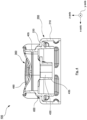
- Fig. 1 shows a perspective view of an embodiment of the closure 100 according to the present invention comprising a base element 200 with a cylindrical skirt 210, a spout element or spout 400 and a flip-top lid 300 being attached to the base element 200 via a hinge 500.
- the flip-top lid 300 is in its fully opened position, so that the spout 400 is free for dispensing a fluid.
- the spout 400 extends with its spout walls 405 beyond the base element 200 and especially above or beyond a deck 220 of the base element 200, while the height of the spout wall 405 is essentially constant or constant over a major part of its circumference, but the spout 400 has a bulge or indentation 490 in an angular position being close to the hinge 500.
- Fig. 2 shows a top view the embodiment as shown in Fig. 1 , from an upper position in a downward direction along the vertical z-axis.
- the inside of the a spout wall 405 of the spout 400 has an opening 480, which is separated into a first dispensing opening 410, a second dispensing opening 420 and a vent opening 430.
- the spout 400 also comprises a web 450, which separates the first dispensing opening 410 fully from the second dispensing opening 420, while the vent opening 430 is provided within the web 450.
- the position of the hinge or the middle or center of the hinge marks a 12 o'clock position, while the center of the first dispensing opening 410 is in the 9 o'clock position and the center of the second dispensing opening 420 is in the 3 o'clock position.
- the web 450 extends essentially along the y axis and separates the first dispensing opening 410, being, in this view, on the left side, from the second dispensing opening 420, being, in this view, on the right side.
- the 3 o'clock position and the 9 o'clock position mark the main or primary pouring directions for the first dispensing opening 410 and the second dispensing opening 420, respectively, which would be a preferred arrangement also for other embodiments.
- both the first dispensing opening 410 and the second dispensing opening 420 are axially symmetric relative to the x-axis, and also this is an arrangement which is preferred also for other embodiments.
- the first dispensing opening 410 is larger than the second dispensing opening 420, and in this specific embodiment the first dispensing opening 410 has a cross-sectional area of about 60 mm 2 , while the second dispensing opening 420 has a cross sectional area of about 24 mm 2 .
- the cross-sectional area of the vent opening 430 is about 16 mm 2 large. While the two dispensing openings 410, 420 always have different sizes, the specific selection of the cross-sectional areas can be adapted to the specific situation in other embodiments.
- the vent opening is always smaller than both the first dispensing opening 410 and the second dispensing opening 420.
- the indentation 490 extends in the area around and from the 12 o'clock position and over an angular distance of about 120°, while the angular area of the spout 400, which has a constant height, extends over an angular distance of about 240°(see also Fig.4 and the corresponding description hereinafter) .
- both the first dispensing opening 410 and the second dispensing opening 420 have an essentially U-form or V-form cross-section, which is very preferable for a controlled pouring or dispensing of liquid, especially in connection with the vent hole 430 provided between the first dispensing opening 410 and the second dispensing opening 420 as well as especially in connection with the web 450 separating these two dispensing openings. While other cross-sectional forms are also possible, this specific U-form or V-form cross-section is preferred, also for and in other embodiments.
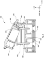
- Fig. 3 shows the embodiment of the closure as shown in Fig. 1 , however in a cross-sectional view.
- the spout 400 is, in this embodiment, a separate element, which is inserted into the base element 200 and secured thereto.
- a spout being integrally formed with the base element.
- the spout wall 405 has, over a majority of its circumference, a constant height h1, measured from the deck 220 of said base element 200, while the spout wall 405 has, in the vicinity of the hinge 500, a bulge or indentation 490.
- the indentation 490 has its minimum height h2 at a position of the circumference of the spout wall 405 being, in a circumferential direction, closest to the hinge 450.
- the indentation 490 extends, in this embodiment, over an angular range of about 130°, while the height of the spout wall 405, measured relative to the deck 220 of the base element 200, increases, from its lowest height h2, at its portion being closest to the hinge element 500, gradually until reaching its maximum height h2, which it then keeps constant over the remaining area or circumferential range of the spout wall 405.
- the spout 400 being a separate element, is inserted into and fixed to the base element 200, in this embodiment by a snap fitting attachment.
- the spout 400 is also integrally formed with the web 450, which comprises the vent hole 430.
- Said web 115 also comprises an inner extension wall 435, which surrounds the vent hole 430.
- This inner extension wall 435 has especially the advantage that liquid to be dispensed is, at least to a certain extent, prevented from entering into the vent hole 430, thereby securing a correct functioning of the closure, even if the potential handling by the user should not be perfect, thereby especially ensuring a proper and laminar dispensing of liquid over broad range.
- Fig. 3 also visualizes an interaction between a tongue 260, extending from a deck 220 of the base element 200 in an upward direction, and the protrusion 360 extending from said flip-top lid 300, essentially in an outward or radially outward direction. Due to the flexibility and elasticity of the tongue 260, the tongue 260 does, in this position of the flip-top lid 300, exerts a force onto said flip-top lid 300, via the projection 360, which pushes or keeps the flip-top lid 300 into its fully opened position.
- Fig. 4 shows a partial cross-sectional view of the embodiment as shown in Fig. 3 along a plane defined by the x-axis and the z-axis, with the flip-top lid 300 being in its fully opened position (therefore a partial cross-sectional view from the left side, when referring to Fig. 3 ).
- the indentation 490 of the spout 400 or of the spout wall 405 is very well visible, with its minimum height in the vicinity of the hinge, and the height gradually increasing in both directions until reaching its maximum height, which is then kept constant, as explained above.
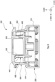
- Fig. 5 shows a cross-sectional view of another embodiment of the closure 100 according to the present invention, while the cross-section is very similar to the presentation of the first embodiment as shown in Fig. 3 , however with the flip-top lid 300 being in an intermediate position, closer to the closed position of the flip-top lid 300.
- This embodiment is very similar to the embodiment shown in the earlier figures, so that the same or similar elements are referred to by the same reference numbers.
- the indentation 490 of the spout wall 405 provides sufficient space for other elements of the flip-top lid 300, especially for an inner sealing wall 320, extending from an inner side of the flip-top lid 300, which avoids, at least until a certain extent, an abutment of said inner sealing wall 320 with parts of the spout wall 405, which avoids wear at these very sensible parts, having a major function for the sealing capabilities of the closure.
- Fig. 6 shows the embodiment as shown in Fig. 5 , however, with the flip-top lid 300 in its fully closed position.
- the inner sealing wall 320 seals against an inner part of the spout wall 405, whereas, in the area of the indentation (490, see especially Fig. 5 ) the sealing wall 320 has a stepped or a cornered portion which seals against the corresponding parts of the spout wall 405.
Landscapes
- Engineering & Computer Science (AREA)
- Mechanical Engineering (AREA)
- Closures For Containers (AREA)
Claims (15)
- Verschluss (100) für einen Behälter mit- einem Grundelement (200),- einem Klappdeckel (300), der durch ein Scharnier (500) so an dem Grundelement (200) angebracht ist, dass der Klappdeckel (300) zwischen einer geöffneten und einer geschlossenen Position bewegt werden kann, wobei der Verschluss (100) einen Ausgießer (400) zur Abgabe eines Fluidmaterials umfasst, wobei der Ausgießer (400) eine erste Abgabeöffnung (410) und eine Belüftungsöffnung (430) aufweist, dadurch gekennzeichnet, dass der Ausgießer (400) ferner eine zweite Abgabeöffnung (420) aufweist, wobei die erste (410) und die zweite Abgabeöffnung (420) voneinander getrennt sind und eine unterschiedliche Größe und/oder eine unterschiedliche Querschnittsform aufweisen,wobei die Belüftungsöffnung (430) sowohl von der ersten Abgabeöffnung (410) als auch der zweiten Abgabeöffnung (420) getrennt ist undwobei die Belüftungsöffnung (430) wenigstens teilweise zwischen der ersten Abgabeöffnung (410) und der zweiten Öffnung (420) angeordnet ist.
- Verschluss (100) nach Anspruch 1, wobei die erste (410) und die zweite Abgabeöffnung (420) in einer Umfangsrichtung des Verschlusses (100) einander gegenüberliegend angeordnet sind,
und/oder
wobei die erste Öffnung (410) und die zweite Öffnung (420) zu einer Achse (X-Achse) achsensymmetrisch sind, die parallel zu einer Drehachse verläuft, um die der Klappdeckel (300) gedreht wird, wenn er zwischen der geöffneten und der geschlossenen Position bewegt wird. - Verschluss (100) nach einem der vorhergehenden Ansprüche, wobei die erste (410) und die zweite Öffnung (420) dafür geeignet und so positioniert sind, dass eine Hauptausgießrichtung der ersten Öffnung (410) einer Hauptausgießrichtung der zweiten Öffnung (420) entgegengesetzt ist, wobei die Ausgießrichtungen der ersten Öffnung (410) und der zweiten Öffnung (420) parallel zu einer Ebene, die von einer Drehachse definiert ist, um die der Klappdeckel (300) gedreht wird, wenn er zwischen der geöffneten und der geschlossenen Position gedreht wird, und einer vertikalen Achse (Z-Achse) des Verschlusses (100) verlaufen.
- Verschluss (100) nach einem der vorhergehenden Ansprüche, wobei in einer Draufsicht von oberhalb des Verschlusses nach unten entlang einer vertikalen Achse (Z-Achse) eine Mitte oder ein Mittelpunkt des Scharniers (500) eine 12-Uhr-Position definiert, wobei die erste Öffnung (410) und die zweite Öffnung (420) so angeordnet sind, dass sich ihr Mittelpunkt oder eine Symmetrieachse in dem Fall, dass die erste und zweite Abgabeöffnung (410, 420) achsensymmetrisch sind, in einer 3-Uhr-Position bzw. einer 9-Uhr-Position befinden.
- Verschluss (100) nach einem der vorhergehenden Ansprüche, wobei eine Höhe (h1) des Ausgießers (400) oder einer Ausgießerwand (405), insbesondere eine Höhe (h1) der Ausgießerwand (405) bezogen auf ein Deck (220) des Grundelements (200), über einen Umfangswinkelabstand von mehr als 180°, vorzugsweise mehr als 200°, vorzugsweise in einem Bereich von 190° bis 240° konstant ist, wobei der Ausgießer (400) eine Wölbung oder Vertiefung (490) oder eine verringerte Höhe in einer Winkel- oder Umfangsposition aufweist, die dem Scharnier (500) am nächsten liegt, wobei sich die Wölbung oder Vertiefung (490) oder verringerte Höhe über einen Umfangswinkelabstand des Ausgießers (400) oder der Ausgießerwand (405) von wenigstens 30°, vorzugsweise über einen Umfangswinkelabstand von wenigstens 60° oder sogar wenigstens 90° erstreckt,wobei vorzugsweise der Verschluss (100) nur eine Wölbung oder Vertiefung (490) aufweist,
und/oder,wobei vorzugsweise die Mindesthöhe (h2) der Wölbung oder Vertiefung (490) höchstens 70 %, vorzugsweise höchstens 60 % beträgt und vorzugsweise in einem Bereich von 50 % bis 70 % einer maximalen Höhe (h1) der Ausgießerwand (405) bezogen auf ein Deck (220) des Grundelements (200) liegt. - Verschluss (100) nach einem der vorhergehenden Ansprüche, wobei der Ausgießer (400) einen Steg (450) umfasst, der innerhalb einer Öffnung (480) des Ausgießers (400) oder innerhalb einer Ausgießerwand (405) des Ausgießers (400) angeordnet ist und die Öffnung (480) der Ausgießerwand (405) oder des Ausgießers (400) überbrückt, wodurch er die erste Öffnung (410) und die zweite Öffnung (420) auf gegenüberliegenden Seiten des Stegs (450) definiert, wobei der Steg (450) selbst eine innere Öffnung aufweist, die die Belüftungsöffnung (430) definiert.
- Verschluss (100) nach Anspruch 6, wobei der Steg (450) in Bezug auf eine vertikale Achse (Z-Achse) unterhalb der Mindesthöhe (h2) der Ausgießerwand (405) positioniert ist,
und/oder
wobei der Steg (450) in Bezug auf eine vertikale Achse (Z-Achse) auf einer Ebene oder im Wesentlichen auf einer Ebene positioniert ist, die einem Deck (220) oder einem Deckteilbereich des Grundelements (200) entspricht. - Verschluss (100) nach Anspruch 6 oder 7, wobei der Steg (450) so ausgelegt und positioniert ist, dass eine obere Ebene des Stegs (450) unterhalb einer Oberkante oder einer Mindesthöhe (h2) der Ausgießerwand (405) oder des Ausgießers (400) an jeder Winkel- oder Umfangsposition des Ausgießers (400) positioniert ist.
- Verschluss (100) nach einem der Ansprüche 6 bis 8, wobei der Steg (450) so ausgelegt und positioniert ist, dass eine obere Ebene des Stegs (450) wenigstens 2 mm, vorzugsweise wenigstens 3 mm unterhalb einer Oberkante der Ausgießerwand (405) oder des Ausgießers (400) in einer Winkel- oder Umfangsposition positioniert ist, wo die Wölbung oder Vertiefung (490) ihre Mindesthöhe (h2) aufweist,
und/oder
wobei der Steg (450) eine Innenerstreckungswand (435) aufweist, die die Belüftungsöffnung (430) umgibt und sich von dem Steg (450) in einer Richtung nach innen oder unten erstreckt. - Verschluss (100) nach einem der vorhergehenden Ansprüche, wobei das Grundelement (200) ein Zungenelement (260) aufweist, das sich von einem oberen Bereich oder einer oberen Ebene des Grundelements (200) in einer Richtung nach oben entlang der vertikalen Achse (Z-Achse) erstreckt, wobei der Klappdeckel (300) einen Vorsprung (360) aufweist, der sich von dem Klappdeckel (300) in einer Richtung, die normal zur vertikalen Achse (Z-Achse) verläuft, nach außen erstreckt, wobei das Zungenelement (260) und der Vorsprung (360) so positioniert und angeordnet sind, dass während einer Bewegung des Klappdeckels (300) zwischen dessen voll geschlossenen und dessen voll geöffneten Position der Vorsprung (360) und das Zungenelement (260) über einen ersten vorbestimmten Winkelbereich der Position des Klappdeckels (300) bezogen auf das Grundelement (200) während dessen Bewegung zwischen dessen voll geschlossenen und dessen voll geöffneten Position miteinander in Kontakt stehen, so dass der Vorsprung (360) in einer Richtung nach innen eine Kraft auf das Zungenelement (260) ausübt und das Zungenelement (260) eine Gegenkraft auf den Vorsprung (360) ausübt, so dass, wenn sich der Klappdeckel (300) innerhalb eines zweiten vorbestimmten Winkelbereichs bezogen auf das Grundelement (200) befindet, die Gegenkraft eine Bewegung des Klappdeckels (300) in einer Richtung hin zu dessen voll geöffneten Position unterstützt, wobei sich das Zungenelement (260) oder eine Außenfläche davon in einem oberen Teil davon vorzugsweise wenigstens teilweise in eine Richtung nach innen erstreckt,
wobei vorzugsweise der Verschluss (100) so ausgelegt und positioniert ist, dass es wenigstens eine Position des Klappdeckels (300) während dessen Bewegung zwischen dessen voll geöffneten und dessen voll geschlossenen Position gibt, in der sich das Zungenelement (260) wenigstens teilweise in die Wölbung oder Vertiefung (490) des Ausgießers (400) erstreckt, insbesondere wenn sich der Klappdeckel (300) in seiner voll geöffneten Position befindet. - Verschluss (100) nach einem der vorhergehenden Ansprüche, wobei die Größe der ersten Öffnung (410) wenigstens um den Faktor 1,5, vorzugsweise wenigstens um den Faktor 2, ferner vorzugsweise wenigstens um den Faktor 2,5 größer als die Größe der zweiten Öffnung (420) ist,
und/oder
wobei die Größe der Belüftungsöffnung (430) kleiner als die Größe jeder der ersten und zweiten Öffnung ist, wobei die kleinere der ersten oder zweiten Öffnung (410, 420) eine Größe aufweist, die wenigstens um den Faktor 1,2, vorzugsweise wenigstens um den Faktor 1,5, ferner vorzugsweise wenigstens um den Faktor 2 größer als die Größe der Belüftungsöffnung (430) ist. - Verschluss (100) nach einem der vorhergehenden Ansprüche, wobei die Krümmung der ersten Öffnung (410) an radial äußeren Punkten von der Krümmung der zweiten Öffnung an radial äußeren Punkten in einer gegenüberliegenden Winkelposition verschieden ist.
- Verschluss (100) nach einem der vorhergehenden Ansprüche, wobei die Krümmung der größeren der ersten oder zweiten Öffnung (410, 420) kleiner als die Krümmung der kleineren der ersten oder zweiten Öffnung (410, 420) an gegenüberliegenden radial äußeren Positionen in Bezug auf eine horizontale Achse (X-Achse) ist, die normal zu einer vertikalen Achse (Z-Achse) des Verschlusses verläuft.
- Verschluss (100) nach einem der vorhergehenden Ansprüche, wobei der Klappdeckel (300) eine Innendichtungswand (320) aufweist, die sich von einer Innenseite des Klappdeckels (300) erstreckt und so angeordnet und positioniert ist, dass sie mit dem Ausgießer (400), vorzugsweise mit einem Innenbereich der Ausgießerwand (405) des Ausgießers (400) in einen Dichtkontakt tritt, wenn sich der Klappdeckel (300) in seiner geschlossenen Position befindet, so dass sowohl die erste als auch die zweite Öffnung (410, 420) und die Belüftungsöffnung (430) durch die Interaktion der Innendichtungswand (320) mit dem Ausgießer (400), insbesondere der Ausgießerwand (405), abgedichtet werden.
- System umfassend einen Behälter und umfassend einen Verschluss nach einem der vorhergehenden Ansprüche, wobei der Verschluss (100) direkt oder indirekt an den Behälter angebracht oder anbringbar ist.
Priority Applications (2)
| Application Number | Priority Date | Filing Date | Title |
|---|---|---|---|
| HUE19802163A HUE062309T2 (hu) | 2019-11-11 | 2019-11-11 | Zárószerkezet egy tartályhoz és ezzel a zárószerkezettel ellátott tartály |
| PL19802163.6T PL4058374T3 (pl) | 2019-11-11 | 2019-11-11 | Zamknięcie do pojemnika i pojemnik z takim zamknięciem |
Applications Claiming Priority (1)
| Application Number | Priority Date | Filing Date | Title |
|---|---|---|---|
| PCT/EP2019/080895 WO2021093936A1 (en) | 2019-11-11 | 2019-11-11 | Vented flip-top closure with two dispensing openings |
Publications (2)
| Publication Number | Publication Date |
|---|---|
| EP4058374A1 EP4058374A1 (de) | 2022-09-21 |
| EP4058374B1 true EP4058374B1 (de) | 2023-04-12 |
Family
ID=68542647
Family Applications (1)
| Application Number | Title | Priority Date | Filing Date |
|---|---|---|---|
| EP19802163.6A Active EP4058374B1 (de) | 2019-11-11 | 2019-11-11 | Verschluss für einen behälter und behälter mit einem solchen verschluss |
Country Status (8)
| Country | Link |
|---|---|
| US (1) | US11964801B1 (de) |
| EP (1) | EP4058374B1 (de) |
| CN (1) | CN114616188B (de) |
| ES (1) | ES2945221T3 (de) |
| HU (1) | HUE062309T2 (de) |
| MX (1) | MX2022005343A (de) |
| PL (1) | PL4058374T3 (de) |
| WO (1) | WO2021093936A1 (de) |
Families Citing this family (17)
| Publication number | Priority date | Publication date | Assignee | Title |
|---|---|---|---|---|
| US12096880B2 (en) | 2022-05-13 | 2024-09-24 | Sharkninja Operating Llc | Flavorant for beverage carbonation system |
| US11647860B1 (en) | 2022-05-13 | 2023-05-16 | Sharkninja Operating Llc | Flavored beverage carbonation system |
| US12213617B2 (en) | 2022-05-13 | 2025-02-04 | Sharkninja Operating Llc | Flavored beverage carbonation process |
| US11751585B1 (en) | 2022-05-13 | 2023-09-12 | Sharkninja Operating Llc | Flavored beverage carbonation system |
| JP2023175062A (ja) * | 2022-05-30 | 2023-12-12 | 三笠産業株式会社 | キャップ |
| US12539500B2 (en) | 2022-08-31 | 2026-02-03 | Sharkninja Operating Llc | Additive containers |
| US12084334B2 (en) | 2022-11-17 | 2024-09-10 | Sharkninja Operating Llc | Ingredient container |
| US12103840B2 (en) | 2022-11-17 | 2024-10-01 | Sharkninja Operating Llc | Ingredient container with sealing valve |
| US11738988B1 (en) | 2022-11-17 | 2023-08-29 | Sharkninja Operating Llc | Ingredient container valve control |
| US11745996B1 (en) | 2022-11-17 | 2023-09-05 | Sharkninja Operating Llc | Ingredient containers for use with beverage dispensers |
| US11634314B1 (en) | 2022-11-17 | 2023-04-25 | Sharkninja Operating Llc | Dosing accuracy |
| USD1091308S1 (en) | 2022-12-23 | 2025-09-02 | Sharkninja Operating Llc | Ingredient container |
| USD1092208S1 (en) | 2022-12-23 | 2025-09-09 | Sharkninja Operating Llc | Cap of ingredient container |
| US11925287B1 (en) | 2023-03-22 | 2024-03-12 | Sharkninja Operating Llc | Additive container with inlet tube |
| US11871867B1 (en) | 2023-03-22 | 2024-01-16 | Sharkninja Operating Llc | Additive container with bottom cover |
| US12116257B1 (en) | 2023-03-22 | 2024-10-15 | Sharkninja Operating Llc | Adapter for beverage dispenser |
| US12005408B1 (en) | 2023-04-14 | 2024-06-11 | Sharkninja Operating Llc | Mixing funnel |
Family Cites Families (20)
| Publication number | Priority date | Publication date | Assignee | Title |
|---|---|---|---|---|
| DE7818747U1 (de) * | 1978-06-22 | 1978-09-28 | Karl Ostmann Fa | Dose mit einem Streuverschluss |
| EP1746041A1 (de) * | 2005-07-19 | 2007-01-24 | CapArtis AG | Drehbarer, wieder verschliessbarer Verschluss |
| CN200945988Y (zh) * | 2006-07-24 | 2007-09-12 | 郭娟 | 导气式容器嘴 |
| WO2008089785A1 (de) | 2007-01-23 | 2008-07-31 | Seaquist-Löffler Kunststoffwerk Gmbh | Verschlussvorrichtung für einen behälter |
| JP5415021B2 (ja) * | 2008-05-30 | 2014-02-12 | 株式会社吉野工業所 | ヒンジキャップ |
| WO2010144776A1 (en) | 2009-06-11 | 2010-12-16 | The J.M. Smucker Company | Dispensing closure |
| CN201849771U (zh) * | 2010-10-30 | 2011-06-01 | 赵汶卿 | 酱油瓶 |
| TWM437829U (en) * | 2012-04-27 | 2012-09-21 | zhen-ji Lin | Multifunctional container cap with fastenable straw |
| JP3177817U (ja) * | 2011-06-07 | 2012-08-16 | 振基 林 | 容器蓋 |
| CN102582936A (zh) * | 2012-03-10 | 2012-07-18 | 苏州雅尔塑业科技有限公司 | 一种控制流量的瓶盖 |
| RU2603594C2 (ru) * | 2012-05-02 | 2016-11-27 | Аптаргруп, Инк. | Укупорочное средство контейнера для вентилируемого выливания через удлиненное отверстие |
| ES1078291Y (es) * | 2012-11-13 | 2013-03-22 | Tanio S A U | Tapón dosificador Bi-flujo |
| CN203006036U (zh) * | 2012-11-22 | 2013-06-19 | 新台塑胶工业股份有限公司 | 密封容器的油嘴盖构造 |
| CN103662358A (zh) * | 2013-11-26 | 2014-03-26 | 南通宝田包装科技有限公司 | 一种可调节使用量的化妆品瓶 |
| DE202014001720U1 (de) * | 2014-02-27 | 2015-03-02 | Gerhard Brugger | Spender |
| CN108202915B (zh) * | 2016-12-19 | 2020-12-04 | 荷兰服饰有限责任公司 | 杯盖 |
| CN108045739A (zh) * | 2017-12-26 | 2018-05-18 | 徐勇 | 一种流量可调节的液体包装瓶盖 |
| CN208181749U (zh) * | 2017-12-29 | 2018-12-04 | 中山市雄略精密模具有限公司 | 一种玻璃瓶翻盖 |
| RU2019120189A (ru) * | 2018-04-05 | 2022-05-05 | Аптар Фрейунг Гмбх | Укупорочное средство для контейнера и контейнер с таким укупорочным средством |
| CN208560248U (zh) * | 2018-06-28 | 2019-03-01 | 精英模具(上海)有限公司 | 一种基于双色注塑的瓶盖结构 |
-
2019
- 2019-11-11 CN CN201980101941.5A patent/CN114616188B/zh active Active
- 2019-11-11 PL PL19802163.6T patent/PL4058374T3/pl unknown
- 2019-11-11 ES ES19802163T patent/ES2945221T3/es active Active
- 2019-11-11 HU HUE19802163A patent/HUE062309T2/hu unknown
- 2019-11-11 EP EP19802163.6A patent/EP4058374B1/de active Active
- 2019-11-11 WO PCT/EP2019/080895 patent/WO2021093936A1/en not_active Ceased
- 2019-11-11 US US17/769,137 patent/US11964801B1/en active Active
- 2019-11-11 MX MX2022005343A patent/MX2022005343A/es unknown
Also Published As
| Publication number | Publication date |
|---|---|
| US20240109693A1 (en) | 2024-04-04 |
| ES2945221T3 (es) | 2023-06-29 |
| MX2022005343A (es) | 2022-05-26 |
| PL4058374T3 (pl) | 2023-08-21 |
| BR112022008553A2 (pt) | 2022-08-09 |
| CN114616188A (zh) | 2022-06-10 |
| CN114616188B (zh) | 2025-07-11 |
| EP4058374A1 (de) | 2022-09-21 |
| US11964801B1 (en) | 2024-04-23 |
| WO2021093936A1 (en) | 2021-05-20 |
| HUE062309T2 (hu) | 2023-10-28 |
Similar Documents
| Publication | Publication Date | Title |
|---|---|---|
| EP4058374B1 (de) | Verschluss für einen behälter und behälter mit einem solchen verschluss | |
| EP3573901B1 (de) | Verschluss für einen behälter und behälter mit solch einem verschluss | |
| RU2277507C2 (ru) | Одноосное укупорочное средство с двойной выдачей | |
| EP3509958B1 (de) | Manipulationssicherer tropfenabgabeverschluss | |
| EP2262691B1 (de) | Kappen-tüllen-kombination | |
| RU2493075C2 (ru) | Укупорочное устройство с крышкой, уменьшающей утечку | |
| JP2002505984A (ja) | 飲料容器 | |
| US7775400B2 (en) | Rotatable, reclosable closure | |
| JP2019131237A (ja) | 混合キャップ | |
| US12534246B2 (en) | Refill system and spout and methods of using the same | |
| EP4455041B1 (de) | Verschluss für einen behälter und behälter mit einem solchen verschluss | |
| US11440710B2 (en) | Self-venting closure | |
| JP2019119522A (ja) | 注出容器 | |
| JP2017137102A (ja) | ヒンジキャップ | |
| GB2394947A (en) | A dispensing cap and a dosing chamber for a container | |
| EP0775085A1 (de) | Spenderkappe für behälter | |
| JP2022018704A (ja) | 注出用スパウト及び注出用スパウト付き容器 | |
| BR112022008553B1 (pt) | Fechamento para recipiente, e sistema compreendendo um recipiente e um fechamento | |
| EP1535855B1 (de) | Verschluss für Behälter mit Originalitätssicherungselement | |
| JP7472530B2 (ja) | 容器用キャップおよびキャップ付きスパウト | |
| CA3039002C (en) | Plastic container with integrated spout for directional pour | |
| WO2025058619A1 (en) | Closure | |
| WO2010010443A2 (en) | Accessory for a container |
Legal Events
| Date | Code | Title | Description |
|---|---|---|---|
| STAA | Information on the status of an ep patent application or granted ep patent |
Free format text: STATUS: UNKNOWN |
|
| STAA | Information on the status of an ep patent application or granted ep patent |
Free format text: STATUS: THE INTERNATIONAL PUBLICATION HAS BEEN MADE |
|
| PUAI | Public reference made under article 153(3) epc to a published international application that has entered the european phase |
Free format text: ORIGINAL CODE: 0009012 |
|
| STAA | Information on the status of an ep patent application or granted ep patent |
Free format text: STATUS: REQUEST FOR EXAMINATION WAS MADE |
|
| 17P | Request for examination filed |
Effective date: 20220516 |
|
| AK | Designated contracting states |
Kind code of ref document: A1 Designated state(s): AL AT BE BG CH CY CZ DE DK EE ES FI FR GB GR HR HU IE IS IT LI LT LU LV MC MK MT NL NO PL PT RO RS SE SI SK SM TR |
|
| GRAP | Despatch of communication of intention to grant a patent |
Free format text: ORIGINAL CODE: EPIDOSNIGR1 |
|
| STAA | Information on the status of an ep patent application or granted ep patent |
Free format text: STATUS: GRANT OF PATENT IS INTENDED |
|
| DAV | Request for validation of the european patent (deleted) | ||
| DAX | Request for extension of the european patent (deleted) | ||
| INTG | Intention to grant announced |
Effective date: 20221220 |
|
| GRAS | Grant fee paid |
Free format text: ORIGINAL CODE: EPIDOSNIGR3 |
|
| GRAA | (expected) grant |
Free format text: ORIGINAL CODE: 0009210 |
|
| STAA | Information on the status of an ep patent application or granted ep patent |
Free format text: STATUS: THE PATENT HAS BEEN GRANTED |
|
| AK | Designated contracting states |
Kind code of ref document: B1 Designated state(s): AL AT BE BG CH CY CZ DE DK EE ES FI FR GB GR HR HU IE IS IT LI LT LU LV MC MK MT NL NO PL PT RO RS SE SI SK SM TR |
|
| REG | Reference to a national code |
Ref country code: GB Ref legal event code: FG4D |
|
| REG | Reference to a national code |
Ref country code: CH Ref legal event code: EP |
|
| REG | Reference to a national code |
Ref country code: DE Ref legal event code: R096 Ref document number: 602019027524 Country of ref document: DE |
|
| REG | Reference to a national code |
Ref country code: IE Ref legal event code: FG4D |
|
| REG | Reference to a national code |
Ref country code: AT Ref legal event code: REF Ref document number: 1559661 Country of ref document: AT Kind code of ref document: T Effective date: 20230515 |
|
| P01 | Opt-out of the competence of the unified patent court (upc) registered |
Effective date: 20230504 |
|
| REG | Reference to a national code |
Ref country code: ES Ref legal event code: FG2A Ref document number: 2945221 Country of ref document: ES Kind code of ref document: T3 Effective date: 20230629 |
|
| REG | Reference to a national code |
Ref country code: LT Ref legal event code: MG9D |
|
| REG | Reference to a national code |
Ref country code: NL Ref legal event code: MP Effective date: 20230412 |
|
| REG | Reference to a national code |
Ref country code: AT Ref legal event code: MK05 Ref document number: 1559661 Country of ref document: AT Kind code of ref document: T Effective date: 20230412 |
|
| PG25 | Lapsed in a contracting state [announced via postgrant information from national office to epo] |
Ref country code: NL Free format text: LAPSE BECAUSE OF FAILURE TO SUBMIT A TRANSLATION OF THE DESCRIPTION OR TO PAY THE FEE WITHIN THE PRESCRIBED TIME-LIMIT Effective date: 20230412 |
|
| REG | Reference to a national code |
Ref country code: HU Ref legal event code: AG4A Ref document number: E062309 Country of ref document: HU |
|
| PG25 | Lapsed in a contracting state [announced via postgrant information from national office to epo] |
Ref country code: SE Free format text: LAPSE BECAUSE OF FAILURE TO SUBMIT A TRANSLATION OF THE DESCRIPTION OR TO PAY THE FEE WITHIN THE PRESCRIBED TIME-LIMIT Effective date: 20230412 Ref country code: PT Free format text: LAPSE BECAUSE OF FAILURE TO SUBMIT A TRANSLATION OF THE DESCRIPTION OR TO PAY THE FEE WITHIN THE PRESCRIBED TIME-LIMIT Effective date: 20230814 Ref country code: NO Free format text: LAPSE BECAUSE OF FAILURE TO SUBMIT A TRANSLATION OF THE DESCRIPTION OR TO PAY THE FEE WITHIN THE PRESCRIBED TIME-LIMIT Effective date: 20230712 Ref country code: AT Free format text: LAPSE BECAUSE OF FAILURE TO SUBMIT A TRANSLATION OF THE DESCRIPTION OR TO PAY THE FEE WITHIN THE PRESCRIBED TIME-LIMIT Effective date: 20230412 |
|
| PG25 | Lapsed in a contracting state [announced via postgrant information from national office to epo] |
Ref country code: RS Free format text: LAPSE BECAUSE OF FAILURE TO SUBMIT A TRANSLATION OF THE DESCRIPTION OR TO PAY THE FEE WITHIN THE PRESCRIBED TIME-LIMIT Effective date: 20230412 Ref country code: LV Free format text: LAPSE BECAUSE OF FAILURE TO SUBMIT A TRANSLATION OF THE DESCRIPTION OR TO PAY THE FEE WITHIN THE PRESCRIBED TIME-LIMIT Effective date: 20230412 Ref country code: LT Free format text: LAPSE BECAUSE OF FAILURE TO SUBMIT A TRANSLATION OF THE DESCRIPTION OR TO PAY THE FEE WITHIN THE PRESCRIBED TIME-LIMIT Effective date: 20230412 Ref country code: IS Free format text: LAPSE BECAUSE OF FAILURE TO SUBMIT A TRANSLATION OF THE DESCRIPTION OR TO PAY THE FEE WITHIN THE PRESCRIBED TIME-LIMIT Effective date: 20230812 Ref country code: HR Free format text: LAPSE BECAUSE OF FAILURE TO SUBMIT A TRANSLATION OF THE DESCRIPTION OR TO PAY THE FEE WITHIN THE PRESCRIBED TIME-LIMIT Effective date: 20230412 Ref country code: GR Free format text: LAPSE BECAUSE OF FAILURE TO SUBMIT A TRANSLATION OF THE DESCRIPTION OR TO PAY THE FEE WITHIN THE PRESCRIBED TIME-LIMIT Effective date: 20230713 Ref country code: AL Free format text: LAPSE BECAUSE OF FAILURE TO SUBMIT A TRANSLATION OF THE DESCRIPTION OR TO PAY THE FEE WITHIN THE PRESCRIBED TIME-LIMIT Effective date: 20230412 |
|
| PG25 | Lapsed in a contracting state [announced via postgrant information from national office to epo] |
Ref country code: FI Free format text: LAPSE BECAUSE OF FAILURE TO SUBMIT A TRANSLATION OF THE DESCRIPTION OR TO PAY THE FEE WITHIN THE PRESCRIBED TIME-LIMIT Effective date: 20230412 |
|
| REG | Reference to a national code |
Ref country code: DE Ref legal event code: R097 Ref document number: 602019027524 Country of ref document: DE |
|
| PG25 | Lapsed in a contracting state [announced via postgrant information from national office to epo] |
Ref country code: SK Free format text: LAPSE BECAUSE OF FAILURE TO SUBMIT A TRANSLATION OF THE DESCRIPTION OR TO PAY THE FEE WITHIN THE PRESCRIBED TIME-LIMIT Effective date: 20230412 |
|
| PG25 | Lapsed in a contracting state [announced via postgrant information from national office to epo] |
Ref country code: SM Free format text: LAPSE BECAUSE OF FAILURE TO SUBMIT A TRANSLATION OF THE DESCRIPTION OR TO PAY THE FEE WITHIN THE PRESCRIBED TIME-LIMIT Effective date: 20230412 Ref country code: SK Free format text: LAPSE BECAUSE OF FAILURE TO SUBMIT A TRANSLATION OF THE DESCRIPTION OR TO PAY THE FEE WITHIN THE PRESCRIBED TIME-LIMIT Effective date: 20230412 Ref country code: EE Free format text: LAPSE BECAUSE OF FAILURE TO SUBMIT A TRANSLATION OF THE DESCRIPTION OR TO PAY THE FEE WITHIN THE PRESCRIBED TIME-LIMIT Effective date: 20230412 Ref country code: DK Free format text: LAPSE BECAUSE OF FAILURE TO SUBMIT A TRANSLATION OF THE DESCRIPTION OR TO PAY THE FEE WITHIN THE PRESCRIBED TIME-LIMIT Effective date: 20230412 |
|
| PLBE | No opposition filed within time limit |
Free format text: ORIGINAL CODE: 0009261 |
|
| STAA | Information on the status of an ep patent application or granted ep patent |
Free format text: STATUS: NO OPPOSITION FILED WITHIN TIME LIMIT |
|
| 26N | No opposition filed |
Effective date: 20240115 |
|
| PG25 | Lapsed in a contracting state [announced via postgrant information from national office to epo] |
Ref country code: SI Free format text: LAPSE BECAUSE OF FAILURE TO SUBMIT A TRANSLATION OF THE DESCRIPTION OR TO PAY THE FEE WITHIN THE PRESCRIBED TIME-LIMIT Effective date: 20230412 |
|
| PG25 | Lapsed in a contracting state [announced via postgrant information from national office to epo] |
Ref country code: SI Free format text: LAPSE BECAUSE OF FAILURE TO SUBMIT A TRANSLATION OF THE DESCRIPTION OR TO PAY THE FEE WITHIN THE PRESCRIBED TIME-LIMIT Effective date: 20230412 |
|
| REG | Reference to a national code |
Ref country code: CH Ref legal event code: PL |
|
| PG25 | Lapsed in a contracting state [announced via postgrant information from national office to epo] |
Ref country code: MC Free format text: LAPSE BECAUSE OF FAILURE TO SUBMIT A TRANSLATION OF THE DESCRIPTION OR TO PAY THE FEE WITHIN THE PRESCRIBED TIME-LIMIT Effective date: 20230412 |
|
| PG25 | Lapsed in a contracting state [announced via postgrant information from national office to epo] |
Ref country code: LU Free format text: LAPSE BECAUSE OF NON-PAYMENT OF DUE FEES Effective date: 20231111 |
|
| PG25 | Lapsed in a contracting state [announced via postgrant information from national office to epo] |
Ref country code: CH Free format text: LAPSE BECAUSE OF NON-PAYMENT OF DUE FEES Effective date: 20231130 |
|
| PG25 | Lapsed in a contracting state [announced via postgrant information from national office to epo] |
Ref country code: MC Free format text: LAPSE BECAUSE OF FAILURE TO SUBMIT A TRANSLATION OF THE DESCRIPTION OR TO PAY THE FEE WITHIN THE PRESCRIBED TIME-LIMIT Effective date: 20230412 Ref country code: LU Free format text: LAPSE BECAUSE OF NON-PAYMENT OF DUE FEES Effective date: 20231111 Ref country code: CH Free format text: LAPSE BECAUSE OF NON-PAYMENT OF DUE FEES Effective date: 20231130 |
|
| REG | Reference to a national code |
Ref country code: BE Ref legal event code: MM Effective date: 20231130 |
|
| REG | Reference to a national code |
Ref country code: IE Ref legal event code: MM4A |
|
| PG25 | Lapsed in a contracting state [announced via postgrant information from national office to epo] |
Ref country code: IE Free format text: LAPSE BECAUSE OF NON-PAYMENT OF DUE FEES Effective date: 20231111 |
|
| PG25 | Lapsed in a contracting state [announced via postgrant information from national office to epo] |
Ref country code: BE Free format text: LAPSE BECAUSE OF NON-PAYMENT OF DUE FEES Effective date: 20231130 |
|
| PG25 | Lapsed in a contracting state [announced via postgrant information from national office to epo] |
Ref country code: IE Free format text: LAPSE BECAUSE OF NON-PAYMENT OF DUE FEES Effective date: 20231111 Ref country code: BE Free format text: LAPSE BECAUSE OF NON-PAYMENT OF DUE FEES Effective date: 20231130 |
|
| PG25 | Lapsed in a contracting state [announced via postgrant information from national office to epo] |
Ref country code: BG Free format text: LAPSE BECAUSE OF FAILURE TO SUBMIT A TRANSLATION OF THE DESCRIPTION OR TO PAY THE FEE WITHIN THE PRESCRIBED TIME-LIMIT Effective date: 20230412 |
|
| PG25 | Lapsed in a contracting state [announced via postgrant information from national office to epo] |
Ref country code: BG Free format text: LAPSE BECAUSE OF FAILURE TO SUBMIT A TRANSLATION OF THE DESCRIPTION OR TO PAY THE FEE WITHIN THE PRESCRIBED TIME-LIMIT Effective date: 20230412 |
|
| PG25 | Lapsed in a contracting state [announced via postgrant information from national office to epo] |
Ref country code: CY Free format text: LAPSE BECAUSE OF FAILURE TO SUBMIT A TRANSLATION OF THE DESCRIPTION OR TO PAY THE FEE WITHIN THE PRESCRIBED TIME-LIMIT; INVALID AB INITIO Effective date: 20191111 |
|
| PG25 | Lapsed in a contracting state [announced via postgrant information from national office to epo] |
Ref country code: TR Free format text: LAPSE BECAUSE OF FAILURE TO SUBMIT A TRANSLATION OF THE DESCRIPTION OR TO PAY THE FEE WITHIN THE PRESCRIBED TIME-LIMIT Effective date: 20230412 |
|
| PGFP | Annual fee paid to national office [announced via postgrant information from national office to epo] |
Ref country code: HU Payment date: 20251103 Year of fee payment: 7 |
|
| PGFP | Annual fee paid to national office [announced via postgrant information from national office to epo] |
Ref country code: DE Payment date: 20251126 Year of fee payment: 7 |
|
| PGFP | Annual fee paid to national office [announced via postgrant information from national office to epo] |
Ref country code: GB Payment date: 20251125 Year of fee payment: 7 |
|
| PGFP | Annual fee paid to national office [announced via postgrant information from national office to epo] |
Ref country code: IT Payment date: 20251121 Year of fee payment: 7 |
|
| PGFP | Annual fee paid to national office [announced via postgrant information from national office to epo] |
Ref country code: FR Payment date: 20251124 Year of fee payment: 7 |
|
| PGFP | Annual fee paid to national office [announced via postgrant information from national office to epo] |
Ref country code: CZ Payment date: 20251027 Year of fee payment: 7 |
|
| PGFP | Annual fee paid to national office [announced via postgrant information from national office to epo] |
Ref country code: PL Payment date: 20251016 Year of fee payment: 7 |
|
| PGFP | Annual fee paid to national office [announced via postgrant information from national office to epo] |
Ref country code: RO Payment date: 20251023 Year of fee payment: 7 |
|
| PGFP | Annual fee paid to national office [announced via postgrant information from national office to epo] |
Ref country code: ES Payment date: 20251209 Year of fee payment: 7 |