EP1535735B1 - Procédé pour presser un recouvrement sur un cylindre d'une machine d'impression - Google Patents
Procédé pour presser un recouvrement sur un cylindre d'une machine d'impression Download PDFInfo
- Publication number
- EP1535735B1 EP1535735B1 EP05100934A EP05100934A EP1535735B1 EP 1535735 B1 EP1535735 B1 EP 1535735B1 EP 05100934 A EP05100934 A EP 05100934A EP 05100934 A EP05100934 A EP 05100934A EP 1535735 B1 EP1535735 B1 EP 1535735B1
- Authority
- EP
- European Patent Office
- Prior art keywords
- cylinder
- elevator
- rolling elements
- pressing
- carrier
- Prior art date
- Legal status (The legal status is an assumption and is not a legal conclusion. Google has not performed a legal analysis and makes no representation as to the accuracy of the status listed.)
- Expired - Lifetime
Links
- 238000003825 pressing Methods 0.000 title claims abstract description 43
- 238000007639 printing Methods 0.000 title claims abstract description 31
- 238000000034 method Methods 0.000 title claims description 34
- 238000005096 rolling process Methods 0.000 claims description 115
- 239000000725 suspension Substances 0.000 claims description 38
- 238000004519 manufacturing process Methods 0.000 claims description 28
- 238000012856 packing Methods 0.000 claims 10
- 230000001419 dependent effect Effects 0.000 claims 1
- 239000000969 carrier Substances 0.000 description 14
- 230000000284 resting effect Effects 0.000 description 7
- 238000011109 contamination Methods 0.000 description 1
- 239000000428 dust Substances 0.000 description 1
- 230000002349 favourable effect Effects 0.000 description 1
- 238000009434 installation Methods 0.000 description 1
- 238000007645 offset printing Methods 0.000 description 1
- 239000003973 paint Substances 0.000 description 1
Images


Classifications
-
- B—PERFORMING OPERATIONS; TRANSPORTING
- B41—PRINTING; LINING MACHINES; TYPEWRITERS; STAMPS
- B41F—PRINTING MACHINES OR PRESSES
- B41F27/00—Devices for attaching printing elements or formes to supports
- B41F27/12—Devices for attaching printing elements or formes to supports for attaching flexible printing formes
- B41F27/1206—Feeding to or removing from the forme cylinder
Definitions
- the invention relates to a method for pressing an elevator on a cylinder of a printing press according to the preamble of claim 1.
- DE 101 20 134 A1 discloses an apparatus and a method for pressing an elevator on a cylinder of a printing press by means of a pressure strip extending along the cylinder with a plurality of stamp-shaped segments, wherein several elevators are arranged next to each other in the axial direction of the cylinder and the Segments of Andrückological are selectively actuated in association with a lift.
- EP 0 712 725 A2 discloses a device for pressing an elevator on a cylinder of a printing press with the aid of a plurality of rolling elements, in particular rollers, arranged along the cylinder.
- WO 01/87613 A1 describes a method and several embodiments of a device for pressing an elevator on a cylinder of a printing machine, wherein during the assembly or disassembly of a lift several roles are pressed by means of an adjusting means against the cylinder.
- the actuating means can be acted upon as a reversibly deformable hollow body which can be acted upon by a pressure medium, for. B. be executed a hose.
- a substantially stamp-shaped rigid roller carrier is pressed against the force of a spring against the cylinder.
- the roller carrier is designed as a rocker or as a one-armed lever.
- Another embodiment provides, in addition to first spaced-apart rollers which are engageable with the cylinder for mounting new elevators, a plurality of second rollers, which can be used to dismantle elevators.
- a plurality of second rollers which can be used to dismantle elevators.
- two independently operable actuating means may be provided.
- US Pat. No. 4,727,807 A discloses a handling device for automatically mounting or dismounting printing plates on a cylinder, wherein a gripper of the handling device has two rolling elements arranged one behind the other in the circumferential direction of the cylinder in a common frame.
- a method for pressing an elevator on a cylinder of a printing press with all features in the preamble of claim 1 is known from the document US-B-6 199 280.
- the invention is based on the object, a method for pressing an elevator to create a cylinder of a printing press by means of pressing elements.
- the device can be built very flat and thus save space, which is very advantageous given the installation conditions of a printing press.
- a preferably layered arrangement of the carrier means that the device is also very compact buildable in the circumferential direction of the cylinder, because despite the use of rolling elements arranged one behind the other in the circumferential direction of the cylinder space is not the sum of two juxtaposed lever arms, but only slightly more than a single lever arm length needed.
- the device is dirt-resistant and more robust than an arrangement with carriers, the z. B. are attached to a joint, because a joint at the intended location for a trouble-free function from contamination such. As splashes of paint and dust must be protected, which means an additional expense.
- the carriers of the rolling elements are designed as an elastically bendable body, no separate spring element is required in cooperation with the acting on the carrier actuating means to bring back the carrier after actuation of the actuating means back to its original position, because the carriers have immanent a spring-back Property.
- Another advantage is the good accessibility of the actuating means for pressing lifts to a cylinder, which is important if, according to the invention, a larger number of rolling elements with their carriers are switched on and off independently of each other on the cylinder.
- An elevator 01 is connected to a cylinder 02 of a printing press, z. B. a web-fed rotary offset printing machine introduced.
- the elevator 01 may be z. B. to act a flexible, in particular elastically bendable printing forme 01, which is to be mounted on a forme cylinder 02.
- a suspension leg 03a which is angled at a leading end of the elevator 01, is preferably attached in a form-fitting manner to a correspondingly formed first wall 04 of a preferably slot-shaped opening 07 introduced into the lateral surface 06 of the cylinder 02. If the elevator 01 fully circumferentially spans the cylinder 02, a single such opening 07 in the cylinder 02 may suffice (FIG. 1).
- a plurality of preferably identically designed openings 07 are located in the cylinder 02 in an offset arrangement on the circumference.
- the openings 07 z. B. offset by 180 ° to each other.
- a suspension leg 03a is attached to the leading end of an elevator 01 in one opening 07, while a suspension leg 03b is attached to the trailing end of the same elevator 01 in the other opening 07 (not shown).
- the preferred application consists in a 6/2-printing machine with two elevators 01 in the circumferential direction of the cylinder 02 and six juxtaposed elevators 01 in the axial direction of the cylinder 02nd
- the opening 07 leads to a longitudinal axis of the cylinder 02 extending channel 08, in which a holding device, for. B. is a clamping device, the z. B. substantially consists of a base 09 of the channel 08 in a groove 11 pivotally mounted holding means 12 and a clamped between a wall 13 of the channel 08 and the holding means 12 spring element 14 is (Fig. 1).
- the holding means 12 which is advantageously designed as a rigid lever, is pivotable against the force of the spring element 14 by a supporting ab hinderndes in the channel 08 actuating means 16 to solve a made with the holding means 12 on a second wall 17 of the opening 07 clamping.
- the holding means 12 thus has an operating position a holding position, in particular a clamping position and a release position.
- Such a clamping device is z. As described in DE 100 58 996 C1.
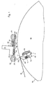
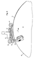
- a holder 21, for. B. an extending along the cylinder 02 Traverse 21 is provided, wherein a device for pressing an elevator 01 to the cylinder 02 of the printing press with the aid of pressing elements 31; 32, rolling elements 31 according to the invention; 32 is arranged on the holder 21, wherein the rolling elements 31; 32 to the cylinder 02 on or are offset from this.
- a first carrier 22 having a first end 23 and a second end 24 and a second carrier 26 having a first end 27 and a second end 28 are provided, wherein in one embodiment, the first end 23 of the first carrier 22 with the longitudinally the cylinder 02 extending traverse 21 is firmly connected.
- At least one first rolling element 31 is arranged at the second end 24 of the first carrier 22.
- the first end 27 of the second carrier 26 is preferably fixedly connected to the first carrier 22, preferably to the second end 24 thereof, wherein the first carrier 22 and the second carrier 26 are arranged substantially stacked with each other, the first end 27 of second carrier 26 is preferably flush with the second end 24 of the first carrier 22.
- At least one second rolling element 32 is arranged at the second end 28 of the second carrier 26.
- the first rolling element 31 and the second rolling element 32 are thus spaced one behind the other in the circumferential direction of the cylinder 02, so that-as can be seen from the figures-a so-called twin-roller or tandem roller arrangement results.
- the term tandem arrangement indicates that in the circumferential direction of the cylinder one behind the other two substantially similar components, in this case pressure elements or rolling elements are arranged.
- Such achieved independent arrival and Ab auskeit the rolling elements 31; 32 is particularly advantageous if according to the invention a plurality of elevators 01 are arranged side by side on the cylinder 02 in the axial direction and individual elevators 01 are to be selectively opened or unclamped. So z. B.
- the adjusting means 33; 34 are z. B. as a pressurizable with a pressure medium, reversibly deformable hollow body, for. B. as a hose 33; 34, executed.
- the first acting on the first carrier 22 actuating means 33 may, for. B. against a fixed connected to the cross member 21 or molded there rigid stop 29 support, because the first adjusting means 33 in particular between the crossbar 21 and the stop 29 and the first carrier 22 is arranged, whereas the second on the second carrier 26 acting Adjusting means 34 is preferably arranged between the first carrier 22 and the second carrier 26 and is preferably supported on the first end 23 of the first carrier 22 connected to the crossbeam 21.
- the carrier 22; 26 in each case as an elastically bendable, ie form reversibly deformable body, in particular in sheet-like shape, z. B. as a Spring plate 22; 26.
- a carrier 22; 26 by an operation of an associated actuating means 33; 34 can be bent elastically to a rolling element 31; 32 to make the cylinder 02, no additional means are required to the on the supports 22; 26 arranged rolling elements 31; 32 after actuation of the associated adjusting means 33; 34 again turn off the cylinder 02.
- the carrier springs 22; 26 without the help of externally attacking forces back to their original position.
- the rolling elements 31; 32 may be used as a roller 31; 32 or a roller 31; 32 be formed.
- a plurality of first carrier 22 may each be arranged next to each other with at least one first rolling element 31, these rolling elements 31 according to the invention independently or in groups by their carriers 22 associated first adjusting means 33 to the cylinder 02 on or off ,
- a preferred embodiment provides that a roller 31 extending along the cylinder 02 and a plurality of second carriers 26 having at least one roller 32 are arranged on the first carrier 22. This embodiment is particularly useful if, according to the invention, the cylinder 02 has several elevators 01 side by side and each elevator 01 is assigned a second carrier 26 with at least one second rolling element 32.
- the pressing elements 31; 32 or rolling elements 31; 32 be employed at least temporarily during the rotation of the cylinder 02.
- the device for pressing an elevator 01 to a cylinder 02 of a printing press by means of rolling elements 31; 32 has in the axial direction of the cylinder 02 both a plurality of first rolling elements 31 and a plurality of second rolling elements 32, wherein in the circumferential direction of the cylinder 02, the second rolling elements 32 are arranged spaced from the first rolling elements 31. It is then characterized by the fact that individual or groups of second rolling elements 32 can be adjusted independently of individual or groups of first rolling elements 31 to the cylinder 02 or offset from this. But it can also all first rolling elements 31 employed and the second rolling elements 32 partially on or off.
- the suspension leg 03a at the leading end of the elevator 01 is preferably tangential brought to the lateral surface 06 of the cylinder 02 and mounted on the first wall 04 of the introduced into the lateral surface 06 of the cylinder 02 opening 07.
- the cylinder 02 is rotated so far in its production direction P until the suspension leg 03b at the trailing end of the elevator 01 on the second wall 17 of the same or an identically shaped, on the circumference of the cylinder 02 offset to the first opening 07 arranged second opening 07 is present, the Rolling elements 32 press the elevator 01 to the lateral surface 06 of the cylinder 02.
- the rolling element 32 closest to the trailing end of the elevator 01 presses the suspension leg 03b into the opening 07 and the retaining means 12 holding the elevator 01 changes from its release position into its holding position.
- the rolling elements 31; 32 are placed on one or more resting on the outer surface 06 of the cylinder 02 elevators 01.
- the cylinder 02 rotates until the arranged on the second carrier 26 rolling element 32 is present at the suspension leg 03b of the trailing end of an elevator to be peeled 01.
- the Wälzelement 32 pending on the suspension leg 03b of the trailing end of the elevator 01 to be tensioned is turned off by the cylinder 02 and the holding means 12 of the holding device preferably changes to its release position by pivoting, whereupon the suspension leg 03b automatically engages at the trailing end of the elevator 01 to be tensioned by its residual stress Opening 07 springs out, while the suspension legs 03b remain at the trailing end of further resting on the cylinder 02 elevators 01 due to the pressing rolling elements 32 on the second wall 17 of the opening 07 remain applied.
- the holding means 12 of the holding device preferably again switches to its holding position and the cylinder 02 rotates counter to its production direction P until the suspension leg 03a at the leading end of the elevator 01 to be clamped from the first wall 04 of the opening 07 aushssenbar and thus removable from the cylinder 02 ,
- the rolling elements 31; 32 are parked by all 01 on the outer surface 06 of the cylinder 02 lifts.
- the cylinder 02 rotates until the arranged on the second carrier 26 rolling element 32 is above the suspension leg 03b at the trailing end of the elevators 01, d. H. Although still out of contact, but still in their immediate vicinity.
- the holding means 12 of the holding device preferably changes by pivoting into its release position, whereupon the suspension leg 03b automatically springs out of the opening 07 at the trailing end of all elevators 01 by residual stress.
- the elevators 01 remain fixed on the outer surface 06 of the cylinder 02 due to the rolling elements 31 engaged with the cylinder 02.
- the holding means 12 of the holding device changes back to its holding position and all rolling elements 31; 32 are turned off by the cylinder 02.
- the cylinder 02 rotates counter to its direction of production P until the suspension leg 03a at the leading end of the elevator 01 to be tensioned from the first wall 04 of the opening 07 aushssenbar and thus removable from the cylinder 02.
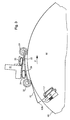
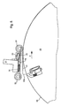
- FIG. 7 shows an assignment of rolling elements 32 arranged on a plurality of second carriers 26 to a plurality of elevators 01 applied next to each other on a cylinder 02 during unclamping of one of these elevators 01.
- three rolling elements 32 are assigned to one elevator 01.
- These rolling elements 32 can be independent of the other rolling elements 31; 32 from the cylinder 02 on or off, while z. B. adjacent elevators 01 are pressed against the outer surface 06 of the cylinder 02.
- the rolling element 31 here is a continuous roller 31, whereas the rolling elements 32 consists of a plurality of individual rollers 32.
- the rolling elements 31; 32 are arranged spaced apart in the circumferential direction of the cylinder 02.
- the roller 31 is in contact with all the elevators 01 resting side by side on the cylinder 02, while the trailing end of the elevator 01 to be tensioned is released.
- the rolling elements 31; 32 preferably with pneumatically actuable adjusting means 33; 34 on the cylinder 02 on or off.
- the rolling elements 31; 32 are placed on all of the outer surface 06 of the cylinder 02 resting lifts 01.
- the cylinder 02 rotates until the arranged on the second carrier 26 rolling element 32 is above the opening 07 at the trailing end of an elevator 01 to be tensioned.
- the holding means 12 of the holding device changes to its release position.
- the suspension legs 03b of the other elevators 01 remain in the opening 07, because the ends of these elevators 01 remain pressed against the lateral surface 06 of the cylinder 02 by the first rolling element 31 assigned to them.
- the length of the dissolved end of an elevator 01 to be removed from the cylinder 02 is determined by the distance of the contact point of the first rolling element 31 on the cylinder 02 from the opening 07.
- the holding means 12 of the holding device changes into its holding position and all rolling elements 31; 32 or at least the first front in the direction of production P rolling elements 31 can be turned off by the cylinder 02. Thereafter, if necessary, after a rotation of the cylinder 02 against its production direction P, the elevator 01 to be tensioned can be removed from the lateral surface 06 of the cylinder 02.
- the pre-arranged in the production direction P of the cylinder 02, to be pressed to the elevator 01 pressing member 31 is preferably employed at a time to the cylinder 02, to which the trailing arranged pressing member 32 due to a rotational movement of the cylinder 02 on one in the Cylinder 02 introduced opening 07 or near this opening 07, wherein a suspension leg 03b is held in the production direction P of the cylinder 02 trailing end of the elevator 01 in this opening 07.
- the Ceimonyden elevator 01 employed pressure element 32 is preferably then turned off by the cylinder 02, as soon as this Andschreibelement 32 due to a rotational movement of the cylinder 02 on an introduced into the cylinder 02 opening 07 or near this opening 07 and a suspension leg 03b on the trailing in the direction of production P of the cylinder 02 end of the elevator 01 in this opening 07 holding means 12 is changed from its holding position to its release position. After this change of the hanging leg 03b holding in this opening 07 holding means 12, this suspension leg 03b can preferably solve automatically from the opening 07.
- the further in the direction of production P of the cylinder 02 precedently arranged pressing member 31 preferably remains as long as employed on the elevator 01 to be pressed until this Andschreibelement 31 due to a directed against its direction of production P rotational movement of the cylinder 02 on a in the Cylinder 02 introduced opening 07 or near this opening 07 is located, wherein a suspension leg 03a is held in the production direction P of the cylinder 02 leading end of the elevator 01 in this opening 07. Accordingly, the elevator 01 remains fixed on the cylinder 02 by the employed pressing element 31 arranged in advance in the production direction P of the cylinder 02 until the suspension leg 03a can be removed from the opening 07 on the end of the elevator 01 leading in the production direction P of the cylinder 02.
- a method for pressing an elevator 01 to a cylinder 02 of a printing press in which a plurality of elevators 01 are arranged side by side on the cylinder 02 in the axial direction, can provide that at least one rolling element 32 pressing on the cylinder 02 at the beginning is provided of the Aufspannvorgangs employed on the cylinder 02 and is turned off again by the cylinder 02 at the end of the Aufspannvorgangs.
- a holding means 12 holding the suspension leg 03b at the trailing end in the direction of production P of the cylinder 02 then changes from a release position to a holding position.
- the rolling element 32 is preferably turned off after the change of the holding means 12 from its release position to its holding position by the cylinder 02.
- the cylinder 02 is rotated in its production direction P after hanging the Einpatinlegeels 03a at the leading end in the direction of production P of the cylinder 02 until the suspension leg 03b can be suspended on the trailing in the direction of production P of the cylinder 02 end.
- the rolling element 32 associated with the elevator 01 to be tensioned becomes independently of a different roller 01 assigned to a rolling element 32 to the cylinder 02 employed or parked by the cylinder 02.
- a plurality of rolling elements 32 associated with the elevators 01 are preferably arranged side by side. It can be provided that at the beginning of the clamping operation only the rolling element 32 associated with the elevator 01 to be tensioned is turned on.
Landscapes
- Rolls And Other Rotary Bodies (AREA)
- Rotary Presses (AREA)
- Inking, Control Or Cleaning Of Printing Machines (AREA)
- Supply, Installation And Extraction Of Printed Sheets Or Plates (AREA)
- Folding Of Thin Sheet-Like Materials, Special Discharging Devices, And Others (AREA)
Claims (7)
- Procédé de pressage d'un habillage (01) sur un cylindre (02) d'une machine à imprimer, où un élément roulement (32), pressant l'habillage (01) devant être appliqué de façon tendue sur le cylindre (02), au début du processus d'application tendue est plaqué sur le cylindre (02) et ensuite, à la fin du processus d'application tendue, est de nouveau dégagé du cylindre (02), où plusieurs habillages (01) sont susceptibles d'être disposés sur le cylindre (02), l'élément à roulement (32), associé à l'habillage (01) devant être appliqué de façon tendue, étant plaqué sur le cylindre (02) ou dégagé du cylindre (02), indépendamment d'un élément à roulement (32) associé à un autre habillage (01), caractérisé en ce que, sur le cylindre (02), dans sa direction axiale, peuvent être disposés les uns à côté des autres plusieurs habillages (01), sachant qu'en direction axiale du cylindre (02) sont utilisés plusieurs éléments à roulement (32), associés aux habillages (01), disposés les uns à côté des autres, et où, au début du processus d'application tendue, n'est appliqué que l'élément à roulement (32) associé à l'habillage (01) pouvant être appliqué de façon tendue.
- Procédé selon la revendication 1, caractérisé en ce que sont utilisés des habillages (01), ayant des branches d'accrochage (03a; 03b) à leurs extrémités, pour accrochage dans une ouverture (37) ménagée dans le cylindre (02).
- Procédé selon la revendication 2, caractérisé en ce que, au début du processus d'application tendue, est accrochée dans l'ouverture (07) la branche d'accrochage (03a), se trouvant à l'extrémité de l'habillage (01) située à l'avant en observant dans le sens de production (P) du cylindre (02),.
- Procédé selon la revendication 2, caractérisé en ce que, à la fin du processus d'application tendue, est accrochée dans l'ouverture (07) la branche d'accrochage (03b), se trouvant à l'extrémité arrière, en observant dans le sens de production (P) du cylindre (02).
- Procédé selon la revendication 4, caractérisé en ce qu'un moyen de maintien (12), maintenant la branche d'accrochage (03b), se trouvant à l'extrémité arrière, en observant dans le sens de production (P) du cylindre (02), passe d'une position de libération à une position de maintien.
- Procédé selon la revendication 5, caractérisé en ce que l'élément à roulement (32) est dégagé du cylindre (02), après passage du moyen de maintien (12) de sa position de libération à sa position de maintien.
- Procédé selon la revendication 2, caractérisé en ce que, après accrochage de la branche d'accrochage (03a) sur l'extrémité, située à l'avant en l'observant dans le sens de production (P) du cylindre (02), le cylindre (02) est tourné dans son sens de production (P), jusqu'à ce que la branche d'accrochage (03b) puisse être accrochée sur l'extrémité arrière, en observant dans le sens de production (P) du cylindre (02).
Applications Claiming Priority (3)
| Application Number | Priority Date | Filing Date | Title |
|---|---|---|---|
| DE10238177 | 2002-08-21 | ||
| DE10238177A DE10238177B3 (de) | 2002-08-21 | 2002-08-21 | Vorrichtung zum Andrücken eines Aufzugs an einen Zylinder einer Druckmaschine mit Hilfe von in Umfangsrichtung des Zylinders voneinander beabstandeten ersten und zweiten Wälzelementen |
| EP03790689A EP1530513B1 (fr) | 2002-08-21 | 2003-08-07 | Dispositif et procede pour faire appuyer un habillage contre le cylindre d'une machine d'impression au moyen d'elements d'appui |
Related Parent Applications (1)
| Application Number | Title | Priority Date | Filing Date |
|---|---|---|---|
| EP03790689A Division EP1530513B1 (fr) | 2002-08-21 | 2003-08-07 | Dispositif et procede pour faire appuyer un habillage contre le cylindre d'une machine d'impression au moyen d'elements d'appui |
Publications (3)
| Publication Number | Publication Date |
|---|---|
| EP1535735A2 EP1535735A2 (fr) | 2005-06-01 |
| EP1535735A3 EP1535735A3 (fr) | 2006-05-31 |
| EP1535735B1 true EP1535735B1 (fr) | 2006-09-20 |
Family
ID=30010620
Family Applications (6)
| Application Number | Title | Priority Date | Filing Date |
|---|---|---|---|
| EP03790688A Expired - Lifetime EP1530516B1 (fr) | 2002-08-21 | 2003-08-07 | Dispositifs pour faire appuyer un habillage contre un cylindre d'une machine d'impression |
| EP05100974A Withdrawn EP1543968A3 (fr) | 2002-08-21 | 2003-08-07 | Dispositif pour appliquer un recouvrement sur un cylindre d'une machine à imprimer |
| EP05100932A Expired - Lifetime EP1535734B1 (fr) | 2002-08-21 | 2003-08-07 | Procédé pour presser un recouvrement sur un cylindre d'une machine à imprimer avec des éléments de pression |
| EP03790689A Expired - Lifetime EP1530513B1 (fr) | 2002-08-21 | 2003-08-07 | Dispositif et procede pour faire appuyer un habillage contre le cylindre d'une machine d'impression au moyen d'elements d'appui |
| EP05100973A Withdrawn EP1543967A3 (fr) | 2002-08-21 | 2003-08-07 | Procédé pour tendre un habillage sur un cylindre et procédé pour détendre l'habillage d'un cylindre d'une machine à imprimer |
| EP05100934A Expired - Lifetime EP1535735B1 (fr) | 2002-08-21 | 2003-08-07 | Procédé pour presser un recouvrement sur un cylindre d'une machine d'impression |
Family Applications Before (5)
| Application Number | Title | Priority Date | Filing Date |
|---|---|---|---|
| EP03790688A Expired - Lifetime EP1530516B1 (fr) | 2002-08-21 | 2003-08-07 | Dispositifs pour faire appuyer un habillage contre un cylindre d'une machine d'impression |
| EP05100974A Withdrawn EP1543968A3 (fr) | 2002-08-21 | 2003-08-07 | Dispositif pour appliquer un recouvrement sur un cylindre d'une machine à imprimer |
| EP05100932A Expired - Lifetime EP1535734B1 (fr) | 2002-08-21 | 2003-08-07 | Procédé pour presser un recouvrement sur un cylindre d'une machine à imprimer avec des éléments de pression |
| EP03790689A Expired - Lifetime EP1530513B1 (fr) | 2002-08-21 | 2003-08-07 | Dispositif et procede pour faire appuyer un habillage contre le cylindre d'une machine d'impression au moyen d'elements d'appui |
| EP05100973A Withdrawn EP1543967A3 (fr) | 2002-08-21 | 2003-08-07 | Procédé pour tendre un habillage sur un cylindre et procédé pour détendre l'habillage d'un cylindre d'une machine à imprimer |
Country Status (8)
| Country | Link |
|---|---|
| US (2) | US7237484B2 (fr) |
| EP (6) | EP1530516B1 (fr) |
| CN (1) | CN1328047C (fr) |
| AT (4) | ATE340078T1 (fr) |
| AU (2) | AU2003266108A1 (fr) |
| DE (5) | DE10238177B3 (fr) |
| ES (2) | ES2270404T3 (fr) |
| WO (2) | WO2004020198A2 (fr) |
Families Citing this family (7)
| Publication number | Priority date | Publication date | Assignee | Title |
|---|---|---|---|---|
| DE102004059338B3 (de) * | 2004-08-16 | 2005-12-22 | Koenig & Bauer Ag | Verfahren und Vorrichtung zum Abspannen mindestens eines Aufzugs von einem Zylinder einer Druckmaschine |
| DE102005017182A1 (de) | 2005-04-13 | 2006-10-19 | Man Roland Druckmaschinen Ag | Vorrichtung und Verfahren zum Andrücken einer Bespannung an einen Druckwerkzylinder einer Rotationsdruckmaschine |
| DE102006059772A1 (de) * | 2006-12-15 | 2008-06-19 | Man Roland Druckmaschinen Ag | Vorrichtung zur Durchführung eines Druckplattenwechsels an einem Formzylinder einer Druckmaschine |
| DE102007000639B3 (de) * | 2007-03-02 | 2008-08-07 | Koenig & Bauer Aktiengesellschaft | Vorrichtung mit mehreren selektiv betätigbaren Funktionseinheiten |
| DE102007000728B4 (de) * | 2007-09-13 | 2010-06-02 | Koenig & Bauer Aktiengesellschaft | Rotationsdruckmaschinen mit mindestens einer Störschall emittierenden Druckeinheit |
| PL2844471T3 (pl) * | 2012-04-24 | 2019-03-29 | Tresu A/S | Jednostka nakładania farby z regulacją wałków przez płytkę zginającą oraz sposób regulacji |
| DE102015210819A1 (de) | 2015-06-12 | 2016-12-15 | Koenig & Bauer Ag | Vorrichtung zum Auflegen zumindest eines Aufzugs auf eine Mantelfläche eines Zylinders einer Druckmaschine und ein Verfahren zum Auflegen zumindest eines Aufzugs auf eine Mantelfläche eines Zylinders einer Druckmaschine |
Citations (1)
| Publication number | Priority date | Publication date | Assignee | Title |
|---|---|---|---|---|
| US6199280B1 (en) * | 1997-05-09 | 2001-03-13 | Koening & Bauer Aktiengesellschaft | Method and device for assembling flexible plates, for example printing plates |
Family Cites Families (14)
| Publication number | Priority date | Publication date | Assignee | Title |
|---|---|---|---|---|
| US540600A (en) * | 1895-06-04 | Sash-pulley | ||
| US4727807A (en) * | 1985-09-30 | 1988-03-01 | Tokyo Kikai Seisakusho | Apparatus for automatically mounting and removing printing plates in rotary printing press |
| DE69018036T3 (de) * | 1989-12-06 | 2001-02-15 | Komori Printing Mach | Apparat zum Wechseln von Druckplatten für Druckpresse. |
| DE4414443C1 (de) * | 1994-04-26 | 1995-11-30 | Heidelberger Druckmasch Ag | Vorrichtung zum Führen eines Druckträgers |
| DE4440239C5 (de) * | 1994-11-10 | 2007-11-22 | Man Roland Druckmaschinen Ag | Wälzelement zum Andrücken einer flexiblen Druckplatte an den Formzylinder |
| DE19620997C2 (de) * | 1996-05-24 | 1998-03-26 | Koenig & Bauer Albert Ag | Verfahren und Vorrichtung zum axialen Positionieren einer Druckplatte |
| DE19639800C1 (de) * | 1996-09-27 | 1998-02-05 | Kba Planeta Ag | Vorrichtung zum Positionieren des freien Endes einer Druckplatte |
| US6792860B2 (en) * | 2000-05-17 | 2004-09-21 | Koenig & Bauer Aktiengesellschaft | Method and device for pressing a packing against a cylinder |
| JP4187969B2 (ja) * | 2000-05-17 | 2008-11-26 | ケーニツヒ ウント バウエル アクチエンゲゼルシヤフト | 胴に胴張りを圧着するための装置 |
| US6439117B1 (en) | 2000-05-17 | 2002-08-27 | Heidelberger Druckmaschinen Ag | Printing press with multi-plate plate cylinder |
| DE10058996C1 (de) * | 2000-11-28 | 2002-06-13 | Koenig & Bauer Ag | Vorrichtung zur Befestigung eines Aufzuges |
| EP1432578B1 (fr) * | 2001-10-05 | 2005-12-14 | Koenig & Bauer Aktiengesellschaft | Presse rotative a imprimer |
| DE10158158A1 (de) | 2001-11-28 | 2003-06-18 | Koenig & Bauer Ag | Vorrichtung zum Aufziehen eines Aufzuges |
| EP1453678B1 (fr) * | 2001-11-28 | 2005-04-20 | Koenig & Bauer Aktiengesellschaft | Dispositifs et procedes permettant l'alignement ou le montage d'un habillage applique sur un cylindre d'une imprimante |
-
2002
- 2002-08-21 DE DE10238177A patent/DE10238177B3/de not_active Expired - Fee Related
-
2003
- 2003-08-07 DE DE50312245T patent/DE50312245D1/de not_active Expired - Lifetime
- 2003-08-07 EP EP03790688A patent/EP1530516B1/fr not_active Expired - Lifetime
- 2003-08-07 EP EP05100974A patent/EP1543968A3/fr not_active Withdrawn
- 2003-08-07 WO PCT/DE2003/002651 patent/WO2004020198A2/fr active IP Right Grant
- 2003-08-07 AT AT05100934T patent/ATE340078T1/de not_active IP Right Cessation
- 2003-08-07 AT AT05100932T patent/ATE452026T1/de not_active IP Right Cessation
- 2003-08-07 US US10/524,878 patent/US7237484B2/en not_active Expired - Fee Related
- 2003-08-07 AU AU2003266108A patent/AU2003266108A1/en not_active Abandoned
- 2003-08-07 ES ES05100934T patent/ES2270404T3/es not_active Expired - Lifetime
- 2003-08-07 AU AU2003266109A patent/AU2003266109A1/en not_active Abandoned
- 2003-08-07 AT AT03790689T patent/ATE350218T1/de not_active IP Right Cessation
- 2003-08-07 AT AT03790688T patent/ATE448083T1/de not_active IP Right Cessation
- 2003-08-07 EP EP05100932A patent/EP1535734B1/fr not_active Expired - Lifetime
- 2003-08-07 CN CNB038195771A patent/CN1328047C/zh not_active Expired - Fee Related
- 2003-08-07 US US10/525,018 patent/US7240616B2/en not_active Expired - Fee Related
- 2003-08-07 EP EP03790689A patent/EP1530513B1/fr not_active Expired - Lifetime
- 2003-08-07 DE DE50312116T patent/DE50312116D1/de not_active Expired - Lifetime
- 2003-08-07 EP EP05100973A patent/EP1543967A3/fr not_active Withdrawn
- 2003-08-07 EP EP05100934A patent/EP1535735B1/fr not_active Expired - Lifetime
- 2003-08-07 ES ES03790689T patent/ES2277140T3/es not_active Expired - Lifetime
- 2003-08-07 DE DE50306205T patent/DE50306205D1/de not_active Expired - Lifetime
- 2003-08-07 WO PCT/DE2003/002650 patent/WO2004020205A2/fr not_active Application Discontinuation
- 2003-08-07 DE DE50305132T patent/DE50305132D1/de not_active Expired - Lifetime
Patent Citations (1)
| Publication number | Priority date | Publication date | Assignee | Title |
|---|---|---|---|---|
| US6199280B1 (en) * | 1997-05-09 | 2001-03-13 | Koening & Bauer Aktiengesellschaft | Method and device for assembling flexible plates, for example printing plates |
Also Published As
Similar Documents
| Publication | Publication Date | Title |
|---|---|---|
| EP2028007B1 (fr) | Unité d'impression comprenant plusieurs groupe d'impression | |
| EP0678382A1 (fr) | Dispositif pour remplacer la plaque d'impression pour des machines d'impression rotatives | |
| EP1759843A2 (fr) | Cylindre d'impression avec un dispositif assigné à ce cylindre pour charger ou décharger au minimum une plaque sur le et/ou du cylindre | |
| EP1535735B1 (fr) | Procédé pour presser un recouvrement sur un cylindre d'une machine d'impression | |
| EP1530515B1 (fr) | Procede de remplacement d'au moins un bloc d'impression d'une machine a imprimer comportant plusieurs cylindres graves | |
| EP1530514B1 (fr) | Procede permettant de monter un habillage sur le cylindre d'une machine a imprimer | |
| EP1453678B1 (fr) | Dispositifs et procedes permettant l'alignement ou le montage d'un habillage applique sur un cylindre d'une imprimante | |
| DE102006050568B3 (de) | Vorrichtung zum Andrücken eines Aufzugs an einen Zylinder | |
| EP1531995B1 (fr) | Dispositif pour guider un habillage sur le cylindre d'une machine d'impression | |
| EP3546215B1 (fr) | Dispositif pour fixer des plaques d'impression sur un cylindre porte-plaque | |
| EP1632350B1 (fr) | Procédé et dispositif pour détendre un habillage d'un cylindre d'une machine d'impression. | |
| EP3615338B1 (fr) | Unité d'impression prévue pour imprimer des supports d'impression en feuille, machine pour impression sur métaux avec une telle unité d'impression et procédé de montage d'ascenseurs dans les cylindres d'une unité d'impression pour imprimante sur feuilles | |
| EP2644382B1 (fr) | Ensemble comprenant un cylindre de plaque d'une machine à imprimer, une plaque d'impression flexible et un élément de repérage | |
| EP2644381B1 (fr) | Procédé de liaison par complémentarité de forme d'un bloc d'impression souple avec un élément de repérage et/ou de séparation d'une telle liaison | |
| EP1531994B1 (fr) | Procede et dispositif permettant de retirer l'habillage d'un cylindre d'une machine a imprimer | |
| DE4239253A1 (de) | Einrichtung zum automatischen Auszug von flexiblen Druckplatten | |
| EP1070584A1 (fr) | Machine à imprimer des feuilles | |
| EP1900525A2 (fr) | Dispositif destiné au montage d'une plaque d'impression sur un cylindre porte-plaque d'une machine d'impression |
Legal Events
| Date | Code | Title | Description |
|---|---|---|---|
| PUAI | Public reference made under article 153(3) epc to a published international application that has entered the european phase |
Free format text: ORIGINAL CODE: 0009012 |
|
| AC | Divisional application: reference to earlier application |
Ref document number: 1530513 Country of ref document: EP Kind code of ref document: P |
|
| AK | Designated contracting states |
Kind code of ref document: A2 Designated state(s): AT BE BG CH CY CZ DE DK EE ES FI FR GB GR HU IE IT LI LU MC NL PT RO SE SI SK TR |
|
| AX | Request for extension of the european patent |
Extension state: AL LT LV MK |
|
| PUAL | Search report despatched |
Free format text: ORIGINAL CODE: 0009013 |
|
| AK | Designated contracting states |
Kind code of ref document: A3 Designated state(s): AT BE BG CH CY CZ DE DK EE ES FI FR GB GR HU IE IT LI LU MC NL PT RO SE SI SK TR |
|
| AX | Request for extension of the european patent |
Extension state: AL LT LV MK |
|
| 17P | Request for examination filed |
Effective date: 20060419 |
|
| GRAP | Despatch of communication of intention to grant a patent |
Free format text: ORIGINAL CODE: EPIDOSNIGR1 |
|
| GRAS | Grant fee paid |
Free format text: ORIGINAL CODE: EPIDOSNIGR3 |
|
| GRAA | (expected) grant |
Free format text: ORIGINAL CODE: 0009210 |
|
| AC | Divisional application: reference to earlier application |
Ref document number: 1530513 Country of ref document: EP Kind code of ref document: P |
|
| AK | Designated contracting states |
Kind code of ref document: B1 Designated state(s): AT BE BG CH CY CZ DE DK EE ES FI FR GB GR HU IE IT LI LU MC NL PT RO SE SI SK TR |
|
| PG25 | Lapsed in a contracting state [announced via postgrant information from national office to epo] |
Ref country code: IT Free format text: LAPSE BECAUSE OF FAILURE TO SUBMIT A TRANSLATION OF THE DESCRIPTION OR TO PAY THE FEE WITHIN THE PRESCRIBED TIME-LIMIT;WARNING: LAPSES OF ITALIAN PATENTS WITH EFFECTIVE DATE BEFORE 2007 MAY HAVE OCCURRED AT ANY TIME BEFORE 2007. THE CORRECT EFFECTIVE DATE MAY BE DIFFERENT FROM THE ONE RECORDED. Effective date: 20060920 Ref country code: SI Free format text: LAPSE BECAUSE OF FAILURE TO SUBMIT A TRANSLATION OF THE DESCRIPTION OR TO PAY THE FEE WITHIN THE PRESCRIBED TIME-LIMIT Effective date: 20060920 Ref country code: NL Free format text: LAPSE BECAUSE OF FAILURE TO SUBMIT A TRANSLATION OF THE DESCRIPTION OR TO PAY THE FEE WITHIN THE PRESCRIBED TIME-LIMIT Effective date: 20060920 Ref country code: CZ Free format text: LAPSE BECAUSE OF FAILURE TO SUBMIT A TRANSLATION OF THE DESCRIPTION OR TO PAY THE FEE WITHIN THE PRESCRIBED TIME-LIMIT Effective date: 20060920 Ref country code: IE Free format text: LAPSE BECAUSE OF FAILURE TO SUBMIT A TRANSLATION OF THE DESCRIPTION OR TO PAY THE FEE WITHIN THE PRESCRIBED TIME-LIMIT Effective date: 20060920 Ref country code: RO Free format text: LAPSE BECAUSE OF FAILURE TO SUBMIT A TRANSLATION OF THE DESCRIPTION OR TO PAY THE FEE WITHIN THE PRESCRIBED TIME-LIMIT Effective date: 20060920 Ref country code: SK Free format text: LAPSE BECAUSE OF FAILURE TO SUBMIT A TRANSLATION OF THE DESCRIPTION OR TO PAY THE FEE WITHIN THE PRESCRIBED TIME-LIMIT Effective date: 20060920 |
|
| REG | Reference to a national code |
Ref country code: GB Ref legal event code: FG4D Free format text: NOT ENGLISH |
|
| REG | Reference to a national code |
Ref country code: CH Ref legal event code: EP |
|
| GBT | Gb: translation of ep patent filed (gb section 77(6)(a)/1977) |
Effective date: 20061005 |
|
| REG | Reference to a national code |
Ref country code: IE Ref legal event code: FG4D Free format text: LANGUAGE OF EP DOCUMENT: GERMAN |
|
| REF | Corresponds to: |
Ref document number: 50305132 Country of ref document: DE Date of ref document: 20061102 Kind code of ref document: P |
|
| PG25 | Lapsed in a contracting state [announced via postgrant information from national office to epo] |
Ref country code: BG Free format text: LAPSE BECAUSE OF FAILURE TO SUBMIT A TRANSLATION OF THE DESCRIPTION OR TO PAY THE FEE WITHIN THE PRESCRIBED TIME-LIMIT Effective date: 20061220 Ref country code: SE Free format text: LAPSE BECAUSE OF FAILURE TO SUBMIT A TRANSLATION OF THE DESCRIPTION OR TO PAY THE FEE WITHIN THE PRESCRIBED TIME-LIMIT Effective date: 20061220 Ref country code: DK Free format text: LAPSE BECAUSE OF FAILURE TO SUBMIT A TRANSLATION OF THE DESCRIPTION OR TO PAY THE FEE WITHIN THE PRESCRIBED TIME-LIMIT Effective date: 20061220 |
|
| AKX | Designation fees paid |
Designated state(s): AT BE BG CH CY CZ DE DK EE ES FI FR GB GR HU IE IT LI LU MC NL PT RO SE SI SK TR |
|
| NLV1 | Nl: lapsed or annulled due to failure to fulfill the requirements of art. 29p and 29m of the patents act | ||
| PG25 | Lapsed in a contracting state [announced via postgrant information from national office to epo] |
Ref country code: PT Free format text: LAPSE BECAUSE OF FAILURE TO SUBMIT A TRANSLATION OF THE DESCRIPTION OR TO PAY THE FEE WITHIN THE PRESCRIBED TIME-LIMIT Effective date: 20070312 |
|
| ET | Fr: translation filed | ||
| REG | Reference to a national code |
Ref country code: ES Ref legal event code: FG2A Ref document number: 2270404 Country of ref document: ES Kind code of ref document: T3 |
|
| REG | Reference to a national code |
Ref country code: IE Ref legal event code: FD4D |
|
| PLBE | No opposition filed within time limit |
Free format text: ORIGINAL CODE: 0009261 |
|
| STAA | Information on the status of an ep patent application or granted ep patent |
Free format text: STATUS: NO OPPOSITION FILED WITHIN TIME LIMIT |
|
| 26N | No opposition filed |
Effective date: 20070621 |
|
| BERE | Be: lapsed |
Owner name: KOENIG & BAUER A.G. Effective date: 20070831 |
|
| PG25 | Lapsed in a contracting state [announced via postgrant information from national office to epo] |
Ref country code: GR Free format text: LAPSE BECAUSE OF FAILURE TO SUBMIT A TRANSLATION OF THE DESCRIPTION OR TO PAY THE FEE WITHIN THE PRESCRIBED TIME-LIMIT Effective date: 20061221 Ref country code: MC Free format text: LAPSE BECAUSE OF NON-PAYMENT OF DUE FEES Effective date: 20070831 |
|
| PG25 | Lapsed in a contracting state [announced via postgrant information from national office to epo] |
Ref country code: EE Free format text: LAPSE BECAUSE OF FAILURE TO SUBMIT A TRANSLATION OF THE DESCRIPTION OR TO PAY THE FEE WITHIN THE PRESCRIBED TIME-LIMIT Effective date: 20060920 |
|
| PG25 | Lapsed in a contracting state [announced via postgrant information from national office to epo] |
Ref country code: BE Free format text: LAPSE BECAUSE OF NON-PAYMENT OF DUE FEES Effective date: 20070831 |
|
| PGFP | Annual fee paid to national office [announced via postgrant information from national office to epo] |
Ref country code: ES Payment date: 20080820 Year of fee payment: 6 |
|
| PG25 | Lapsed in a contracting state [announced via postgrant information from national office to epo] |
Ref country code: AT Free format text: LAPSE BECAUSE OF NON-PAYMENT OF DUE FEES Effective date: 20070807 |
|
| PGFP | Annual fee paid to national office [announced via postgrant information from national office to epo] |
Ref country code: IT Payment date: 20080826 Year of fee payment: 6 |
|
| PG25 | Lapsed in a contracting state [announced via postgrant information from national office to epo] |
Ref country code: FI Free format text: LAPSE BECAUSE OF FAILURE TO SUBMIT A TRANSLATION OF THE DESCRIPTION OR TO PAY THE FEE WITHIN THE PRESCRIBED TIME-LIMIT Effective date: 20060920 Ref country code: CY Free format text: LAPSE BECAUSE OF FAILURE TO SUBMIT A TRANSLATION OF THE DESCRIPTION OR TO PAY THE FEE WITHIN THE PRESCRIBED TIME-LIMIT Effective date: 20060920 Ref country code: LU Free format text: LAPSE BECAUSE OF NON-PAYMENT OF DUE FEES Effective date: 20070807 |
|
| PG25 | Lapsed in a contracting state [announced via postgrant information from national office to epo] |
Ref country code: HU Free format text: LAPSE BECAUSE OF FAILURE TO SUBMIT A TRANSLATION OF THE DESCRIPTION OR TO PAY THE FEE WITHIN THE PRESCRIBED TIME-LIMIT Effective date: 20070321 Ref country code: TR Free format text: LAPSE BECAUSE OF FAILURE TO SUBMIT A TRANSLATION OF THE DESCRIPTION OR TO PAY THE FEE WITHIN THE PRESCRIBED TIME-LIMIT Effective date: 20060920 |
|
| REG | Reference to a national code |
Ref country code: ES Ref legal event code: FD2A Effective date: 20090808 |
|
| PG25 | Lapsed in a contracting state [announced via postgrant information from national office to epo] |
Ref country code: IT Free format text: LAPSE BECAUSE OF NON-PAYMENT OF DUE FEES Effective date: 20090807 |
|
| PG25 | Lapsed in a contracting state [announced via postgrant information from national office to epo] |
Ref country code: ES Free format text: LAPSE BECAUSE OF NON-PAYMENT OF DUE FEES Effective date: 20090808 |
|
| PGFP | Annual fee paid to national office [announced via postgrant information from national office to epo] |
Ref country code: CH Payment date: 20110822 Year of fee payment: 9 |
|
| REG | Reference to a national code |
Ref country code: CH Ref legal event code: PL |
|
| PG25 | Lapsed in a contracting state [announced via postgrant information from national office to epo] |
Ref country code: CH Free format text: LAPSE BECAUSE OF NON-PAYMENT OF DUE FEES Effective date: 20130831 Ref country code: LI Free format text: LAPSE BECAUSE OF NON-PAYMENT OF DUE FEES Effective date: 20130831 |
|
| REG | Reference to a national code |
Ref country code: FR Ref legal event code: PLFP Year of fee payment: 13 |
|
| REG | Reference to a national code |
Ref country code: DE Ref legal event code: R081 Ref document number: 50305132 Country of ref document: DE Owner name: KOENIG & BAUER AG, DE Free format text: FORMER OWNER: KOENIG & BAUER AKTIENGESELLSCHAFT, 97080 WUERZBURG, DE |
|
| PGFP | Annual fee paid to national office [announced via postgrant information from national office to epo] |
Ref country code: GB Payment date: 20150824 Year of fee payment: 13 Ref country code: DE Payment date: 20150918 Year of fee payment: 13 |
|
| PGFP | Annual fee paid to national office [announced via postgrant information from national office to epo] |
Ref country code: FR Payment date: 20150824 Year of fee payment: 13 |
|
| REG | Reference to a national code |
Ref country code: DE Ref legal event code: R119 Ref document number: 50305132 Country of ref document: DE |
|
| GBPC | Gb: european patent ceased through non-payment of renewal fee |
Effective date: 20160807 |
|
| REG | Reference to a national code |
Ref country code: FR Ref legal event code: ST Effective date: 20170428 |
|
| PG25 | Lapsed in a contracting state [announced via postgrant information from national office to epo] |
Ref country code: FR Free format text: LAPSE BECAUSE OF NON-PAYMENT OF DUE FEES Effective date: 20160831 Ref country code: DE Free format text: LAPSE BECAUSE OF NON-PAYMENT OF DUE FEES Effective date: 20170301 Ref country code: GB Free format text: LAPSE BECAUSE OF NON-PAYMENT OF DUE FEES Effective date: 20160807 |