EP1535542B1 - Schaukasten - Google Patents
Schaukasten Download PDFInfo
- Publication number
- EP1535542B1 EP1535542B1 EP20040257359 EP04257359A EP1535542B1 EP 1535542 B1 EP1535542 B1 EP 1535542B1 EP 20040257359 EP20040257359 EP 20040257359 EP 04257359 A EP04257359 A EP 04257359A EP 1535542 B1 EP1535542 B1 EP 1535542B1
- Authority
- EP
- European Patent Office
- Prior art keywords
- door
- arm
- metal fittings
- main body
- housing
- Prior art date
- Legal status (The legal status is an assumption and is not a legal conclusion. Google has not performed a legal analysis and makes no representation as to the accuracy of the status listed.)
- Expired - Lifetime
Links
- 239000000696 magnetic material Substances 0.000 claims description 4
- 239000002184 metal Substances 0.000 description 45
- 238000001816 cooling Methods 0.000 description 9
- 229920003002 synthetic resin Polymers 0.000 description 5
- 239000000057 synthetic resin Substances 0.000 description 5
- 238000005452 bending Methods 0.000 description 4
- 238000001125 extrusion Methods 0.000 description 2
- 239000011521 glass Substances 0.000 description 2
- 238000003780 insertion Methods 0.000 description 2
- 230000037431 insertion Effects 0.000 description 2
- 239000011810 insulating material Substances 0.000 description 2
- 239000003507 refrigerant Substances 0.000 description 2
- 238000007789 sealing Methods 0.000 description 2
- 229910000831 Steel Inorganic materials 0.000 description 1
- 230000015572 biosynthetic process Effects 0.000 description 1
- 230000005484 gravity Effects 0.000 description 1
- 238000012423 maintenance Methods 0.000 description 1
- 239000000463 material Substances 0.000 description 1
- 229920002635 polyurethane Polymers 0.000 description 1
- 239000004814 polyurethane Substances 0.000 description 1
- 230000035939 shock Effects 0.000 description 1
- 229910001220 stainless steel Inorganic materials 0.000 description 1
- 239000010935 stainless steel Substances 0.000 description 1
- 239000010959 steel Substances 0.000 description 1
Images


Classifications
-
- A—HUMAN NECESSITIES
- A47—FURNITURE; DOMESTIC ARTICLES OR APPLIANCES; COFFEE MILLS; SPICE MILLS; SUCTION CLEANERS IN GENERAL
- A47F—SPECIAL FURNITURE, FITTINGS, OR ACCESSORIES FOR SHOPS, STOREHOUSES, BARS, RESTAURANTS OR THE LIKE; PAYING COUNTERS
- A47F3/00—Show cases or show cabinets
- A47F3/04—Show cases or show cabinets air-conditioned, refrigerated
- A47F3/0404—Cases or cabinets of the closed type
- A47F3/0426—Details
-
- A—HUMAN NECESSITIES
- A47—FURNITURE; DOMESTIC ARTICLES OR APPLIANCES; COFFEE MILLS; SPICE MILLS; SUCTION CLEANERS IN GENERAL
- A47F—SPECIAL FURNITURE, FITTINGS, OR ACCESSORIES FOR SHOPS, STOREHOUSES, BARS, RESTAURANTS OR THE LIKE; PAYING COUNTERS
- A47F3/00—Show cases or show cabinets
- A47F3/002—Devices for protection against sunlight or theft
-
- A—HUMAN NECESSITIES
- A47—FURNITURE; DOMESTIC ARTICLES OR APPLIANCES; COFFEE MILLS; SPICE MILLS; SUCTION CLEANERS IN GENERAL
- A47F—SPECIAL FURNITURE, FITTINGS, OR ACCESSORIES FOR SHOPS, STOREHOUSES, BARS, RESTAURANTS OR THE LIKE; PAYING COUNTERS
- A47F3/00—Show cases or show cabinets
- A47F3/04—Show cases or show cabinets air-conditioned, refrigerated
- A47F3/0404—Cases or cabinets of the closed type
- A47F3/0408—Cases or cabinets of the closed type with forced air circulation
-
- Y—GENERAL TAGGING OF NEW TECHNOLOGICAL DEVELOPMENTS; GENERAL TAGGING OF CROSS-SECTIONAL TECHNOLOGIES SPANNING OVER SEVERAL SECTIONS OF THE IPC; TECHNICAL SUBJECTS COVERED BY FORMER USPC CROSS-REFERENCE ART COLLECTIONS [XRACs] AND DIGESTS
- Y10—TECHNICAL SUBJECTS COVERED BY FORMER USPC
- Y10T—TECHNICAL SUBJECTS COVERED BY FORMER US CLASSIFICATION
- Y10T70/00—Locks
- Y10T70/40—Portable
Definitions
- the present invention relates to a showcase which can lock a door for opening/closing a display room.
- the door of the showcase in which the display room is surrounded with a transparent wall has conventionally been constituted to be locked.
- a showcase which matches a hole formed in metal fittings of a main body side with a hole of a grip of a door and inserts a lock therein to lock the door (e.g. Japanese patent application laid-open No. 9-173186) and a showcase which extends a shaft incorporated in a door into a lower machine chamber and locks the door therein (e.g. Japanese patent application laid-open No. 5-141140).
- the present invention has been made to solve the aforementioned conventional technical problems, and it is an object of the invention to provide a simply structured showcase which can lock a door without damaging an appearance.
- GB 624399A It is known from GB 624399A to provide a cabinet comprising a housing, a door hingedly attached to the housing and a locking means to secure the door in a closed position.
- a cabinet according to the present invention is characterised in that the locking means comprises a first and second arm pivotally attached to the housing and the door respectively, the first and second arms being pivotable between a stowed position in which they are disposed in a space between the door and the housing, and an operative position in which they protrude from the housing, a hole in each arm being in alignment with one another in the operative position to allow a lock to be passed therethrough to secure the arms together and prevent the door from opening.
- the pivotal attachment point of one arm is offset from the other arm by a distance which is greater than the length of each arm, each arm hanging one above the other from its pivotal attachment when in the stowed position when not in use and the door is closed.
- each arm has a front and a rear face, the rear face of each arm being attached to the door and housing respectively, the arms being configured so that they cross over each other in their operative positions so that the rear face of the first arm lies in contact with the rear face of the second arm in the vicinity of the hole.
- the arms may be made from non-magnetic materials.
- a showcase 1 of the embodiments is installed at a store such as a supermarket or a convenience store to sell plastic-bottled drinks or canned drinks in a cooled (or warmed) state.
- Figure 1 is an exploded perspective view of the showcase 1 according to Embodiment 1 of the present invention
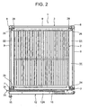
- Figure 2 is a plan view of the showcase 1 in a state in which a ceiling wall 1 lis removed
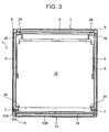
- Figure 3 is a plan view corresponding to Figure 2 in a state in which the ceiling wall 11, a net rack 12 and a bottom plate 13 are removed.
- a main body 3 of the showcase 1 of the embodiment comprises an insulated wall 4 made of foamed polyurethane, a bottom frame 6 made of a hard synthetic resin and mounted to an upper surface of the insulated wall 4, front support pillars 7,7 and rear support pillars 8,8 erected at four corners of the bottom frame 6, left and right and rear longitudinal transparent walls 9,9 and 9 made of transparent double glass which are supported by the support pillars 7,7 and 8,8 and the ceiling wall 11.
- a longitudinal door 12 (front door) as a transparent wall in which transparent double glass 12B is fitted into a surrounding sash 12A is pivotally supported by the right front support pillar 7 to rotate.
- a display room 14 is constituted by being surrounded with the transparent walls 9,9 and 9, the door 12, the ceiling wall 11, the bottom frame 6, and the centre bottom plate 13.
- the door 12 closes a front opening of the display room 4 to be freely opened.
- a reference numeral 15 is a grip mounted to a centre front in an up-and-down direction (longitudinal direction) of a non-pivotal supporting side (left side) of the sash 12A.
- a reference numeral 16 is a magnet gasket positioned around the front opening of the display chamber 14 and mounted to the main body 3, and bonded to the door 12 to seal it when the door 12 is closed.
- a machine chamber 18 around which panels 17 are mounted is constituted below the insulated wall 4.
- a compressor and a condenser (not shown) are installed to constitute a refrigerant circuit of a cooling device in the machine chamber 18.
- a cooling chamber 19 whose upper surface is open is constituted in the insulated wall 4 ( Figure 3).
- a cooler and a blower (not shown) which constitute the refrigerant circuit are installed in the cooling chamber 19.
- the bottom plate 13 is made of a hard synthetic resin similar to that of the bottom frame 6, and detachably mounted to the bottom frame 6 to close the upper opening of the cooling chamber 19.
- the bottom plate 13 is detachably mounted to the bottom frame 6 for assembling workability and maintenance. Depending on designing, however, they may be formed integrally. Irrespective of separate/integral formation, the bottom plate 13 constitutes a part of the bottom frame 6.
- a cold air outlet 21 is integrally formed from the front to the deep side on the right of the bottom plate 13.
- a cold air inlet 22 is integrally formed from the front to the deep side on the left.
- the cold air inlet 22 is communicated with a cold air suction side of the cooler in the cooling chamber 19, and the cold air outlet 21 is communicated with a cold air discharge side.
- Angles 23 are erected from the four corners of the bottom frame 6 ( Figure 1 shows front corners only).
- the front support pillars 7,7 and the rear support pillars 8,8 are connected to the angles 23 to be erected.
- Shelf supports 24,26 having a plurality of engaging holes formed up and down are integrally formed in the front support pillars 7,7 and the rear support pillars 8,8. Rear left and right sides are inserted and engaged with the engaging holes of the shelf supports 26,26 of the rear support pillars 8,8 and front left and right sides are fixed by screws to the engaging holes of the shelf supports 24,24 of the front support pillars 7,7 whereby a net rack 2 for displaying goods is hung in the display chamber 14.
- the net rack 2 is disposed at one state or a plurality of stages according to a use form.
- the net rack 2 is made of a wire of a steel material, or a hard synthetic resin, and formed roughly into a rectangular shape. Corresponding spaces G1,G2 are constituted above the cold air outlet 21 and the cold air inlet 22 between the right side and the right transparent wall 9 and between the left side and the left transparent wall 9. In this case, a centre of the left and right direction of the net rack 2 is displaced to the left (cold air inlet 22 side) and its mounting area is expanded to the left (cold air inlet 22 side), whereby the space G2 corresponding to a portion above the cold air inlet 22 is narrower than the space G1 corresponding to a portion above the cold air outlet 21.
- the space G1 of Figure 2 is similar to that in the left/right side of the net rack of the conventional showcase.
- a wiring receiving portion 28 is integrally formed inside the shelf support 26 (right side of the left rear support pillar 8, the left side of the right rear support pillar 8).
- the wiring receiving portion 28 receives a wiring for supplying power to a fluorescent lamp (illuminator, not shown) mounted to an inner surface upper end of the door 12.
- a front of the wiring receiving portion 28 is opened up and down, and a fin piece 29 made of a soft synthetic resin is integrally formed to narrow the opening in the rear support pillar 8 by double extrusion moulding.
- the fin piece 29 is pushed aside to insert the wiring through the opening.
- the fin piece 29 After the insertion, the fin piece 29 returns to narrow the opening. Thus, the wiring is prevented from coming out through the opening.
- a soft fin piece 31 is additionally formed integrally in the rear support pillar 8 (similar in the case of the front support pillar 7) to adhere to the transparent wall 9, whereby sealing and holding performance of the transparent wall 9 are secured.
- a heat insulating material (not shown) is mounted in the ceiling wall 11 and a groove for drawing around the wiring is formed in the heat insulating material.
- the wiring raised from the machine chamber 18 in the wiring receiving portion 28 of the rear support pillar 8 is passed through the groove to reach the fluorescent lamp of the door 12. In other words, no coupler is disposed between the fluorescent lamp and the wiring.
- the pivotal supporting side of the door 12 can be reversed left and right (pivotally supported on the right according to the embodiment) and the grooves of the ceiling wall 11 are symmetrically formed left and right to deal with reversal of the door 12.
- a locking device 32 is disposed in the showcase 1.
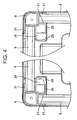
- the locking device 32 comprises main body side key metal fittings 33 mounted to the vicinity of the centre of the up-and-down direction (longitudinal direction) of the left front support pillar 7 which constitutes the main body 3, door side key metal fittings 34 mounted to the inner surface (side opposite the grip 15) in the vicinity of the centre of the up-and-down direction (longitudinal direction) of the non-pivotal support side (left in a closed state) of the sash 12A of the door 12 and a lock 36 ( Figure 2 and Figures 5 to 9).
- Both key metal fittings 33,34 are made of similarly shaped non-magnetic plates of stainless steel or the like, and upper ends thereof are mounted to the front support pillar 7 and the sash 12A by screws 37 to rotate.
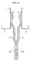
- the door side key metal fittings 34 are positioned above the main body side key metal fittings 33, usually drooped as shown in Figure 5 (during non-use) and positioned in a space between the main body 3 and the door 12 without mutual overlap thereof in the drooped state (in Figure 5 the door side key metal fittings 34 are virtual).
- Such arrangement eliminates the necessity of expanding the space between the main body 3 and the door 12.
- the main body side key metal fittings 33 are bent to the front into stair-form, and through-holes 33A are formed in tips thereof.
- the door side key metal fittings 34 are bent to the rear side into stair-form (main body side key metal fittings 33 are reversed and used) and through-holes 34A are similarly formed in tips thereof.
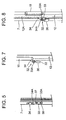
- the tips thereof are accordingly protruded from the space between the main body 3 and the door 12 outward (left), and the through-holes 33A,34A match each other outward (left) from the space between the main body 3 and the door 12 ( Figures 7,8).
- the tips of the main body side key metal fittings 33 come into close contact with the door 12 side (front side) of the tips of the door side key metal fittings 34 ( Figure 9).
- a projection 38 is formed in the front of the front support pillar 7, with which the through-hole 33A of the main body side key metal fittings 33 of the drooped state is engaged to be freely disengaged. Additionally, a projection (not shown) is formed in the sash 12A of the door 12, which is engaged with the through-hole 34A of the door side key metal fittings 34 of the drooped state to be freely disengaged. Accordingly, the key metal fittings 33,34 are maintained in the drooped states against shocks or a centrifugal force during the rotation of the door 12.
- the cooler when the compressor of the machine chamber 18 and the blower of the cooling chamber 19 are run, the cooler exhibits a cooling operation, and cold air heat-exchanged with the cooler is discharged from the right cold air outlet 21 upward by the blower.
- the cold air discharged from the cold air outlet 21 rises through the space G1 between the net rack 2 and the right transparent wall 9, lowers through the left space G2, and is sucked from the cold air inlet 22 to circulate in the display room 14.
- the goods on the net rack 2 hung in the display chamber 14 are cooled to a predetermined temperature.
- the space G2 is narrower than the space G1.
- the space G2 is a path through which the cold air after cooling in the display room 14 lowers, the cold air easily lowers by gravity, and cooling performance is not deteriorated.
- the key metal fittings 33,34 are protruded to the outside from the space between the main body 3 and the door 12 at the time of locking, and usually stored in the gap between the main body 3 and the door 12. Thus, an appearance is not damaged, and the key metal fittings 33,34 are not obstacles during normal door opening/closing. Especially because of the simple structure in which the key metal fittings 33,34 are mounted to the main body 3 or the door 12 to rotate, no cost increase occurs.
- the key metal fittings 33,34 are made of non-magnetic materials, no reduction occurs in a magnetic force of the magnet gasket 16. Especially since the key metal fittings 33,34 of the locking device 32 are mounted to the main body 3 in the vicinity of the centre of the non-pivotal support side of the door 12 or the door 12, bending of the upper and lower ends of the door 12 in the locked state can be limited to a minimum whereby safety can be improved more.
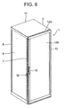
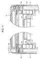
- FIGS 10 and 11 show another embodiment of the showcase 1 of the invention.
- the showcase 1 of the embodiment is constituted in a manner that front and rear surfaces of a display room 14 are opened, and the openings of the front and rear surfaces comprise doors.
- Main differences from the previous embodiment are shapes of a bottom frame and a rear support pillar, and a door mounted in place of the rear transparent wall.
- the bottom frame is denoted by a reference numeral 6A, the rear support pillar by 8A, and the door of the rear surface (rear door) by 41.
- the bottom frame 6A is formed into a shape capable of erecting rear support pillars 8A,8A at rear four corners by inserting a core into the same mould as that of the bottom frame 6.
- the rear support pillar 8A To mount the door 41 in the same size and to secure an aperture of a rear opening of the display room 14, the rear support pillar 8A is moved to the front side (door 12 side) to be mounted, and a shape thereof is different from that of the aforementioned rear support pillar 8. That is, in this case, the rear support pillar 8A exhibits a shape roughly similar to that of the front support pillar 7 and wiring receiving portions 43,44 are disposed side by side on two places of the front side in addition to a similar shelf support 42. In openings of the wiring receiving portions 43,44, fin pieces 46,47 made of soft synthetic resins are integrally formed by double extrusion. In this case, the wiring receiving portions 43,43 and 44,44 receive wiring for an electric heater when the display room 14 is heated to be used in addition to the wiring of the aforementioned fluorescent lamp.
- the door 41 is similar in structure to the front door 12 and an outer surface thereof excluding a grip 48 comes to the same position as that of the outer surface of the rear transparent wall 9 of the showcase 1 of Figure 1 (same outer size) because of the movement of the rear support pillars 8A,8A to the front side. Accordingly, substantially similar sizes are realised between the case of one door in Figure 1 and the case of two front and rear doors in Figure 10 to improve handling performance during transportation and storage. It is to be noted that the aforementioned locking device 32 is disposed also in the door 41.
- the showcase comprises the door pivotally supported on one side of the opening of the display room constituted in the main body so as to openably close the opening, the main body side key metal fittings rotatably mounted to the surface of the door side of the main body of the other side of the opening, and the door side key metal fittings rotatably mounted to the surface of the main body side on the non-pivotal support side of the door.
- the key metal fittings comprise the through-holes for lock insertion and are usually positioned in the space between the main body and the door, portions in which the through-holes are positioned are protruded outward from the space in the rotated state and the through-holes match each other in the state.
- the lock can be inserted into the through-holes in the matched state thereof to lock the door.
- the through-holes match each other in a state in which the positioning portions of the through-holes of the main body side key metal fittings are in close contact with the door side of the positioning portions of the through-holes of the door side key metal fittings.
- the key metal fittings are mounted to positions of no mutual overlap thereof in a state of being positioned in the space.
- the key metal fittings can be mounted without expanding the space between the main body and the door, and space efficiency can be increased.
- the key metal fittings are made of non-magnetic materials. Thus, no reduction occurs in the magnetic force of the magnet gasket or the like used for sealing the door.
- the main body and the door have holding structures capable of holding the state in which the key metal fittings are positioned in the space.
- the key metal fittings are improperly rotated by a centrifugal force, vibration or the like during the door opening/closing.
- the key metal fittings are mounted to the main body in the vicinity of the non-pivotal support side of the door, or the door.
- bending of the door end can be limited to a minimum and safety can be improved more.
Landscapes
- Physics & Mathematics (AREA)
- Thermal Sciences (AREA)
- Freezers Or Refrigerated Showcases (AREA)
- Refrigerator Housings (AREA)
Claims (5)
- Schrank, der ein Gehäuse (3), eine an dem Gehäuse angelenkt befestigte Tür (12) und eine Verriegelungseinrichtung (32) zum Sichern der Tür in einer geschlossenen Position umfasst, dadurch gekennzeichnet, dass die Verriegelungseinrichtung einen ersten und einen zweiten Arm (33, 34) umfasst, die an dem Gehäuse (3) bzw. an der Tür (12) schwenkbar befestigt sind, wobei der erste und der zweite Arm zwischen einer verstauten Stellung, in der sie in einem Raum zwischen der Tür und dem Gehäuse untergebracht sind, und einer Arbeitsstellung, in der sie von dem Gehäuse vorstehen, schwenkbar sind, wobei ein Loch (33A, 34A) in jedem Arm in der Arbeitsstellung auf das jeweils andere ausgerichtet ist, um zu ermöglichen, dass ein Schloss durch sie bewegt werden kann, um die Arme aneinander zu befestigen und um ein Öffnen der Tür zu verhindern.
- Schrank nach Anspruch 1, bei dem der Schwenkbefestigungspunkt eines Arms zu dem anderen Arm um eine Strecke versetzt ist, die größer als die Länge jedes Arms ist, wobei die Arme von ihrer Schwenkbefestigung übereinander liegend herabhängen, wenn sie sich in der verstauten Stellung befinden und nicht in Gebrauch sind und wenn die Tür geschlossen ist.
- Schrank nach Anspruch 1 oder Anspruch 2, bei dem jeder Arm eine Vorderseite und eine Rückseite besitzt, wobei die Rückseite jedes Arms an der Tür bzw. an dem Gehäuse befestigt ist, wobei die Arme so konfiguriert sind, dass sie sich in ihren Arbeitsstellungen kreuzen, so dass die Rückseite des ersten Arms in einem Kontakt mit der Rückseite des zweiten Arms in der Umgebung des Lochs ist.
- Schrank nach Anspruch 3, bei dem jeder Arm eine gekrümmte Form hat.
- Schrank nach einem vorhergehenden Anspruch, bei dem die Arme aus nicht magnetischen Werkstoffen hergestellt sind.
Applications Claiming Priority (2)
| Application Number | Priority Date | Filing Date | Title |
|---|---|---|---|
| JP2003399199A JP4097594B2 (ja) | 2003-11-28 | 2003-11-28 | ショーケース |
| JP2003399199 | 2003-11-28 |
Publications (2)
| Publication Number | Publication Date |
|---|---|
| EP1535542A1 EP1535542A1 (de) | 2005-06-01 |
| EP1535542B1 true EP1535542B1 (de) | 2007-01-03 |
Family
ID=34463878
Family Applications (1)
| Application Number | Title | Priority Date | Filing Date |
|---|---|---|---|
| EP20040257359 Expired - Lifetime EP1535542B1 (de) | 2003-11-28 | 2004-11-26 | Schaukasten |
Country Status (6)
| Country | Link |
|---|---|
| US (1) | US7314258B2 (de) |
| EP (1) | EP1535542B1 (de) |
| JP (1) | JP4097594B2 (de) |
| CN (1) | CN1270658C (de) |
| DE (1) | DE602004004045T2 (de) |
| ES (1) | ES2278284T3 (de) |
Cited By (2)
| Publication number | Priority date | Publication date | Assignee | Title |
|---|---|---|---|---|
| AU2008203824B2 (en) * | 2007-09-27 | 2013-06-27 | Sanyo Electric Co., Ltd. | Showcase |
| CN108724144A (zh) * | 2018-08-15 | 2018-11-02 | 安徽爱依特科技有限公司 | 防盗固定装置和具有该装置的商场机器人 |
Families Citing this family (8)
| Publication number | Priority date | Publication date | Assignee | Title |
|---|---|---|---|---|
| JP4675078B2 (ja) * | 2004-10-08 | 2011-04-20 | 三洋電機株式会社 | ショーケース |
| JP4895706B2 (ja) * | 2006-07-19 | 2012-03-14 | 三洋電機株式会社 | ショーケース |
| US20100117496A1 (en) * | 2008-11-10 | 2010-05-13 | C & L Marketing, Llc | Counter merchandiser that is expandable, adjustable, stackable and lightable |
| DE102010044761A1 (de) | 2010-09-08 | 2012-03-08 | Abb Ag | Elektrischer Schaltschrank |
| DE102010044760A1 (de) * | 2010-09-08 | 2012-03-08 | Abb Ag | Elektrischer Schaltschrank |
| US8677790B2 (en) * | 2011-12-16 | 2014-03-25 | Rex A. RAMSEY | Security enclosure and associated method |
| US9211004B2 (en) * | 2013-03-14 | 2015-12-15 | Kohler Co. | Medicine cabinet |
| CN103565174B (zh) * | 2013-11-21 | 2016-02-24 | 何慧敏 | 一种带丝冒和限位螺母的三角形商品展示柜 |
Family Cites Families (22)
| Publication number | Priority date | Publication date | Assignee | Title |
|---|---|---|---|---|
| US716118A (en) * | 1902-06-03 | 1902-12-16 | Paul Sorensen Scott | Fastener for show-cases. |
| US1336505A (en) * | 1916-03-04 | 1920-04-13 | Harry K Buggeln | Door-fastener |
| US1508384A (en) * | 1921-08-06 | 1924-09-16 | Sylvester A Drake | Hasp |
| US1781115A (en) * | 1925-07-18 | 1930-11-11 | Charles W Keplinger | Latch for service boxes |
| GB624399A (en) | 1947-06-13 | 1949-06-07 | Gen Electric Co Ltd | Improvements in or relating to fasteners |
| US2656948A (en) * | 1949-03-31 | 1953-10-27 | Gen Electric | Weatherproof enclosure for electrical devices |
| US2845295A (en) * | 1954-04-29 | 1958-07-29 | Clarke William | Door hasp |
| US3210142A (en) * | 1963-02-21 | 1965-10-05 | Mutschler Brothers Company | Music storage compartment |
| US3572064A (en) * | 1969-01-27 | 1971-03-23 | Ingersoll Locks Ltd | Padlocks |
| US3652114A (en) * | 1969-11-13 | 1972-03-28 | Best Look Corp | Security hasp |
| US4761975A (en) * | 1987-06-05 | 1988-08-09 | Unisys Corporation | Module security locking device |
| US5092143A (en) * | 1991-08-29 | 1992-03-03 | Rumbles Wayne A | Lockable enclosure having a tamper-proof locking assembly |
| JP2680760B2 (ja) | 1991-11-20 | 1997-11-19 | 三洋電機株式会社 | ショーケース |
| US5400622A (en) * | 1993-05-11 | 1995-03-28 | Leonard Bloom | Locking device for floppy disk drive |
| US5429430A (en) * | 1993-12-29 | 1995-07-04 | Johnson; Joseph V. | Display system and method |
| JP3524663B2 (ja) | 1995-12-22 | 2004-05-10 | 三洋電機株式会社 | ショーケース |
| US5848500A (en) * | 1997-01-07 | 1998-12-15 | Eastman Kodak Company | Light-tight enclosure and joint connectors for enclosure framework |
| DE29711737U1 (de) * | 1997-07-04 | 1998-10-29 | Ramsauer, Dieter, 42555 Velbert | Durch Vorhängeschloß sichtbare Schwenkhebelbetätigung für den Verschluß von Schaltschranktüren o.dgl. |
| US5907962A (en) * | 1997-11-10 | 1999-06-01 | Silicon Graphics, Inc. | Latching assembly for a computer |
| US6626508B1 (en) | 2000-02-07 | 2003-09-30 | H & R Industries, Inc. | Cabinet cooler |
| US6238029B1 (en) * | 2000-04-11 | 2001-05-29 | Ads, The Power Resource, Inc. | Universal electronics cabinet |
| US6591641B1 (en) * | 2002-03-25 | 2003-07-15 | Freight Securities, Inc. | Locking device for lockrod-type cargo-container closures |
-
2003
- 2003-11-28 JP JP2003399199A patent/JP4097594B2/ja not_active Expired - Lifetime
-
2004
- 2004-11-09 CN CNB2004100923395A patent/CN1270658C/zh not_active Expired - Lifetime
- 2004-11-15 US US10/986,900 patent/US7314258B2/en not_active Expired - Lifetime
- 2004-11-26 EP EP20040257359 patent/EP1535542B1/de not_active Expired - Lifetime
- 2004-11-26 DE DE200460004045 patent/DE602004004045T2/de not_active Expired - Lifetime
- 2004-11-26 ES ES04257359T patent/ES2278284T3/es not_active Expired - Lifetime
Cited By (2)
| Publication number | Priority date | Publication date | Assignee | Title |
|---|---|---|---|---|
| AU2008203824B2 (en) * | 2007-09-27 | 2013-06-27 | Sanyo Electric Co., Ltd. | Showcase |
| CN108724144A (zh) * | 2018-08-15 | 2018-11-02 | 安徽爱依特科技有限公司 | 防盗固定装置和具有该装置的商场机器人 |
Also Published As
| Publication number | Publication date |
|---|---|
| CN1270658C (zh) | 2006-08-23 |
| DE602004004045T2 (de) | 2007-05-31 |
| JP4097594B2 (ja) | 2008-06-11 |
| US20050115286A1 (en) | 2005-06-02 |
| US7314258B2 (en) | 2008-01-01 |
| EP1535542A1 (de) | 2005-06-01 |
| CN1620964A (zh) | 2005-06-01 |
| JP2005152528A (ja) | 2005-06-16 |
| ES2278284T3 (es) | 2007-08-01 |
| DE602004004045D1 (de) | 2007-02-15 |
Similar Documents
| Publication | Publication Date | Title |
|---|---|---|
| EP1535542B1 (de) | Schaukasten | |
| US7162885B2 (en) | Showcase | |
| US20060049726A1 (en) | Showcase | |
| JP5603620B2 (ja) | 冷却貯蔵庫 | |
| WO2004029528A1 (en) | Door assembly for a refrigerator | |
| JP4598171B2 (ja) | 棚柱付き冷蔵ショーケース | |
| KR20080076657A (ko) | 공기조화기 | |
| US7228697B2 (en) | Integrated air conditioner having condenser casing | |
| JP2000310475A (ja) | 冷却装置 | |
| EP4524498A1 (de) | Kühlschrank | |
| JP4156952B2 (ja) | 冷却貯蔵庫 | |
| KR0126830B1 (ko) | 4도어 쇼케이스 | |
| JPH112482A (ja) | 冷蔵庫 | |
| JPH09280717A (ja) | 冷却貯蔵庫 | |
| JP4141338B2 (ja) | 低温ショーケース | |
| JPH09273856A (ja) | 冷却貯蔵庫 | |
| KR100600069B1 (ko) | 공기조화기 | |
| JP5421764B2 (ja) | 冷却貯蔵庫 | |
| JP2012154585A (ja) | 冷却貯蔵庫 | |
| KR100238655B1 (ko) | 냉장고의 도어 결합구조 | |
| JP3670170B2 (ja) | 棚受け支柱 | |
| JP2007107760A (ja) | 冷却貯蔵庫 | |
| JP2567746B2 (ja) | 低温ショ−ケ−ス | |
| KR20000038045A (ko) | 쇼케이스 기계실 전면그릴구조 | |
| JP2000258035A (ja) | 冷蔵庫 |
Legal Events
| Date | Code | Title | Description |
|---|---|---|---|
| PUAI | Public reference made under article 153(3) epc to a published international application that has entered the european phase |
Free format text: ORIGINAL CODE: 0009012 |
|
| AK | Designated contracting states |
Kind code of ref document: A1 Designated state(s): AT BE BG CH CY CZ DE DK EE ES FI FR GB GR HU IE IS IT LI LU MC NL PL PT RO SE SI SK TR |
|
| AX | Request for extension of the european patent |
Extension state: AL HR LT LV MK YU |
|
| 17P | Request for examination filed |
Effective date: 20050702 |
|
| GRAP | Despatch of communication of intention to grant a patent |
Free format text: ORIGINAL CODE: EPIDOSNIGR1 |
|
| AKX | Designation fees paid |
Designated state(s): DE ES FR GB IT |
|
| GRAS | Grant fee paid |
Free format text: ORIGINAL CODE: EPIDOSNIGR3 |
|
| GRAA | (expected) grant |
Free format text: ORIGINAL CODE: 0009210 |
|
| AK | Designated contracting states |
Kind code of ref document: B1 Designated state(s): DE ES FR GB IT |
|
| REG | Reference to a national code |
Ref country code: GB Ref legal event code: FG4D |
|
| REF | Corresponds to: |
Ref document number: 602004004045 Country of ref document: DE Date of ref document: 20070215 Kind code of ref document: P |
|
| ET | Fr: translation filed | ||
| REG | Reference to a national code |
Ref country code: ES Ref legal event code: FG2A Ref document number: 2278284 Country of ref document: ES Kind code of ref document: T3 |
|
| PLBE | No opposition filed within time limit |
Free format text: ORIGINAL CODE: 0009261 |
|
| STAA | Information on the status of an ep patent application or granted ep patent |
Free format text: STATUS: NO OPPOSITION FILED WITHIN TIME LIMIT |
|
| 26N | No opposition filed |
Effective date: 20071005 |
|
| REG | Reference to a national code |
Ref country code: FR Ref legal event code: PLFP Year of fee payment: 12 |
|
| PGFP | Annual fee paid to national office [announced via postgrant information from national office to epo] |
Ref country code: GB Payment date: 20151125 Year of fee payment: 12 Ref country code: DE Payment date: 20151118 Year of fee payment: 12 Ref country code: IT Payment date: 20151124 Year of fee payment: 12 |
|
| PGFP | Annual fee paid to national office [announced via postgrant information from national office to epo] |
Ref country code: FR Payment date: 20151008 Year of fee payment: 12 Ref country code: ES Payment date: 20151014 Year of fee payment: 12 |
|
| REG | Reference to a national code |
Ref country code: DE Ref legal event code: R119 Ref document number: 602004004045 Country of ref document: DE |
|
| GBPC | Gb: european patent ceased through non-payment of renewal fee |
Effective date: 20161126 |
|
| REG | Reference to a national code |
Ref country code: FR Ref legal event code: ST Effective date: 20170731 |
|
| PG25 | Lapsed in a contracting state [announced via postgrant information from national office to epo] |
Ref country code: IT Free format text: LAPSE BECAUSE OF NON-PAYMENT OF DUE FEES Effective date: 20161126 Ref country code: FR Free format text: LAPSE BECAUSE OF NON-PAYMENT OF DUE FEES Effective date: 20161130 |
|
| PG25 | Lapsed in a contracting state [announced via postgrant information from national office to epo] |
Ref country code: DE Free format text: LAPSE BECAUSE OF NON-PAYMENT OF DUE FEES Effective date: 20170601 Ref country code: GB Free format text: LAPSE BECAUSE OF NON-PAYMENT OF DUE FEES Effective date: 20161126 |
|
| PG25 | Lapsed in a contracting state [announced via postgrant information from national office to epo] |
Ref country code: ES Free format text: LAPSE BECAUSE OF NON-PAYMENT OF DUE FEES Effective date: 20161127 |
|
| REG | Reference to a national code |
Ref country code: ES Ref legal event code: FD2A Effective date: 20181120 |