EP1535115B1 - Procede et dispositif pour produire des structures exposees - Google Patents
Procede et dispositif pour produire des structures exposees Download PDFInfo
- Publication number
- EP1535115B1 EP1535115B1 EP03798112A EP03798112A EP1535115B1 EP 1535115 B1 EP1535115 B1 EP 1535115B1 EP 03798112 A EP03798112 A EP 03798112A EP 03798112 A EP03798112 A EP 03798112A EP 1535115 B1 EP1535115 B1 EP 1535115B1
- Authority
- EP
- European Patent Office
- Prior art keywords
- exposure
- control
- control memory
- lines
- data
- Prior art date
- Legal status (The legal status is an assumption and is not a legal conclusion. Google has not performed a legal analysis and makes no representation as to the accuracy of the status listed.)
- Expired - Lifetime
Links
Images


Classifications
-
- G—PHYSICS
- G03—PHOTOGRAPHY; CINEMATOGRAPHY; ANALOGOUS TECHNIQUES USING WAVES OTHER THAN OPTICAL WAVES; ELECTROGRAPHY; HOLOGRAPHY
- G03F—PHOTOMECHANICAL PRODUCTION OF TEXTURED OR PATTERNED SURFACES, e.g. FOR PRINTING, FOR PROCESSING OF SEMICONDUCTOR DEVICES; MATERIALS THEREFOR; ORIGINALS THEREFOR; APPARATUS SPECIALLY ADAPTED THEREFOR
- G03F7/00—Photomechanical, e.g. photolithographic, production of textured or patterned surfaces, e.g. printing surfaces; Materials therefor, e.g. comprising photoresists; Apparatus specially adapted therefor
- G03F7/70—Microphotolithographic exposure; Apparatus therefor
- G03F7/70483—Information management; Active and passive control; Testing; Wafer monitoring, e.g. pattern monitoring
- G03F7/70491—Information management, e.g. software; Active and passive control, e.g. details of controlling exposure processes or exposure tool monitoring processes
- G03F7/70525—Controlling normal operating mode, e.g. matching different apparatus, remote control or prediction of failure
-
- G—PHYSICS
- G03—PHOTOGRAPHY; CINEMATOGRAPHY; ANALOGOUS TECHNIQUES USING WAVES OTHER THAN OPTICAL WAVES; ELECTROGRAPHY; HOLOGRAPHY
- G03F—PHOTOMECHANICAL PRODUCTION OF TEXTURED OR PATTERNED SURFACES, e.g. FOR PRINTING, FOR PROCESSING OF SEMICONDUCTOR DEVICES; MATERIALS THEREFOR; ORIGINALS THEREFOR; APPARATUS SPECIALLY ADAPTED THEREFOR
- G03F7/00—Photomechanical, e.g. photolithographic, production of textured or patterned surfaces, e.g. printing surfaces; Materials therefor, e.g. comprising photoresists; Apparatus specially adapted therefor
- G03F7/70—Microphotolithographic exposure; Apparatus therefor
- G03F7/70383—Direct write, i.e. pattern is written directly without the use of a mask by one or multiple beams
- G03F7/704—Scanned exposure beam, e.g. raster-, rotary- and vector scanning
-
- G—PHYSICS
- G03—PHOTOGRAPHY; CINEMATOGRAPHY; ANALOGOUS TECHNIQUES USING WAVES OTHER THAN OPTICAL WAVES; ELECTROGRAPHY; HOLOGRAPHY
- G03F—PHOTOMECHANICAL PRODUCTION OF TEXTURED OR PATTERNED SURFACES, e.g. FOR PRINTING, FOR PROCESSING OF SEMICONDUCTOR DEVICES; MATERIALS THEREFOR; ORIGINALS THEREFOR; APPARATUS SPECIALLY ADAPTED THEREFOR
- G03F7/00—Photomechanical, e.g. photolithographic, production of textured or patterned surfaces, e.g. printing surfaces; Materials therefor, e.g. comprising photoresists; Apparatus specially adapted therefor
- G03F7/70—Microphotolithographic exposure; Apparatus therefor
- G03F7/70425—Imaging strategies, e.g. for increasing throughput or resolution, printing product fields larger than the image field or compensating lithography- or non-lithography errors, e.g. proximity correction, mix-and-match, stitching or double patterning
Definitions
- the invention relates to a method for producing exposed structures on a multiplicity of subassemblies arranged on at least one substrate body by means of an exposure device in which at least one substrate body arranged on a substrate carrier and the exposure device are moved relative to one another in a main direction and transversely thereto in a secondary direction , wherein identical structures are produced on at least a part of the assemblies.
- the invention is therefore an object of the invention to improve a method for producing exposed structures of the generic type such that it works as efficiently as possible.
- each of the identical structures by exposing the substrate body in the region of each provided assembly within a plurality of extending in the main direction and adjacent macro-lines in the secondary direction in that each of the macro-lines comprises a plurality of lines extending in the main direction and juxtaposed in the secondary direction, that with the exposure device in a single pass through an exposure path all detected by this exposure path and to be provided with identical structures in the same macro line of the Be exposed in a plurality of macro-lines that the exposure device has a plurality of light sources and a substantially simultaneously controlling this control with a control memory which is constructed so that from this already stored data sets of the macro line, is illuminated in the area can be read out while data records of another macro line are stored.
- control memory can thereby be used efficiently, that on the one hand, the data sets used for the exposure of the corresponding macro line can be read, while records of another macro line can be stored and that also the time during in which the data records used for the exposure are read, is kept as large as possible that the exposure path extends over a plurality of modules, so that in turn the largest possible period for storing data sets of the further macro-line provided for the subsequent exposure is available.
- An exposure path is to be understood as meaning the path which extends beyond all those subassemblies in which exposure takes place in the region of the same macro-lines, whereby an actual exposure of the substrate does not always have to take place on the path section between successive subassemblies or on other path sections.
- a method according to the invention is particularly advantageous when the exposure path is selected at least so long that the time for traversing it corresponds at least to the time required for storing at least half of the data records of the further macro line in the control memory.
- control memory size to be chosen so that it is capable of storing approximately half of the macro-lines required for one type of assembly, since during the Reading these macro lines for exposure in the same other macro lines can be stored respectively.
- control memory An even greater reduction of the control memory can be achieved if the exposure path is selected at least so long that the time for traversing it is at least equal to the time required to store at least two thirds of the data sets of the further macro line in the control memory.
- a particularly optimal configuration provides that the exposure path is chosen at least as long that the time for traversing it corresponds at least to the time required for storing the data records of the further macro-line in the control memory.
- the exposure path extends only over a substrate body.
- the exposure path extends over a plurality of substrate bodies.
- the exposure path is exclusively and rectilinear in the main direction, since then only one movement in the main direction is required for an exposure path and a further exposure path can be started after a subsequent movement in the secondary direction.
- a particularly preferred solution for lengthening the exposure path is that the exposure path is meander-shaped, with the Meander preferably at least in the main direction rectilinear sections have.
- the assemblies are arranged in parallel to the main direction extending rows on the substrate bodies, since then the exposure paths can be conveniently set so that they have rectilinear in the main direction extending sections.
- an arrangement in which the exposure path comprises at least one row of assemblies is particularly efficient.
- the exposure path can then be set if it comprises all arranged in a main row in the main row assemblies on a substrate support, thus with a simple way of guiding the exposure path as long as possible and thus the largest possible time for passing through the exposure path to reach.
- the plurality of rows of assemblies are adjacent.
- a preferred embodiment of a solution according to the invention provides that the exposure path detects a series of assemblies and then alternates transversely to the main direction on a further series of modules and detects them.
- the exposure path passes through this further series of assemblies in the reverse direction than the one row of assemblies.
- the entire plurality of light sources of the exposure device is provided for exposing the plurality of lines of a macro line, so that the exposure device in the It is able to perform the exposure with all available light sources in the area of a macro line.
- the entire plurality of light sources of the exposure device is operated simultaneously via the controller in order to be able to carry out the exposure in the region of the macro line with the greatest possible speed in the main direction and thus the greatest possible efficiency.
- a particularly favorable conception which on the one hand ensures that the data sets for the plurality of macro-lines of at least one module are provided, but on the other hand also the fastest possible access to the data records of the macro-line, in the area which is currently being exposed, provides for the control memory to be used over an interface with at least one main memory which stores at least the records of the plurality of macro-lines of an assembly communicates.
- control memory comprises a plurality of control memory modules and that the controller simultaneously communicates with the plurality of control memory modules of the control memory.
- control memory modules With regard to the summary and the use of the multiple control memory modules, it has proven to be particularly advantageous if a plurality of control memory modules are combined by means of a control module to a control memory unit and communicate with them via the controller.
- control memory modules Preferably, it is likewise provided that storage of data records from the main memory in the control memory modules takes place via the control modules.
- the data records are stored in the main memory in a volume-reduced data format and that a conversion to a machine-oriented data format is carried out before the data sets are read into the control memory.
- a volume reduced data format is a vector data format. But it can also be another volume-reduced data format.
- the machine-near data format is preferably a pixel data format which is particularly suitable for controlling the individual light sources, but another machine-oriented data format is also conceivable.
- the conversion of the data format could be done, for example, directly when reading from the main memory. However, it is particularly favorable if the conversion of the data format takes place immediately before a data transfer to the control module in order to be able to carry out the data transmission with the volume-reduced data format which shortens the transmission time until the data is transferred to the control module.
- control memory is divided into a plurality of control memory units and thus receives the control for the simultaneous activation of the light sources data sets from a plurality of control memory units.
- control memory associated with the controller is designed to store at least two macro-lines.
- control memory associated with the controller for the storage of less than half of the plurality of macro-lines of a module is designed to realize the control memory as cost-effectively.
- control memory associated with the controller is designed to store less than a quarter of the plurality of macro-lines of a module.
- the plurality of light sources used according to the invention to perform the exposure in the region of a macro-line could be designed with respect to the realization of the drive of the same so that the plurality of light sources learns no more subdivision.
- the drive of the light sources can be made more efficient if the plurality of light sources is formed of a plurality of light source groups, each light source group in turn having a plurality of light sources.
- a particularly advantageous control concept provides that each light source group is assigned its own group control and the light sources of the light source group are controlled exclusively and independently of the other light source groups by this group control.
- a particularly advantageous solution provides that the number of structure lines which define the structure of the assembly is smaller than the total number of lines in which by means of the exposure device Exposure can be performed in the range of the assembly, and that a fine positioning in the secondary direction by a variation of the assignment of the structure lines to the exposable with the exposure device lines.
- the advantage of this solution is the fact that at least the fine positioning of rectilinear, parallel tracks in the secondary direction does not have to be effected by a physical displacement of the substrate carrier, but by the assignment of the structure lines to the exposable with the exposure means of the software, so that the can be avoided with a physical positioning due to the inertia-related delay effects, at least with regard to this fine positioning. It is the fine positioning by means of the software in a more comprehensive manner, for example, to perform non-rectilinear or non-parallel paths.
- the fine positioning can be implemented particularly quickly if the change in the assignment is carried out by the controller for the light sources, since a correction with a time constant which is very small can be implemented immediately before the actual exposure of the substrate.
- a particularly favorable solution provides that in the control memory for each macro line records of a number of structure lines are stored, which is greater than the plurality of exposure in the range of this macro line by the exposure means, so that in the area of each macro line directly a correction of Position errors of the substrate body in the secondary direction is executable.
- the group control records are provided for a subset of the structure lines of the structure to be exposed, wherein the number of structure lines of the subset is greater than that of the light source group an imageable number of lines within a group strip.
- the data sets of subsets of the structure lines of the structure to be exposed to the adjacent light source groups comprise structure lines which are contained in both subsets.
- the structure lines contained in both subsets form an overlap region, the remaining structure lines of the subsets each lying on opposite sides of the overlapping region.
- each line it would be conceivable to provide a light source for each line to be exposed. It is particularly favorable, however, if with each light source a line of lines comprising several lines can be exposed.
- a further advantageous solution provides that, in the case of two exposure devices, the relative movements in the secondary direction take place in opposite directions in order likewise to compensate for the effects of the mass inertia.
- a particularly favorable solution provides that four exposure devices are used and that in pairs, the relative movements in the main direction and the relative movements in the secondary direction take place in opposite directions.
- the invention also relates to a device for producing exposed structures on at least one substrate body by means of an exposure device in which at least one substrate body arranged on a substrate carrier and the exposure device are movable relative to one another in a main direction and transversely thereto in a secondary direction.
- the input asked task is achieved in this device, according to the invention that the exposed structures by exposing the substrate body within a plurality of extending in the main direction and in the secondary direction adjacent macro line that each of the macro-lines comprises a plurality of lines extending in the main direction and adjacent to each other in the secondary direction, and in that the exposure device comprises a plurality of light sources and a controller which controls them substantially simultaneously with a control memory which is designed such that from this already stored data sets of the macro line, in the area of which is exposed, can be read while records of another macro line can be stored.
- the apparatus of the present invention not only serves to perform the method of the present invention described above, but can also be used for easy exposure in the production of photolithographic masks or large-sized packages, and is therefore not limited to exposing exposed structures to a plurality of at least one Substrate bodies arranged assemblies are to be produced by means of the exposure device.
- the advantage of the device according to the invention is still that in the device according to the invention the exposed structure can be produced efficiently.
- the device according to the invention can also be used to produce exposed structures on a multiplicity of at least one substrate body arranged assemblies using the exposure device, wherein on at least a portion of the modules identical structures are produced.
- each of the identical structures is produced by exposing the substrate body in the region of the respectively provided assembly within a plurality of macro-lines extending in the main direction and in the secondary direction the macro-lines comprises a plurality of lines extending in the main direction and juxtaposed in the secondary direction, wherein with the exposure device in a single pass through an exposure path all detected by this exposure path and to be provided with identical structures assemblies in the same macro-line of the plurality of macro-lines can be exposed and wherein the exposure device comprises a plurality of light sources and a controller which controls them substantially simultaneously with a control memory, which is thus made is formed, that are readable on this already stored data sets of the macro line, in whose area is exposed, while records of another macro line can be stored.
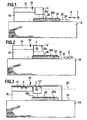
- An exemplary embodiment of a device according to the invention for exposing substrate materials shown in FIG. 1 comprises an exposure device 10, which comprises an optical head 12 and an exposure control 14 associated therewith.
- the exposure device 10 is supported, for example, by means of a bridge body 16 on a foundation body 18.
- the bridge body 16 engages over a movement region 20, in which a support carriage 22 is movable relative to the foundation body 18, wherein the support carriage 22 on a guide plane 24 of the foundation body 18 is slidably guided, for example by air cushion, as in German Patent Application DE 10212344 A1.
- the support carriage 22 by not shown in FIG. 1 drive units for the support carriage 22, for example, both in an X direction as the main direction and in a direction perpendicular to this Y direction as a secondary direction, both parallel to the guide plane 24, within the Movement range 20 movable and exactly relative to the exposure device 10, in particular to the optical head 12 thereof positioned.
- the movement region 20 for the carrier carriage 22 is dimensioned so that the substrate body 28 can be exposed on its entire substrate surface 30.
- the substrate carrier 26 stationary and to move the optical head 12 "relative to the bridge body 16" in the X and Y direction in a movement region 20 "relative to the substrate carrier 26, also around the entire surface 30 of the respective substrate to expose, as shown in Fig. 3.
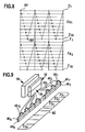
- Such a substrate body 28 is for example - as shown in Fig. 4 - a so-called wafer, as it is used in semiconductor technology.
- the exposure of the wafer is done to create defined structures 32 thereon, one or more of such structures 32 then providing an assembly 34, such as an electrical, electronic, or optical device.
- the defined structures 32 do not extend over the entire surface 30 of the substrate body 28, but as a rule a multiplicity of assemblies 34 can be produced on such a substrate body 28, wherein in particular all the assemblies 34 are constructed by the same structures 32.
- these are preferably arranged in rows 36 on the substrate body 28, wherein the rows 36 preferably extend parallel to the main direction X and perpendicular to the secondary direction Y.
- a relative movement between the exposure device 10 and the substrate support 26 along the main direction X is generated, so that preferably all assemblies 34 one of the rows 36 in a train by the relative movement in the main direction X over run and thereby exposed and subsequently after an offset in the secondary direction Y again a driving over and exposing all assemblies 34 one of the rows 36 takes place.
- Fabrication of the structures is accomplished, as shown in FIG. 5, by exposing the surface 30 of the substrate body within the area of the respective assemblies 34 in a grid 38 consisting of individual grid points RP having a grid spacing RX and RY from each other, this grid spacing RX, RY is on the order of 50 nanometers, for example.
- Each raster point RP represents a center of a pixel patch PF which, starting from the center RP, has a pixel extent PA which is a multiple of the raster spacing RX, RY, for example up to approximately five times the same.
- contiguous structures 32 can be produced in which adjacent pixel spots PF overlap several times, for example five times, so that relatively straight-lined structure edges 40 of the exposed one overlap Structure 32 of successive pixel patches PF at longitudinal successive raster points RP sitting pixel patches PF generate.
- the grid points RP in rows Z are arranged parallel to the rows Z1 to Z10 to the main direction X and perpendicular to the secondary direction Y and thus also parallel to the rows 36.
- the provided for generating a pixel spot PF exposure beam 42 in the secondary direction Y is movable over the grid 38 so that the pixel spot PF with its center, for example on each of 10th Lines Z1 to Z10 can be positioned.
- a light source 44 for example in the form of a laser diode, provided whose light beam is deflected by a deflection unit 46 combined with a microscope optics 48 so that the exposure beam 42 can generate a pixel spot PF on the surface 30 of the substrate whose center can be positioned on each of the lines Z1 to Z10 in the respective grid point RP (FIG. 7).
- the lines Z1 to Z10 detectable by the light source 44 with the exposure beam 42 thus form a line strip ZS extending in the main direction X, as shown in FIG.
- a plurality of light sources 44 1 to 44 N with corresponding deflection units 46 1 to 46 N and microscope optics 48 1 to 48 N are provided in the optical head 12, all of which are simultaneously operable in a relative movement between the optical head 12 and the substrate carrier 26 in the main direction X.
- a large number N of light sources 44 with deflection units 46 and microscope optics 48 are used.
- Useful are numbers of some one hundred light sources 44, for example 504 light sources, which are thus able to make an exposure through a pixel gap PF when moving in the main direction X in the range of 5040 lines Z.
- a plurality of gray levels are provided for a pixel spot PF, for example more than 10 gray levels, preferably 32 gray levels per pixel spot PF.
- the exposure device 10 provided with, for example, several hundred light sources 44 is also unable to make an exposure in the region of all lines Z required for the production of the structure 32 of the assembly 34.
- the to 44 N exposable in the main direction X with the light sources 44 1 rows by a single crossing of the assembly 34 encompassed by the sets of lines ZS1 to ZSN, are referred to as macro line MZ, so that all the exposure required for the structure 32 of the module 34 Lines, as shown in Fig. 7 and 8, a total exposure of the assembly 34 in the range of M juxtaposed macro-lines MZ is required.
- controller 50 driving the light sources 44 must have quick access to the control memory 52, it would be, if a total of M macro-lines. MZ must be required to store in the control memory 52, the records for all M macro-lines MZ of the assembly 34.
- control memory 52 would have to be designed very large and thus would be costly.
- control memory 52 is formed so that on the one hand records for exposing the lines Z can be read by the controller for the light sources 44, but at the same time records from a main memory 54 of a higher-level computer, such as the host computer, are read. It is thereby possible, during the exposure in the region of a macro-line MZ and thus of the read-out of the data sets for this exposure, to simultaneously read in data records for a further macro-line MZ.
- control memory 52 depends on how long the time is required for an exposure path W, and how fast the data sets from the main memory 54 can be stored in the control memory 52.
- a first exposure path W1 for an exposure in the region of the first macro-line MZ 1 placed so that it detects the assemblies 34 which are arranged along a row 36, wherein the assembly 34 the Assemblies on a substrate body 28 are.
- control memory 52 is only to be chosen so large that it can store slightly more than half of the macro-lines MZ, if the transfer of the records of the main memory 54 in the control memory 52 and the storing can be made so fast that it is possible during the passage of the exposure path W1 from its beginning W1A to its end W1E, which detects all assemblies 34 along the row 36x, about half of the records of another, not yet stored in the control memory 52 Macro line MZ store.
- control memory 52 can be further reduced if the exposure path W is prolonged.
- the exposure path W'1 shown in Fig. 11 which detects from its beginning W'IA to its end W'1E the assemblies 34 arranged along two rows 36Y and 36Y + 1, then at the same speed In the main direction X and the same data transfer rate from the main memory 54 to the control memory 52, which was assumed above, it is already possible to store the data records of an entire further macro-line MZ in the control memory 52 during the passage of the exposure path W'1.
- control memory 52 only has to be chosen so large that it is able to store the data records of two macro-lines MZ, namely the data records which are read out in the course of the exposure path W 'for the respective macro-line MZ and the data records, which are read from the main memory 54 in the control memory 52 and stored for the next to be exposed macro-line MZ.
- the time required for an exposure path can be increased even further by disposing on the substrate support 26 not just one substrate body 28 but two substrate bodies 28a, b, the defined structures 32 of the assemblies 34 being identical are (Fig. 12).
- assemblies 34 on both substrate bodies 28a, b to be arranged so that they each lie in a common row 36.
- the time required to pass through the respective exposure path W in this case the exposure path W1 ", can be increased by the exposure path W1" detecting the assemblies 34 along the row 36 on both substrate bodies 28a, b are arranged.
- the time for traversing the exposure path W1 "from its beginning W1" A to its end W1 "E is necessarily larger than the time for traversing the exposure path W1 shown in Fig. 12, and is preferably on the order of the time for the Passing through the exposure path W1 ", shown in Fig. 12, but with the advantage that for passing through the exposure path W1" only a rectilinear movement in the main direction X is required and no movement in the secondary direction Y, so that, for example, for the opposite movement in the main direction X already writing a further macro-line MZ can be provided.
- the assemblies 34 of two substrate bodies 28a, b are exposed in the region of a macro-line MZ along the exposure path W1 ", which detects the assemblies 34 from two, for example, adjacent rows 36W and 36W + 1 and thus at least twice as long as the exposure path W "is.
- an exposure path W1 "" can be selected which provides in that the same macro-line MZ, for example the macro-line MZ 1 on all assemblies 34, is detected by all the substrate bodies 28a, b of the substrate carrier 26 from the exposure path W1 "".
- each light source group 64 comprising about 20 to 40 light sources, preferably 25 to 35 light sources.
- each light source group 28 includes light sources 44 (FIG. 14).
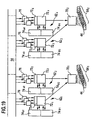
- the controller 50 is divided into individual group controllers 70, each group controller 70 operating independently of the other group controller to simultaneously drive the light source group 64 associated therewith, preferably drivers of the individual light sources 44 of the light source group 64.
- control memory 52 is also divided.
- the control memory 52 is formed of a plurality of control storage units 62, each control storage unit 62 being a control module 72, which cooperates with a plurality of control memory modules 74, preferably designed as a RAM.
- each control module 72 cooperates with two control memory modules 74a, b or an even larger number of control memory modules 74 (FIG. 14).
- the control module 72 itself is preferably designed as a so-called RAM FPGA and serves, on the one hand, to read out data records from the respective control memory module 74 and at the same time, however, also to read in data sets therein.
- interface modules 76 in particular USB's, which are provided between the main memory 54 and the respective control module 72 for parallel transmission of the data sets from the main memory 54, wherein the control module 72 in turn then turn these records into the Control memory modules 74 stores.
- Each of the independently operating group controllers 70 is preferably not associated with only one controller memory unit 62, but a plurality of controller memory units 62 are provided per group controller 70.
- each of the group controllers 70 1 and 70 2 are respectively assigned two control memory units 62 1 and 62 2 and 62 3 and 62 4 , respectively.
- Each of the light source groups 64 is thus able to perform exposure in a part of the plurality V of lines Z of a macro-line MZ.
- each light source 44 is preferably assigned a line strip ZS comprising a plurality of lines Z
- the number T of the lines Z in which an exposure can be carried out by means of a light source group 64 corresponds to the number of lines Z per line strip ZS multiplied by Number Q of the light sources 44 per light source group 64.
- the number T of lines Z which is thus assigned to a light source group 64, forms an overall group strip GS extending in the main direction X.
- the group strips GS can be arranged so that, in the case of adjoining group strips, for example the group strips GS 4 and GS 5 in FIG. 15, the first line ZE 5 of the following on the group strip GS 4 group strip GS 5 in the grid spacing RY from the last line ZL 4 of the group strip GS 4 is arranged.
- a particularly advantageous embodiment provides that with the support carriage 22 is a coarse positioning in the secondary direction Y, while a parallel positioning in the Y direction comprehensive fine positioning of the structures 32 relative to each other by different assignment of the data sets from the structure 32 defining structure lines SZ to the individual lines Z takes place, in which is exposable.
- the total number G of lines Z, in which exposure of the substrate 28 in the region of the respective assembly 34 with the exposure device 10 is possible is greater than the total number S of structure lines SZ, in the region of which exposure is required. to create the defined structure 32.
- the controller 50 to associate the first structure line SZ 1, for example the eleventh line Z 11 of the macro line MZ, in which an exposure can be carried out, as shown in FIG. 16 by dashed arrows, or, as shown in FIG. 14 by dotted arrows, the first structure line SZ 1 of the 75th line Z 75 of the macro line MZ, in which an exposure is feasible assign.
- variable assignment of the structure lines SZ to actually write lines Z by the controller has - when only the macro lines are considered - the consequence that the number of the control memory 52 to be stored records increases, since for each between the first and last macro line MZ1 and MZM lying macro line MZ not only the data records for the total number V of actually to be written lines Z of the macro line must be stored, but also the both sides of the respective macro line MZ adjacent number U of lines, where the number U of lines of half maximum possible Displacement of the assignment of structure lines SZ and lines corresponds, which can still be changed by the controller 50 when driving the light sources 44 yet.
- each of the group controllers 70 may not only be provided with a subset of data sets corresponding to exactly one number T of rows Z in which to actually expose from the total number of structure rows SZ but a subset of data sets of the total number of structure lines must be provided, which is compared to the number of rows Z of a group strip GS on both sides of the group strip GS increased by a number U.
- FIG. 18 a second embodiment of a device according to the invention - shown in FIG. 18 - for exposing substrates, in particular according to one of the methods described above, as in FIG. 18 shown, a total of four devices A 1 , A 2 , B 1 , B 2 are provided for exposing substrate bodies 28, wherein for reasons of simplicity, only the support carriage 22A 1 , 22A 2 , 22B 1 , 22B 2 are shown and the exposure device 10 of the individual Devices is not shown.
- the carrier carriages 22A 1 and 22B 1 are guided on a guide plane 24 1
- the carrier carriages 22A 2 and 22B 2 are guided on a separate guide plane 24 2 .
- drive means 80A and 80B are in turn movable relative to each other by a common drive means 82 for movement in the secondary Y direction.
- the pairs of carrier carriages formed on the one hand by the carrier carriages 22A 1 and 22A 2 and on the other hand formed by the carrier carriages 22B 1 and 22B 2 are movable in pairs in the secondary direction and indeed also toward or away from each other. That is, either the carrier carriages 22A1 and 22B 1 and 22A 2 and 22B 2 are moved toward each other or away from each other.
- the second embodiment is formed in the same manner and also operates in the same manner as the first embodiment of the device according to the invention for exposing substrates.
- the data records are stored in the main memory 54 in the vector data format and the data transmission via the interface modules 56 also done in vector data format.
- transducers 73 which convert the vector data format to a pixel data format. in which the data sets are then stored via the respective control module 72 in the respective control memory unit 62, so that the data sets can then be read out in pixel format from the individual group controls 70 of the controller 50 and used to control the light sources 44.
- the third embodiment of the exposure device according to the invention corresponds to the first embodiment, so that with regard to the other aspects on the comments on the first embodiment, reference can be made in full.
Landscapes
- Physics & Mathematics (AREA)
- General Physics & Mathematics (AREA)
- Exposure And Positioning Against Photoresist Photosensitive Materials (AREA)
- Exposure Of Semiconductors, Excluding Electron Or Ion Beam Exposure (AREA)
- Heating, Cooling, Or Curing Plastics Or The Like In General (AREA)
- Replacement Of Web Rolls (AREA)
Claims (65)
- Procédé de génération de structures exposées (32) sur une pluralité de composants ou éléments (34) disposés sur au moins un corps de substrat (28), au moyen d'un dispositif d'exposition (10), avec lequel on déplace au moins un corps de substrat (28) disposé sur un support de substrat (26) et le dispositif d'exposition (10) l'un par rapport à l'autre dans une direction principale (X) et à la transversale de cette dernière dans une direction auxiliaire (Y), des structures identiques étant créées sur au moins une partie des composants ou éléments (34), chacune des structures identiques (32) étant créée par exposition du corps de substrat (28) dans la région du composant ou élément respectivement prévue (34) au sein d'une pluralité (M) de macro lignes (MZ) s'étendant dans la direction principale (X) et placées côte à côte dans la direction auxiliaire (Y), chacune des macro lignes (MZ) comportant une pluralité (V) de lignes (Z) s'étendant dans la direction principale (X) et placées côte à côte dans la direction auxiliaire (Y), caractérisée en ce que lors d'un passage unique d'un trajet d'exposition (W), on soumet à l'exposition tous les composants ou éléments (34) englobés par ce trajet d'exposition (W) et devant être munis de structures identiques dans la région de la même macro ligne (MZ) de la pluralité (M) de macro lignes (MZ) avec le dispositif d'exposition (10), en ce que le dispositif d' exposition (10) comporte une pluralité (N) de sources lumineuses (44) et un système de commande (50) actionnant ces dernières de façon sensiblement simultanée avec une mémoire de commande (52) qui est conçue de façon à ce que dans cette mémoire de commande (52), on puisse lire des jeux de données d'ores et déjà sauvegardés de la macro ligne (MZ) dans la région de laquelle on procède à l'exposition, pendant qu'on sauvegarde des jeux de données d'une autre macro ligne passe(MZ).
- Procédé selon la revendication 1, caractérisé en ce qu'on opte pour un trajet d'exposition (W) au moins assez long, pour que le temps de passage de ce dernier corresponde au moins au temps qui est nécessaire pour sauvegarder au moins la moitié des jeux de données de l'autre macro ligne (MZ) dans la mémoire de commande (52).
- Procédé selon la revendication 2, caractérisé en ce qu'on opte pour un trajet d'exposition (W) au moins assez long, pour que le temps de passage de ce dernier corresponde au moins au temps qui est nécessaire pour sauvegarder au moins deux tiers des jeux de données de l'autre macro ligne (MZ) dans la mémoire de commande (52).
- Procédé selon l'une quelconque des revendications précédentes, caractérisé en ce qu'on opte pour un trajet d'exposition (W) au moins assez long pour que le temps de passage de ce dernier corresponde au moins au temps qui est nécessaire pour sauvegarder les jeux de données de l'autre macro ligne (MZ) dans la mémoire de commande (52).
- Procédé selon l'une quelconque des revendications précédentes, caractérisé en ce que le trajet d'exposition (W) s'étend sur un seul corps de substrat (28).
- Procédé selon l'une quelconque des revendications précédentes, caractérisé en ce que le trajet d'exposition (W) s'étend sur plusieurs corps de substrats (28).
- Procédé selon l'une quelconque des revendications précédentes, caractérisé en ce que le trajet d'exposition (W) s'étend de façon rectiligne dans la direction principale (X).
- Procédé selon l'une quelconque des revendications précédentes, caractérisé en ce que le trajet d'exposition (W) s'étend dans la direction principale (X) et dans la direction auxiliaire (Y).
- Procédé selon la revendication 7, caractérisé en ce que le trajet d'exposition (W) s'étend exclusivement et de façon rectiligne dans la direction principale (X).
- Procédé selon l'une quelconque des revendications 1 à 8, caractérisé en ce que le trajet d'exposition (W) s'étend en forme de méandres.
- Procédé selon l'une quelconque des revendications précédentes, caractérisé en ce que les composants ou éléments (34) sont disposés en rangées (36) s'étendant à la parallèle de la direction prin-cipale (X) sur les corps de substrats (28).
- Procédé selon la revendication 11, caractérisé en ce que le trajet d'exposition (W) englobe au moins une rangée (36) de composants ou éléments (34).
- Procédé selon la revendication 12, caractérisé en ce que le trajet d'exposition (W) englobe tous les composants ou éléments (34) disposés dans une rangée (36) s'étendant dans la direction principale sur un support de substrat (26).
- Procédé selon la revendication 12 ou 13, caractérisé en ce que le trajet d'exposition (W) englobe plusieurs rangées (36) de composants ou éléments (34).
- Procédé selon la revendication 14, caractérisé en ce que les plusieurs rangées (36) de composants ou d'éléments (34) sont placées côte à côte.
- Procédé selon l'une quelconque des revendications 12 à 15, caractérisé en ce que dans la direction principale (X), le trajet d'exposition (W) englobe une rangée (36) de composants ou éléments (34), puis passe ensuite, à la transversale de la direction principale (x) à une autre rangée (36) de composants ou éléments (34) et l'englobe.
- Procédé selon la revendication 16, caractérisé en ce que le trajet d'exposition (W) trainversé à celui de la rangée en question (36).
- Procédé selon la revendication 16 ou 17, caractérisé en ce que l'autre rangée (36) est la rangée directement consécutive (36) à la rangée en question (36), dans la direction auxiliaire (Y).
- Procédé selon l'une quelconque des revendications précédentes, caractérisé en ce que pour l'exposition de la pluralité (V) de lignes (Z) d'une macro ligne (MZ), on a prévu l'ensemble de la pluralité (N) de sources lumineuses (44) du dispositif d'exposition (10).
- Procédé selon l'une quelconque des revendications précédentes, caractérisé en ce que par l'intermédiaire d'une interface (76), la mémoire de commande (52) communique avec au moins une mémoire principale (54) dans laquelle sont sauvegardés au moins les jeux de données de la pluralité (M) de macro lignes (MZ) d'un composant ou élément (34).
- Procédé selon l'une quelconque des revendications précédentes, caractérisé en ce que la mémoire de commande (52) comporte plusieurs modules de mémoire de commande (74) et en ce que le système de commande (50) communique avec les plusieurs modules de mémoire de commande (74) de la mémoire de commande (52).
- Procédé selon la revendication 21, caractérisé en ce que plusieurs modules de mémoire de commande (74) sont regroupés au moyen d'un module de commande (72) en une unité de mémoire de commande (62) et communiquent par l'intermédiaire de cette dernière avec le système de commande (50).
- Procédé selon la revendication 22, caractérisé en ce que par l'intermédiaire des modules de commande (72) on assure une sauvegarde de jeux de données à partir de la mémoire principale (54) dans les modules de mémoire de commande (74).
- Procédé selon l'une quelconque des revendications 20 à 23, caractérisé en ce que les jeux de données sont sauvegardés dans la mémoire principale (54) dans un format de données à volume réduit et en ce qu'avant la lecture des jeux de données dans la mémoire de commande (52), on procède à une transformation en un format de données compatible informatique.
- Procédé selon la revendication 24, caractérisé en ce que le format à volume réduit est un format de données vectoriel.
- Procédé selon la revendication 24 ou 25, caractérisé en ce que le format des données compatible informatique est un format de données par pixels.
- Procédé selon l'une quelconque des revendications 24 à 26, caractérisé en ce que la transformation du format de données est assurée directement avant un transfert de données au module de commande (72).
- Procédé selon l'une quelconque des revendications 22 à 27, caractérisé en ce que le système de commande (50) contient des jeux de données de plusieurs unités de mémoire de commande (62) pour l'actionnement simultané des sources lumineuses (44).
- Procédé selon l'une quelconque des revendications précédentes, caractérisé en ce que la mémoire de commande (52) associée au système de commande (50) est conçue pour sauvegarder au moins deux macro lignes (MZ).
- Procédé selon l'une quelconque des revendications précédentes, caractérisé en ce que la mémoire de commande (52) associée au système de commande (50) est conçue pour sauvegarder moins de la moitié de la pluralité (M) de macro lignes (MZ) d'un composant ou élément (34).
- Procédé selon la revendication 30, caractérisé en ce que la mémoire de commande (52) associée au système de commande (50) est conçue pour sauvegarder moins d'un quart de la pluralité (M) de macro lignes (MZ) d'un composant ou élément (34).
- Procédé selon l'une quelconque des revendications précédentes, caractérisé en ce que la pluralité (N) de sources lumineuses (44) est constituée d'une pluralité de groupes de sources lumineuses (64).
- Procédé selon la revendication 32, caractérisé en ce qu'un propre système de commande de groupe (70) est associé à chaque groupe de sources lumineuses (64) et en ce que les sources lumineuses (44) du groupe de sources lumineuses (64) sont commandées par le système de commande de groupe (70) exclusivement et indépendamment des autres groupes de sources lumineuses (64).
- Procédé selon le préambule de la revendication 1 ou selon l'une quelconque des revendications précédentes, caractérisé en ce que le nombre (S) des lignes structurelles (SZ) qui définissent la structure (32) des composants ou éléments (34) est inférieur au nombre total (G) des lignes (Z) dans lesquelles, au moyen du dispositif d'exposition (10), on peut procéder à une exposition dans la région des composants ou éléments (34) et en ce qu'un positionnement fin dans la direction auxiliaire (Y) est assuré par une modification de l'association des lignes struc-turelles (SZ) aux lignes pouvant être soumises à l'exposition (Z), à l'aide du dispositif d'expo-sition (10).
- Procédé selon la revendication 34, caractérisé en ce que la modification de l'association est réalisée par le système de commande (50).
- Procédé selon la revendication 35, caractérisé en ce que dans la mémoire de commande (52), on sauvegarde pour chaque macro ligne (MZ) des jeux de données d'un nombre de lignes structurelles (SZ) qui est plus grand que la pluralité (V) des lignes (Z) pouvant être soumises à l'exposition du dispositif d'exposition (10) dans la région de cette macro ligne (MZ).
- Procédé selon l'une quelconque des revendications 34 à 36, caractérisé en ce qu'on met à la disposition du système de commande de groupe (70) des jeux de données pour une quantité partielle des lignes structurelles (SZ) de la structure (32) devant être soumise à l'exposition, le nombre des lignes structurelles (57) de la quantité partielle étant supérieur au nombre de lignes (z) effectivement soumises à l'exposition du groupe de sources lumineuses (64) au sein d'une bande de groupes (GS).
- Procédé selon la revendication 37, caractérisé en ce que les groupes de sources lumineuses situés côte à côte (64) de jeux de données mis à disposition de quantités partielles de lignes structurelles (SZ) de la structure (32) devant être soumise à l'exposition comprennent des lignes structurelles (SZ), qui sont contenues dans les deux quantités partielles.
- Procédé selon la revendication 38, caractérisé en ce que les lignes structurelles (SZ) contenues dans les deux quantités partielles forment une zone de chevauchement (UB) et en ce que les autres lignes structurelles (SZ) des quantités partielles se situent respectivement sur des côtés opposés de la zone de chevauchement (UB).
- Procédé selon l'une quelconque des revendications précédentes, caractérisé en ce qu'avec chaque source lumineuse (44), on peut soumettre à l'exposition une bande de lignes (ZS) comprenant plusieurs lignes (Z).
- Procédé selon le préambule de la revendication 1 ou selon l'une quelconque des revendications précédentes, caractérisé en ce qu'on utilise plusieurs appareils d'exposition (A1, A2, B1, B2), comprenant chacun un support de substrat (26) et un dispositif d'exposition (10), qui se déplacent mutuellement l'un par rapport à l'autre.
- Procédé selon la revendication 41, caractérisé en ce que dans le cas de deux appareils d'exposition, (A1, A2, B1, B2), les déplacements relatifs sont assurés en sens opposé dans la direction principale (X).
- Procédé selon la revendication 41 ou 42, caractérisé en ce que dans le cas de deux appareils d'exposition, (A1, A2, B1, B2), les déplacements relatifs sont assurés en sens contraire, dans la direction auxiliaire (Y).
- Procédé selon l'une quelconque des revendications 41 à 43, caractérisé en ce qu'on utilise quatre appareils d'exposition (A1, A2, B1, B2), et en ce que respectivement les déplacements relatifs dans la direction principale (X) sont effectués par paires et les déplacements rela-tifs dans la direction auxiliaire (Y) sont effectués en sens contraire.
- Dispositif de génération de structures exposées (32) sur au moins un corps de substrat (28), au moyen d'un dispositif d'exposition (10) sur lequel au moins un corps de substrat (28) disposé sur un support de substrat (26) et le dispositif d'exposition (10) sont déplaçables l'un par rapport à l'autre dans une direction principale (X) et à la transversale de cette dernière, dans une direction auxiliaire (Y) et les structures soumises à l'exposition (32) pouvant être créées par exposition du corps de substrat (28) au sein d'une pluralité (M) de macro lignes (MZ) s'étendant dans une direction principale (X) et étant placées côte à côte dans la direction auxiliaire (Y), et chacune des macro lignes (MZ) comprenant une pluralité (V) de lignes (Z) s'étendant en direction principale (X) et placées côte à côte dans la direction auxiliaire (Y), le dispositif d'exposition (10) comportant une pluralité (N) de sources lumineuses (44) et un système de commande (50) actionnant ces dernières de façon sensiblement simultanée, avec une mémoire de commande (52), caractérisé en ce que des jeux de données de la macro ligne (MZ) dans les régions de laquelle on procède à l'exposition, peuvent être lus, pendant que des jeux de données d'une autre macro ligne (MZ) peuvent être sauvegardés.
- Dispositif selon la revendication 45, caractérisé en ce que pour l'exposition de la pluralité (V) de lignes (Z) d'une macro ligne (MZ), on a prévu la pluralité entière (N) de sources lumineuses (44) du dispositif d'exposition (10).
- Dispositif selon la revendication 45 ou 46, caractérisé en ce que la mémoire de commande (52) communique par l'intermédiaire d'une interface (76) avec au moins une mémoire principale (54), qui sauvegarde au moins les jeux de données de la pluralité (M) de macro lignes (MZ) d'un composant ou élément (34).
- Dispositif selon l'une quelconque des revendications 45 à 47, caractérisé en ce que la mémoire de commande (52) comprend plusieurs modules de mémoire de commande (74) et en ce que le système de commande (50) communique simultanément avec les plusieurs modules de mémoire de commande (74) de la mémoire de commande (52).
- Dispositif selon la revendication 48, caractérisé en ce que plusieurs modules de mémoire de commande (74) sont regroupés au moyen d'un module de commande (72) en une unité de mémoire de commande (62) et communiquent par l'intermédiaire de cette dernière avec le système de commande (50).
- Dispositif selon la revendication 49, caractérisé en ce qu'une sauvegarde de jeux de données à partir de la mémoire principale (54) est assurée dans les modules de mémoire de commande (74), par l'intermédiaire des modules de commande (72).
- Procédé selon l'une quelconque des revendications 47 à 50, caractérisé en ce que les jeux de données sont sauvegardés dans la mémoire principale (54), sous un format de données à volume réduit et en ce que les jeux de données peuvent être transformés dans un format de données compatible informatique par un transformateur, avant leur lecture dans la mémoire de commande (52).
- Procédé selon la revendication 51, caractérisé en ce que le format de données à volume réduit est un format de données vectoriel.
- Procédé selon la revendication 51 ou 52, caractérisé en ce que le format de données compatible informatique est un format de données en pixel.
- Procédé selon l'une quelconque des revendications 51 à 53, caractérisé en ce que la transformation du format de données est assurée par un transformateur immédiatement disposé à l'avant du module de commande (72).
- Dispositif selon l'une quelconque des revendications 49 à 54, caractérisé en ce que le système de commande (50) contient des jeux de données issus de plusieurs unités de mémoire de commande (62), pour l'actionnement simultané des sources lumineuses (44).
- Dispositif selon l'une quelconque des revendications 45 à 55, caractérisé en ce que la mémoire de commande (52) associée au système de commande (50) est conçue pour sauvegarder au moins deux macro lignes (MZ).
- Dispositif selon l'une quelconque des revendications 45 à 56, caractérisé en ce que la mémoire de commande (52) associée au système de commande (50) est conçue pour la sauvegarde de moins de la moitié de la pluralité (M) de macro lignes (MZ) d'un composant ou élément (34).
- Dispositif selon la revendication 57, caractérisé en ce que la mémoire de commande (52) associée au système de commande (50) est conçue pour la sauvegarde de moins d'un quart de la pluralité (M) de macro lignes (MZ) d'un composant ou élément (34).
- Dispositif selon l'une quelconque des revendications 45 à 58, caractérisé en ce que la pluralité (N) de sources lumineuses (44) est formée d'une pluralité de groupes de sources lumineuses (64).
- Dispositif selon la revendication 59, caractérisé en ce qu'un propre système de commande de groupe (70) est associé à chaque groupe de sources lumineuses (64) et la source lumineuse (44) du groupe de sources lumineuses (64) est commandée exclusivement et indépendamment des autres groupes de sources lumineuses (64) par le système de commande de groupe (70).
- Dispositif selon l'une quelconque des revendications 45 à 50, caractérisé en ce qu'une bande de lignes (ZS) comprenant plusieurs lignes (Z) peut être soumise à l'exposition avec chaque source lumineuse (44).
- Dispositif selon le préambule de la revendication 45 ou selon l'une quelconque des revendications 45 à 61, caractérisé en ce qu'on peut utiliser plusieurs appareils d'exposition (A1, A2, B1, B2) comprenant chacun un support de substrat (26) et un dispositif d'exposition (10), exerçant un déplacement mutuel l'un par rapport à l'autre.
- Dispositif selon la revendication 62, caractérisé en ce que sur deux appareils d'exposition (A1, A2, B1, B2), les déplacements relatifs sont effectués dans la direction principale (X), à contresens.
- Dispositif selon la revendication 62 ou 63, caractérisé en ce que sur deux appareils d'exposition (A1, A2, B1, B2), les déplacements relatifs sont assurés dans la direction auxiliaire (Y), en sens opposé.
- Dispositif selon l'une quelconque des revendications 62 à 64, caractérisé en ce qu'on utilise quatre appareils d'exposition (A1, A2, B1, B2) et en ce que les déplacements relatifs dans la direction principale (X) et les déplacements relatifs dans la direction auxiliaire (Y) sont effectués en sens opposé, par paires.
Applications Claiming Priority (3)
| Application Number | Priority Date | Filing Date | Title |
|---|---|---|---|
| DE10242142A DE10242142A1 (de) | 2002-09-03 | 2002-09-03 | Verfahren und Vorrichtung zum Herstellen von belichteten Strukturen |
| DE10242142 | 2002-09-03 | ||
| PCT/EP2003/009215 WO2004029721A2 (fr) | 2002-09-03 | 2003-08-20 | Procede et dispositif pour produire des structures exposees |
Publications (2)
| Publication Number | Publication Date |
|---|---|
| EP1535115A2 EP1535115A2 (fr) | 2005-06-01 |
| EP1535115B1 true EP1535115B1 (fr) | 2006-06-28 |
Family
ID=31895833
Family Applications (1)
| Application Number | Title | Priority Date | Filing Date |
|---|---|---|---|
| EP03798112A Expired - Lifetime EP1535115B1 (fr) | 2002-09-03 | 2003-08-20 | Procede et dispositif pour produire des structures exposees |
Country Status (7)
| Country | Link |
|---|---|
| US (1) | US8027018B2 (fr) |
| EP (1) | EP1535115B1 (fr) |
| CN (1) | CN100474112C (fr) |
| AT (1) | ATE331979T1 (fr) |
| AU (1) | AU2003266296A1 (fr) |
| DE (2) | DE10242142A1 (fr) |
| WO (1) | WO2004029721A2 (fr) |
Families Citing this family (9)
| Publication number | Priority date | Publication date | Assignee | Title |
|---|---|---|---|---|
| DE102006008075A1 (de) | 2005-04-19 | 2006-10-26 | Kleo Halbleitertechnik Gmbh & Co Kg | Belichtungsanlage |
| DE102006008080A1 (de) | 2006-02-22 | 2007-08-30 | Kleo Maschinenbau Ag | Belichtungsanlage |
| US8299446B2 (en) * | 2009-08-12 | 2012-10-30 | Ultratech, Inc. | Sub-field enhanced global alignment |
| KR102185748B1 (ko) | 2016-07-19 | 2020-12-03 | 에이에스엠엘 네델란즈 비.브이. | 직접 기록 마스크리스 리소그래피용 장치 |
| DE102017102320A1 (de) | 2017-02-07 | 2018-08-09 | Manz Ag | Bearbeitungsanlage |
| US10684555B2 (en) * | 2018-03-22 | 2020-06-16 | Applied Materials, Inc. | Spatial light modulator with variable intensity diodes |
| US10983444B2 (en) * | 2018-04-26 | 2021-04-20 | Applied Materials, Inc. | Systems and methods of using solid state emitter arrays |
| CN110491816B (zh) * | 2019-08-30 | 2022-01-21 | 京东方科技集团股份有限公司 | 基板承载装置和涂胶显影设备 |
| CN116482942A (zh) * | 2023-06-26 | 2023-07-25 | 深圳市先地图像科技有限公司 | 一种图像曝光方法及装置 |
Family Cites Families (21)
| Publication number | Priority date | Publication date | Assignee | Title |
|---|---|---|---|---|
| US4541712A (en) * | 1981-12-21 | 1985-09-17 | Tre Semiconductor Equipment Corporation | Laser pattern generating system |
| JPH04162710A (ja) * | 1990-10-26 | 1992-06-08 | Fujitsu Ltd | 電子ビーム露光装置 |
| EP0506483B1 (fr) * | 1991-03-29 | 1999-02-17 | Canon Kabushiki Kaisha | Appareil pour enregistrer de l'information et méthode d'enregistrement d'images |
| EP0529971B1 (fr) * | 1991-08-22 | 2003-07-23 | Nikon Corporation | Méthode de reproduction à haute résolution utilisant un motif de masque adapté à cette méthode |
| JP3052587B2 (ja) * | 1992-07-28 | 2000-06-12 | 日本電気株式会社 | 露光装置 |
| JPH07191199A (ja) * | 1993-12-27 | 1995-07-28 | Fujitsu Ltd | 荷電粒子ビーム露光システム及び露光方法 |
| DE4413829A1 (de) * | 1994-04-20 | 1995-10-26 | Deutsche Forsch Luft Raumfahrt | Vorrichtung zur Erzeugung eines Bildes |
| JP3471930B2 (ja) * | 1994-11-10 | 2003-12-02 | キヤノン株式会社 | インクジェット記録装置 |
| US5909658A (en) * | 1996-06-18 | 1999-06-01 | International Business Machines Corporation | High speed electron beam lithography pattern processing system |
| DE19626176A1 (de) | 1996-06-29 | 1998-01-08 | Deutsche Forsch Luft Raumfahrt | Lithographie-Belichtungseinrichtung und Lithographie-Verfahren |
| JP3545908B2 (ja) | 1997-06-25 | 2004-07-21 | 株式会社リコー | データ処理装置 |
| CN1161711C (zh) * | 1998-04-20 | 2004-08-11 | 新采国际股份有限公司 | 应用于多重曝光的曝光数据存储器结构及其多重曝光处理方法 |
| DE59915132D1 (de) * | 1999-05-19 | 2010-03-25 | Deutsch Zentr Luft & Raumfahrt | Lithographieverfahren |
| SE516914C2 (sv) * | 1999-09-09 | 2002-03-19 | Micronic Laser Systems Ab | Metoder och rastrerare för högpresterande mönstergenerering |
| JP2001138572A (ja) * | 1999-11-16 | 2001-05-22 | Fujitsu Ltd | 画像形成装置 |
| JP2002072494A (ja) * | 2000-06-13 | 2002-03-12 | Fuji Photo Film Co Ltd | 露光記録方法および装置 |
| DE10045168B4 (de) * | 2000-09-13 | 2008-07-31 | Hell Gravure Systems Gmbh & Co. Kg | Mehrstrahl-Belichtungsverfahren |
| JP2002351086A (ja) * | 2001-03-22 | 2002-12-04 | Fuji Photo Film Co Ltd | 露光装置 |
| US6870604B2 (en) * | 2002-04-23 | 2005-03-22 | Ball Semiconductor, Inc. | High resolution point array |
| US6833854B1 (en) * | 2003-06-12 | 2004-12-21 | Micronic Laser Systems Ab | Method for high precision printing of patterns |
| US7379152B2 (en) * | 2004-03-29 | 2008-05-27 | Fujifilm Corporation | Exposure apparatus and exposure method |
-
2002
- 2002-09-03 DE DE10242142A patent/DE10242142A1/de not_active Ceased
-
2003
- 2003-08-20 AT AT03798112T patent/ATE331979T1/de not_active IP Right Cessation
- 2003-08-20 EP EP03798112A patent/EP1535115B1/fr not_active Expired - Lifetime
- 2003-08-20 WO PCT/EP2003/009215 patent/WO2004029721A2/fr not_active Ceased
- 2003-08-20 CN CNB03820925XA patent/CN100474112C/zh not_active Expired - Fee Related
- 2003-08-20 AU AU2003266296A patent/AU2003266296A1/en not_active Abandoned
- 2003-08-20 DE DE50304074T patent/DE50304074D1/de not_active Expired - Lifetime
-
2005
- 2005-03-02 US US11/071,074 patent/US8027018B2/en not_active Expired - Fee Related
Also Published As
| Publication number | Publication date |
|---|---|
| DE10242142A9 (de) | 2004-09-23 |
| ATE331979T1 (de) | 2006-07-15 |
| AU2003266296A1 (en) | 2004-04-19 |
| EP1535115A2 (fr) | 2005-06-01 |
| CN1678959A (zh) | 2005-10-05 |
| DE50304074D1 (de) | 2006-08-10 |
| US8027018B2 (en) | 2011-09-27 |
| WO2004029721A3 (fr) | 2004-12-09 |
| WO2004029721A2 (fr) | 2004-04-08 |
| CN100474112C (zh) | 2009-04-01 |
| DE10242142A1 (de) | 2004-03-25 |
| US20050282087A1 (en) | 2005-12-22 |
Similar Documents
| Publication | Publication Date | Title |
|---|---|---|
| EP2197014B1 (fr) | Dispositif d'exposition d'un substrat avec plusieurs faisceaux de particules chargées à forme variable pour la lithographie à haute résolution de motifs structurés | |
| EP0907906B1 (fr) | Dispositif d'exposition pour lithographie | |
| EP1168813B1 (fr) | Source laser d'illumination à plusieurs faisceaux et procédé d'entrelacement de lignes de balayage à trame pour l'exposition de plaques d'impression | |
| DE69226511T2 (de) | Verfahren und Vorrichtung zur Belichtung von Substraten | |
| DE3236860A1 (de) | Musterdaten-verarbeitungsanordnung fuer ein elektronenstrahl-bestrahlungssystem | |
| EP3151997B1 (fr) | Procédé de marquage d'un code datamatrix sur une pièce usinée au moyen d'un rayon laser | |
| EP0467076B1 (fr) | Procédé et appareil pour la fabrication de microstructures sur un substrat à couches photosensibles par radiation laser focalisée | |
| DE2631849A1 (de) | Aufzeichnungsvorrichtung | |
| EP1535115B1 (fr) | Procede et dispositif pour produire des structures exposees | |
| DE112009001701B4 (de) | Laser-Scribing-System zum Strukturieren von Substraten, Verfahren zum Strukturieren von Substraten und Verwendung eines Laser-Scribing-Systems | |
| DE2725959B2 (de) | Elektronenstrahl-Bearbeitungseinrichtung | |
| DE19716240C2 (de) | Fotoplott-Verfahren und Anordnung zur Aufzeichnung eines computergespeicherten Rasterbildes auf einen ebenen lichtempfindlichen Aufzeichnungsträger | |
| DE19522362A1 (de) | Elektronenstrahl-Schreibvorrichtung und -Verfahren | |
| EP1099139B1 (fr) | Procédé de lithographie | |
| EP0523270A1 (fr) | Méthode pour commander un système de positionnement | |
| WO2011061086A1 (fr) | Installation d'éclairage | |
| DE1814265A1 (de) | Anordnung zur Belichtung einer lichtempfindlichen Oberflaeche | |
| DE102023123551B4 (de) | Verfahren zum Erzeugen einer dreidimensionalen Struktur und Laserlithografie-Vorrichtung | |
| DE102008022881A1 (de) | Zweidimensionale Anordnung von einzeln ansteuerbaren VCSEL-Ermittern | |
| EP1132945B1 (fr) | Procédé et dispositif pour la production de lignes courbes sur un resist sensible au rayonnement | |
| DE102023123552A1 (de) | Laserlithografie-Vorrichtung zum Erzeugen einer dreidimensionalen Struktur und Verfahren zum Betreiben einer Laserlithografie-Vorrichtung | |
| DE10309483A1 (de) | Druckformbebilderung mit einem auch nicht aktivierbare Laserdioden aufweisenden Laserdiodenbarren | |
| DE102005055937B4 (de) | Verfahren zur Bebilderung einer Druckform | |
| DE102014224991A1 (de) | Verstellsystem-Bauelement, Baugruppe, Spiegelanordnung und Projektionsbelichtungsanlage für dieMikrolithographie | |
| DE2747855A1 (de) | Schaltvorrichtung zum verstellen von buerstenkoerpertraegern an buerstenherstellungsmaschinen |
Legal Events
| Date | Code | Title | Description |
|---|---|---|---|
| PUAI | Public reference made under article 153(3) epc to a published international application that has entered the european phase |
Free format text: ORIGINAL CODE: 0009012 |
|
| 17P | Request for examination filed |
Effective date: 20050303 |
|
| AK | Designated contracting states |
Kind code of ref document: A2 Designated state(s): AT BE BG CH CY CZ DE DK EE ES FI FR GB GR HU IE IT LI LU MC NL PT RO SE SI SK TR |
|
| AX | Request for extension of the european patent |
Extension state: AL LT LV MK |
|
| GRAP | Despatch of communication of intention to grant a patent |
Free format text: ORIGINAL CODE: EPIDOSNIGR1 |
|
| DAX | Request for extension of the european patent (deleted) | ||
| GRAS | Grant fee paid |
Free format text: ORIGINAL CODE: EPIDOSNIGR3 |
|
| GRAA | (expected) grant |
Free format text: ORIGINAL CODE: 0009210 |
|
| AK | Designated contracting states |
Kind code of ref document: B1 Designated state(s): AT BE BG CH CY CZ DE DK EE ES FI FR GB GR HU IE IT LI LU MC NL PT RO SE SI SK TR |
|
| PG25 | Lapsed in a contracting state [announced via postgrant information from national office to epo] |
Ref country code: IT Free format text: LAPSE BECAUSE OF FAILURE TO SUBMIT A TRANSLATION OF THE DESCRIPTION OR TO PAY THE FEE WITHIN THE PRESCRIBED TIME-LIMIT;WARNING: LAPSES OF ITALIAN PATENTS WITH EFFECTIVE DATE BEFORE 2007 MAY HAVE OCCURRED AT ANY TIME BEFORE 2007. THE CORRECT EFFECTIVE DATE MAY BE DIFFERENT FROM THE ONE RECORDED. Effective date: 20060628 Ref country code: GB Free format text: LAPSE BECAUSE OF FAILURE TO SUBMIT A TRANSLATION OF THE DESCRIPTION OR TO PAY THE FEE WITHIN THE PRESCRIBED TIME-LIMIT Effective date: 20060628 Ref country code: CZ Free format text: LAPSE BECAUSE OF FAILURE TO SUBMIT A TRANSLATION OF THE DESCRIPTION OR TO PAY THE FEE WITHIN THE PRESCRIBED TIME-LIMIT Effective date: 20060628 Ref country code: SI Free format text: LAPSE BECAUSE OF FAILURE TO SUBMIT A TRANSLATION OF THE DESCRIPTION OR TO PAY THE FEE WITHIN THE PRESCRIBED TIME-LIMIT Effective date: 20060628 Ref country code: RO Free format text: LAPSE BECAUSE OF FAILURE TO SUBMIT A TRANSLATION OF THE DESCRIPTION OR TO PAY THE FEE WITHIN THE PRESCRIBED TIME-LIMIT Effective date: 20060628 Ref country code: IE Free format text: LAPSE BECAUSE OF FAILURE TO SUBMIT A TRANSLATION OF THE DESCRIPTION OR TO PAY THE FEE WITHIN THE PRESCRIBED TIME-LIMIT Effective date: 20060628 Ref country code: FI Free format text: LAPSE BECAUSE OF FAILURE TO SUBMIT A TRANSLATION OF THE DESCRIPTION OR TO PAY THE FEE WITHIN THE PRESCRIBED TIME-LIMIT Effective date: 20060628 Ref country code: SK Free format text: LAPSE BECAUSE OF FAILURE TO SUBMIT A TRANSLATION OF THE DESCRIPTION OR TO PAY THE FEE WITHIN THE PRESCRIBED TIME-LIMIT Effective date: 20060628 |
|
| REG | Reference to a national code |
Ref country code: GB Ref legal event code: FG4D Free format text: NOT ENGLISH |
|
| REG | Reference to a national code |
Ref country code: CH Ref legal event code: EP |
|
| REG | Reference to a national code |
Ref country code: IE Ref legal event code: FG4D Free format text: LANGUAGE OF EP DOCUMENT: GERMAN |
|
| REF | Corresponds to: |
Ref document number: 50304074 Country of ref document: DE Date of ref document: 20060810 Kind code of ref document: P |
|
| PG25 | Lapsed in a contracting state [announced via postgrant information from national office to epo] |
Ref country code: BE Free format text: LAPSE BECAUSE OF NON-PAYMENT OF DUE FEES Effective date: 20060831 Ref country code: MC Free format text: LAPSE BECAUSE OF NON-PAYMENT OF DUE FEES Effective date: 20060831 |
|
| PG25 | Lapsed in a contracting state [announced via postgrant information from national office to epo] |
Ref country code: DK Free format text: LAPSE BECAUSE OF FAILURE TO SUBMIT A TRANSLATION OF THE DESCRIPTION OR TO PAY THE FEE WITHIN THE PRESCRIBED TIME-LIMIT Effective date: 20060928 |
|
| PG25 | Lapsed in a contracting state [announced via postgrant information from national office to epo] |
Ref country code: ES Free format text: LAPSE BECAUSE OF FAILURE TO SUBMIT A TRANSLATION OF THE DESCRIPTION OR TO PAY THE FEE WITHIN THE PRESCRIBED TIME-LIMIT Effective date: 20061009 |
|
| REG | Reference to a national code |
Ref country code: SE Ref legal event code: TRGR |
|
| PG25 | Lapsed in a contracting state [announced via postgrant information from national office to epo] |
Ref country code: PT Free format text: LAPSE BECAUSE OF FAILURE TO SUBMIT A TRANSLATION OF THE DESCRIPTION OR TO PAY THE FEE WITHIN THE PRESCRIBED TIME-LIMIT Effective date: 20061128 |
|
| GBV | Gb: ep patent (uk) treated as always having been void in accordance with gb section 77(7)/1977 [no translation filed] |
Effective date: 20060628 |
|
| REG | Reference to a national code |
Ref country code: IE Ref legal event code: FD4D |
|
| PLBE | No opposition filed within time limit |
Free format text: ORIGINAL CODE: 0009261 |
|
| STAA | Information on the status of an ep patent application or granted ep patent |
Free format text: STATUS: NO OPPOSITION FILED WITHIN TIME LIMIT |
|
| EN | Fr: translation not filed | ||
| 26N | No opposition filed |
Effective date: 20070329 |
|
| PG25 | Lapsed in a contracting state [announced via postgrant information from national office to epo] |
Ref country code: AT Free format text: LAPSE BECAUSE OF NON-PAYMENT OF DUE FEES Effective date: 20060820 |
|
| BERE | Be: lapsed |
Owner name: KLEO HALBLEITERTECHNIK G.M.B.H. & CO KG Effective date: 20060831 |
|
| REG | Reference to a national code |
Ref country code: CH Ref legal event code: PL |
|
| PG25 | Lapsed in a contracting state [announced via postgrant information from national office to epo] |
Ref country code: LI Free format text: LAPSE BECAUSE OF NON-PAYMENT OF DUE FEES Effective date: 20070831 Ref country code: GR Free format text: LAPSE BECAUSE OF FAILURE TO SUBMIT A TRANSLATION OF THE DESCRIPTION OR TO PAY THE FEE WITHIN THE PRESCRIBED TIME-LIMIT Effective date: 20060929 Ref country code: CH Free format text: LAPSE BECAUSE OF NON-PAYMENT OF DUE FEES Effective date: 20070831 Ref country code: FR Free format text: LAPSE BECAUSE OF FAILURE TO SUBMIT A TRANSLATION OF THE DESCRIPTION OR TO PAY THE FEE WITHIN THE PRESCRIBED TIME-LIMIT Effective date: 20070511 |
|
| PG25 | Lapsed in a contracting state [announced via postgrant information from national office to epo] |
Ref country code: BG Free format text: LAPSE BECAUSE OF FAILURE TO SUBMIT A TRANSLATION OF THE DESCRIPTION OR TO PAY THE FEE WITHIN THE PRESCRIBED TIME-LIMIT Effective date: 20060928 Ref country code: EE Free format text: LAPSE BECAUSE OF FAILURE TO SUBMIT A TRANSLATION OF THE DESCRIPTION OR TO PAY THE FEE WITHIN THE PRESCRIBED TIME-LIMIT Effective date: 20060628 |
|
| PG25 | Lapsed in a contracting state [announced via postgrant information from national office to epo] |
Ref country code: LU Free format text: LAPSE BECAUSE OF NON-PAYMENT OF DUE FEES Effective date: 20060820 Ref country code: TR Free format text: LAPSE BECAUSE OF FAILURE TO SUBMIT A TRANSLATION OF THE DESCRIPTION OR TO PAY THE FEE WITHIN THE PRESCRIBED TIME-LIMIT Effective date: 20060628 Ref country code: HU Free format text: LAPSE BECAUSE OF FAILURE TO SUBMIT A TRANSLATION OF THE DESCRIPTION OR TO PAY THE FEE WITHIN THE PRESCRIBED TIME-LIMIT Effective date: 20061229 |
|
| PG25 | Lapsed in a contracting state [announced via postgrant information from national office to epo] |
Ref country code: FR Free format text: LAPSE BECAUSE OF FAILURE TO SUBMIT A TRANSLATION OF THE DESCRIPTION OR TO PAY THE FEE WITHIN THE PRESCRIBED TIME-LIMIT Effective date: 20060628 Ref country code: CY Free format text: LAPSE BECAUSE OF FAILURE TO SUBMIT A TRANSLATION OF THE DESCRIPTION OR TO PAY THE FEE WITHIN THE PRESCRIBED TIME-LIMIT Effective date: 20060628 |
|
| PGFP | Annual fee paid to national office [announced via postgrant information from national office to epo] |
Ref country code: NL Payment date: 20110818 Year of fee payment: 9 |
|
| REG | Reference to a national code |
Ref country code: NL Ref legal event code: V1 Effective date: 20130301 |
|
| PG25 | Lapsed in a contracting state [announced via postgrant information from national office to epo] |
Ref country code: NL Free format text: LAPSE BECAUSE OF NON-PAYMENT OF DUE FEES Effective date: 20130301 |
|
| PGFP | Annual fee paid to national office [announced via postgrant information from national office to epo] |
Ref country code: DE Payment date: 20130925 Year of fee payment: 11 Ref country code: SE Payment date: 20130813 Year of fee payment: 11 |
|
| REG | Reference to a national code |
Ref country code: DE Ref legal event code: R119 Ref document number: 50304074 Country of ref document: DE |
|
| REG | Reference to a national code |
Ref country code: SE Ref legal event code: EUG |
|
| REG | Reference to a national code |
Ref country code: DE Ref legal event code: R119 Ref document number: 50304074 Country of ref document: DE Effective date: 20150303 |
|
| PG25 | Lapsed in a contracting state [announced via postgrant information from national office to epo] |
Ref country code: SE Free format text: LAPSE BECAUSE OF NON-PAYMENT OF DUE FEES Effective date: 20140821 |
|
| PG25 | Lapsed in a contracting state [announced via postgrant information from national office to epo] |
Ref country code: DE Free format text: LAPSE BECAUSE OF NON-PAYMENT OF DUE FEES Effective date: 20150303 |