EP1535115B1 - Method and device for producing exposed structures - Google Patents
Method and device for producing exposed structures Download PDFInfo
- Publication number
- EP1535115B1 EP1535115B1 EP03798112A EP03798112A EP1535115B1 EP 1535115 B1 EP1535115 B1 EP 1535115B1 EP 03798112 A EP03798112 A EP 03798112A EP 03798112 A EP03798112 A EP 03798112A EP 1535115 B1 EP1535115 B1 EP 1535115B1
- Authority
- EP
- European Patent Office
- Prior art keywords
- exposure
- control
- control memory
- lines
- data
- Prior art date
- Legal status (The legal status is an assumption and is not a legal conclusion. Google has not performed a legal analysis and makes no representation as to the accuracy of the status listed.)
- Expired - Lifetime
Links
Images


Classifications
-
- G—PHYSICS
- G03—PHOTOGRAPHY; CINEMATOGRAPHY; ANALOGOUS TECHNIQUES USING WAVES OTHER THAN OPTICAL WAVES; ELECTROGRAPHY; HOLOGRAPHY
- G03F—PHOTOMECHANICAL PRODUCTION OF TEXTURED OR PATTERNED SURFACES, e.g. FOR PRINTING, FOR PROCESSING OF SEMICONDUCTOR DEVICES; MATERIALS THEREFOR; ORIGINALS THEREFOR; APPARATUS SPECIALLY ADAPTED THEREFOR
- G03F7/00—Photomechanical, e.g. photolithographic, production of textured or patterned surfaces, e.g. printing surfaces; Materials therefor, e.g. comprising photoresists; Apparatus specially adapted therefor
- G03F7/70—Microphotolithographic exposure; Apparatus therefor
- G03F7/70483—Information management; Active and passive control; Testing; Wafer monitoring, e.g. pattern monitoring
- G03F7/70491—Information management, e.g. software; Active and passive control, e.g. details of controlling exposure processes or exposure tool monitoring processes
- G03F7/70525—Controlling normal operating mode, e.g. matching different apparatus, remote control or prediction of failure
-
- G—PHYSICS
- G03—PHOTOGRAPHY; CINEMATOGRAPHY; ANALOGOUS TECHNIQUES USING WAVES OTHER THAN OPTICAL WAVES; ELECTROGRAPHY; HOLOGRAPHY
- G03F—PHOTOMECHANICAL PRODUCTION OF TEXTURED OR PATTERNED SURFACES, e.g. FOR PRINTING, FOR PROCESSING OF SEMICONDUCTOR DEVICES; MATERIALS THEREFOR; ORIGINALS THEREFOR; APPARATUS SPECIALLY ADAPTED THEREFOR
- G03F7/00—Photomechanical, e.g. photolithographic, production of textured or patterned surfaces, e.g. printing surfaces; Materials therefor, e.g. comprising photoresists; Apparatus specially adapted therefor
- G03F7/70—Microphotolithographic exposure; Apparatus therefor
- G03F7/70383—Direct write, i.e. pattern is written directly without the use of a mask by one or multiple beams
- G03F7/704—Scanned exposure beam, e.g. raster-, rotary- and vector scanning
-
- G—PHYSICS
- G03—PHOTOGRAPHY; CINEMATOGRAPHY; ANALOGOUS TECHNIQUES USING WAVES OTHER THAN OPTICAL WAVES; ELECTROGRAPHY; HOLOGRAPHY
- G03F—PHOTOMECHANICAL PRODUCTION OF TEXTURED OR PATTERNED SURFACES, e.g. FOR PRINTING, FOR PROCESSING OF SEMICONDUCTOR DEVICES; MATERIALS THEREFOR; ORIGINALS THEREFOR; APPARATUS SPECIALLY ADAPTED THEREFOR
- G03F7/00—Photomechanical, e.g. photolithographic, production of textured or patterned surfaces, e.g. printing surfaces; Materials therefor, e.g. comprising photoresists; Apparatus specially adapted therefor
- G03F7/70—Microphotolithographic exposure; Apparatus therefor
- G03F7/70425—Imaging strategies, e.g. for increasing throughput or resolution, printing product fields larger than the image field or compensating lithography- or non-lithography errors, e.g. proximity correction, mix-and-match, stitching or double patterning
Abstract
Description
Die Erfindung betrifft ein Verfahren zum Herstellen von belichteten Strukturen auf einer Vielzahl von auf mindestens einem Substratkörper angeordneten Baugruppen mittels einer Belichtungseinrichtung, bei welcher mindestens ein auf einem Substratträger angeordneter Substratkörper und die Belichtungseinrichtung relativ zueinander in einer Hauptrichtung und quer zu dieser in einer Nebenrichtung bewegt werden, wobei auf mindestens einem Teil der Baugruppen identische Strukturen hergestellt werden.The invention relates to a method for producing exposed structures on a multiplicity of subassemblies arranged on at least one substrate body by means of an exposure device in which at least one substrate body arranged on a substrate carrier and the exposure device are moved relative to one another in a main direction and transversely thereto in a secondary direction , wherein identical structures are produced on at least a part of the assemblies.
Ein derartiges Verfahren ist aus dem Stand der Technik, wie zum Beispiel aus der Veröffentlichung von Grenon B. J. et al. "A New Mask Lithography Tool for Advanced Mask Manufacturing"; Microelectronic Engineering; Feb. 1995, vol. 27, Seiten 225-230, ISSN 0167-9317, XP004025070 bekannt, wobei das Problem in der mangelnden Effizienz dieses Verfahrens besteht.Such a method is known in the art, for example, in the publication by Grenon B.J. et al. "A New Mask Lithography Tool for Advanced Mask Manufacturing"; Microelectronic Engineering; Feb. 1995, vol. 27, pages 225-230, ISSN 0167-9317, XP004025070, the problem being the lack of efficiency of this method.
Der Erfindung liegt daher die Aufgabe zugrunde, ein Verfahren zum Herstellen von belichteten Strukturen der gattungsgemäßen Art derart zu verbessern, daß dieses möglichst effizient arbeitet.The invention is therefore an object of the invention to improve a method for producing exposed structures of the generic type such that it works as efficiently as possible.
Diese Aufgabe wird bei einem Verfahren zum Herstellen von belichteten Strukturen gemäß Anspruch 1 dadurch gelöst, daß jede der identischen Strukturen durch Belichten des Substratkörpers im Bereich der jeweils vorgesehenen Baugruppe innerhalb einer Vielzahl von sich in der Hauptrichtung erstreckenden und in der Nebenrichtung nebeneinanderliegenden Makrozeilen hergestellt wird, daß jede der Makrozeilen eine Vielzahl von sich in der Hauptrichtung erstreckenden und in der Nebenrichtung nebeneinanderliegenden Zeilen umfaßt, daß mit der Belichtungseinrichtung bei einem einmaligen Durchlaufen eines Belichtungsweges alle von diesem Belichtungsweg erfaßten und mit identischen Strukturen zu versehenden Baugruppen im Bereich derselben Makrozeile der Vielzahl von Makrozeilen belichtet werden, daß die Belichtungseinrichtung eine Vielzahl von Lichtquellen und eine diese im wesentlichen gleichzeitig ansteuernde Steuerung mit einem Steuerungsspeicher aufweist, welcher so aufgebaut ist, daß aus diesem bereits abgespeicherte Datensätze der Makrozeile, in deren Bereich belichtet wird, ausgelesen werden können, während Datensätze einer weiteren Makrozeile abgespeichert werden.This object is achieved in a method for producing exposed structures according to
Der Vorteil der erfindungsgemäßen Lösung ist darin zu sehen, daß der Steuerungsspeicher dadurch effizient genutzt werden kann, daß aus diesem einerseits die zum Belichten herangezogenen Datensätze der entsprechenden Makrozeile ausgelesen werden können, während Datensätze einer weiteren Makrozeile abgespeichert werden können und daß außerdem die Zeit, während welcher die zum Belichten herangezogenen Datensätze ausgelesen werden, dadurch möglichst groß gehalten wird, daß der Belichtungsweg sich über mehrere Baugruppen erstreckt, so daß wiederum ein möglichst großer Zeitraum zum Abspeichern von Datensätzen der weiteren, für das spätere Belichten vorgesehenen Makrozeile zur Verfügung steht.The advantage of the solution according to the invention is the fact that the control memory can thereby be used efficiently, that on the one hand, the data sets used for the exposure of the corresponding macro line can be read, while records of another macro line can be stored and that also the time during in which the data records used for the exposure are read, is kept as large as possible that the exposure path extends over a plurality of modules, so that in turn the largest possible period for storing data sets of the further macro-line provided for the subsequent exposure is available.
Dadurch ist die Möglichkeit geschaffen, die Baugruppen des mindestens einen Substratkörpers möglichst ohne Unterbrechung der Relativbewegung zwischen Belichtungseinrichtung und Substratträger zu belichten und somit unnötige Pausen zu vermeiden, so daß insgesamt die Belichtung der Baugruppen auf dem Substratkörper mit größtmöglicher Effizienz erfolgt.This creates the possibility of exposing the assemblies of the at least one substrate body as possible without interrupting the relative movement between exposure device and substrate carrier and thus unnecessary To avoid pauses, so that overall the exposure of the modules on the substrate body is carried out with the greatest possible efficiency.
Unter einem Belichtungsweg ist dabei der Weg zu verstehen, der über alle diejenigen Baugruppen hinweg verläuft, bei welchen eine Belichtung im Bereich derselben Makrozeilen erfolgt, wobei auf dem Wegabschnitt zwischen aufeinanderfolgenden Baugruppen oder auch auf anderen Wegabschnitten nicht stets eine tatsächliche Belichtung des Substrats erfolgen muß.An exposure path is to be understood as meaning the path which extends beyond all those subassemblies in which exposure takes place in the region of the same macro-lines, whereby an actual exposure of the substrate does not always have to take place on the path section between successive subassemblies or on other path sections.
Beispielsweise ist es im Rahmen der erfindungsgemäßen Lösung auch denkbar, unterschiedliche Arten von Baugruppen auf einem Substrat effizient herzustellen, da aufgrund der erfindungsgemäßen Ausbildung des Steuerungsspeichers die Möglichkeit besteht, bereits während dem Auslesen der Makrozeilen für die eine Art von Baugruppen bereits Makrozeilen für die andere Art von Baugruppen zu speichern und somit nahtlos vom Belichten der einen Art von Baugruppen auch auf das Belichten der anderen Art von Baugruppen übergehen zu können.For example, it is within the scope of the inventive solution also conceivable to efficiently produce different types of modules on a substrate, since due to the inventive design of the control memory, the possibility already during the reading of the macro lines for a type of modules already macro-lines for the other kind of assemblies to store and thus seamlessly from the exposure of one type of assemblies on the exposure of the other type of modules to go over.
Besonders vorteilhaft ist ein erfindungsgemäßes Verfahren, wenn der Belichtungsweg mindestens so lange gewählt wird, daß die Zeit zum Durchlaufen desselben mindestens der Zeit entspricht, die für ein Abspeichern mindestens der Hälfte der Datensätze der weiteren Makrozeile in dem Steuerungsspeicher benötigt wird.A method according to the invention is particularly advantageous when the exposure path is selected at least so long that the time for traversing it corresponds at least to the time required for storing at least half of the data records of the further macro line in the control memory.
Diese Vorgehensweise erlaubt es, den Steuerungsspeicher hinsichtlich seiner Größe so zu wählen, daß er in der Lage ist, ungefähr die Hälfte der für eine Art von Baugruppen erforderlichen Makrozeilen zu speichern, da während des Auslesens dieser Makrozeilen zum Belichten im Bereich derselben weitere Makrozeilen jeweils gespeichert werden können.This approach allows the control memory size to be chosen so that it is capable of storing approximately half of the macro-lines required for one type of assembly, since during the Reading these macro lines for exposure in the same other macro lines can be stored respectively.
Eine noch größere Reduktion des Steuerungsspeichers läßt sich dann erreichen, wenn der Belichtungsweg mindestens so lange gewählt wird, daß die Zeit zum Durchlaufen desselben mindestens der Zeit entspricht, die für ein Abspeichern von mindestens zwei Drittel der Datensätze der weiteren Makrozeile in dem Steuerungsspeicher benötigt wird.An even greater reduction of the control memory can be achieved if the exposure path is selected at least so long that the time for traversing it is at least equal to the time required to store at least two thirds of the data sets of the further macro line in the control memory.
Eine besonders optimale Konfiguration sieht vor, daß der Belichtungsweg mindestens so lange gewählt wird, daß die Zeit zum Durchlaufen desselben mindestens der Zeit entspricht, die für ein Abspeichern der Datensätze der weiteren Makrozeile in dem Steuerungsspeicher benötigt wird.A particularly optimal configuration provides that the exposure path is chosen at least as long that the time for traversing it corresponds at least to the time required for storing the data records of the further macro-line in the control memory.
In diesem Fall ist es theoretisch lediglich erforderlich, den Steuerungsspeicher so groß zu wählen, daß zwei Makrozeilen gespeichert werden können, nämlich die Makrozeile, deren Belichtung in dem jeweiligen Moment erfolgt und deren Datensätze somit ausgelesen werden, während die Datensätze der anderen Makrozeile, im Bereich von welcher eine Belichtung als nächstes erfolgen soll, während des Durchlaufens des Belichtungswegs eingelesen werden können.In this case, it is theoretically only necessary to select the control memory so large that two macro-lines can be stored, namely the macro line whose exposure takes place at the moment and whose records are thus read, while the records of the other macro line, in the range from which an exposure is to be made next, can be read during the traversal of the exposure path.
Hinsichtlich der Führung des Belichtungsweges sind dabei die unterschiedlichsten Lösungen denkbar.With regard to the guidance of the exposure path while the most diverse solutions are conceivable.
Beispielsweise ist es denkbar, daß sich der Belichtungsweg nur über einen Substratkörper erstreckt.For example, it is conceivable that the exposure path extends only over a substrate body.
Um den Belichtungsweg jedoch möglichst groß zu halten, ist vorzugsweise vorgesehen, daß sich der Belichtungsweg über mehrere Substratkörper erstreckt.However, in order to keep the exposure path as large as possible, it is preferably provided that the exposure path extends over a plurality of substrate bodies.
Ferner ist es - insbesondere um die Bewegung des Substratträgers möglichst einfach zu gestalten - von Vorteil, wenn der Belichtungsweg in der Hauptrichtung geradlinig verläuft, da dann während der Relativbewegung zwischen der Belichtungseinrichtung und dem Substratträger in der Hauptrichtung keine ergänzende Bewegung in der Nebenrichtung erforderlich ist und damit die Präzision besser und die Geschwindigkeit der Belichtung größer ist.Furthermore, it is advantageous, in particular in order to make the movement of the substrate carrier as simple as possible, if the exposure path in the main direction is rectilinear, since then during the relative movement between the exposure device and the substrate carrier in the main direction no additional movement in the secondary direction is required and so that the precision is better and the speed of the exposure is greater.
Besonders einfach ist es, wenn der Belichtungsweg ausschließlich und geradlinig in der Hauptrichtung verläuft, da dann für einen Belichtungsweg jeweils nur eine Bewegung in der Hauptrichtung erforderlich ist und nach einer sich anschließenden Bewegung in der Nebenrichtung ein weiterer Belichtungsweg begonnen werden kann.It is particularly simple if the exposure path is exclusively and rectilinear in the main direction, since then only one movement in the main direction is required for an exposure path and a further exposure path can be started after a subsequent movement in the secondary direction.
Es ist aber auch denkbar, den Belichtungsweg so zu wählen, daß der Belichtungsweg in der Haupt- und der Nebenrichtung verläuft.But it is also conceivable to choose the exposure path so that the exposure path in the main and the secondary direction runs.
Dabei wäre es beispielsweise denkbar, den Belichtungsweg so verlaufen zu lassen, daß dieser einmal in der Hauptrichtung, dann mindestens einmal in der Nebenrichtung und dann mindestens noch einmal erneut in der Hauptrichtung, jedoch entgegengesetzt, verläuft.It would be conceivable, for example, to run the exposure path so that it once in the main direction, then at least once in the secondary direction and then at least once again in the main direction, but opposite, runs.
Eine zur Verlängerung des Belichtungsweges besonders bevorzugte Lösung sieht dabei vor, daß der Belichtungsweg mäanderförmig verläuft, wobei die Mäander vorzugsweise zumindest in der Hauptrichtung geradlinig verlaufende Abschnitte aufweisen.A particularly preferred solution for lengthening the exposure path is that the exposure path is meander-shaped, with the Meander preferably at least in the main direction rectilinear sections have.
Auch hinsichtlich der Anordnung der Baugruppen gibt es Möglichkeiten, die Effizienz des erfindungsgemäßen Verfahrens zu steigern.With regard to the arrangement of the assemblies, there are possibilities to increase the efficiency of the method according to the invention.
So ist es besonders günstig, wenn die Baugruppen in sich parallel zur Hauptrichtung erstreckenden Reihen auf den Substratkörpern angeordnet sind, da sich dann die Belichtungswege günstigerweise so legen lassen, daß sie geradlinig in der Hauptrichtung verlaufende Abschnitte aufweisen.Thus, it is particularly advantageous if the assemblies are arranged in parallel to the main direction extending rows on the substrate bodies, since then the exposure paths can be conveniently set so that they have rectilinear in the main direction extending sections.
Besonders effizient ist dabei eine Anordnung, bei welcher der Belichtungsweg mindestens eine Reihe von Baugruppen umfaßt.In this case, an arrangement in which the exposure path comprises at least one row of assemblies is particularly efficient.
Noch vorteilhafter läßt sich der Belichtungsweg dann legen, wenn dieser alle in einer in der Hauptrichtung verlaufenden Reihe angeordneten Baugruppen auf einem Substratträger umfaßt, um somit bei einer einfachen Art der Führung des Belichtungswegs eine möglichst große Länge und somit eine möglichst große Zeit zum Durchlaufen des Belichtungswegs zu erreichen.Even more advantageously, the exposure path can then be set if it comprises all arranged in a main row in the main row assemblies on a substrate support, thus with a simple way of guiding the exposure path as long as possible and thus the largest possible time for passing through the exposure path to reach.
Es ist aber auch denkbar, den Belichtungsweg so zu führen, daß er mehrere Reihen von Baugruppen erfaßt.But it is also conceivable to guide the exposure path so that it detects several rows of modules.
Um die Bewegung in der Nebenrichtung möglichst klein zu halten und somit die Zeit zur Bewegung in der Nebenrichtung möglichst kurz zu halten, ist vorzugsweise vorgesehen, daß die mehreren Reihen von Baugruppen nebeneinander liegen.In order to keep the movement in the secondary direction as small as possible and thus to keep the time to move in the secondary direction as short as possible, it is preferably provided that the plurality of rows of assemblies are adjacent.
Eine bevorzuge Ausführungsform einer erfindungsgemäßen Lösung sieht vor, daß der Belichtungsweg eine Reihe von Baugruppen erfaßt und dann quer zur Hauptrichtung auf eine weitere Reihe von Baugruppen wechselt und diese erfaßt.A preferred embodiment of a solution according to the invention provides that the exposure path detects a series of assemblies and then alternates transversely to the main direction on a further series of modules and detects them.
Vorzugsweise ist dabei vorgesehen, daß der Belichtungsweg diese weitere Reihe von Baugruppen in umgekehrter Richtung durchläuft als die eine Reihe von Baugruppen.Preferably, it is provided that the exposure path passes through this further series of assemblies in the reverse direction than the one row of assemblies.
Besonders zweckmäßig ist es dabei, wenn die weitere Reihe die in der Nebenrichtung auf die eine Reihe nächstfolgende Reihe ist.It is particularly expedient if the further row is the next row in the secondary direction to the next row.
Prinzipiell wäre es denkbar die Vielzahl von Zeilen einer Makrozeile durch eine einzige Lichtquelle zu belichten, die dann jeweils über die Vielzahl der Zeilen schnell hin- und herbewegt werden muß.In principle, it would be conceivable to expose the plurality of lines of a macro line by a single light source, which then has to be rapidly moved back and forth over the multiplicity of lines.
Um jedoch mit möglichst großer Geschwindigkeit in der Hauptrichtung belichten zu können und somit eine möglichst große Effizienz zu erreichen, ist vorzugsweise vorgesehen, daß zum Belichten der Vielzahl von Zeilen einer Makrozeile die gesamte Vielzahl von Lichtquellen der Belichtungseinrichtung vorgesehen ist, so daß die Belichtungseinrichtung in der Lage ist, mit sämtlichen zur Verfügung stehenden Lichtquellen im Bereich einer Makrozeile die Belichtung durchzuführen.However, in order to be able to expose at the highest possible speed in the main direction and thus to achieve the greatest possible efficiency, it is preferably provided that the entire plurality of light sources of the exposure device is provided for exposing the plurality of lines of a macro line, so that the exposure device in the It is able to perform the exposure with all available light sources in the area of a macro line.
Dabei wird die gesamte Vielzahl der Lichtquellen der Belichtungseinrichtung über die Steuerung gleichzeitig betrieben, um mit möglichst großer Geschwindigkeit in der Hauptrichtung und somit möglichst großer Effizienz die Belichtung im Bereich der Makrozeile durchführen zu können.In this case, the entire plurality of light sources of the exposure device is operated simultaneously via the controller in order to be able to carry out the exposure in the region of the macro line with the greatest possible speed in the main direction and thus the greatest possible efficiency.
Eine besonders günstige Konzeption, die einerseits das Vorhalten der Datensätze für die Vielzahl von Makrozeilen mindestens einer Baugruppe gewährleistet, andererseits aber auch einen möglichst schnellen Zugriff auf die Datensätze der Makrozeile, im Bereich welcher gerade eine Belichtung erfolgen soll, sieht vor, daß der Steuerungsspeicher über eine Schnittstelle mit mindestens einem Hauptspeicher, der mindestens die Datensätze der Vielzahl von Makrozeilen einer Baugruppe speichert, kommuniziert.A particularly favorable conception, which on the one hand ensures that the data sets for the plurality of macro-lines of at least one module are provided, but on the other hand also the fastest possible access to the data records of the macro-line, in the area which is currently being exposed, provides for the control memory to be used over an interface with at least one main memory which stores at least the records of the plurality of macro-lines of an assembly communicates.
Hinsichtlich der Ausbildung des Steuerungsspeichers wurden bislang keine näheren Angaben gemacht. Um diesen einerseits kostengünstig und andererseits möglichst effizient arbeitend ausbilden zu können, ist vorzugsweise vorgesehen, daß der Steuerungsspeicher mehrere Steuerungsspeichermodule umfaßt und daß die Steuerung mit den mehreren Steuerungsspeichermodulen des Steuerungsspeichers gleichzeitig kommuniziert.With regard to the design of the control memory, no further details have been provided so far. In order to be able to form this on the one hand cost-effective and on the other hand as efficiently as possible working, it is preferably provided that the control memory comprises a plurality of control memory modules and that the controller simultaneously communicates with the plurality of control memory modules of the control memory.
Damit ist die Möglichkeit gegeben, einerseits durch die Steuerungsspeichermodule eine ausreichend große Kapazität des Steuerungsspeichers zu erreichen, andererseits aber gleichzeitig auf einen möglichst großen Bereich des Steuerungsspeichers gleichzeitig zugreifen zu können.This makes it possible, on the one hand, to achieve a sufficiently large capacity of the control memory by means of the control memory modules, but, on the other hand, to be able to simultaneously access as large a region of the control memory as possible.
Hinsichtlich der Zusammenfassung und des Einsatzes der mehreren Steuerungsspeichermodule hat es sich als besonders vorteilhaft erwiesen, wenn mehrere Steuerungsspeichermodule mittels eines Steuerungsmoduls zu einer Steuerungsspeichereinheit zusammengefaßt sind und über diese mit der Steuerung kommunizieren.With regard to the summary and the use of the multiple control memory modules, it has proven to be particularly advantageous if a plurality of control memory modules are combined by means of a control module to a control memory unit and communicate with them via the controller.
Vorzugsweise ist dabei ebenfalls vorgesehen, daß über die Steuerungsmodule auch ein Abspeichern von Datensätzen aus dem Hauptspeicher in den Steuerungsspeichermodulen erfolgt.Preferably, it is likewise provided that storage of data records from the main memory in the control memory modules takes place via the control modules.
Hinsichtlich des Datenformats, in welchem die Datensätze im Hauptspeicher und im Steuerungsspeicher gespeichert sind, wurden bislang keine näheren Angaben gemacht.With regard to the data format in which the data records are stored in the main memory and in the control memory, so far no further details have been given.
Beispielsweise ist es denkbar, die Datensätze grundsätzlich in einem maschinennahen Datenformat zu speichern, so daß sie in diesem Datenformat auch vom Hauptspeicher in den Steuerungsspeicher übergeben werden können.For example, it is conceivable to store the data records basically in a data format close to the machine, so that they can also be transferred from the main memory to the control memory in this data format.
Um die Daten im Hauptspeicher effizienter speichern und auslesen zu können, ist vorzugsweise vorgesehen, daß die Datensätze in dem Hauptspeicher in einem volumenreduzierten Datenformat gespeichert sind und daß vor dem Einlesen der Datensätze in den Steuerungsspeicher eine Wandlung in ein maschinennahes Datenformat durchgeführt wird.In order to be able to store and read out the data in the main memory more efficiently, it is preferably provided that the data records are stored in the main memory in a volume-reduced data format and that a conversion to a machine-oriented data format is carried out before the data sets are read into the control memory.
Beispielsweise ist ein volumenreduziertes Datenformat ein Vektordatenformat. Es kann aber auch ein anderes volumenreduziertes Datenformat sein.For example, a volume reduced data format is a vector data format. But it can also be another volume-reduced data format.
Vorzugsweise ist das maschinennahe Datenformat ein Pixeldatenformat, das für die Ansteuerung der einzelnen Lichtquellen besonders geeignet ist, es ist aber auch ein anderes maschinennahes Datenformat denkbar.The machine-near data format is preferably a pixel data format which is particularly suitable for controlling the individual light sources, but another machine-oriented data format is also conceivable.
Die Wandlung des Datenformats könnte beispielsweise unmittelbar beim Auslesen aus dem Hauptspeicher erfolgen. Besonders günstig ist es jedoch, wenn die Wandlung des Datenformats unmittelbar vor einer Datenübergabe an das Steuerungsmodul erfolgt, um somit bis zur Übertragung der Daten auf das Steuerungsmodul die Datenübertragung mit dem die Übertragungszeit verkürzenden volumenreduzierten Datenformat durchführen zu können.The conversion of the data format could be done, for example, directly when reading from the main memory. However, it is particularly favorable if the conversion of the data format takes place immediately before a data transfer to the control module in order to be able to carry out the data transmission with the volume-reduced data format which shortens the transmission time until the data is transferred to the control module.
Besonders günstig ist es dabei, wenn der Steuerungsspeicher in mehrere Steuerungsspeichereinheiten aufgeteilt ist und somit die Steuerung zum gleichzeitigen Ansteuern der Lichtquellen Datensätze aus mehreren Steuerungsspeichereinheiten erhält.It is particularly advantageous if the control memory is divided into a plurality of control memory units and thus receives the control for the simultaneous activation of the light sources data sets from a plurality of control memory units.
Hinsichtlich der Größe des Steuerungsspeichers wurden im Zusammenhang mit der bisherigen Erläuterung der einzelnen Ausführungsbeispiele keine näheren Angaben gemacht. So sieht eine besonders vorteilhafte Lösung vor, daß der der Steuerung zugeordnete Steuerungsspeicher zur Speicherung von mindestens zwei Makrozeilen ausgelegt ist.With regard to the size of the control memory no further details have been given in connection with the previous explanation of the individual embodiments. Thus, a particularly advantageous solution provides that the control memory associated with the controller is designed to store at least two macro-lines.
Neben dieser Mindestgröße ist es ebenfalls vorteilhaft, wenn der der Steuerung zugeordnete Steuerungsspeicher zur Speicherung von weniger als der Hälfte der Vielzahl von Makrozeilen einer Baugruppe ausgelegt ist, um den Steuerungsspeicher möglichst kostengünstig realisieren zu können.In addition to this minimum size, it is also advantageous if the control memory associated with the controller for the storage of less than half of the plurality of macro-lines of a module is designed to realize the control memory as cost-effectively.
Noch besser ist es, wenn der der Steuerung zugeordnete Steuerungsspeicher zur Speicherung von weniger als einem Viertel der Vielzahl von Makrozeilen einer Baugruppe ausgelegt ist.It is even better if the control memory associated with the controller is designed to store less than a quarter of the plurality of macro-lines of a module.
Die Vielzahl von Lichtquellen, die erfindungsgemäß dazu eingesetzt ist, die Belichtung im Bereich einer Makrozeile durchzuführen, könnte hinsichtlich der Realisierung der Ansteuerung derselben so ausgeführt sein, daß die Vielzahl der Lichtquellen keinerlei Unterteilung mehr erfährt.The plurality of light sources used according to the invention to perform the exposure in the region of a macro-line, could be designed with respect to the realization of the drive of the same so that the plurality of light sources learns no more subdivision.
Die Ansteuerung der Lichtquellen läßt sich jedoch effizienter gestalten, wenn die Vielzahl von Lichtquellen aus einer Mehrzahl von Lichtquellengruppen gebildet ist, wobei jede Lichtquellengruppe wiederum eine Vielzahl von Lichtquellen aufweist.However, the drive of the light sources can be made more efficient if the plurality of light sources is formed of a plurality of light source groups, each light source group in turn having a plurality of light sources.
Ein besonders vorteilhaftes Steuerungskonzept sieht dabei vor, daß jeder Lichtquellengruppe eine eigene Gruppensteuerung zugeordnet ist und durch diese Gruppensteuerung die Lichtquellen der Lichtquellengruppe ausschließlich und unabhängig von den anderen Lichtquellengruppen gesteuert werden.A particularly advantageous control concept provides that each light source group is assigned its own group control and the light sources of the light source group are controlled exclusively and independently of the other light source groups by this group control.
Im Zusammenhang mit der Beschreibung der bisherigen Ausführungsbeispiele wurde nicht näher auf die Positionierung der Belichtungseinrichtung und der Substratkörper relativ zueinander in der Nebenrichtung, insbesondere auf die Korrektur von Positionsfehlern der Substratkörper relativ zur Belichtungseinrichtung, eingegangen.In connection with the description of the previous exemplary embodiments, the positioning of the exposure device and the substrate body relative to one another in the secondary direction, in particular the correction of position errors of the substrate body relative to the exposure device, has not been discussed in detail.
Prinzipiell ist es denkbar, alle Positionsfehler der Substratkörper in der Nebenrichtung dadurch zu korrigieren, daß die Antriebseinrichtung für die Positionierung in der Nebenrichtung entsprechend gesteuert wird und damit eine entsprechende Positionierung des Substratträgers korrigiert wird.In principle, it is conceivable to correct all position errors of the substrate body in the secondary direction by correspondingly controlling the drive device for positioning in the secondary direction and thus correcting a corresponding positioning of the substrate carrier.
Eine besonders vorteilhafte Lösung sieht jedoch vor, daß die Zahl der Strukturzeilen, welche die Struktur der Baugruppe definieren, kleiner ist als die Gesamtzahl der Zeilen, in welchen mittels der Belichtungseinrichtung eine Belichtung im Bereich der Baugruppe durchgeführt werden kann, und daß eine Feinpositionierung in der Nebenrichtung durch eine Variation der Zuordnung der Strukturzeilen zu den mit der Belichtungseinrichtung belichtbaren Zeilen erfolgt.However, a particularly advantageous solution provides that the number of structure lines which define the structure of the assembly is smaller than the total number of lines in which by means of the exposure device Exposure can be performed in the range of the assembly, and that a fine positioning in the secondary direction by a variation of the assignment of the structure lines to the exposable with the exposure device lines.
Der Vorteil dieser Lösung ist darin zu sehen, daß zumindest die Feinpositionierung geradliniger, paralleler Bahnen in der Nebenrichtung nicht durch eine physikalische Verschiebung des Substratträgers erfolgen muß, sondern durch die Zuordnung der Strukturzeilen zu den mit der Belichtungseinrichtung belichtbaren Zeilen mittels der Software, so daß die mit einer physikalischen Positionierung aufgrund der Massenträgheit bedingten Verzögerungseffekte zumindest hinsichtlich dieser Feinpositionierung vermieden werden können. Es ist die Feinpositionierung mittels der Software in umfassenderer Weise, beispielsweise auch bei nicht geradlinigen oder nicht parallelen Bahnen durchzuführen.The advantage of this solution is the fact that at least the fine positioning of rectilinear, parallel tracks in the secondary direction does not have to be effected by a physical displacement of the substrate carrier, but by the assignment of the structure lines to the exposable with the exposure means of the software, so that the can be avoided with a physical positioning due to the inertia-related delay effects, at least with regard to this fine positioning. It is the fine positioning by means of the software in a more comprehensive manner, for example, to perform non-rectilinear or non-parallel paths.
Besonders schnell ist die Feinpositionierung dann realisierbar, wenn die Veränderung der Zuordnung durch die Steuerung für die Lichtquellen ausgeführt wird, da in diesem Fall unmittelbar vor der eigentlichen Belichtung des Substrats noch eine Korrektur mit einer Zeitkonstante realisierbar ist, die sehr klein ist.The fine positioning can be implemented particularly quickly if the change in the assignment is carried out by the controller for the light sources, since a correction with a time constant which is very small can be implemented immediately before the actual exposure of the substrate.
Eine besonders günstige Lösung sieht dabei vor, daß in dem Steuerungsspeicher zu jeder Makrozeile Datensätze einer Zahl von Strukturzeilen gespeichert werden, die größer ist als die Vielzahl der im Bereich dieser Makrozeile durch die Belichtungseinrichtung belichtbaren Zeilen, so daß im Bereich jeder Makrozeile unmittelbar eine Korrektur von Positionsfehlern des Substratkörpers in der Nebenrichtung ausführbar ist.A particularly favorable solution provides that in the control memory for each macro line records of a number of structure lines are stored, which is greater than the plurality of exposure in the range of this macro line by the exposure means, so that in the area of each macro line directly a correction of Position errors of the substrate body in the secondary direction is executable.
Insbesondere dann, wenn die Lichtquellen zu Lichtquellengruppen zusammengefaßt sind, sieht eine vorteilhafte Lösung vor, daß der Gruppensteuerung Datensätze für eine Teilmenge der Strukturzeilen der zu belichtenden Struktur zur Verfügung gestellt werden, wobei die Zahl der Strukturzeilen der Teilmenge größer ist als die tatsächlich von der Lichtquellengruppe innerhalb eines Gruppenstreifens belichtbare Zahl von Zeilen.In particular, when the light sources are combined to light source groups, provides an advantageous solution that the group control records are provided for a subset of the structure lines of the structure to be exposed, wherein the number of structure lines of the subset is greater than that of the light source group an imageable number of lines within a group strip.
Insbesondere ist dabei vorgesehen, daß die den nebeneinanderliegenden Lichtquellengruppen zur Verfügung gestellten Datensätze von Teilmengen der Strukturzeilen der zu belichtenden Struktur Strukturzeilen umfassen, die in beiden Teilmengen enthalten sind.In particular, it is provided that the data sets of subsets of the structure lines of the structure to be exposed to the adjacent light source groups comprise structure lines which are contained in both subsets.
Zweckmäßigerweise bilden dabei die in beiden Teilmengen enthaltenen Strukturzeilen einen Überlappungsbereich, wobei die übrigen Strukturzeilen der Teilmengen jeweils auf gegenüberliegenden Seiten des Überlappungsbereichs liegen.Expediently, the structure lines contained in both subsets form an overlap region, the remaining structure lines of the subsets each lying on opposite sides of the overlapping region.
Hinsichtlich der mit jeder Lichtquelle belichtbaren Zeilen wurden bislang keine näheren Angaben gemacht.With regard to the lines which can be exposed with each light source, no further details have been given so far.
Prinzipiell wäre es denkbar, für jede zu belichtende Zeile eine Lichtquelle vorzusehen. Besonders günstig ist es jedoch, wenn mit jeder Lichtquelle ein mehrere Zeilen umfassender Zeilenstreifen belichtbar ist.In principle, it would be conceivable to provide a light source for each line to be exposed. It is particularly favorable, however, if with each light source a line of lines comprising several lines can be exposed.
Um die Effizienz des erfindungsgemäßen Verfahrens zu erhöhen, ist es ferner vorteilhaft, wenn mehrere Belichtungsvorrichtungen, jeweils umfassend einen Substratträger und eine Belichtungseinrichtung, die eine Relativbewegung zueinander ausführen, eingesetzt werden.In order to increase the efficiency of the method according to the invention, it is also advantageous if a plurality of exposure devices, each comprising a substrate carrier and an exposure device, which perform a relative movement relative to one another, are used.
Damit läßt sich in einfacher Weise die Zahl der hergestellten Baugruppen pro Zeiteinheit vergrößern.Thus, the number of assemblies produced per unit time can be increased in a simple manner.
Besonders günstig ist es dabei, wenn bei zwei Belichtungsvorrichtungen die Relativbewegungen in der Hauptrichtung gegenläufig erfolgen, um die durch die Massenträgheit entstehenden Effekte möglichst weitgehend zu kompensieren.In the case of two exposure devices, the relative movements in the main direction take place in opposite directions in order to compensate for the effects resulting from the inertia as far as possible.
Eine weitere vorteilhafte Lösung sieht vor, daß bei zwei Belichtungsvorrichtungen die Relativbewegungen in der Nebenrichtung gegenläufig erfolgen, um ebenfalls die Auswirkungen der Massenträgheit zu kompensieren.A further advantageous solution provides that, in the case of two exposure devices, the relative movements in the secondary direction take place in opposite directions in order likewise to compensate for the effects of the mass inertia.
Eine besonders günstige Lösung sieht vor, daß vier Belichtungsvorrichtungen eingesetzt werden und daß jeweils paarweise die Relativbewegungen in der Hauptrichtung und die Relativbewegungen in der Nebenrichtung gegenläufig erfolgen.A particularly favorable solution provides that four exposure devices are used and that in pairs, the relative movements in the main direction and the relative movements in the secondary direction take place in opposite directions.
Die Erfindung betrifft aber auch eine Vorrichtung zum Herstellen von belichteten Strukturen auf mindestens einem Substratkörper mittels einer Belichtungseinrichtung, bei welcher mindestens ein auf einem Substratträger angeordneter Substratkörper und die Belichtungseinrichtung relativ zueinander in einer Hauptrichtung und quer zu dieser in einer Nebenrichtung bewegbar sind.However, the invention also relates to a device for producing exposed structures on at least one substrate body by means of an exposure device in which at least one substrate body arranged on a substrate carrier and the exposure device are movable relative to one another in a main direction and transversely thereto in a secondary direction.
Die Eingangs gestellte Aufgabe wird bei dieser Vorrichtung, erfindungsgemäß dadurch gelöst, daß die belichteten Strukturen durch Belichten des Substratkörpers innerhalb einer Vielzahl von sich in der Hauptrichtung erstreckenden und in der Nebenrichtung nebeneinanderliegenden Makrozeile herstellbar ist, daß jede der Makrozeilen eine Vielzahl von sich in der Hauptrichtung erstreckenden und in der Nebenrichtung nebeneinanderliegenden Zeilen umfaßt, und daß die Belichtungseinrichtung eine Vielzahl von Lichtquellen und eine diese im wesentlichen gleichzeitig ansteuernde Steuerung mit einem Steuerungsspeicher aufweist, welcher so ausgebildet ist, daß aus diesem bereits abgespeicherte Datensätze der Makrozeile, in deren Bereich belichtet wird, ausgelesen werden können, während Datensätze einer weiteren Makrozeile abspeicherbar sind.The input asked task is achieved in this device, according to the invention that the exposed structures by exposing the substrate body within a plurality of extending in the main direction and in the secondary direction adjacent macro line that each of the macro-lines comprises a plurality of lines extending in the main direction and adjacent to each other in the secondary direction, and in that the exposure device comprises a plurality of light sources and a controller which controls them substantially simultaneously with a control memory which is designed such that from this already stored data sets of the macro line, in the area of which is exposed, can be read while records of another macro line can be stored.
Die erfindungsgemäße Vorrichtung dient nicht nur dazu, das vorstehend beschriebene erfindungsgemäße Verfahren durchzuführen, sondern kann auch für ein einfaches Belichten bei der Herstellung von photolithographischen Masken oder großformatigen Baugruppen eingesetzt werden und ist daher nicht darauf beschränkt, daß belichtete Strukturen auf einer Vielzahl von auf mindestens einem Substratkörper angeordneten Baugruppen mittels der Belichtungseinrichtung hergestellt werden sollen.The apparatus of the present invention not only serves to perform the method of the present invention described above, but can also be used for easy exposure in the production of photolithographic masks or large-sized packages, and is therefore not limited to exposing exposed structures to a plurality of at least one Substrate bodies arranged assemblies are to be produced by means of the exposure device.
Der Vorteil der erfindungsgemäßen Vorrichtung ist jedoch nach wie vor der, daß bei der erfindungsgemäßen Vorrichtung die belichtete Struktur effizient hergestellt werden kann.However, the advantage of the device according to the invention is still that in the device according to the invention the exposed structure can be produced efficiently.
Weitere vorteilhafte Weiterbildungen einer derartigen Vorrichtung sind Gegenstand der Ansprüche 46 bis 65 und weisen Merkmale der vorstehend beschriebenen vorteilhaften Weiterbildungen des erfindungsgemäßen Verfahrens auf.Further advantageous developments of such a device are the subject matter of
Die erfindungsgemäße Vorrichtung läßt sich jedoch auch zum Herstellen von belichteten Strukturen auf einer Vielzahl von mindestens einem Substratkörper angeordneten Baugruppen mittels der Belichtungseinrichtung einsetzen, wobei auf mindestens einem Teil der Baugruppen identische Strukturen hergestellt werden.However, the device according to the invention can also be used to produce exposed structures on a multiplicity of at least one substrate body arranged assemblies using the exposure device, wherein on at least a portion of the modules identical structures are produced.
Bei dem hierfür vorgesehenen Ausführungsbeispiel der erfindungsgemäßen Vorrichtung gemäß Anspruch 45 ist dabei vorgesehen, dass jede der identischen Strukturen durch Belichten des Substratkörpers im Bereich der jeweils vorgesehenen Baugruppe innerhalb einer Vielzahl von sich in der Hauptrichtung erstreckenden und in der Nebenrichtung nebeneinanderliegenden Makrozeilen hergestellt wird, wobei jede der Makrozeilen eine Vielzahl von sich in der Hauptrichtung erstreckenden und in der Nebenrichtung nebeneinanderliegenden Zeilen umfasst, wobei mit der Belichtungseinrichtung bei einem einmaligen Durchlaufen eines Belichtungsweges alle von diesem Belichtungsweg erfassten und mit identischen Strukturen zu versehenden Baugruppen im Bereich derselben Makrozeile der Vielzahl von Makrozeilen belichtbar sind und wobei die Belichtungseinrichtung eine Vielzahl von Lichtquellen und eine diese im wesentlichen gleichzeitig ansteuernde Steuerung mit einem Steuerungsspeicher aufweist, welcher so ausgebildet ist, dass auf diesem bereits abgespeicherte Datensätze der Makrozeile, in deren Bereich belichtet wird, auslesbar sind, während Datensätze einer weiteren Makrozeile abspeicherbar sind.In the exemplary embodiment of the device according to the invention provided according to claim 45, it is provided that each of the identical structures is produced by exposing the substrate body in the region of the respectively provided assembly within a plurality of macro-lines extending in the main direction and in the secondary direction the macro-lines comprises a plurality of lines extending in the main direction and juxtaposed in the secondary direction, wherein with the exposure device in a single pass through an exposure path all detected by this exposure path and to be provided with identical structures assemblies in the same macro-line of the plurality of macro-lines can be exposed and wherein the exposure device comprises a plurality of light sources and a controller which controls them substantially simultaneously with a control memory, which is thus made is formed, that are readable on this already stored data sets of the macro line, in whose area is exposed, while records of another macro line can be stored.
Weitere Merkmale und Vorteile der Erfindung sind Gegenstand der nachfolgenden Beschreibung sowie der zeichnerischen Darstellung einiger Ausführungsbeispiele.Further features and advantages of the invention are the subject of the following description and the drawings of some embodiments.
In der Zeichnung zeigen:
- Fig. 1
- eine schematische Seitenansicht eines ersten Ausführungsbeispiels einer erfindungsgemäßen Belichtungsvorrichtung;
- Fig. 2
- eine schematische Seitenansicht ähnlich Fig. 1 einer ersten Variante des ersten Ausführungsbeispiels;
- Fig. 3
- eine schematische Seitenansicht ähnlich Fig. 1 einer zweiten Variante des ersten Ausführungsbeispiels;
- Fig. 4
- eine Draufsicht auf einen Substratkörper mit den auf diesem vorgesehenen Baugruppen;
- Fig. 5
- eine ausschnittsweise Darstellung eines Rasters, in welchem bei der erfindungsgemäßen Belichtungsvorrichtung eine Belichtung durch Pixelflecken erfolgt;
- Fig. 6
- eine schematische Darstellung der erfindungsgemäßen Belichtung innerhalb eines Zeilenstreifens durch Ablenkung eines Belichtungsstrahls und damit verbundener Verschiebung des Pixelflecks;
- Fig. 7
- eine schematische Darstellung einer Lichtquelle mit Ablenkeinrichtung und Abbildungsoptik zur Verschiebung eines Pixelflecks innerhalb eines Zeilenstreifens;
- Fig. 8
- eine schematische Darstellung bei unmaßstäblich gestreckter Hauptrichtung eines Rasters, das sich bei periodischer Bewegung des Belichtungsstrahls über den Zeilenstreifen ergibt;
- Fig. 9
- eine schematische Darstellung ähnlich Fig. 7 der Vielzahl von Lichtquellen mit Ablenkeinrichtungen und Abbildungsoptiken zur Erzeugung der Belichtung innerhalb einer Makrozeile;
- Fig. 10
- eine schematische Darstellung der Vielzahl von Makrozeilen, die erforderlich ist, um im Bereich einer Baugruppe beliebige Strukturen erzeugen zu können;
- Fig. 11
- eine schematische Darstellung zweier Möglichkeiten einer Realisierung eines Belichtungswegs;
- Fig. 12
- eine schematische Darstellung zweier weiterer Möglichkeiten der Realisierung eines Belichtungswegs;
- Fig. 13
- eine schematische Darstellung einer weiteren Möglichkeit einer Realisierung eines Belichtungswegs;
- Fig. 14
- eine schematische Darstellung einer Ausführungsform einer Steuerung bei zu Lichtquellengruppen zusammengefaßten Uchtquellen sowie eine schematische Darstellung einer möglichst kostengünstigen Struktur eines Steuerungsspeichers;
- Fig. 15
- eine schematische Darstellung der Positionierung nebeneinanderliegender Gruppenstreifen relativ zueinander;
- Fig. 16
- eine schematische Darstellung einer variierenden Zuordnung von Strukturzeilen zu mit der Belichtungseinrichtung belichtbaren Zeilen;
- Fig. 17
- eine schematische Darstellung der Zuordnung von Strukturzeilen zu einer Lichtquellengruppe bei tatsächlicher Belichtung im Bereich eines Gruppenstreifens;
- Fig. 18
- eine schematische Darstellung eines zweiten Ausführungsbeispiels einer Belichtungsvorrichtung mit mehreren Substratträgern sowie die Relativbewegung der Substratträger zueinander und
- Fig. 19
- eine schematische Darstellung ähnlich Fig. 14 eines dritten Ausführungsbeispiels einer Belichtungsvorrichtung.
- Fig. 1
- a schematic side view of a first embodiment of an exposure device according to the invention;
- Fig. 2
- a schematic side view similar to Figure 1 of a first variant of the first embodiment.
- Fig. 3
- a schematic side view similar to Figure 1 of a second variant of the first embodiment.
- Fig. 4
- a plan view of a substrate body with the provided thereon assemblies;
- Fig. 5
- a partial representation of a grid in which takes place in the exposure device according to the invention an exposure by pixel patches;
- Fig. 6
- a schematic representation of the exposure according to the invention within a line strip by deflection of an exposure beam and associated displacement of the pixel spot;
- Fig. 7
- a schematic representation of a light source with deflection and imaging optics for shifting a pixel leak within a line strip;
- Fig. 8
- a schematic representation of the non-scaled main direction of a grid, which results in periodic movement of the exposure beam over the line strip;
- Fig. 9
- a schematic representation similar to Figure 7 of the plurality of light sources with deflectors and imaging optics for generating the exposure within a macro line.
- Fig. 10
- a schematic representation of the plurality of macro-lines, which is required in order to create any structures in the region of an assembly can;
- Fig. 11
- a schematic representation of two ways of realization of an exposure path;
- Fig. 12
- a schematic representation of two other ways of implementing an exposure path;
- Fig. 13
- a schematic representation of another possibility of realization of an exposure path;
- Fig. 14
- a schematic representation of an embodiment of a control in combined to light source groups Uchtquellen and a schematic representation of the most cost-effective structure of a control memory;
- Fig. 15
- a schematic representation of the positioning of adjacent group strips relative to each other;
- Fig. 16
- a schematic representation of a varying assignment of structure lines to be exposed with the exposure device lines;
- Fig. 17
- a schematic representation of the assignment of structure lines to a light source group in actual exposure in the range of a group strip;
- Fig. 18
- a schematic representation of a second embodiment of an exposure device with a plurality of substrate carriers and the relative movement of the substrate carrier to each other and
- Fig. 19
- a schematic representation similar to FIG. 14 of a third embodiment of an exposure device.
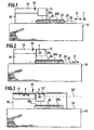
Ein in Fig. 1 dargestelltes Ausführungsbeispiel einer erfindungsgemäßen Vorrichtung zum Belichten von Substratmaterialien umfaßt eine Belichtungseinrichtung 10, welche einen Optikkopf 12 und eine diesem zugeordnete Belichtungssteuerung 14 umfaßt.An exemplary embodiment of a device according to the invention for exposing substrate materials shown in FIG. 1 comprises an
Die Belichtungseinrichtung 10 ist dabei beispielsweise mittels eines Brückenkörpers 16 an einem Fundamentkörper 18 abgestützt.The
Der Brückenkörper 16 übergreift dabei einen Bewegungsbereich 20, in welchem ein Trägerschlitten 22 relativ zum Fundamentkörper 18 bewegbar ist, wobei der Trägerschlitten 22 auf einer Führungsebene 24 des Fundamentkörpers 18 gleitend, beispielsweise durch Luftpolster geführt ist, wie dies in der deutschen Patentanmeldung DE 10212344 A1 beschrieben ist.The
Auf den Trägerschlitten 22 ist ferner noch ein Substratträger 26 angeordnet, auf welchem beispielsweise zwei zur Belichtung vorgesehene Substratkörper 28a, b gehalten sind, die durch die Belichtungseinrichtung 10 belichtet werden sollen.Furthermore, a
Hierzu ist der Trägerschlitten 22 durch in Fig. 1 nicht dargestellte Antriebseinheiten für den Trägerschlitten 22 beispielsweise sowohl in einer X-Richtung als Hauptrichtung als auch in einer senkrecht zu dieser verlaufenden Y-Richtung als Nebenrichtung, die beide parallel zur Führungsebene 24 verlaufen, innerhalb des Bewegungsbereichs 20 bewegbar und exakt relativ zur Belichtungseinrichtung 10, insbesondere zum Optikkopf 12 derselben positionierbar.For this purpose, the
Der Bewegungsbereich 20 für den Trägerschlitten 22 ist dabei so dimensioniert, daß die Substratkörper 28 auf ihrer gesamten Substratoberfläche 30 belichtet werden können.The
Es ist aber auch denkbar, den Trägerschlitten 22' in X-Richtung zu bewegen und den Optikkopf 12' relativ zum Brückenkörper 16 in Y-Richtung zu bewegen, wie in Fig. 2 dargestellt.However, it is also conceivable to move the carrier carriage 22 'in the X direction and to move the optical head 12' relative to the
Alternativ dazu ist es auch denkbar, den Substratträger 26 stationär anzuordnen und relativ zum Substratträger 26 den Optikkopf 12" relativ zum Brückenkörper 16" in X- und Y-Richtung in einem Bewegungsbereich 20" zu bewegen, um ebenfalls die gesamte Oberfläche 30 des jeweiligen Substrats zu belichten, wie in Fig. 3 dargestellt.Alternatively, it is also conceivable to arrange the
Ein derartiger Substratkörper 28 ist beispielsweise - wie in Fig. 4 dargestellt - ein sogenannter Wafer, wie er in der Halbleitertechnik verwendet wird. Die Belichtung des Wafers erfolgt dazu, um auf diesem definierte Strukturen 32 zu erzeugen, wobei eine oder mehrere derartiger Strukturen 32 dann eine Baugruppe 34, beispielsweise ein elektrisches, ein elektronisches oder ein optisches Bauelement, ergeben.Such a
Dabei erstrecken sich die definierten Strukturen 32 nicht über die gesamte Oberfläche 30 des Substratkörpers 28, sondern es sind in der Regel eine Vielzahl von Baugruppen 34 auf einem derartigen Substratkörper 28 herstellbar, wobei insbesondere alle Baugruppen 34 durch dieselben Strukturen 32 aufgebaut sind.In this case, the defined
Zum Herstellen der Baugruppen 34 werden diese vorzugsweise in Reihen 36 auf dem Substratkörper 28 angeordnet, wobei die Reihen 36 sich vorzugsweise parallel zur Hauptrichtung X und senkrecht zur Nebenrichtung Y erstrecken.For producing the
Zum Herstellen der definierten Strukturen 32 für die Baugruppen 34 ist es nun erforderlich, jede der Baugruppen 34 durch Belichten mit der Belichtungseinrichtung 10 mit derselben Struktur 32 zu versehen.In order to produce the defined
Hierzu wird vorzugsweise eine Relativbewegung zwischen der Belichtungseinrichtung 10 und dem Substratträger 26 längs der Hauptrichtung X erzeugt, so, daß vorzugsweise sämtliche Baugruppen 34 einer der Reihen 36 in einem Zug durch die Relativbewegung in der Hauptrichtung X überfahren und dabei belichtet werden und nachfolgend nach einem Versatz in der Nebenrichtung Y ebenfalls wieder ein Überfahren und Belichten sämtlicher Baugruppen 34 einer der Reihen 36 erfolgt.For this purpose, preferably, a relative movement between the
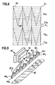
Das Herstellen der Strukturen erfolgt, wie in Fig. 5 dargestellt, durch Belichten der Oberfläche 30 des Substratkörpers innerhalb des Bereichs der jeweiligen Baugruppen 34 in einem Raster 38, bestehend aus einzelnen Rasterpunkten RP, die einen Rasterabstand RX und RY voneinander aufweisen, wobei dieser Rasterabstand RX, RY beispielsweise in der Größenordnung von 50 Nanometern liegt.Fabrication of the structures is accomplished, as shown in FIG. 5, by exposing the
Jeder Rasterpunkt RP stellt ein Zentrum eines Pixelflecks PF dar, welcher ausgehend von dem Zentrum RP eine Pixelausdehnung PA aufweist, die ein Vielfaches des Rasterabstands RX, RY, beispielsweise bis zum ungefähr Fünffachen derselben beträgt.Each raster point RP represents a center of a pixel patch PF which, starting from the center RP, has a pixel extent PA which is a multiple of the raster spacing RX, RY, for example up to approximately five times the same.
Werden somit die Pixelflecken PF in dem Raster 38 mit den Rasterpunkten RP als Zentrum nebeneinanderliegender Pixelflecken PF belichtet, so lassen sich zusammenhängende Strukturen 32 erzeugen, bei welchen nebeneinanderliegende Pixelflecken PF mehrfach, beispielsweise fünffach, überlappen, so daß sich relativ geradlinig verlaufende Strukturkanten 40 der belichteten Struktur 32 aus aufeinanderfolgenden Pixelflecken PF bei längs aufeinanderfolgender Rasterpunkte RP sitzenden Pixelflecken PF erzeugen lassen.Thus, if the pixel spots PF are exposed in the
Um zum Positionieren der einzelnen Pixelflecken PF in dem Raster 38 die Relativbewegung zwischen dem Substratträger 26 und dem Optikkopf 12 in geeigneter Weise ausnützen zu können, werden die Rasterpunkte RP in Zeilen Z, beispielsweise in Fig. 5 den Zeilen Z1 bis Z10 angeordnet, die parallel zur Hauptrichtung X und senkrecht zur Nebenrichtung Y und somit auch parallel zu den Reihen 36 verlaufen.In order to be able to use the relative movement between the
Prinzipiell wäre es denkbar, die Belichtungseinrichtung 10 so auszubilden, daß zur Belichtung in jeder der Zeilen Z jederzeit ein eigener Belichtungsstrahl 42 zur Verfügung steht, so daß bei der Relativbewegung zwischen der Belichtungseinrichtung 10 und dem Substratträger 26 in der Hauptrichtung X beispielsweise in allen Zeilen Z zu einem bestimmten Zeitpunkt ein Pixelfleck PF erzeugt werden könnte.In principle, it would be conceivable to design the
Bei einer besonders günstigen Lösung ist, wie in Fig. 6 dargestellt, vorgesehen, daß der zur Erzeugung eines Pixelflecks PF vorgesehener Belichtungsstrahl 42 in der Nebenrichtung Y so über das Raster 38 bewegbar ist, daß der Pixelfleck PF mit seinem Zentrum beispielsweise auf jeder von 10 Zeilen Z1 bis Z10 positionierbar ist.In a particularly favorable solution, it is provided, as shown in Fig. 6, that the provided for generating a pixel spot
Hierzu ist zur Erzeugung des Belichtungsstrahls 42 beispielsweise eine Lichtquelle 44, beispielsweise in Form einer Laserdiode, vorgesehen, deren Lichtstrahl durch eine Ablenkeinheit 46 kombiniert mit einer Mikroskopoptik 48 derart ablenkbar ist, daß der Belichtungsstrahl 42 einen Pixelfleck PF auf der Oberfläche 30 des Substrats erzeugen kann, dessen Zentrum auf jeder der Zeilen Z1 bis Zeile Z10 in dem jeweiligen Rasterpunkt RP positionierbar ist (Fig. 7).For this purpose, for generating the
Die von der Lichtquelle 44 mit dem Belichtungsstrahl 42 erfassbaren Zeilen Z1 bis Z10 bilden somit einen Zeilenstreifen ZS der sich, wie in Fig. 6 dargestellt, in der Hauptrichtung X erstreckt.The lines Z1 to Z10 detectable by the
Wie in Fig. 8 mit in Hauptrichtung X vergrößert gezeichnetem Rasterabstand RX im Verhältnis zum Rasterabstand Y dargestellt, wird nun zum Erfassen der Zeilen Z1 bis Z10 eines Zeilenstreifens der Belichtungsstrahl 42 durch die Ablenkeinheit 46 periodisch abgelenkt und schwenkt daher mit festgelegter Zeitkonstante von der Zeile Z1 zur Zeile Z10 und wieder zu dieser zurück, so daß dann, wenn ein Pixelfleck PF mit einem Zentrum auf einem der Zeilen Z1 bis Z10 erzeugt werden soll, zu dem Zeitpunkt eine Belichtung erfolgen muß, zu dem bei der periodischen Schwenkbewegung des Belichtungsstrahls 42 der Belichtungsstrahl 42 mit seinem Zentrum genau auf der ausgewählten Zeile Z des Zeilenstreifens liegt.As shown in Fig. 8 with magnified in the main direction X drawn grid spacing RX in relation to the grid spacing Y, is now for detecting the lines Z1 to Z10 of a line strip of the
Dies führt zwar zu einer geringfügigen Verzerrung des Rasters 38 dahingehend, daß die Rasterpunkte RP in der Zeile Z10 gegenüber den Rasterpunkten RP der Zeile Z1 in Hauptrichtung X um einen Rasterabstand RX/2 verschoben ist, diese Verzerrung ist jedoch aufgrund der Ausdehnung der Pixelflecken PF relativ zu den Rasterabständen RX und RY vernachlässigbar.Although this leads to a slight distortion of the
Um mit der erfindungsgemäßen Belichtungseinrichtung 10, insbesondere dem Optikkopf 12 nicht nur einen Zeilenstreifen ZS1 sondern beispielsweise N Zeilenstreifen ZS (Fig. 9) belichten zu können, sind eine Vielzahl von Lichtquellen 441 bis 44N mit entsprechenden Ablenkeinheiten 461 bis 46N und Mikroskopoptiken 481 bis 48N in dem Optikkopf 12 vorgesehen, die alle bei einer Relativbewegung zwischen dem Optikkopf 12 und dem Substratträger 26 in der Hauptrichtung X gleichzeitig betreibbar sind.To be able to expose not only a line strip ZS1 but for example N line strips ZS (FIG. 9) with the
Um mit der erfindungsgemäßen Belichtungseinrichtung 10 möglichst viele Zeilen Z bei einer einzigen Bewegung in der Hauptrichtung X belichten zu können, wird eine große Zahl N von Lichtquellen 44 mit Ablenkeinheiten 46 und Mikroskopoptiken 48 eingesetzt. Sinnvoll sind dabei Zahlen von einigen hundert Lichtquellen 44, beispielsweise 504 Lichtquellen, die damit in der Lage sind, bei einer Bewegung in der Hauptrichtung X im Bereich von 5040 Zeilen Z eine Belichtung durch einen Pixelfleck PF vorzunehmen.In order to be able to expose as many lines Z as possible with the
Zusätzlich sind, um definierte Strukturen 32, insbesondere mit gut abgesetzten Strukturkanten 40 erzeugen zu können, für einen Pixelfleck PF mehrere Graustufen vorgesehen, beispielsweise mehr als 10 Graustufen, vorzugsweise 32 Graustufen pro Pixelfleck PF.In addition, in order to be able to generate defined
Dies führt bei einer Relativgeschwindigkeit zwischen der Belichtungseinrichtung 10 und dem Substratträger 26 in der Größenordnung von einem Meter pro Sekunde zu Datenmengen und Datenraten, die bei Rasterabständen RX, RY im Bereich um 50 Nanometer in technologische Grenzbereiche der verfügbaren Bauteile führen.At a relative speed between the
Aus diesem Grund ist es nicht möglich, die zum Schreiben der Zeilen Z innerhalb der Zeilenstreifen ZS1 bis ZSN erforderlichen Daten aus dem Speicher eines übergeordneten Rechners, beispielsweise eines Host-Rechners während des Belichtungsvorgangs bei einer Bewegung in der Hauptrichtung X auszulesen, sondern es ist erforderlich, eine Steuerung 50 für die gleichzeitige Ansteuerung der Lichtquellen 44 vorzusehen, welcher ein eigener Steuerungsspeicher 52 zugeordnet ist, der es der Steuerung 50 erlaubt, die Datensätze für die Zeilensätze ZS1 bis ZSN mit möglichst großer Datenrate auszulesen.For this reason, it is not possible to read the data required for writing the lines Z within the line strips ZS1 to ZSN from the memory of a higher-level computer, for example a host computer, during the exposure process when moving in the main direction X, but it is necessary to provide a
Da eine typische Baugruppe 34, die auf einem Substrat in erfindungsgemäßer Weise durch Belichtung mit einer definierten Struktur 32 versehen werden soll und üblicherweise Dimensionen im Bereich bis zu einigen Zentimetern aufweist, ist auch die mit beispielsweise mehreren hundert Lichtquellen 44 versehene Belichtungseinrichtung 10 nicht in der Lage, im Bereich aller für die Herstellung der Struktur 32 der Baugruppe 34 erforderlichen Zeilen Z eine Belichtung vorzunehmen.As a
Vielmehr ist es erforderlich, wie in Fig. 10 dargestellt, mit der erfindungsgemäßen Belichtungseinrichtung 10 mehrfach in der Hauptrichtung X, jedoch in der Nebenrichtung Y versetzt die Baugruppe 34 zu überfahren und dabei zu belichten.Rather, it is necessary, as shown in Fig. 10, with the
Die durch einmaliges Überfahren der Baugruppe 34 in der Hauptrichtung X mit den Lichtquellen 441 bis 44N belichtbaren Zeilen, umfaßt durch die Zeilensätze ZS1 bis ZSN, werden dabei als Makrozeile MZ bezeichnet, so daß zum Belichten sämtlicher für die Struktur 32 der Baugruppe 34 erforderlichen Zeilen, wie in Fig. 7 und 8 dargestellt, insgesamt ein Belichten der Baugruppe 34 im Bereich von M nebeneinanderliegenden Makrozeilen MZ erforderlich ist.The to 44 N exposable in the main direction X with the
Da die die Lichtquellen 44 ansteuernde Steuerung 50 schnellen Zugriff auf den Steuerungsspeicher 52 haben muß, wäre es, wenn insgesamt M Makrozeilen. MZ belichtet werden müssen, erforderlich, in dem Steuerungsspeicher 52 die Datensätze für alle M Makrozeilen MZ der Baugruppe 34 zu speichern.Since the
Dies hätte zur Folge, daß der Steuerungsspeicher 52 sehr groß ausgelegt werden müßte und somit kostenintensiv wäre.This would mean that the
Aus diesem Grund ist vorgesehen, daß der Steuerungsspeicher 52 so ausgebildet ist, daß aus diesem einerseits Datensätze für das Belichten der Zeilen Z durch die Steuerung für die Lichtquellen 44 auslesbar sind, gleichzeitig aber auch Datensätze aus einem Hauptspeicher 54 eines übergeordneten Rechners, beispielsweise des Host-Rechners, einlesbar sind. Damit ist es möglich, während des Belichtens im Bereich einer Makrozeile MZ und somit des Auslesens der Datensätze für dieses Belichten gleichzeitig Datensätze für eine weitere Makrozeile MZ einzulesen.For this reason, it is provided that the
Im Rahmen der erfindungsgemäßen Lösung ist es ferner vorteilhaft, wie in Fig. 11 dargestellt, eine Belichtung im Bereich einer der Makrozeilen MZ nicht nur im Bereich einer einzigen Baugruppe 34 vorzunehmen, sondern im Bereich mehrerer Baugruppen 34, wobei diese Baugruppen 34 längs eines Belichtungswegs W angeordnet sind. Die Größe des Steuerungsspeichers 52 hängt dabei davon ab, wie groß die Zeit ist, die für einen Belichtungsweg W benötigt wird, und wie schnell die Datensätze aus dem Hauptspeicher 54 in dem Steuerungsspeicher 52 abgespeichert werden können.In the context of the solution according to the invention, it is also advantageous, as shown in FIG. 11, to perform an exposure in the region of one of the macro-lines MZ not only in the region of a
Im einfachsten Fall wird beispielsweise ein erster Belichtungsweg W1 für eine Belichtung im Bereich der ersten Makrozeile MZ1, wie in Fig. 11 dargestellt, so gelegt, daß er die Baugruppen 34 erfaßt, die längs einer Reihe 36 angeordnet sind, wobei die Baugruppe 34 die Baugruppen auf einem Substratkörper 28 sind.In the simplest case, for example, a first exposure path W1 for an exposure in the region of the first macro-line MZ 1 , as shown in Fig. 11, placed so that it detects the
Ausgehend von der Zielvorstellung, die M Makrozeilen MZ möglichst ohne Unterbrechung der Bewegung in der Hauptrichtung X zu schreiben, ist der Steuerungsspeicher 52 lediglich so groß zu wählen, daß er etwas mehr als die Hälfte der Makrozeilen MZ speichern kann, wenn der Transfer der Datensätze von dem Hauptspeicher 54 in den Steuerungsspeicher 52 und das Abspeichern derselben so schnell erfolgen kann, daß es während des Durchlaufens des Belichtungswegs W1 von seinem Anfang W1A zu seinem Ende W1E, der alle Baugruppen 34 längs der Reihe 36x erfaßt, möglich ist, ungefähr die Hälfte der Datensätze einer weiteren, noch nicht im Steuerungsspeicher 52 abgelegten Makrozeile MZ zu speichern.Starting from the goal of writing the M macro-lines MZ without interruption of the movement in the main direction X, the
Es ist nämlich dann möglich, zunächst alle im Steuerungsspeicher 52 gespeicherten Makrozeilen durch Fahren entsprechender Belichtungswege W abzuarbeiten, wobei durch das stets erfolgende Abspeichern weiterer Makrozeilen MZ aus dem Hauptspeicher 54 stets ungefähr die Hälfte der bereits abgearbeiteten Makrozeilen MZ neu gespeichert wird, so daß insgesamt eine Größe des Steuerungsspeichers 52 ausreicht, die zwischen 50 und 60% der Datensätze der M Makrozeilen der Baugruppe 34 speichern kann.Namely, it is then possible to first process all of the macro lines stored in the
Bei den gegebenen Voraussetzungen läßt sich jedoch die Größe des Steuerungsspeichers 52 noch weiter reduzieren, wenn der Belichtungsweg W verlängert wird.Under the given conditions, however, the size of the
Wird beispielsweise der in Fig.11 dargestellte Belichtungsweg W'1 gefahren, welcher von seinem Anfang W'IA bis zu seinem Ende W'1E die Baugruppen 34 erfaßt, die längs zweier Reihen 36Y und 36Y+1 angeordnet sind, so ist bei derselben Geschwindigkeit in der Hauptrichtung X und derselben Datentransferrate vom Hauptspeicher 54 in den Steuerungsspeicher 52, von welcher vorstehend ausgegangen wurde, es bereits möglich, während des Durchlaufens des Belichtungsweges W'1 die Datensätze einer gesamten weiteren Makrozeile MZ im Steuerungsspeicher 52 abzulegen.For example, if the exposure path W'1 shown in Fig. 11 is used, which detects from its beginning W'IA to its end W'1E the
Das heißt, es ist pro Belichtungsweg W', im Verlauf von welchem nur Datensätze einer Makrozeile MZ, beispielsweise der Makrozeile M1 ausgelesen werden, möglich sämtliche Datensätze einer weiteren Makrozeile, beispielsweise der Makrozeile MZ2, vom Hauptspeicher 54 im Steuerungsspeicher 52 abzuspeichern.That is, it is per exposure path W ', in the course of which only data sets of a macro line MZ, for example, the macro line M1 are read, all data sets of another macro line, such as the macro line MZ 2 , from the
In diesem Fall muß der Steuerungsspeicher 52 lediglich so groß gewählt werden, daß er in der Lage ist, die Datensätze zweier Makrozeilen MZ zu speichern, nämlich die Datensätze, die im Verlauf des Belichtungsweges W' für die jeweilige Makrozeile MZ ausgelesen werden und die Datensätze, die für die als nächstes zu belichtende Makrozeile MZ aus dem Hauptspeicher 54 in den Steuerungsspeicher 52 eingelesen und abgespeichert werden.In this case, the
Die Zeit, die für einen Belichtungsweg benötigt wird, läßt sich jedoch aber auch noch weiter dadurch vergrößern, daß auf dem Substratträger 26 nicht nur ein Substratkörper 28, sondern zwei Substratkörper 28a, b angeordnet werden, wobei die herzustellenden definierten Strukturen 32 der Baugruppen 34 identisch sind (Fig. 12).However, the time required for an exposure path can be increased even further by disposing on the
Ferner sind die Baugruppen 34 auf beiden Substratkörpern 28a, b so anzuordnen, daß sie jeweils in einer gemeinsamen Reihe 36 liegen.Furthermore, the
In diesem Fall läßt sich die Zeit, die für das Durchlaufen des jeweiligen Belichtungswegs W, in diesem Fall des Belichtungswegs W1" benötigt wird, dadurch vergrößern, daß der Belichtungsweg W1" die Baugruppen 34 erfaßt, die längs der Reihe 36 auf beiden Substratkörpern 28a, b angeordnet sind.In this case, the time required to pass through the respective exposure path W, in this case the exposure path W1 ", can be increased by the exposure path W1" detecting the
Die Zeit für das Durchlaufen des Belichtungswegs W1" von seinem Anfang W1"A bis zu seinem Ende W1"E ist zwangsläufig größer als die Zeit für das Durchlaufen des Belichtungswegs W1, dargestellt in Fig. 12 und liegt vorzugsweise in der Größenordnung der Zeit für das Durchlaufen des Belichtungswegs W1", dargestellt in Fig. 12, allerdings mit dem Vorteil, daß zum Durchlaufen des Belichtungswegs W1" lediglich eine geradlinige Bewegung in der Hauptrichtung X erforderlich ist und keine Bewegung in der Nebenrichtung Y, so daß beispielsweise für die gegenläufige Bewegung in der Hauptrichtung X bereits das Schreiben einer weiteren Makrozeile MZ vorgesehen werden kann.The time for traversing the exposure path W1 "from its beginning W1" A to its end W1 "E is necessarily larger than the time for traversing the exposure path W1 shown in Fig. 12, and is preferably on the order of the time for the Passing through the exposure path W1 ", shown in Fig. 12, but with the advantage that for passing through the exposure path W1" only a rectilinear movement in the main direction X is required and no movement in the secondary direction Y, so that, for example, for the opposite movement in the main direction X already writing a further macro-line MZ can be provided.
Erfolgt jedoch die Bewegung in der Hauptrichtung X sehr schnell oder ist die Datentransferrate für das Transferieren und Abspeichern der Datensätze einer Makrozeile MZ vom Hauptspeicher 54 in den Steuerungsspeicher 52 gering, so läßt sich eine weitere Vergrößerung der Zeit für das Durchlaufen des Belichtungswegs W dann erreichen, wenn, wie in Fig. 12, bei den Baugruppen 34 zweier Substratkörpern 28a, b eine Belichtung im Bereich einer Makrozeile MZ längs des Belichtungswegs W1"' erfolgt, der die Baugruppen 34 von zwei, beispielsweise nebeneinanderliegenden Reihen 36W und 36W+1 erfaßt und somit mindestens doppelt so lang wie der Belichtungsweg W" ist.However, if the movement in the main direction X is very fast, or if the data transfer rate for transferring and storing the data sets of a macro line MZ from the
Ist die Bewegung in der Hauptrichtung X sehr schnell und die Datenraten für den Transfer der Datensätze von dem Hauptspeicher 54 in den Steuerungsspeicher sehr gering, so läßt sich im Extremfall, wie in Fig. 13 dargestellt, ein Belichtungsweg W1"" wählen, welcher vorsieht, daß dieselbe Makrozeile MZ, beispielsweise die Makrozeile MZ1 auf allen Baugruppen 34 von allen Substratkörpern 28a, b des Substratträgers 26 von dem Belichtungsweg W1"" erfaßt wird.If the movement in the main direction X is very fast and the data rates for the transfer of the data sets from the
Bei beispielsweise zwei auf dem Substratträger 26 vorhandenen Substratkörpern 28a, b ist dies die maximal mögliche Länge eines möglichen Belichtungswegs W, der somit auch die maximal mögliche Zeit zur Verfügung stellt, um die Datensätze einer weiteren Makrozeile MZ von dem Hauptspeicher 54 in den Steuerungsspeicher 52 zu transferieren und dort abzuspeichern.In the case of, for example, two
Die Verwendung einer Vielzahl, beispielsweise mehrerer hundert von Lichtquellen 44 und die gleichzeitige Ansteuerung derselben mit der Steuerung 50 führt ebenfalls an die Grenze der für eine derartige Steuerung 50 und einen derartigen Steuerungsspeicher 52 einsetzbaren Bauteile.The use of a plurality, for example, several hundred of
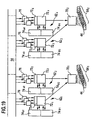
Aus diesem Grund wird die Gesamtheit der Lichtquellen 44 in Lichtquellengruppen 64 aufgeteilt, wobei jede Lichtquellengruppe 64 ungefähr 20 bis 40 Lichtquellen, vorzugsweise 25 bis 35 Lichtquellen umfaßt. Im dargestellten Ausführungsbeispiel umfaßt jede Lichtquellengruppe 28 Lichtquellen 44 (Fig. 14).For this reason, the totality of the
Bei einer derartigen Struktur der Lichtquellengruppen 64 ist die Steuerung 50 aufgeteilt in einzelne Gruppensteuerungen 70, wobei jede Gruppensteuerung 70 unabhängig von der anderen Gruppensteuerung arbeitet, um die dieser zugeordnete Lichtquellengruppe 64, vorzugsweise Treiber der einzelnen Lichtquellen 44 der Lichtquellengruppe 64, gleichzeitig anzusteuern.With such a structure of the
Ferner ist auch der Steuerungsspeicher 52 aufgeteilt. Vorzugsweise ist der Steuerungsspeicher 52 gebildet aus einer Vielzahl von Steuerungsspeichereinheiten 62, wobei jede Steuerungsspeichereinheit 62 einen Steuerungsmodul 72 aufweist, welcher mit mehreren Steuerungsspeichermodulen 74, vorzugsweise ausgebildet als RAM, zusammenwirkt. Beispielsweise wirkt jeder Steuerungsmodul 72 mit zwei Steuerungsspeichermodulen 74a, b oder einer noch größeren Zahl von Steuerungsspeichermodulen 74 zusammen (Fig. 14).Furthermore, the
Der Steuerungsmodul 72 selbst ist vorzugsweise als sogenannter RAM FPGA ausgebildet und dient dazu, einerseits aus dem jeweiligen Steuerungsspeichermodul 74 Datensätze auszulesen und gleichzeitig aber auch Datensätze in diesen einzulesen.The control module 72 itself is preferably designed as a so-called RAM FPGA and serves, on the one hand, to read out data records from the respective
Der Transfer der Datensätze aus dem Hauptspeicher 54 erfolgt durch sogenannte Schnittstellenmodule 76, insbesondere USB's, welche zwischen dem Hauptspeicher 54 und dem jeweiligen Steuerungsmodul 72 zum parallelen Übertragen der Datensätze aus dem Hauptspeicher 54 vorgesehen sind, wobei der Steuerungsmodul 72 dann seinerseits wiederum diese Datensätze in den Steuerungsspeichermodulen 74 abspeichert.The transfer of the data records from the
Jeder der unabhängig voneinander arbeitenden Gruppensteuerungen 70 ist vorzugsweise nicht nur einer Steuerungsspeichereinheit 62 zugeordnet, sondern es sind mehrere Steuerungsspeichereinheiten 62 pro Gruppensteuerung 70 vorgesehen. Im in Fig. 14 dargestellten Fall sind jeder der Gruppensteuerungen 701 und 702 jeweils zwei Steuerungsspeichereinheiten 621und 622 bzw. 623 und 624 zugeordnet.Each of the independently operating group controllers 70 is preferably not associated with only one
Jede der Lichtquellengruppen 64 ist somit in der Lage, in einem Teil der Vielzahl V von Zeilen Z einer Makrozeile MZ eine Belichtung durchzuführen.Each of the
Da - wie bereits dargelegt - jeder Lichtquelle 44 vorzugsweise ein Zeilenstreifen ZS umfassend mehrere Zeilen Z zugeordnet ist, entspricht die Zahl T der Zeilen Z, in welcher mittels einer Lichtquellengruppe 64 eine Belichtung durchführbar ist, der Zahl der Zeilen Z pro Zeilenstreifen ZS multipliziert mit der Zahl Q der Lichtquellen 44 pro Lichtquellengruppe 64.Since, as already explained, each
Die Zahl T von Zeilen Z, die somit einer Lichtquellengruppe 64 zugeordnet ist, bildet insgesamt einen sich in der Hauptrichtung X erstreckenden Gruppenstreifen GS.The number T of lines Z, which is thus assigned to a
So lange die für die definierte Struktur vorgesehenen Strukturzeilen eindeutig den Zeilen Z zugeordnet bleiben, so lange können die Gruppenstreifen GS so angeordnet werden, daß bei aneinander angrenzenden Gruppenstreifen, beispielsweise den Gruppenstreifen GS4 und GS5 in Fig. 15, das die erste Zeile ZE5 des auf den Gruppenstreifen GS4 folgenden Gruppenstreifens GS5 im Rasterabstand RY von der letzten Zeile ZL4 des Gruppenstreifens GS4 angeordnet ist.As long as the structure lines provided for the defined structure remain unambiguously associated with the rows Z, the group strips GS can be arranged so that, in the case of adjoining group strips, for example the group strips GS 4 and GS 5 in FIG. 15, the first line ZE 5 of the following on the group strip GS 4 group strip GS 5 in the grid spacing RY from the last line ZL 4 of the group strip GS 4 is arranged.
Bei der Relativpositionierung der Belichtungseinrichtung 10, insbesondere des Optikkopfes 12 zu den Substraten 28a, b auf dem Substratträger 26 ist jedoch ein Positionierfehler in der Nebenrichtung Y möglich, der insbesondere dann korrigiert werden muß, wenn mehrere definierte Strukturen 32 übereinander gelegt werden, die relativ zueinander exakt positioniert sein sollen.In the relative positioning of the
Ein derartiger Positionierfehler in der Nebenrichtung Y kann zwar durch den Antrieb für die Positionierung des Trägerschlittens 32 ausgeglichen werden.Although such a positioning error in the secondary direction Y can be compensated by the drive for the positioning of the
Eine besonders vorteilhafte Ausführungsform sieht jedoch vor, daß mit dem Trägerschlitten 22 eine Grobpositionierung in der Nebenrichtung Y erfolgt, während eine eine Parallelverschiebung in Y-Richtung umfassende Feinpositionierung der Strukturen 32 relativ zueinander durch unterschiedliche Zuordnung der Datensätze von die Struktur 32 definierenden Strukturzeilen SZ zu den einzelnen Zeilen Z erfolgt, in welchen belichtbar ist.A particularly advantageous embodiment, however, provides that with the
Das heißt, daß die Gesamtzahl G von Zeilen Z, in welchen ein Belichten des Substrats 28 im Bereich der jeweiligen Baugruppe 34 mit der Belichtungseinrichtung 10 möglich ist, größer ist als die Gesamtzahl S von Strukturzeilen SZ, im Bereich von welchen eine Belichtung erforderlich ist, um die definierte Struktur 32 zu erzeugen.That is, the total number G of lines Z, in which exposure of the
Das heißt, daß eine Zuordnung der Strukturzeilen SZ zu den Zeilen Z, in welchen eine Belichtung des Substratkörpers 28 möglich ist, variabel gehalten werden kann.That is, an association of the structure lines SZ to the lines Z in which exposure of the
Beispielsweise ist es denkbar, die erste Strukturzeile SZ1 der ersten Zeile Z1 der Makrozeile MZ, in welcher eine Belichtung durchzuführen ist, zuzuordnen, wie in Fig. 16 durch die durchgezogen gezeichneten Pfeile dargestellt ist. Die Zuordnung der nächstfolgenden Strukturzeilen SZ2 und folgende erfolgt dabei zu den nächstfolgenden Zeilen Z2 und folgende.For example, it is conceivable to associate the first structure line SZ 1 of the first line Z 1 of the macro line MZ in which an exposure is to be performed, as shown in FIG. 16 by the arrows drawn in solid lines. The assignment of the next structure lines SZ 2 and following takes place to the next following lines Z 2 and following.
Es ist aber auch denkbar, mittels der Steuerung 50 die erste Strukturzeile SZ1 beispielsweise der elften Zeile Z11 der Makrozeile MZ, in welcher eine Belichtung durchführbar ist, zuzuordnen, wie in Fig. 16 durch gestrichelte Pfeile dargestellt, oder, wie in Fig. 14 durch gepunktete Pfeile dargestellt, die erste Strukturzeile SZ1 der 75. Zeile Z75 der Makrozeile MZ, in welcher eine Belichtung durchführbar ist, zuzuordnen.However, it is also conceivable, by means of the
Die variable Zuordnung der Strukturzeilen SZ zu tatsächlich zu schreibenden Zeilen Z durch die Steuerung hat - wenn lediglich die Makrozeilen betrachtet werden - die Folge, daß die Zahl der dem Steuerungsspeicher 52 zu speichernden Datensätze größer wird, da für jede zwischen der ersten und letzten Makrozeile MZ1 und MZM liegende Makrozeile MZ nicht nur die Datensätze für die Gesamtzahl V von tatsächlich zu schreibenden Zeilen Z der Makrozeile gespeichert werden müssen, sondern dazu noch die beiderseits der jeweiligen Makrozeile MZ angrenzende Zahl U von Zeilen, wobei die Zahl U von Zeilen der halben maximal möglichen Verschiebung der Zuordnung von Strukturzeilen SZ und Zeilen entspricht, die von der Steuerung 50 noch beim Ansteuern der Lichtquellen 44 doch geändert werden kann.The variable assignment of the structure lines SZ to actually write lines Z by the controller has - when only the macro lines are considered - the consequence that the number of the
Erfolgt eine derartige Veränderung der Zuordnung der Strukturzeilen SZ relativ zu den Zeilen Z, in welche eine Belichtung tatsächlich durchführbar ist, so hat dies zur Folge, daß beim Vorsehen von Lichtquellengruppen 64 und unabhängig voneinander arbeitenden, diesen Lichtquellengruppen 64 zugeordneten Gruppensteuerungen 70 die Möglichkeit der Veränderung der Zuordnung bei jedem der Gruppenstreifen GS, der von einer Lichtquellengruppe 64 erzeugt wird, zu berücksichtigen ist. Das heißt, daß jeder der Gruppensteuerungen 70, wie in Fig. 17 dargestellt, nicht nur von der Gesamtzahl der Strukturzeilen SZ eine Teilmenge von Datensätzen zur Verfügung gestellt werden darf, die genau einer Zahl T von Zeilen Z entspricht, in denen tatsächlich belichtet werden kann, sondern eine Teilmenge von Datensätzen der Gesamtzahl von Strukturzeilen zur Verfügung gestellt werden muß, die gegenüber der Zahl der Zeilen Z eines Gruppenstreifens GS beiderseits des Gruppenstreifens GS um eine Zahl U vergrößert ist.If such a change in the assignment of the structure lines SZ relative to the lines Z, in which an exposure is actually feasible, this means that the provision of
So sind beispielsweise zum Belichten innerhalb des Gruppenstreifens GS4 nicht nur die Datensätze der Strukturzeilen SZE1 bis SZL1 zur Verfügung zu stellen, die zum Belichten innerhalb eines Bereichs von T möglichen Zeilen Z des Gruppenstreifens GS4 erforderlich sind, sondern Datensätze von der Strukturzeile SZ(E-U)4 bis zur Strukturzeile SZ(L+U)4, so daß mit der Gruppensteuerung 70 noch die Möglichkeit besteht, innerhalb der Strukturzeilen SZ(E-U)4 und SZ(L-U)4 zu belichten, die in diesem Fall den Zeilen ZE1 bis ZL4 zugeordnet würden oder die Zuordnung soweit zu verschieben, daß im Bereich der Strukturzeilen SZ(E+U)4 und SZ (L+U)4 eine Belichtung erfolgt, die in diesem Fall den Zeilen ZE4 bis ZL4 des Gruppenstreifen GS4 zugeordnet würden.Thus, for example, for exposure within the group strip GS 4, it is not only necessary to provide the data sets of the structure lines SZE1 to SZL1 which are required for exposure within a range of T possible lines Z of the group strip GS 4 , but data records from the structure line SZ (EU ) 4 to the structure line SZ (L + U) 4 , so that with the group control 70 still has the possibility to expose within the structure lines SZ (EU) 4 and SZ (LU) 4 , in this case the rows Z E1 to Z L4 would be assigned or the assignment to move so far that in the area of the structure lines SZ (E + U) 4 and SZ (L + U) 4 takes place an exposure, in this case the lines Z E4 to Z L4 of the group strip GS 4th would be assigned.
Damit wird die Datenmenge, die für jede der Gruppensteuerungen 70 in den dieser zugeordneten Steuerungsspeichermodulen 74 zu speichern ist, insgesamt vergrößert.Thus, the amount of data to be stored for each of the group controllers 70 in the
Ferner ist in Fig. 17 dargestellt, daß sich die der den Gruppenstreifen GS4 erzeugenden Lichtquellengruppen 64 zur Verfügung gestellte Teilmenge von Strukturzeilen SZ(E-U)4 bis SZ(L+U)4 und die der den Gruppenstreifen GS5 erzeugenden Lichtquellengruppe 64 zur Verfügung gestellte Teilmenge von Strukturzeilen SZ(E-U)5 bis SZ(L+U)5 in einem Überlappungsbereich UB überlappen, und somit in diesen für jede der Lichtquellengruppen 64 dieselben Strukturzeilen SZ(E-U)5 bis SZ(L+U)4 zur Verfügung gestellt werden müssen.Further, in Fig. 17, that the of the group strips GS 4-generating
Bei einem zweiten Ausführungsbeispiel einer erfindungsgemäßen Vorrichtung - dargestellt in Fig. 18 - zum Belichten von Substraten, insbesondere entsprechend einem der vorstehend beschriebenen Verfahren, sind, wie in Fig. 18 dargestellt, insgesamt vier Vorrichtungen A1, A2, B1, B2 zum Belichten von Substratkörpern 28 vorgesehen, wobei aus Gründen der Vereinfachung lediglich deren Trägerschlitten 22A1, 22A2, 22B1, 22B2 dargestellt sind und die Belichtungseinrichtung 10 der einzelnen Vorrichtungen nicht dargestellt ist.In a second embodiment of a device according to the invention - shown in FIG. 18 - for exposing substrates, in particular according to one of the methods described above, as in FIG. 18 shown, a total of four devices A 1 , A 2 , B 1 , B 2 are provided for exposing
Beispielsweise sind die Trägerschlitten 22A1 und 22B1 auf einer Führungsebene 241 geführt, während die Trägerschlitten 22A2 und 22B2 auf einer eigenen Führungsebene 242 geführt sind.For example, the carrier carriages 22A 1 and 22B 1 are guided on a
Ferner ist für die Trägerschlitten 22A1 und 22A2 eine gemeinsame Antriebseinrichtung 80A und für die Trägerschlitten 22B1 und 22B2 eine gemeinsame Antriebseinrichtung 80B vorgesehen, die jeweils dazu dient, die Trägerschlitten 22A1 und 22A2 bzw. 22B1 und 22B2 in der Hauptrichtung X zu bewegen, und zwar so, daß die Bewegung entgegengesetzt, das heißt mit einer Phasenverschiebung von 180°, zueinander erfolgt, das heißt beide Trägerschlitten 22A1 und 22A2 bzw. 22B1 und 22B2 werden von der Antriebseinrichtung 80A bzw. 80B entweder aufeinander zu oder voneinander weg bewegt.Further, for the carrier carriages 22A 1 and 22A2, there are provided a common driver 80A and for the carrier carriages 22B 1 and 22B 2 a common driver 80B serving respectively to support carriages 22A 1 and 22A 2 and 22B 1 and 22B 2 in the main direction X, so that the movement opposite, that is, with a phase shift of 180 °, to each other, that is both carrier carriages 22A 1 and 22A 2 or 22B 1 and 22B 2 are from the drive means 80A and 80B either moving towards or away from each other.
Darüber hinaus sind die Antriebseinrichtungen 80A und 80B ihrerseits relativ zueinander bewegbar, und zwar durch eine gemeinsame Antriebseinrichtung 82 für eine Bewegung in der Nebenrichtung Y.In addition, the drive means 80A and 80B are in turn movable relative to each other by a common drive means 82 for movement in the secondary Y direction.
Durch die gemeinsame Antriebseinrichtung 82 sind die Paare von Trägerschlitten einerseits gebildet durch die Trägerschlitten 22A1 und 22A2 und andererseits gebildet durch die Trägerschlitten 22B1 und 22B2 paarweise in der Nebenrichtung bewegbar und zwar ebenfalls aufeinander zu oder voneinander weg. Das heißt, daß entweder die Trägerschlitten 22A1 und 22B1 bzw. 22A2 und 22B2 aufeinander zu bewegt werden oder voneinander weg.By the common drive means 82, the pairs of carrier carriages formed on the one hand by the carrier carriages 22A 1 and 22A 2 and on the other hand formed by the carrier carriages 22B 1 and 22B 2 are movable in pairs in the secondary direction and indeed also toward or away from each other. That is, either the carrier carriages 22A1 and 22B 1 and 22A 2 and 22B 2 are moved toward each other or away from each other.
Durch derart arbeitende Antriebseinrichtungen 80A und 80B sowie 82 ist die Möglichkeit gegeben, möglichst weitgehend Trägheitskräfte beim Beschleunigen der Trägerschlitten 22A1, 22A2, 22B1 und 22B2 zu kompensieren, wobei dies vorzugsweise voraussetzt, daß die Substratkörper 28 auf allen diesen Trägerschlitten 22A1, 22A2, 22B1, und 22B2 mit dieselben Strukturen 32 aufweisenden Baugruppen 34 versehen werden sollen.By so operating drive means 80A and 80B and 82, the possibility that the
Im übrigen ist das zweite Ausführungsbeispiel in gleicher Weise ausgebildet und arbeitet auch in gleicher Weise wie das erste Ausführungsbeispiel der erfindungsgemäßen Vorrichtung zum Belichten von Substraten.Incidentally, the second embodiment is formed in the same manner and also operates in the same manner as the first embodiment of the device according to the invention for exposing substrates.
Bei einem dritten Ausführungsbeispiel einer erfindungsgemäßen Belichtungseinrichtung, dargestellt in Fig. 19, sind diejenigen Elemente, die mit dem ersten Ausführungsbeispiel identisch sind, mit denselben Bezugszeichen versehen, so daß hinsichtlich der Beschreibung derselben vollinhaltlich auf die Ausführungen zum ersten Ausführungsbeispiel, insbesondere im Zusammenhang mit Fig. 14, Bezug genommen wird.In a third embodiment of an exposure device according to the invention, shown in Fig. 19, those elements which are identical to the first embodiment, provided with the same reference numerals, so that with respect to the description of the same fully to the comments on the first embodiment, in particular in connection with FIG 14, reference is made.
Im Gegensatz zum ersten Ausführungsbeispiel, in welchem nicht näher auf die Abspeicherung der Datensätze im Hauptspeicher 54 und in den Steuerungsspeichereinheiten 62 eingegangen wurde, ist beim dritten Ausführungsbeispiel vorgesehen, daß die Datensätze in dem Hauptspeicher 54 im Vektordatenformat abgespeichert sind und die Datenübertragung über die Schnittstellenmodule 56 ebenfalls im Vektordatenformat erfolgt.In contrast to the first embodiment, which did not deal in detail with the storage of the data records in the
Unmittelbar vor den Steuerungsmodulen 72 sind jedoch Wandler 73 vorgesehen, welche das Vektordatenformat in ein Pixeldatenformat wandeln, in welchem dann die Datensätze über das jeweilige Steuerungsmodul 72 in der jeweiligen Steuerungsspeichereinheit 62 abgespeichert werden, so daß die Datensätze dann in Pixelformat von den einzelnen Gruppensteuerungen 70 der Steuerung 50 ausgelesen und zur Ansteuerung der Lichtquellen 44 eingesetzt werden können.Immediately before the control modules 72, however, there are provided transducers 73 which convert the vector data format to a pixel data format. in which the data sets are then stored via the respective control module 72 in the respective
Im übrigen entspricht das dritte Ausführungsbeispiel der erfindungsgemäßen Belichtungsvorrichtung dem ersten Ausführungsbeispiel, so das hinsichtlich der übrigen Aspekte auch auf die Ausführungen zum ersten Ausführungsbeispiel vollinhaltlich Bezug genommen werden kann.For the rest, the third embodiment of the exposure device according to the invention corresponds to the first embodiment, so that with regard to the other aspects on the comments on the first embodiment, reference can be made in full.
Claims (65)
- Method for producing exposed structures (32) on a plurality of components (34) arranged on at least one substrate member (28) by means of an exposure unit (10), wherein at least one substrate member (28) arranged on a substrate carrier (26) and the exposure unit (10) are moved relative to one another in a main direction (X) and transversely to this in a secondary direction (Y), wherein identical structures are produced on at least some of the components (34), wherein each of the identical structures (32) is produced by way of exposure of the substrate member (28) in the area of the component (34) respectively provided within a plurality (M) of macrolines (MZ) extending in the main direction (X) and lying next to one another in the secondary direction (Y), wherein each of the macrolines (MZ) comprises a plurality (V) of lines (Z) extending in the main direction (X) and lying next to one another in the secondary direction (Y), characterized in that during a single pass along a path of exposure (W) all the components (34) to be provided with identical structures and covered by this path of exposure (W) are exposed with the exposure unit (10) in the area of the same macroline (MZ) of the plurality (M) of macrolines (MZ), that the exposure unit (10) has a plurality (N) of light sources (44) and a control (50) activating them essentially at the same time and having a control memory (52) constructed such that sets of data already stored for the macroline (MZ), in the area of which exposure is being carried out, are able to be read from this control memory (52) while sets of data of an additional macroline (MZ) are being stored.
- Method as defined in claim 1, characterized in that the path of exposure (W) is selected to be at least of such a length that the time for passing along the same corresponds at least to the time required for storing at least half the sets of data of the additional macroline (MZ) in the control memory (52).
- Method as defined in claim 2, characterized in that the path of exposure (W) is selected to be at least of such a length that the time for passing along the same corresponds at least to the time required for storing at least two thirds of the sets of data of the additional macroline (MZ) in the control memory (52).
- Method as defined in any one of the preceding claims, characterized in that the path of exposure (W) is selected to be at least of such a length that the time for passing along the same corresponds at least to the time required for storing the sets of data of the additional macroline (MZ) in the control memory (52).
- Method as defined in any one of the preceding claims, characterized in that the path of exposure (W) extends over only one substrate member (28).
- Method as defined in any one of the preceding claims, characterized in that the path of exposure (W) extends over several substrate members (28).
- Method as defined in any one of the preceding claims, characterized in that the path of exposure (W) extends in a straight line in the main direction (X).
- Method as defined in any one of the preceding claims, characterized in that the path of exposure (W) extends in the main direction (X) and the secondary direction (Y).
- Method as defined in claim 7, characterized in that the path of exposure (W) extends exclusively and in a straight line in the main direction (X).
- Method as defined in any one of claims 1 to 8, characterized in that the path of exposure (W) extends in a meandering shape.
- Method as defined in any one of the preceding claims, characterized in that the components (34) are arranged on the substrate members (28) in rows (36) extending parallel to the main direction (X).
- Method as defined in claim 11, characterized in that the path of exposure (W) covers at least one row (36) of components (34).
- Method as defined in claim 12, characterized in that the path of exposure (W) covers all the components (34) arranged in a row (36) extending in the main direction (X) on one substrate carrier (26).
- Method as defined in claim 12 or 13, characterized in that the path of exposure (W) covers several rows (36) of components (34).
- Method as defined in claim 14, characterized in that the several rows (36) of components (34) are located next to one another.
- Method as defined in any one of claims 12 to 15, characterized in that the path of exposure (W) covers one row (36) of components (34) in the main direction (X) and then switches transversely to the main direction (X) to an additional row (36) of components (34) and covers them.
- Method as defined in claim 16, characterized in that the path of exposure (W) passes along the additional row (36) in the opposite direction of travel to the one row (36).
- Method as defined in claim 16 or 17, characterized in that the additional row (36) is the next row (36) following the one row (36) in the secondary direction (Y).
- Method as defined in any one of the preceding claims, characterized in that the entire plurality (N) of light sources (44) of the exposure unit (10) is provided for the exposure of the plurality (V) of lines (Z) of one macroline (MZ).
- Method as defined in any one of the preceding claims, characterized in that the control memory (52) communicates via an interface (76) with at least one main memory (54) storing at least the sets of data of the plurality (M) of macrolines (MZ) of one component (34).
- Method as defined in any one of the preceding claims, characterized in that the control memory (52) comprises several control memory modules (74) and that the control (50) communicates with the several control memory modules (74) of the control memory (52) at the same time.
- Method as defined in claim 21, characterized in that several control memory modules (74) are combined by means of a control module (72) to form a control memory unit (62) and communicate via this with the control (50).
- Method as defined in claim 22, characterized in that sets of data from the main memory (54) are stored in the control memory modules (74) via the control modules (72).
- Method as defined in any one of claims 20 to 23, characterized in that the sets of data are stored in the main memory (54) in a volume-reduced data format and that prior to the sets of data being read into the control memory (52) a conversion into a machine-oriented data format is carried out.
- Method as defined in claim 24, characterized in that the volume-reduced data format is a vector data format.
- Method as defined in claim 24 or 25, characterized in that the machine-oriented data format is a pixel data format.
- Method as defined in any one of claims 24 to 26, characterized in that the conversion of the data format takes place immediately prior to a transfer of data to the control module (72).
- Method as defined in any one of claims 22 to 27, characterized in that the control (50) receives sets of data from several control memory units (62) for the simultaneous activation of the light sources (44).
- Method as defined in any one of the preceding claims, characterized in that the control memory (52) associated with the control (50) is designed for storing at least two macrolines (MZ).
- Method as defined in any one of the preceding claims, characterized in that the control memory (52) associated with the control (50) is designed for storing less than half the plurality (M) of macrolines (MZ) of a component (34).
- Method as defined in claim 30, characterized in that the control memory (52) associated with the control (50) is designed for storing less than a quarter of the plurality (M) of macrolines (MZ) of a component (34).
- Method as defined in any one of the preceding claims, characterized in that the plurality (N) of light sources (44) is formed from a plurality of groups (64) of light sources.
- Method as defined in claim 32, characterized in that each group (64) of light sources has its own group control (70) associated with it and the light sources (44) of the group (64) of light sources are controlled by the group control (70) exclusively and independently of the other groups (64) of light sources.
- Method as defined in the preamble to claim 1 or as defined in any one of the preceding claims, characterized in that the number (S) of structure lines (SZ) defining the structure (32) of the component (34) is smaller than the total number (G) of lines (Z), an exposure in the area of the component (34) being carried out in these lines by means of the exposure unit (10), and that a fine positioning in the secondary direction (Y) is brought about by a change in the allocation of the structure lines (SZ) to the lines (Z) exposable with the exposure unit (10).
- Method as defined in claim 34, characterized in that the change in the allocation is carried out by the control (50).
- Method as defined in claim 35, characterized in that sets of data of a number of structure lines (SZ) are stored for each macroline (MZ) in the control memory (52), said number of structure lines being greater than the plurality (V) of the lines (Z) exposable by the exposure unit (10) in the area of this macroline (MZ).
- Method as defined in any one of claims 34 to 36, characterized in that sets of data for a subset of the structure lines (SZ) of the structure (32) to be exposed are made available to the group control (70), wherein the number of the structure lines (57) of the subset is greater than the number of the lines (Z) actually exposable by the group (64) of light sources within a group strip (GS).
- Method as defined in claim 37, characterized in that the sets of data of subsets of the structure lines (SZ) of the structure (32) to be exposed, said sets of data being made available to the groups (64) of light sources located next to one another, comprise structure lines (SZ) contained in both subsets.
- Method as defined in claim 38, characterized in that the structure lines (SZ) contained in both subsets form an overlapping area (UB) and that the remaining structure lines (SZ) of the subsets are respectively located on opposite sides of the overlapping area (UB).
- Method as defined in any one of the preceding claims, characterized in that a line strip (ZS) comprising several lines (Z) is exposable with each light source (44).
- Method as defined in the preamble to claim 1 or as defined in any one of the preceding claims, characterized in that several exposure devices (A1, A2, B1, B2), each comprising a substrate carrier (26) and an exposure unit (10) carrying out a relative movement in relation to one another, are used.
- Method as defined in claim 41, characterized in that with two exposure devices (A1, A2, B1, B2) the relative movements in the main direction (X) take place in opposite directions.
- Method as defined in claim 41 or 42, characterized in that with two exposure devices (A1, A2, B1, B2) the relative movements in the secondary direction (Y) take place in opposite directions.
- Method as defined in any one of claims 41 to 43, characterized in that four exposure devices (A1, A2, B1, B2) are used and that for respective pairs the relative movements in the main direction (X) and the relative movements in the secondary direction (Y) take place in opposite directions.
- Device for producing exposed structures (32) on at least one substrate member (28) by means of an exposure unit (10), wherein at least one substrate member (28) arranged on a substrate carrier (26) and the exposure unit (10) are movable relative to one another in a main direction (X) and transversely to this in a secondary direction (Y), and that the exposed structures (32) are producible by way of exposure of the substrate member (28) within a plurality (M) of macrolines (MZ) extending in the main direction (X) and lying next to one another in the secondary direction (Y), that each of the macrolines (MZ) comprises a plurality (V) of lines (Z) extending in the main direction (X) and lying next to one another in the secondary direction (Y), that the exposure unit (10) has a plurality (N) of light sources (44) and a control (50) activating them essentially at the same time and having a control memory (52), characterized in that sets of data already stored for the macroline (MZ), in the area of which exposure is being carried out, are readable from this control memory while sets of data of an additional macroline (MZ) are being stored.
- Device as defined in claim 45, characterized in that the entire plurality (N) of light sources (44) of the exposure unit (10) is provided for the exposure of the plurality (V) of lines (Z) of a macroline (MZ).
- Device as defined in claim 45 or 46, characterized in that the control memory (52) communicates via an interface (76) with at least one main memory (54) storing at least the sets of data of the plurality (M) of macrolines (MZ) of one component (34).
- Device as defined in any one of claims 45 to 47, characterized in that the control memory (52) comprises several control memory modules (74) and that the control (50) communicates with the several control memory modules (74) of the control memory (52) at the same time.
- Device as defined in claim 48, characterized in that several control memory modules (74) are combined by means of a control module (72) to form a control memory unit (62) and communicate via this with the control (50).
- Device as defined in claim 49, characterized in that sets of data from the main memory (54) are stored in the control memory modules (74) via the control modules (72).
- Method as defined in any one of claims 47 to 50, characterized in that the sets of data are stored in the main memory (54) in a volume-reduced data format and that the sets of data are convertible into a machine-oriented data format by a converter prior to being read into the control memory (52).
- Method as defined in claim 51, characterized in that the volume-reduced data format is a vector data format.
- Method as defined in claim 51 or 52, characterized in that the machine-oriented data format is a pixel data format.
- Method as defined in any one of claims 51 to 53, characterized in that the conversion of the data format takes place with a converter arranged directly in front of the control module (72).
- Device as defined in one of claims 49 or 54, characterized in that the control (50) receives sets of data from several control memory units (62) for the simultaneous activation of the light sources (44).
- Device as defined in any one of claims 45 to 55, characterized in that the control memory (52) associated with the control (50) is designed for storing at least two macrolines (MZ).
- Device as defined in any one of claims 45 to 56, characterized in that the control memory (52) associated with the control (50) is designed for storing less than half the plurality (M) of macrolines (MZ) of a component (34).
- Device as defined in claim 57, characterized in that the control memory (52) associated with the control (50) is designed for storing less than a quarter of the plurality (M) of macrolines (MZ) of a component (34).
- Device as defined in any one of claims 45 to 58, characterized in that the plurality (N) of light sources (44) is formed from a plurality of groups (64) of light sources.
- Device as defined in claim 59, characterized in that each group (64) of light sources has its own group control (70) associated with it and the light sources (44) of the group (64) of light sources are controlled by the group control (70) exclusively and independently of the other groups (64) of light sources.
- Device as defined in any one of claims 45 to 60, characterized in that a line strip (ZS) comprising several lines (Z) is exposable with each light source (44).
- Device as defined in the preamble to claim 45 or as defined in any one of claims 45 to 61, characterized in that several exposure devices (A1, A2, B1, B2), each comprising a substrate carrier (26) and an exposure unit (10) carrying out a relative movement in relation to one another, are used.
- Device as defined in claim 62, characterized in that with two exposure devices (A1, A2, B1, B2) the relative movements in the main direction (X) take place in opposite directions.
- Device as defined in claim 62 or 63, characterized in that with two exposure devices (A1, A2, B1, B2) the relative movements in the secondary direction (Y) take place in opposite directions.
- Device as defined in any one of claims 62 to 64, characterized in that four exposure devices (A1, A2, B1, B2) are used and that for respective pairs the relative movements in the main direction (X) and the relative movements in the secondary direction (Y) take place in opposite directions.
Applications Claiming Priority (3)
| Application Number | Priority Date | Filing Date | Title |
|---|---|---|---|
| DE10242142A DE10242142A1 (en) | 2002-09-03 | 2002-09-03 | Manufacture of exposed structures using exposure apparatus, by reading macro line data sets for lines being exposed from memory while further macro lines are written to memory |
| DE10242142 | 2002-09-03 | ||
| PCT/EP2003/009215 WO2004029721A2 (en) | 2002-09-03 | 2003-08-20 | Method and device for producing exposed structures |
Publications (2)
| Publication Number | Publication Date |
|---|---|
| EP1535115A2 EP1535115A2 (en) | 2005-06-01 |
| EP1535115B1 true EP1535115B1 (en) | 2006-06-28 |
Family
ID=31895833
Family Applications (1)
| Application Number | Title | Priority Date | Filing Date |
|---|---|---|---|
| EP03798112A Expired - Lifetime EP1535115B1 (en) | 2002-09-03 | 2003-08-20 | Method and device for producing exposed structures |
Country Status (7)
| Country | Link |
|---|---|
| US (1) | US8027018B2 (en) |
| EP (1) | EP1535115B1 (en) |
| CN (1) | CN100474112C (en) |
| AT (1) | ATE331979T1 (en) |
| AU (1) | AU2003266296A1 (en) |
| DE (2) | DE10242142A1 (en) |
| WO (1) | WO2004029721A2 (en) |
Families Citing this family (8)
| Publication number | Priority date | Publication date | Assignee | Title |
|---|---|---|---|---|
| DE102006008075A1 (en) | 2005-04-19 | 2006-10-26 | Kleo Halbleitertechnik Gmbh & Co Kg | exposure system |
| DE102006008080A1 (en) * | 2006-02-22 | 2007-08-30 | Kleo Maschinenbau Ag | Exposure system for substrate bodies, has exposure device with guiding cross member for one guiding carriage carrying optics unit, where guiding carriage is guided movably in one direction on guiding cross member |
| US8299446B2 (en) * | 2009-08-12 | 2012-10-30 | Ultratech, Inc. | Sub-field enhanced global alignment |
| US10527950B2 (en) | 2016-07-19 | 2020-01-07 | Asml Netherlands B.V. | Apparatus for direct write maskless lithography |
| DE102017102320A1 (en) | 2017-02-07 | 2018-08-09 | Manz Ag | processing plant |
| US10684555B2 (en) * | 2018-03-22 | 2020-06-16 | Applied Materials, Inc. | Spatial light modulator with variable intensity diodes |
| US10983444B2 (en) | 2018-04-26 | 2021-04-20 | Applied Materials, Inc. | Systems and methods of using solid state emitter arrays |
| CN110491816B (en) * | 2019-08-30 | 2022-01-21 | 京东方科技集团股份有限公司 | Substrate bearing device and gluing and developing equipment |
Family Cites Families (21)
| Publication number | Priority date | Publication date | Assignee | Title |
|---|---|---|---|---|
| US4541712A (en) * | 1981-12-21 | 1985-09-17 | Tre Semiconductor Equipment Corporation | Laser pattern generating system |
| JPH04162710A (en) * | 1990-10-26 | 1992-06-08 | Fujitsu Ltd | Electron beam exposure apparatus |
| EP0506483B1 (en) * | 1991-03-29 | 1999-02-17 | Canon Kabushiki Kaisha | Information recording apparatus and image recording method |
| EP1293833A1 (en) * | 1991-08-22 | 2003-03-19 | Nikon Corporation | High resolution printing technique by using a mask pattern adapted to the technique |
| JP3052587B2 (en) * | 1992-07-28 | 2000-06-12 | 日本電気株式会社 | Exposure equipment |
| JPH07191199A (en) * | 1993-12-27 | 1995-07-28 | Fujitsu Ltd | Method and system for exposure with charged particle beam |
| DE4413829A1 (en) * | 1994-04-20 | 1995-10-26 | Deutsche Forsch Luft Raumfahrt | Device for generating an image |
| JP3471930B2 (en) * | 1994-11-10 | 2003-12-02 | キヤノン株式会社 | Inkjet recording device |
| US5909658A (en) * | 1996-06-18 | 1999-06-01 | International Business Machines Corporation | High speed electron beam lithography pattern processing system |
| DE19626176A1 (en) * | 1996-06-29 | 1998-01-08 | Deutsche Forsch Luft Raumfahrt | Lithography exposure device and lithography method |
| JP3545908B2 (en) * | 1997-06-25 | 2004-07-21 | 株式会社リコー | Data processing device |
| CN1161711C (en) * | 1998-04-20 | 2004-08-11 | 新采国际股份有限公司 | Data memory structure and processing method applied for multiple exposure |
| EP1099139B1 (en) * | 1999-05-19 | 2010-02-03 | Deutsches Zentrum für Luft- und Raumfahrt e.V. | Lithography method |
| SE516914C2 (en) * | 1999-09-09 | 2002-03-19 | Micronic Laser Systems Ab | Methods and grid for high performance pattern generation |
| JP2001138572A (en) * | 1999-11-16 | 2001-05-22 | Fujitsu Ltd | Image-forming apparatus |
| JP2002072494A (en) * | 2000-06-13 | 2002-03-12 | Fuji Photo Film Co Ltd | Exposure recording method and device |
| DE10045168B4 (en) * | 2000-09-13 | 2008-07-31 | Hell Gravure Systems Gmbh & Co. Kg | Multi-beam exposure method |
| JP2002351086A (en) * | 2001-03-22 | 2002-12-04 | Fuji Photo Film Co Ltd | Exposure device |
| US6870604B2 (en) * | 2002-04-23 | 2005-03-22 | Ball Semiconductor, Inc. | High resolution point array |
| US6833854B1 (en) * | 2003-06-12 | 2004-12-21 | Micronic Laser Systems Ab | Method for high precision printing of patterns |
| US7379152B2 (en) * | 2004-03-29 | 2008-05-27 | Fujifilm Corporation | Exposure apparatus and exposure method |
-
2002
- 2002-09-03 DE DE10242142A patent/DE10242142A1/en not_active Ceased
-
2003
- 2003-08-20 WO PCT/EP2003/009215 patent/WO2004029721A2/en not_active Application Discontinuation
- 2003-08-20 AT AT03798112T patent/ATE331979T1/en not_active IP Right Cessation
- 2003-08-20 DE DE50304074T patent/DE50304074D1/en not_active Expired - Lifetime
- 2003-08-20 AU AU2003266296A patent/AU2003266296A1/en not_active Abandoned
- 2003-08-20 CN CNB03820925XA patent/CN100474112C/en not_active Expired - Fee Related
- 2003-08-20 EP EP03798112A patent/EP1535115B1/en not_active Expired - Lifetime
-
2005
- 2005-03-02 US US11/071,074 patent/US8027018B2/en not_active Expired - Fee Related
Also Published As
| Publication number | Publication date |
|---|---|
| US20050282087A1 (en) | 2005-12-22 |
| DE10242142A9 (en) | 2004-09-23 |
| AU2003266296A1 (en) | 2004-04-19 |
| WO2004029721A3 (en) | 2004-12-09 |
| DE10242142A1 (en) | 2004-03-25 |
| EP1535115A2 (en) | 2005-06-01 |
| CN100474112C (en) | 2009-04-01 |
| DE50304074D1 (en) | 2006-08-10 |
| CN1678959A (en) | 2005-10-05 |
| US8027018B2 (en) | 2011-09-27 |
| ATE331979T1 (en) | 2006-07-15 |
| WO2004029721A2 (en) | 2004-04-08 |
Similar Documents
| Publication | Publication Date | Title |
|---|---|---|
| EP2197014B1 (en) | System for exposure of a substrate with several individually shaped charged particle beams for high resolution lithography of structured patterns | |
| EP0907906B1 (en) | Lithography exposure device | |
| EP1168813B1 (en) | Compact multibeam laser light source and raster scan line interleaving method for exposing printing plates | |
| DE2811553C2 (en) | ||
| EP3151997B1 (en) | Method for marking a workpiece with a data matrix code by means of a laser beam | |
| DE3236860A1 (en) | PATTERN DATA PROCESSING ARRANGEMENT FOR AN ELECTRON BEAM RADIATION SYSTEM | |
| EP0467076B1 (en) | Method and apparatus for fabricating microstructures on a photosensitively layered substrate by means of focussed laser radiation | |
| DE112009001701B4 (en) | Laser-scribing system for structuring substrates, method for structuring substrates and use of a laser-scribing system | |
| EP3877112B1 (en) | Method for structuring a roller surface | |
| DE10228994A1 (en) | Multiple exposure drawing method and device therefor | |
| EP1535115B1 (en) | Method and device for producing exposed structures | |
| DE2725959C3 (en) | Electron beam processing equipment | |
| DE19716240C2 (en) | Photo plot method and arrangement for recording a computer-stored raster image on a flat light-sensitive recording medium | |
| DE19522362A1 (en) | Electron beam printer esp. for high speed operation | |
| DE102014203525A1 (en) | Apparatus and method for processing a workpiece | |
| EP1099139B1 (en) | Lithography method | |
| DE2443625C2 (en) | Method for exposing planar elements arranged in a regular distribution, e.g. semiconductor components, by means of an electron beam and control circuit for carrying out the method | |
| WO2011061086A1 (en) | Exposure system | |
| DE10244766A1 (en) | Printing form exposure method in printing press, involves activating primary and secondary rows of exposure channels simultaneously, when point of projection of specific channel coincides with already exposed image elements | |
| DE1814265A1 (en) | Arrangement for exposure of a light-sensitive surface | |
| DE102008022881A1 (en) | Two-dimensional, individually controllable vertical cavity surface emitting laser-emitter arrangement for use in e.g. direct imaging printing machine, is rotated around one axis, where positions of emitters lie on hexagonal grid | |
| EP1132945B1 (en) | Method and device for producing curved lines on an irradiation sensitive resist | |
| DE102014224991A1 (en) | Adjustment system component, assembly, mirror assembly and projection exposure apparatus for microlithography | |
| DE10309483A1 (en) | Printing form imaging method, involves imaging printing form using activatable laser diodes for inputting amount of energy per printing dot on printing form with imaging intensity, which is function of exposure time | |
| DE102005055937B4 (en) | Method of imaging a printing form |
Legal Events
| Date | Code | Title | Description |
|---|---|---|---|
| PUAI | Public reference made under article 153(3) epc to a published international application that has entered the european phase |
Free format text: ORIGINAL CODE: 0009012 |
|
| 17P | Request for examination filed |
Effective date: 20050303 |
|
| AK | Designated contracting states |
Kind code of ref document: A2 Designated state(s): AT BE BG CH CY CZ DE DK EE ES FI FR GB GR HU IE IT LI LU MC NL PT RO SE SI SK TR |
|
| AX | Request for extension of the european patent |
Extension state: AL LT LV MK |
|
| GRAP | Despatch of communication of intention to grant a patent |
Free format text: ORIGINAL CODE: EPIDOSNIGR1 |
|
| DAX | Request for extension of the european patent (deleted) | ||
| GRAS | Grant fee paid |
Free format text: ORIGINAL CODE: EPIDOSNIGR3 |
|
| GRAA | (expected) grant |
Free format text: ORIGINAL CODE: 0009210 |
|
| AK | Designated contracting states |
Kind code of ref document: B1 Designated state(s): AT BE BG CH CY CZ DE DK EE ES FI FR GB GR HU IE IT LI LU MC NL PT RO SE SI SK TR |
|
| PG25 | Lapsed in a contracting state [announced via postgrant information from national office to epo] |
Ref country code: IT Free format text: LAPSE BECAUSE OF FAILURE TO SUBMIT A TRANSLATION OF THE DESCRIPTION OR TO PAY THE FEE WITHIN THE PRESCRIBED TIME-LIMIT;WARNING: LAPSES OF ITALIAN PATENTS WITH EFFECTIVE DATE BEFORE 2007 MAY HAVE OCCURRED AT ANY TIME BEFORE 2007. THE CORRECT EFFECTIVE DATE MAY BE DIFFERENT FROM THE ONE RECORDED. Effective date: 20060628 Ref country code: GB Free format text: LAPSE BECAUSE OF FAILURE TO SUBMIT A TRANSLATION OF THE DESCRIPTION OR TO PAY THE FEE WITHIN THE PRESCRIBED TIME-LIMIT Effective date: 20060628 Ref country code: CZ Free format text: LAPSE BECAUSE OF FAILURE TO SUBMIT A TRANSLATION OF THE DESCRIPTION OR TO PAY THE FEE WITHIN THE PRESCRIBED TIME-LIMIT Effective date: 20060628 Ref country code: SI Free format text: LAPSE BECAUSE OF FAILURE TO SUBMIT A TRANSLATION OF THE DESCRIPTION OR TO PAY THE FEE WITHIN THE PRESCRIBED TIME-LIMIT Effective date: 20060628 Ref country code: RO Free format text: LAPSE BECAUSE OF FAILURE TO SUBMIT A TRANSLATION OF THE DESCRIPTION OR TO PAY THE FEE WITHIN THE PRESCRIBED TIME-LIMIT Effective date: 20060628 Ref country code: IE Free format text: LAPSE BECAUSE OF FAILURE TO SUBMIT A TRANSLATION OF THE DESCRIPTION OR TO PAY THE FEE WITHIN THE PRESCRIBED TIME-LIMIT Effective date: 20060628 Ref country code: FI Free format text: LAPSE BECAUSE OF FAILURE TO SUBMIT A TRANSLATION OF THE DESCRIPTION OR TO PAY THE FEE WITHIN THE PRESCRIBED TIME-LIMIT Effective date: 20060628 Ref country code: SK Free format text: LAPSE BECAUSE OF FAILURE TO SUBMIT A TRANSLATION OF THE DESCRIPTION OR TO PAY THE FEE WITHIN THE PRESCRIBED TIME-LIMIT Effective date: 20060628 |
|
| REG | Reference to a national code |
Ref country code: GB Ref legal event code: FG4D Free format text: NOT ENGLISH |
|
| REG | Reference to a national code |
Ref country code: CH Ref legal event code: EP |
|
| REG | Reference to a national code |
Ref country code: IE Ref legal event code: FG4D Free format text: LANGUAGE OF EP DOCUMENT: GERMAN |
|
| REF | Corresponds to: |
Ref document number: 50304074 Country of ref document: DE Date of ref document: 20060810 Kind code of ref document: P |
|
| PG25 | Lapsed in a contracting state [announced via postgrant information from national office to epo] |
Ref country code: BE Free format text: LAPSE BECAUSE OF NON-PAYMENT OF DUE FEES Effective date: 20060831 Ref country code: MC Free format text: LAPSE BECAUSE OF NON-PAYMENT OF DUE FEES Effective date: 20060831 |
|
| PG25 | Lapsed in a contracting state [announced via postgrant information from national office to epo] |
Ref country code: DK Free format text: LAPSE BECAUSE OF FAILURE TO SUBMIT A TRANSLATION OF THE DESCRIPTION OR TO PAY THE FEE WITHIN THE PRESCRIBED TIME-LIMIT Effective date: 20060928 |
|
| PG25 | Lapsed in a contracting state [announced via postgrant information from national office to epo] |
Ref country code: ES Free format text: LAPSE BECAUSE OF FAILURE TO SUBMIT A TRANSLATION OF THE DESCRIPTION OR TO PAY THE FEE WITHIN THE PRESCRIBED TIME-LIMIT Effective date: 20061009 |
|
| REG | Reference to a national code |
Ref country code: SE Ref legal event code: TRGR |
|
| PG25 | Lapsed in a contracting state [announced via postgrant information from national office to epo] |
Ref country code: PT Free format text: LAPSE BECAUSE OF FAILURE TO SUBMIT A TRANSLATION OF THE DESCRIPTION OR TO PAY THE FEE WITHIN THE PRESCRIBED TIME-LIMIT Effective date: 20061128 |
|
| GBV | Gb: ep patent (uk) treated as always having been void in accordance with gb section 77(7)/1977 [no translation filed] |
Effective date: 20060628 |
|
| REG | Reference to a national code |
Ref country code: IE Ref legal event code: FD4D |
|
| PLBE | No opposition filed within time limit |
Free format text: ORIGINAL CODE: 0009261 |
|
| STAA | Information on the status of an ep patent application or granted ep patent |
Free format text: STATUS: NO OPPOSITION FILED WITHIN TIME LIMIT |
|
| EN | Fr: translation not filed | ||
| 26N | No opposition filed |
Effective date: 20070329 |
|
| PG25 | Lapsed in a contracting state [announced via postgrant information from national office to epo] |
Ref country code: AT Free format text: LAPSE BECAUSE OF NON-PAYMENT OF DUE FEES Effective date: 20060820 |
|
| BERE | Be: lapsed |
Owner name: KLEO HALBLEITERTECHNIK G.M.B.H. & CO KG Effective date: 20060831 |
|
| REG | Reference to a national code |
Ref country code: CH Ref legal event code: PL |
|
| PG25 | Lapsed in a contracting state [announced via postgrant information from national office to epo] |
Ref country code: LI Free format text: LAPSE BECAUSE OF NON-PAYMENT OF DUE FEES Effective date: 20070831 Ref country code: GR Free format text: LAPSE BECAUSE OF FAILURE TO SUBMIT A TRANSLATION OF THE DESCRIPTION OR TO PAY THE FEE WITHIN THE PRESCRIBED TIME-LIMIT Effective date: 20060929 Ref country code: CH Free format text: LAPSE BECAUSE OF NON-PAYMENT OF DUE FEES Effective date: 20070831 Ref country code: FR Free format text: LAPSE BECAUSE OF FAILURE TO SUBMIT A TRANSLATION OF THE DESCRIPTION OR TO PAY THE FEE WITHIN THE PRESCRIBED TIME-LIMIT Effective date: 20070511 |
|
| PG25 | Lapsed in a contracting state [announced via postgrant information from national office to epo] |
Ref country code: BG Free format text: LAPSE BECAUSE OF FAILURE TO SUBMIT A TRANSLATION OF THE DESCRIPTION OR TO PAY THE FEE WITHIN THE PRESCRIBED TIME-LIMIT Effective date: 20060928 Ref country code: EE Free format text: LAPSE BECAUSE OF FAILURE TO SUBMIT A TRANSLATION OF THE DESCRIPTION OR TO PAY THE FEE WITHIN THE PRESCRIBED TIME-LIMIT Effective date: 20060628 |
|
| PG25 | Lapsed in a contracting state [announced via postgrant information from national office to epo] |
Ref country code: LU Free format text: LAPSE BECAUSE OF NON-PAYMENT OF DUE FEES Effective date: 20060820 Ref country code: TR Free format text: LAPSE BECAUSE OF FAILURE TO SUBMIT A TRANSLATION OF THE DESCRIPTION OR TO PAY THE FEE WITHIN THE PRESCRIBED TIME-LIMIT Effective date: 20060628 Ref country code: HU Free format text: LAPSE BECAUSE OF FAILURE TO SUBMIT A TRANSLATION OF THE DESCRIPTION OR TO PAY THE FEE WITHIN THE PRESCRIBED TIME-LIMIT Effective date: 20061229 |
|
| PG25 | Lapsed in a contracting state [announced via postgrant information from national office to epo] |
Ref country code: FR Free format text: LAPSE BECAUSE OF FAILURE TO SUBMIT A TRANSLATION OF THE DESCRIPTION OR TO PAY THE FEE WITHIN THE PRESCRIBED TIME-LIMIT Effective date: 20060628 Ref country code: CY Free format text: LAPSE BECAUSE OF FAILURE TO SUBMIT A TRANSLATION OF THE DESCRIPTION OR TO PAY THE FEE WITHIN THE PRESCRIBED TIME-LIMIT Effective date: 20060628 |
|
| PGFP | Annual fee paid to national office [announced via postgrant information from national office to epo] |
Ref country code: NL Payment date: 20110818 Year of fee payment: 9 |
|
| REG | Reference to a national code |
Ref country code: NL Ref legal event code: V1 Effective date: 20130301 |
|
| PG25 | Lapsed in a contracting state [announced via postgrant information from national office to epo] |
Ref country code: NL Free format text: LAPSE BECAUSE OF NON-PAYMENT OF DUE FEES Effective date: 20130301 |
|
| PGFP | Annual fee paid to national office [announced via postgrant information from national office to epo] |
Ref country code: DE Payment date: 20130925 Year of fee payment: 11 Ref country code: SE Payment date: 20130813 Year of fee payment: 11 |
|
| REG | Reference to a national code |
Ref country code: DE Ref legal event code: R119 Ref document number: 50304074 Country of ref document: DE |
|
| REG | Reference to a national code |
Ref country code: SE Ref legal event code: EUG |
|
| REG | Reference to a national code |
Ref country code: DE Ref legal event code: R119 Ref document number: 50304074 Country of ref document: DE Effective date: 20150303 |
|
| PG25 | Lapsed in a contracting state [announced via postgrant information from national office to epo] |
Ref country code: SE Free format text: LAPSE BECAUSE OF NON-PAYMENT OF DUE FEES Effective date: 20140821 |
|
| PG25 | Lapsed in a contracting state [announced via postgrant information from national office to epo] |
Ref country code: DE Free format text: LAPSE BECAUSE OF NON-PAYMENT OF DUE FEES Effective date: 20150303 |