EP1535006B1 - Verfahren und vorrichtung für das entdecken von flash gas - Google Patents
Verfahren und vorrichtung für das entdecken von flash gas Download PDFInfo
- Publication number
- EP1535006B1 EP1535006B1 EP03735336A EP03735336A EP1535006B1 EP 1535006 B1 EP1535006 B1 EP 1535006B1 EP 03735336 A EP03735336 A EP 03735336A EP 03735336 A EP03735336 A EP 03735336A EP 1535006 B1 EP1535006 B1 EP 1535006B1
- Authority
- EP
- European Patent Office
- Prior art keywords
- refrigerant
- flow
- heat
- establishing
- heat exchanger
- Prior art date
- Legal status (The legal status is an assumption and is not a legal conclusion. Google has not performed a legal analysis and makes no representation as to the accuracy of the status listed.)
- Expired - Lifetime
Links
- 238000000034 method Methods 0.000 title abstract description 16
- 239000003507 refrigerant Substances 0.000 abstract description 108
- 238000005057 refrigeration Methods 0.000 abstract description 36
- 239000012530 fluid Substances 0.000 abstract description 18
- 238000001514 detection method Methods 0.000 abstract description 7
- 238000007906 compression Methods 0.000 abstract description 5
- 238000012544 monitoring process Methods 0.000 abstract description 4
- 239000003570 air Substances 0.000 description 80
- 239000007788 liquid Substances 0.000 description 17
- 238000010586 diagram Methods 0.000 description 8
- 230000008859 change Effects 0.000 description 7
- 238000005259 measurement Methods 0.000 description 7
- 238000001816 cooling Methods 0.000 description 5
- 238000011156 evaluation Methods 0.000 description 5
- 239000000203 mixture Substances 0.000 description 5
- 229920006395 saturated elastomer Polymers 0.000 description 4
- 238000012360 testing method Methods 0.000 description 4
- XLYOFNOQVPJJNP-UHFFFAOYSA-N water Substances O XLYOFNOQVPJJNP-UHFFFAOYSA-N 0.000 description 4
- 230000000694 effects Effects 0.000 description 3
- 238000001704 evaporation Methods 0.000 description 3
- 235000013305 food Nutrition 0.000 description 3
- 239000012071 phase Substances 0.000 description 3
- 239000011555 saturated liquid Substances 0.000 description 3
- 230000006835 compression Effects 0.000 description 2
- 230000008020 evaporation Effects 0.000 description 2
- 238000010438 heat treatment Methods 0.000 description 2
- 239000007791 liquid phase Substances 0.000 description 2
- 230000008569 process Effects 0.000 description 2
- 241001465754 Metazoa Species 0.000 description 1
- CBENFWSGALASAD-UHFFFAOYSA-N Ozone Chemical compound [O-][O+]=O CBENFWSGALASAD-UHFFFAOYSA-N 0.000 description 1
- 239000012080 ambient air Substances 0.000 description 1
- 230000008901 benefit Effects 0.000 description 1
- 230000015572 biosynthetic process Effects 0.000 description 1
- 238000007664 blowing Methods 0.000 description 1
- 238000009835 boiling Methods 0.000 description 1
- 239000012267 brine Substances 0.000 description 1
- 230000007547 defect Effects 0.000 description 1
- 230000001419 dependent effect Effects 0.000 description 1
- 238000013461 design Methods 0.000 description 1
- 238000001914 filtration Methods 0.000 description 1
- 235000013611 frozen food Nutrition 0.000 description 1
- 230000006870 function Effects 0.000 description 1
- 239000011521 glass Substances 0.000 description 1
- 231100001261 hazardous Toxicity 0.000 description 1
- 230000036541 health Effects 0.000 description 1
- 238000009413 insulation Methods 0.000 description 1
- 238000011835 investigation Methods 0.000 description 1
- 239000000314 lubricant Substances 0.000 description 1
- 238000005461 lubrication Methods 0.000 description 1
- 239000000463 material Substances 0.000 description 1
- 230000010355 oscillation Effects 0.000 description 1
- 238000013021 overheating Methods 0.000 description 1
- 230000009467 reduction Effects 0.000 description 1
- 238000003303 reheating Methods 0.000 description 1
- 230000035945 sensitivity Effects 0.000 description 1
- HPALAKNZSZLMCH-UHFFFAOYSA-M sodium;chloride;hydrate Chemical compound O.[Na+].[Cl-] HPALAKNZSZLMCH-UHFFFAOYSA-M 0.000 description 1
- 230000001960 triggered effect Effects 0.000 description 1
- 238000010792 warming Methods 0.000 description 1
Images


Classifications
-
- F—MECHANICAL ENGINEERING; LIGHTING; HEATING; WEAPONS; BLASTING
- F25—REFRIGERATION OR COOLING; COMBINED HEATING AND REFRIGERATION SYSTEMS; HEAT PUMP SYSTEMS; MANUFACTURE OR STORAGE OF ICE; LIQUEFACTION SOLIDIFICATION OF GASES
- F25B—REFRIGERATION MACHINES, PLANTS OR SYSTEMS; COMBINED HEATING AND REFRIGERATION SYSTEMS; HEAT PUMP SYSTEMS
- F25B49/00—Arrangement or mounting of control or safety devices
- F25B49/005—Arrangement or mounting of control or safety devices of safety devices
-
- F—MECHANICAL ENGINEERING; LIGHTING; HEATING; WEAPONS; BLASTING
- F25—REFRIGERATION OR COOLING; COMBINED HEATING AND REFRIGERATION SYSTEMS; HEAT PUMP SYSTEMS; MANUFACTURE OR STORAGE OF ICE; LIQUEFACTION SOLIDIFICATION OF GASES
- F25B—REFRIGERATION MACHINES, PLANTS OR SYSTEMS; COMBINED HEATING AND REFRIGERATION SYSTEMS; HEAT PUMP SYSTEMS
- F25B2500/00—Problems to be solved
- F25B2500/19—Calculation of parameters
-
- F—MECHANICAL ENGINEERING; LIGHTING; HEATING; WEAPONS; BLASTING
- F25—REFRIGERATION OR COOLING; COMBINED HEATING AND REFRIGERATION SYSTEMS; HEAT PUMP SYSTEMS; MANUFACTURE OR STORAGE OF ICE; LIQUEFACTION SOLIDIFICATION OF GASES
- F25B—REFRIGERATION MACHINES, PLANTS OR SYSTEMS; COMBINED HEATING AND REFRIGERATION SYSTEMS; HEAT PUMP SYSTEMS
- F25B2500/00—Problems to be solved
- F25B2500/22—Preventing, detecting or repairing leaks of refrigeration fluids
- F25B2500/222—Detecting refrigerant leaks
Definitions
- the present invention relates to a method and a flash gas detection device for detecting flash gas in a vapour-compression refrigeration or heat pump system comprising a compressor, a condenser, an expansion device, and an evaporator interconnected by conduits providing a flow path for a refrigerant.
- a method and device are known from document US-A-6 330 802.
- the refrigerant circulates in the system and undergoes phase change and pressure change.
- a refrigerant gas is compressed in the compressor to achieve a high pressure refrigerant gas
- the refrigerant gas is fed to the condenser (heat exchanger), where the refrigerant gas is cooled and condensates, so the refrigerant is in liquid state at the exit from the condenser, expanding the refrigerant in the expansion device to a low pressure and evaporating the refrigerant in the evaporator (heat exchanger) to achieve a low pressure refrigerant gas, which can be fed to the compressor to continue the process.
- refrigerant in the gas phase is present in the liquid refrigerant conduits caused by boiling liquid refrigerant.
- This refrigerant gas in the liquid refrigerant conduits is denoted "flash gas".
- flash gas When flash gas is present at the entry to the expansion device, this seriously reduces the flow capacity of the expansion device by in effect clogging the expansion device, which impairs the efficiency of the system.
- the effect of this is that the system is using more energy than necessary and possibly not providing the heating or cooling expected, which for instance in a refrigerated display cabinet for shops may lead to warming of food in the cabinet, so the food must be thrown away. Further the components of the system will be outside normal operating envelope.
- the compressor may be subject to overheating, especially in the event that misty oil in the refrigerant is expected to function as lubricant the compressor will undergo a lubrication shortage causing a compressor seizure.
- Flash gas may be caused by a number of factors: 1) the condenser is not able to condense all the refrigerant because of high temperature of the heat exchange fluid, 2) there is a low level of refrigerant because of inadequate charging or leaks, 3) the system is not designed properly, e.g. if there is a relatively long conduit without insulation from the condenser to the expansion device leading to a reheating and possibly evaporation of refrigerant, or if there is a relatively large pressure drop in the conduit leading to a possible evaporation of refrigerant.
- a leak in the system is a serious problem, as the chosen refrigerant may be hazardous to the health of humans or animals or the environment. Particularly some refrigerants are under suspicion to contribute in the ozone depletion process. In any event the refrigerant is quite expensive and often heavily taxed, so for a typical refrigerated display cabinet for a shop recharging the system will be a considerable expense. Recently a shop having refrigerated display cabinets lost half of the refrigerant in the refrigeration system before it was detected that the refrigeration system had a leak, and recharging of the system was an expense of 75,000 dkr, approximately 10,000 $.
- a known way to detect flash gas is to provide a sight glass in a liquid conduit of the system to be able to observe bubbles in the liquid. This is labour and time consuming and further an observation of bubbles may be misleading, as a small amount of bubbles may occasionally be present even in a well functioning system.
- Another way is to indirectly detect flash gas by triggering an alarm when the expansion device is fully open, e.g. in the event that the expansion device is an electronic expansion valve or the like. In this case a considerable number of false alarms may be experienced, as a fully open expansion device may occur in a properly functioning system without flash gas.
- An object of the invention is to provide a method for early detection of flash gas with a minimum number of false alarms.
- This object is met by a method comprising the steps of determining a first rate of heat flow of a heat exchange fluid flow across a heat exchanger of the system and a second rate of heat flow of the refrigerant across the heat exchanger, and using the rates of heat flow for establishing an energy balance from which a parameter for monitoring the refrigerant flow is derived.
- a method comprising the steps of determining a first rate of heat flow of a heat exchange fluid flow across a heat exchanger of the system and a second rate of heat flow of the refrigerant across the heat exchanger, and using the rates of heat flow for establishing an energy balance from which a parameter for monitoring the refrigerant flow is derived.
- the heat exchanger is the evaporator, which is the ideal component.
- the heat exchanger is the condenser.
- the first rate of heat flow of the heat exchange fluid can be established in different ways, but according to an embodiment the method comprises establishing the first rate of heat flow by establishing a heat exchange fluid mass flow and a specific enthalpy change of the heat exchange fluid across the heat exchanger.
- the method comprises establishing the heat exchange fluid mass flow as a constant based on empirical data or on data obtained under faultless operation of the system.
- the method comprises establishing the specific enthalpy change of the heat exchange fluid across the heat exchanger based on measurements of the heat exchange fluid temperature before and after the heat exchanger.
- the second rate of heat flow of the refrigerant may by determined by establishing a refrigerant mass flow and a specific enthalpy change of the refrigerant across the heat exchanger.
- the refrigerant mass flow may be established in different ways, including direct measurement, which is, however, not preferred.
- the method comprises establishing the refrigerant mass flow based on a flow characteristic of the expansion device, and the expansion device opening passage and/or opening period, and an absolute pressure before and after the expansion device, and if necessary any subcooling of the refrigerant at the expansion device entry.
- the specific enthalpy difference of the refrigerant flow may be established based on registering the temperature and pressure of the refrigerant at expansion device entry and registering the refrigerant evaporator exit temperature and the refrigerant evaporator exit pressure or the saturation temperature of the refrigerant at the evaporator inlet.
- the method comprises establishing a residual as difference between the first rate of heat flow and the second rate of heat flow.
- the invention regards a flash gas detection device, which comprises means for determining a first rate of heat flow of a heat exchange fluid flow across a heat exchanger of the system and a second rate of heat flow of the refrigerant across the heat exchanger, and using the rates of heat flow for establishing an energy balance from which a parameter for monitoring the refrigerant flow is derived, the device further comprising evaluation means for evaluating the refrigerant mass flow, and generate an output signal.
- the means for determining the first rate of heat flow comprises means for sensing heat exchange fluid temperature before and after a heat exchanger.
- the means for determining the second rate of heat flow comprises means for sensing the refrigerant temperature and pressure at expansion device entry, and means for sensing the refrigerant temperature at evaporator exit, and means for establishing the pressure at the expansion device exit or the saturation temperature.
- the means for establishing the second rate of heat flow comprises means for sensing absolute refrigerant pressure before and after the expansion device and means for establishing an opening passage or opening period of the expansion device.
- the evaluation means may comprise means for establishing a residual as difference between a first value, which is made up of the mass flow of the heat exchange fluid flow and the specific enthalpy change across a heat exchanger of the system, and a second value, which is made up of the refrigerant mass flow and the specific refrigerant enthalpy change across a heat exchanger of the system.
- the device may further comprise memory means for storing the output signal and means for comparing said output signal with a previously stored output signal.
- Fig. 1 is a sketch of a simple refrigeration system or heat pump system
- Fig. 2 is a schematic log p, h-diagram of a cycle of the system according to Fig. 1
- Fig. 3 is a sketch of a refrigerated display cabinet comprising the refrigeration system according to Fig. 1
- Fig. 4 is a sketch showing a part of the refrigerated display cabinet according to Fig. 3
- Fig. 5 is a diagram of a residual in a fault situation
- Fig. 6 is a diagram of a fault indicator in the fault situation according to Fig. 5.
- FIG. 1 A simple refrigeration system is shown in Fig. 1.
- the system comprises a compressor 5, a condenser 6, an expansion device 7 and an evaporator 8 interconnected by conduits 9 in which a refrigerant is flowing.
- the mode of operation of the system is well known and comprises compression of a gaseous refrigerant from a temperature and pressure at point 1 before the compressor 5 to a higher temperature and pressure at point 2 after the compressor 5, condensing the refrigerant under heat exchange with a heat exchange fluid in the condenser 6 to achieve liquid refrigerant at high pressure at point 3 after the condenser 6.
- the high-pressure refrigerant liquid is expanded in the expansion device 7 to a mixture of liquid and gaseous refrigerant at low pressure at point 4 after the expansion device.
- the expansion device is an expansion valve, but other types of expansion devices are possible, e.g. a turbine, an orifice or a capillary tube.
- the mixture flows into the evaporator 8, where the liquid is evaporated by heat exchange with a heat exchange fluid in the evaporator 8.
- the heat exchange fluid is air, but the principle applies equally to refrigeration or heat pump systems using another heat exchange fluid, e.g. brine, and further the heat exchange fluid in the condenser and the evaporator need not be the same.
- Fig. 2 is a log p, h-diagram of the refrigeration system according to Fig. 1, showing pressure and enthalpy of the refrigerant.
- Reference numeral 10 denotes the saturated vapour curve, 11 the saturated liquid curve and C.P. the critical point.
- the refrigerant In the reqion 12 to the right of saturated vapour line 10, the refrigerant is hence superheated gas, while in the region 13 to the left of the saturated liquid line 11, the refrigerant is subcooled liquid. In the region 14, the refrigerant is a mixture of gas and liquid.
- the refrigerant is completely gaseous and during the compression, the pressure and temperature of the refrigerant is raised, so at point 2 after the compressor, the refrigerant is a superheated gas at high pressure.
- the refrigerant leaving the condenser 6 at point 3 should be completely liquid, i.e. the refrigerant should be at a state on the saturated liquid curve 11 or in the region 13 of subcooled liquid refrigerant.
- the refrigerant is expanded to a mixture of liquid and gas at a lower pressure at point 4 after the expansion device 7.
- the refrigerant evaporates at constant pressure by heat exchange with a heat exchange fluid so as to become completely gaseous at the exit of the evaporator at point 1.
- the refrigerant entering the expansion device 7 is a mixture of liquid and gas, the previously mentioned flash gas, then the refrigerant mass flow is restricted as previously mentioned and the cooling capacity of the evaporator 8 of the refrigeration system is significantly reduced. Further, but less significant the available enthalpy difference in the evaporator 8 is reduced, which also reduces the cooling capacity.
- Fig. 3 shows schematically a refrigerated display cabinet comprising a refrigeration system.
- Refrigerated display cabinets are i.a. used in supermarkets to display and sell cooled or frozen food.
- the refrigerated display cabinet comprises a storage compartment 15, in which the food is stored.
- An air channel 16 is arranged around the storage compartment 15, i.e. the air channel 16 run on both sides of and under the storage compartment 15.
- the air is then again lead to the entrance to the air channel 16, where a mixing zone 19 is present.
- the air stream 17 is mixed with ambient air. Thereby air, which has entered the storage compartment or somehow escaped into the surroundings, is substituted.
- a blower device 20 which can be made up of one or more fans.
- the blowing device 20 ensures that the air stream 17 can be moved in the air channel 16.
- the refrigerated display cabinet comprises part of a simple refrigeration system as outlined in Fig. 1, as an evaporator 8 of the system is placed in the air channel 16.
- the evaporator 8 is a heat exchanger exchanging heat between the refrigerant in the refrigeration system and the air stream 17. In the evaporator 8 the refrigerant takes up heat from the air stream 17, which is cooled thereby.
- the cycle of the refrigeration system is as described with regard to Fig. 1 and 2, and with the numerals used therein.
- flash gas i.e. the presence of gas at the expansion device entry.
- the effect of flash gas is a reduced mass flow through the expansion device when compared to the mass flow in the normal situation of solely liquid refrigerant at the expansion device entry.
- the refrigerant mass flow in the refrigeration system is less than the theoretical refrigerant mass flow provided solely by liquid phase refrigerant at the expansion device entry, this difference is an indication of the presence of flash gas.
- the refrigerant mass flow may be established by direct measurement using a flow meter.
- Such flow meters are, however, relatively expensive, and may further restrict the flow creating a pressure drop, which may in itself lead to flash gas formation, and certainly impairs the efficiency of the system. It is therefore preferred to establish the refrigerant mass flow by other means, and one possible way is to establish the refrigerant mass flow based on the principle of conservation of energy or energy balance of one of the heat exchangers of the refrigeration system, i.e. the evaporator 8 or the condenser 6. In the following reference will be made to the evaporator 8, but as will be appreciated by the skilled person the condenser 6 could equally be used.
- Q ⁇ Air is the heat removed from the air per time unit, i.e. the rate of heat flow delivered by the air
- Q ⁇ Ref the heat taken up by the refrigerant per time unit, i.e. the rate of heat flow delivered to the refrigerant.
- the specific enthalpy of a refrigerant is a material and state property of the refrigerant, and the specific enthalpy can be determined for any refrigerant.
- the refrigerant manufacturer provides a log p, h-diagram of the type according to Fig. 2 for the refrigerant. With the aid of this diagram the specific enthalpy difference across the evaporator can be established. For example to establish h Ref,In with the aid of a log p, h-diagram, it is only necessary to know the temperature and the pressure of the refrigerant at the expansion device entry (T Ref, In and P Con , respectively). Those parameters may be measured with the aid of a temperature sensor or a pressure sensor. Measurement points and parameters measurement points and parameters of the evaporator 8 and the refrigeration system can be seen in Fig. 4, which is a sketch showing a part of the refrigerated display cabinet according to Fig. 3.
- T Ref,out the temperature at evaporator exit
- P Ref,out the pressure at the exit
- T Ref,sat the saturation temperature
- the mass flow of the refrigerant may be established by assuming solely liquid phase refrigerant at the expansion device entry.
- refrigerant mass flow can be established in refrigeration systems using an expansion device having a well-known opening passage e.q. fixed orifice or a capillary tube.
- pressure sensors are present, which measure the pressure in condenser 6.
- the subcooling is approximately constant, small and possible to estimate, and therefore does not need to be measured.
- the theoretical refrigerant mass flow through the expansion valve can then be calculated by means of a valve characteristic, the pressure differential, the subcooling and the valve opening passage and/or valve opening period. With many pulse width modulated expansion valves it is found for constant subcooling that the theoretical refrigerant mass flow is approximately proportional to the difference between the absolute pressures before and after and the opening period of the valve.
- P Con is the absolute pressure in the condenser
- P Ref,out the pressure in the evaporator
- OP the opening period
- k Exp a proportionality constant, which depend on the valve and subcooling.
- the subcooling of the refrigerant is so large, that it is necessary to measure the subcooling, as the refrigerant flow through the expansion valve is influenced by the subcooling.
- the rate of heat flow heat of the air i.e. the heat taken up by the air per time unit
- Q ⁇ Air the rate of heat flow heat of the air
- ⁇ Air the mass flow of air per time unit
- h Air,in the specific enthalpy of the air before the evaporator
- h Air,out the specific enthalpy of the air after the evaporator.
- p W is the partial pressure of the water vapour in the air
- P Amb is the air pressure.
- P Amb can either be measured or a standard atmosphere pressure can simply be used. The deviation of the real pressure from the standard atmosphere pressure is not of significant importance in the calculation of the amount of heat per time unit delivered by the air.
- RH is the relative humidity of the air and P W,Sat the saturated pressure of the water vapour.
- P W,Sat is solely dependent on the temperature, and can be found in thermodynamic reference books.
- the relative humidity of the air can be measured or a typical value can be used in the calculation.
- this theoretical air mass flow can be registered as an average over a certain time period, in which the refrigeration system is running under stable and faultless operating conditions. Such a time period could as an example be 100 minutes.
- a certain difficulty lies in the fact that the signals from the different sensors (thermometers, pressure sensors) are subject to significant variation. These variations can be in opposite phase, so a signal for the theoretical refrigerant mass flow is achieved, which provides certain difficulties in the analysis. These variations or fluctuations are a result of the dynamic conditions in the refrigeration system. It is therefore advantageous regularly, e.g.
- the residual r In a refrigeration system operating faultlessly, the residual r has an average value of zero, although it is subject to considerable variations. To be able to early detect a fault, which shows as a trend in the residual, it is presumed that the registered value for the residual r is subject to a Gaussian distribution about an average value and independent whether the refrigeration system is working faultless or a fault has arisen.
- the residual should be zero no matter whether a fault is present in the system or not, as the principle of conservation of energy or energy balance of course is eternal.
- the prerequisite for the use of the equations used is not fulfilled in the event of a fault in the system.
- the fault indicator When for example a fault occurs in that flash gas is present at the expansion valve entry, then the fault indicator will grow, as the periodically registered values of the s ⁇ 1 , i in average is larger than zero. When the fault indicator reaches a predetermined value an alarm is activated, the alarm showing that the refrigerant mass flow is reduced. If a smaller value of ⁇ 1 is chosen, i.e. a more negative value, fewer false alarms are experienced, but there exist a risk of reducing sensitivity for detection of a fault.
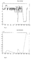
- Figs. 5 and 6 The principle of operation of the filtering according to equation (11) and (13) shall be illustrated by means of Figs. 5 and 6.
- the different fault situations can be seen from Fig. 5, but a better possibility of identification is present when monitoring the fault indicators S ⁇ 1 , i and S ⁇ 2 , i , the behaviour of which can seen in Fig. 6, where the dot-dash line denotes S ⁇ 1 , i and the continuous line denotes the S ⁇ 2 , i .
- the value of the fault indicators S ⁇ 1 , i , S ⁇ 2 , i is on the y-axis and the time in minutes is on the x-axis.
- An alarm can be triggered when S ⁇ 2 , i exceeds a value of e.g. 0.2x10 9 .
- a value of e.g. 0.2x10 9 e.g. 0.2x10 9 .
- the fault indicators S ⁇ 1 , i , S ⁇ 2 , i could be set back to zero, when the refrigeration system has been working faultless long enough.
- the fault indicators S ⁇ 1 , i , S ⁇ 2 , i would anyway be set to zero when a fault is corrected.
- a further advantage of the device is that it may be retrofitted to any refrigeration or heat pump system without any major intervention in the refrigeration system.
- the device uses signals from sensors, which are normally already present in the refrigeration system, or sensors, which can be retrofitted at a very low price.
Landscapes
- Engineering & Computer Science (AREA)
- Physics & Mathematics (AREA)
- Mechanical Engineering (AREA)
- Thermal Sciences (AREA)
- General Engineering & Computer Science (AREA)
- Air Conditioning Control Device (AREA)
- Devices That Are Associated With Refrigeration Equipment (AREA)
- Investigating Or Analyzing Materials By The Use Of Electric Means (AREA)
- Investigating Or Analyzing Materials Using Thermal Means (AREA)
- Investigating Or Analyzing Materials By The Use Of Fluid Adsorption Or Reactions (AREA)
Claims (17)
- Verfahren zur Bestimmung von Entspannungsgas (flashgas) in einem Dampfverdichtungskälte- oder -wärmepumpensystem mit einem Verdichter, einem Kondensator, einem Expansionsgerät und einem Verdampfer, die durch Rohre mit einander verbunden sind zur Bildung eines Durchflussweges für ein Kältemittel, gekennzeichnet durch die Bestimmung eines ersten Wärmestroms eines Wärmetauscherfluids über einen Wärmetauscher des Systems und eines zweiten Wärmestroms des Kältemittels über den Wärmetauscher, wobei die Wärmeströme angewandt werden um ein Energiegleichgewicht zu erzeugen, von dem ein Parameter zur Überwachung des Kältemitteldurchflusses abgeleitet wird.
- Verfahren nach Anspruch 1, dadurch gekennzeichnet, dass der Wärmetauscher der Verdampfer ist.
- Verfahren nach Anspruch 1, dadurch gekennzeichnet, dass der Wärmetauscher der Kondensator ist.
- Verfahren nach einem der vorhergehenden Ansprüche, gekennzeichnet durch die Bestimmung des ersten Wärmestroms durch die Bestimmung eines Wärmetauscherfluid-Massendurchflusses und einer spezifischen Enthalpieänderung des Wärmetauscherfluids über den Wärmetauscher.
- Verfahren nach Anspruch 4, gekennzeichnet durch die Bestimmung des Wärmetauscherfluid-Massendurchflusses als Konstante auf Grund von empirischen Daten oder Daten, die während eines störfreien Systembetriebs eingesammelt worden sind.
- Verfahren nach Anspruch 4 oder 5, gekennzeichnet durch die Bestimmung einer spezifischen Enthalpieänderung des Wärmetauscherfluids über den Wärmetauscher auf Grund von Messungen der Wärmetauscherfluidtemperatur vor und nach dem Wärmetauscher.
- Verfahren nach einem der vorherigen Ansprüche, gekennzeichnet durch die Bestimmung des zweiten Wärmestroms durch die Bestimmung eines Kältemittelmassendurchflusses und einer spezifischen Enthalpieänderung des Kältemittels über den Wärmetauscher.
- Verfahren nach Anspruch 7, gekennzeichnet durch die Bestimmung des Kältemittelmassendurchflusses auf Grund einer Durchflusscharakteristik des Expansionsgerätes, der Öffnungspassage und/oder des Öffnungszeitraums des Expansionsgerätes und eines absoluten Drucks vor und nach dem Expansionsgerät, und, wenn nötig, jegliche Unterkühlung des Kältemittels am Expansionsgeräteinlass.
- Verfahren nach Anspruch 7 oder 8, gekennzeichnet durch die Bestimmung der spezifischen Enthalpiedifferenz des Kältemitteldurchflusses auf Grund der Registrierung der Temperatur und des Drucks des Kältemittels am Expansionsgeräteinlass und der Registrierung der Kältemittelverdampferausgangstemperatur und des Kältemittelverdampferausgangsdrucks oder der Sättigungstemperatur des Kältemittels am Verdampfereinlass.
- Verfahren nach einem der Ansprüche 1-9, gekennzeichnet durch die Bestimmung eines Restwerts als Differenz zwischen des ersten Wärmestroms und des zweiten Wärmestroms.
- Verfahren nach Anspruch 10, gekennzeichnet durch die Angabe einer Fehleranzeige mit Hilfe des Restwertes, wobei die Fehleranzeige nach der folgenden Formel angegeben wird:

wobei S µ1 ,i nach der folgenden Gleichung berechnet wird:
wori: Restwertk1: Proportionalitätskonstanteµ0: erster Empfindlichkeitswertµ1: zweiter Empfindlichkeitswert - Ein Entspannungsgas-Bestimmungsgerät für ein Dampfverdichtungskälte- oder -wärmepumpensystem mit einem Kompressor, einem Kondensator, einem Expansionsgerät und einem Verdampfer, die durch Rohre gegenseitig verbunden sind und einen Durchflussweg für ein Kältemittel bilden, dadurch gekennzeichnet, dass das Gerät Mittel zur Bestimmung eines ersten Wärmestroms eines Wärmetauscher-Fluiddurchflusses über einen Wärmetauscher des Systems und eines zweiten Wärmestroms des Kältemittels über den Wärmetauscher, wobei die Wärmeströme zur Etablierung eines Energiegleichgewichts angewandt werden um ein Parameter zur Überwachung des Kältemitteldurchflusses abzuleiten, wobei das Gerät zusätzlich Bewertungsmittel zur Bewertung des Kältemittelmassendurchflusses aufweist, und ein Ausgangssignal erzeugen.
- Ein Gerät nach Anspruch 12, dadurch gekennzeichnet, dass die Mittel zur Bestimmung des ersten Wärmestroms Mittel zur Bestimmung der Wärmetauscherfluidtemperatur vor und nach einem Wärmetauscher aufweisen.
- Ein Gerät nach Anspruch 12 oder 13, dadurch gekennzeichnet, dass die Mittel zur Bestimmung des zweiten Wärmestroms Mittel zur Bestimmung der Kältemitteltemperatur und des Kältemitteldrucks am Expansionsgeräteinlass und Mittel zur Bestimmung des Drucks am Expansionsgerätauslass oder der Sättigungstemperatur aufweisen.
- Ein Gerät nach einem der Ansprüche 12-14, dadurch gekennzeichnet, dass die Mittel zur Bestimmung des zweiten Wärmestroms Mittel zur Bestimmung des absoluten Kältemitteldrucks vor und nach dem Expansionsgerät und Mittel zur Bestimmung einer Öffnungspassage oder eines Öffnungszeitraums des Expansionsgeräts aufweisen.
- Ein Gerät nach einem der Ansprüche 12-15, dadurch gekennzeichnet, dass die Bewertungsmittel Mittel zur Bestimmung eines Restwertes als Differenz zwischen einem ersten Wert, bestehend aus dem Massendurchfluss des Wärmetauscher-Fluiddurchflusses und der spezifischen Enthalpieänderung über den Wärmetauscher des Systems, und einem zweiten Wert, bestehend aus dem Kältemittelmassendurchfluss und der spezifischen Kältemittelenthalpieänderung über einen Wärmetauscher des Systems, aufweisen.
- Ein Gerät nach einem der Ansprüche 12-16, dadurch gekennzeichnet, dass das Gerät zusätzlich Speichermittel zur Speicherung des Ausgangssignals und Mittels zum Vergleichen dieses Ausgangssignals mit einem früher gespeicherten Ausgangssignal aufweist.
Applications Claiming Priority (3)
| Application Number | Priority Date | Filing Date | Title |
|---|---|---|---|
| DK200201072 | 2002-07-08 | ||
| DKPA200201072 | 2002-07-08 | ||
| PCT/DK2003/000468 WO2004005812A1 (en) | 2002-07-08 | 2003-07-03 | A method and a device for detecting flash gas |
Publications (2)
| Publication Number | Publication Date |
|---|---|
| EP1535006A1 EP1535006A1 (de) | 2005-06-01 |
| EP1535006B1 true EP1535006B1 (de) | 2006-10-18 |
Family
ID=30011009
Family Applications (1)
| Application Number | Title | Priority Date | Filing Date |
|---|---|---|---|
| EP03735336A Expired - Lifetime EP1535006B1 (de) | 2002-07-08 | 2003-07-03 | Verfahren und vorrichtung für das entdecken von flash gas |
Country Status (8)
| Country | Link |
|---|---|
| US (1) | US7681407B2 (de) |
| EP (1) | EP1535006B1 (de) |
| JP (1) | JP4009288B2 (de) |
| AT (1) | ATE343110T1 (de) |
| AU (1) | AU2003236826A1 (de) |
| DE (1) | DE60309181T2 (de) |
| DK (1) | DK1535006T3 (de) |
| WO (1) | WO2004005812A1 (de) |
Families Citing this family (11)
| Publication number | Priority date | Publication date | Assignee | Title |
|---|---|---|---|---|
| DE10217974B4 (de) * | 2002-04-22 | 2004-09-16 | Danfoss A/S | Verfahren zum Auswerten einer nicht gemessenen Betriebsgröße in einer Kälteanlage |
| DE10217975B4 (de) * | 2002-04-22 | 2004-08-19 | Danfoss A/S | Verfahren zum Entdecken von Änderungen in einem ersten Medienstrom eines Wärme- oder Kältetransportmediums in einer Kälteanlage |
| ES2561829T3 (es) * | 2002-10-15 | 2016-03-01 | Danfoss A/S | Un procedimiento para detectar una anomalía de un intercambiador de calor |
| SE529598C2 (sv) * | 2006-02-01 | 2007-10-02 | Svenning Ericsson | Flödeskontroll av köldmedia |
| EP2065641A3 (de) * | 2007-11-28 | 2010-06-09 | Siemens Aktiengesellschaft | Verfahren zum Betrieben eines Durchlaufdampferzeugers sowie Zwangdurchlaufdampferzeuger |
| US7878007B2 (en) * | 2008-02-15 | 2011-02-01 | International Business Machines Corporation | Monitoring method and system for determining airflow rate through and heat removal rate of an air-conditioning unit |
| JP4975168B2 (ja) * | 2009-02-13 | 2012-07-11 | 東芝キヤリア株式会社 | 二次ポンプ方式熱源システム及び二次ポンプ方式熱源制御方法 |
| JP2014006151A (ja) * | 2012-06-25 | 2014-01-16 | Taiyo Nippon Sanso Corp | 液体材料有無検知方法 |
| US9864847B2 (en) * | 2014-09-04 | 2018-01-09 | Robert A. Bellantone | Method for predicting the solubility of a molecule in a polymer at a given temperature |
| DE102015211960A1 (de) * | 2015-06-26 | 2016-12-29 | BSH Hausgeräte GmbH | Kältegerät mit Luftfeuchteüberwachung |
| CN115420534B (zh) * | 2022-09-06 | 2026-02-17 | 合肥通用机械研究院有限公司 | 一种热泵机组测试系统和测试方法 |
Family Cites Families (61)
| Publication number | Priority date | Publication date | Assignee | Title |
|---|---|---|---|---|
| US2295992A (en) * | 1941-01-09 | 1942-09-15 | Chrysler Corp | Flash gas control for refrigerating systems |
| US3171462A (en) | 1962-10-10 | 1965-03-02 | Jr Thodore J Reinhart | Toroidal pneumatic tire |
| US3707851A (en) | 1970-10-28 | 1973-01-02 | Mach Ice Co | Refrigeration system efficiency monitor |
| US3918300A (en) | 1974-01-03 | 1975-11-11 | Aaron Weisstuch | Heat transfer measuring device |
| DE2451361A1 (de) | 1974-10-29 | 1976-05-06 | Jakob | Verfahren zum regeln einer kompressorkuehlanlage |
| US4136528A (en) | 1977-01-13 | 1979-01-30 | Mcquay-Perfex Inc. | Refrigeration system subcooling control |
| US4193781A (en) | 1978-04-28 | 1980-03-18 | Mcquay-Perfex Inc. | Head pressure control for heat reclaim refrigeration systems |
| CA1146650A (en) | 1979-10-01 | 1983-05-17 | Borg-Warner Corporation | Microcomputer based fault detection and indicator control system |
| JPS5919273B2 (ja) | 1979-12-05 | 1984-05-04 | 株式会社日立製作所 | 復水器性能監視方法 |
| SE8006391L (sv) | 1980-09-12 | 1982-03-13 | Jacob Weitman | Sett att reglera en vermevexlare |
| US4325223A (en) | 1981-03-16 | 1982-04-20 | Cantley Robert J | Energy management system for refrigeration systems |
| JPS591970A (ja) | 1982-06-25 | 1984-01-07 | 株式会社日立製作所 | 冷媒流量制御装置 |
| US4510576A (en) | 1982-07-26 | 1985-04-09 | Honeywell Inc. | Specific coefficient of performance measuring device |
| US4479727A (en) | 1982-09-01 | 1984-10-30 | Carrier Corporation | Apparatus and method for evaluating the performance of a heat exchanger |
| SE439063B (sv) | 1983-06-02 | 1985-05-28 | Henrik Sven Enstrom | Forfarande och anordning for provning och prestandaovervakning vid vermepumpar och kylanleggningar |
| US4614087A (en) | 1983-08-09 | 1986-09-30 | Nihon Radiator Co., Ltd. | Apparatus for alarming abnormal coolant in space cooling cycle |
| US4766553A (en) | 1984-03-23 | 1988-08-23 | Azmi Kaya | Heat exchanger performance monitor |
| KR890001890B1 (ko) | 1984-03-23 | 1989-05-30 | 더 뱁콕 앤드 윌콕스 컴퍼니 | 열교환기 성능 감지기 |
| US4621502A (en) | 1985-01-11 | 1986-11-11 | Tyler Refrigeration Corporation | Electronic temperature control for refrigeration system |
| CH670311A5 (de) | 1985-06-17 | 1989-05-31 | Bbc Brown Boveri & Cie | |
| SE454020B (sv) | 1986-02-21 | 1988-03-21 | Etm Metteknik Ab | Sett for bestemning av en kylprocess genom antagande om vissa parametrar, framfor allt kompressorverkningsgraden |
| JPS6371625A (ja) | 1986-09-16 | 1988-04-01 | Mitsubishi Heavy Ind Ltd | 伝熱管の熱吸収量計測装置 |
| US4768346A (en) | 1987-08-26 | 1988-09-06 | Honeywell Inc. | Determining the coefficient of performance of a refrigeration system |
| US4885914A (en) | 1987-10-05 | 1989-12-12 | Honeywell Inc. | Coefficient of performance deviation meter for vapor compression type refrigeration systems |
| JPH01174870A (ja) | 1987-12-28 | 1989-07-11 | Toshiba Corp | 冷凍機診断装置 |
| GB9008788D0 (en) | 1990-04-19 | 1990-06-13 | Whitbread & Co Plc | Diagnostic equipment |
| EP0470676A3 (en) | 1990-08-09 | 1992-09-16 | Riccius + Stroschen Gmbh | Procedure to determine the state of clogging of heat conducting tubes |
| US5079930A (en) * | 1990-12-03 | 1992-01-14 | Atron, Inc. | Apparatus and method for monitoring refrigeration system |
| DE4119020A1 (de) | 1991-06-09 | 1992-12-10 | Braun Ag | Haartrockner |
| DE4207144A1 (de) | 1992-03-06 | 1993-09-09 | Bayer Ag | Verfahren zur regelung von waermeuebertragern |
| JPH05264136A (ja) | 1992-03-24 | 1993-10-12 | Mitsubishi Electric Corp | 空気調和機の熱交換器汚れ検出装置 |
| US5289692A (en) | 1993-01-19 | 1994-03-01 | Parker-Hannifin Corporation | Apparatus and method for mass flow control of a working fluid |
| US5341649A (en) | 1993-03-05 | 1994-08-30 | Future Controls, Inc. | Heat transfer system method and apparatus |
| JPH07234043A (ja) | 1994-02-22 | 1995-09-05 | Hitachi Building Syst Eng & Service Co Ltd | 空調設備における室内側熱交換器の能力把握方法 |
| US5623426A (en) | 1994-02-23 | 1997-04-22 | Sanyo Electric Co., Ltd. | Failure diagnosing system for absorption chillers |
| US5457965A (en) * | 1994-04-11 | 1995-10-17 | Ford Motor Company | Low refrigerant charge detection system |
| US5596507A (en) | 1994-08-15 | 1997-01-21 | Jones; Jeffrey K. | Method and apparatus for predictive maintenance of HVACR systems |
| US5623834A (en) | 1995-05-03 | 1997-04-29 | Copeland Corporation | Diagnostics for a heating and cooling system |
| US5615733A (en) | 1996-05-01 | 1997-04-01 | Helio-Compatic Corporation | On-line monitoring system of a simulated heat-exchanger |
| US6128910A (en) | 1997-02-06 | 2000-10-10 | Federal Air Conditioning Technologies, Inc. | Diagnostic unit for an air conditioning system |
| US6300802B1 (en) * | 1999-02-19 | 2001-10-09 | Applied Micro Circuits Corporation | Output buffer with programmable voltage swing |
| US6089033A (en) | 1999-02-26 | 2000-07-18 | Dube; Serge | High-speed evaporator defrost system |
| US6321564B1 (en) | 1999-03-15 | 2001-11-27 | Denso Corporation | Refrigerant cycle system with expansion energy recovery |
| US6225907B1 (en) | 1999-05-14 | 2001-05-01 | International Comfort Products Corporation (Usa) | Environmental control system incipient failure indicator apparatus |
| US6223544B1 (en) * | 1999-08-05 | 2001-05-01 | Johnson Controls Technology Co. | Integrated control and fault detection of HVAC equipment |
| US6330802B1 (en) | 2000-02-22 | 2001-12-18 | Behr Climate Systems, Inc. | Refrigerant loss detection |
| JP2001255046A (ja) * | 2000-03-13 | 2001-09-21 | Sanyo Electric Co Ltd | 冷凍装置 |
| US6272868B1 (en) | 2000-03-15 | 2001-08-14 | Carrier Corporation | Method and apparatus for indicating condenser coil performance on air-cooled chillers |
| GB0014972D0 (en) * | 2000-06-19 | 2000-08-09 | Borealis Tech Oy | Degassing apparatus |
| CA2344908C (en) | 2000-07-20 | 2010-06-15 | Siemens Building Technologies, Inc. | Model based fault detection and diagnosis methodology for hvac subsystems |
| US7139564B2 (en) | 2000-08-08 | 2006-11-21 | Hebert Thomas H | Wireless communication device for field personnel |
| US6460358B1 (en) * | 2000-11-13 | 2002-10-08 | Thomas H. Hebert | Flash gas and superheat eliminator for evaporators and method therefor |
| JP3951711B2 (ja) | 2001-04-03 | 2007-08-01 | 株式会社デンソー | 蒸気圧縮式冷凍サイクル |
| EP1393004B1 (de) | 2001-05-03 | 2008-08-27 | Matts Lindgren | Verfahren und anordnung zur steuerung der temperatur des abgehenden stroms von einem wärmetauscher und messung von erzeugter hitze |
| US6658373B2 (en) | 2001-05-11 | 2003-12-02 | Field Diagnostic Services, Inc. | Apparatus and method for detecting faults and providing diagnostics in vapor compression cycle equipment |
| US6701725B2 (en) | 2001-05-11 | 2004-03-09 | Field Diagnostic Services, Inc. | Estimating operating parameters of vapor compression cycle equipment |
| US6590362B2 (en) * | 2001-07-27 | 2003-07-08 | Texas A&M University System | Method and system for early detection of incipient faults in electric motors |
| DE10217974B4 (de) | 2002-04-22 | 2004-09-16 | Danfoss A/S | Verfahren zum Auswerten einer nicht gemessenen Betriebsgröße in einer Kälteanlage |
| DE10217975B4 (de) | 2002-04-22 | 2004-08-19 | Danfoss A/S | Verfahren zum Entdecken von Änderungen in einem ersten Medienstrom eines Wärme- oder Kältetransportmediums in einer Kälteanlage |
| US6973793B2 (en) | 2002-07-08 | 2005-12-13 | Field Diagnostic Services, Inc. | Estimating evaporator airflow in vapor compression cycle cooling equipment |
| ES2561829T3 (es) | 2002-10-15 | 2016-03-01 | Danfoss A/S | Un procedimiento para detectar una anomalía de un intercambiador de calor |
-
2003
- 2003-07-03 WO PCT/DK2003/000468 patent/WO2004005812A1/en not_active Ceased
- 2003-07-03 DK DK03735336T patent/DK1535006T3/da active
- 2003-07-03 AU AU2003236826A patent/AU2003236826A1/en not_active Abandoned
- 2003-07-03 AT AT03735336T patent/ATE343110T1/de not_active IP Right Cessation
- 2003-07-03 JP JP2004518469A patent/JP4009288B2/ja not_active Expired - Fee Related
- 2003-07-03 DE DE60309181T patent/DE60309181T2/de not_active Expired - Lifetime
- 2003-07-03 US US10/520,337 patent/US7681407B2/en not_active Expired - Fee Related
- 2003-07-03 EP EP03735336A patent/EP1535006B1/de not_active Expired - Lifetime
Also Published As
| Publication number | Publication date |
|---|---|
| DE60309181T2 (de) | 2007-08-30 |
| US20050166609A1 (en) | 2005-08-04 |
| US7681407B2 (en) | 2010-03-23 |
| DE60309181D1 (de) | 2006-11-30 |
| WO2004005812A1 (en) | 2004-01-15 |
| ATE343110T1 (de) | 2006-11-15 |
| JP2005532523A (ja) | 2005-10-27 |
| DK1535006T3 (da) | 2007-02-26 |
| EP1535006A1 (de) | 2005-06-01 |
| AU2003236826A1 (en) | 2004-01-23 |
| JP4009288B2 (ja) | 2007-11-14 |
Similar Documents
| Publication | Publication Date | Title |
|---|---|---|
| US8100167B2 (en) | Method and a device for detecting an abnormality of a heat exchanger, and the use of such a device | |
| EP1852664B1 (de) | Klimaanlage | |
| US7631508B2 (en) | Apparatus and method for determining refrigerant charge level | |
| Li et al. | Development, evaluation, and demonstration of a virtual refrigerant charge sensor | |
| US7685830B2 (en) | Method for detecting changes in a first media flow of a heat or cooling medium in a refrigeration system | |
| Grace et al. | Sensitivity of refrigeration system performance to charge levels and parameters for on-line leak detection | |
| DK2812640T3 (en) | PROCEDURE FOR DETECTING LOSS OF REFRIGERANT | |
| US8775123B2 (en) | Method for determination of the coefficient of performanace of a refrigerating machine | |
| EP1535006B1 (de) | Verfahren und vorrichtung für das entdecken von flash gas | |
| US20180340719A1 (en) | Detection of lack of refrigerant in a cooling system having multiple cooling locations | |
| JP5787604B2 (ja) | 車両用空気調和装置故障診断システム及び故障診断装置 | |
| Li et al. | Virtual refrigerant pressure sensors for use in monitoring and fault diagnosis of vapor-compression equipment | |
| US6308523B1 (en) | Simplified subcooling or superheated indicator and method for air conditioning and other refrigeration systems | |
| Wichman et al. | Fault detection and diagnostics for commercial coolers and freezers | |
| GB2260816A (en) | Monitoring fluid quantities | |
| CN115485513A (zh) | 用于监测蒸气压缩系统中的制冷剂充注量的方法 | |
| JPH0493567A (ja) | 冷凍機の性能診断装置 | |
| US20160169568A1 (en) | Refrigerant level monitor for refrigeration system | |
| JPH07218058A (ja) | 適正冷媒量判定機能付き冷凍空調装置 | |
| EP4332467A1 (de) | Verfahren zur bewertung der kühlmittelladung in einem kühlkreislauf | |
| JPH05157416A (ja) | 吸収式冷凍機の異常検出装置 |
Legal Events
| Date | Code | Title | Description |
|---|---|---|---|
| PUAI | Public reference made under article 153(3) epc to a published international application that has entered the european phase |
Free format text: ORIGINAL CODE: 0009012 |
|
| 17P | Request for examination filed |
Effective date: 20050128 |
|
| AK | Designated contracting states |
Kind code of ref document: A1 Designated state(s): AT BE BG CH CY CZ DE DK EE ES FI FR GB GR HU IE IT LI LU MC NL PT RO SE SI SK TR |
|
| AX | Request for extension of the european patent |
Extension state: LT LV MK |
|
| DAX | Request for extension of the european patent (deleted) | ||
| GRAP | Despatch of communication of intention to grant a patent |
Free format text: ORIGINAL CODE: EPIDOSNIGR1 |
|
| GRAS | Grant fee paid |
Free format text: ORIGINAL CODE: EPIDOSNIGR3 |
|
| GRAA | (expected) grant |
Free format text: ORIGINAL CODE: 0009210 |
|
| AK | Designated contracting states |
Kind code of ref document: B1 Designated state(s): AT BE BG CH CY CZ DE DK EE ES FI FR GB GR HU IE IT LI LU MC NL PT RO SE SI SK TR |
|
| PG25 | Lapsed in a contracting state [announced via postgrant information from national office to epo] |
Ref country code: RO Free format text: LAPSE BECAUSE OF FAILURE TO SUBMIT A TRANSLATION OF THE DESCRIPTION OR TO PAY THE FEE WITHIN THE PRESCRIBED TIME-LIMIT Effective date: 20061018 Ref country code: NL Free format text: LAPSE BECAUSE OF FAILURE TO SUBMIT A TRANSLATION OF THE DESCRIPTION OR TO PAY THE FEE WITHIN THE PRESCRIBED TIME-LIMIT Effective date: 20061018 Ref country code: FI Free format text: LAPSE BECAUSE OF FAILURE TO SUBMIT A TRANSLATION OF THE DESCRIPTION OR TO PAY THE FEE WITHIN THE PRESCRIBED TIME-LIMIT Effective date: 20061018 Ref country code: BE Free format text: LAPSE BECAUSE OF FAILURE TO SUBMIT A TRANSLATION OF THE DESCRIPTION OR TO PAY THE FEE WITHIN THE PRESCRIBED TIME-LIMIT Effective date: 20061018 Ref country code: SK Free format text: LAPSE BECAUSE OF FAILURE TO SUBMIT A TRANSLATION OF THE DESCRIPTION OR TO PAY THE FEE WITHIN THE PRESCRIBED TIME-LIMIT Effective date: 20061018 Ref country code: AT Free format text: LAPSE BECAUSE OF FAILURE TO SUBMIT A TRANSLATION OF THE DESCRIPTION OR TO PAY THE FEE WITHIN THE PRESCRIBED TIME-LIMIT Effective date: 20061018 Ref country code: CH Free format text: LAPSE BECAUSE OF FAILURE TO SUBMIT A TRANSLATION OF THE DESCRIPTION OR TO PAY THE FEE WITHIN THE PRESCRIBED TIME-LIMIT Effective date: 20061018 Ref country code: SI Free format text: LAPSE BECAUSE OF FAILURE TO SUBMIT A TRANSLATION OF THE DESCRIPTION OR TO PAY THE FEE WITHIN THE PRESCRIBED TIME-LIMIT Effective date: 20061018 Ref country code: LI Free format text: LAPSE BECAUSE OF FAILURE TO SUBMIT A TRANSLATION OF THE DESCRIPTION OR TO PAY THE FEE WITHIN THE PRESCRIBED TIME-LIMIT Effective date: 20061018 Ref country code: CZ Free format text: LAPSE BECAUSE OF FAILURE TO SUBMIT A TRANSLATION OF THE DESCRIPTION OR TO PAY THE FEE WITHIN THE PRESCRIBED TIME-LIMIT Effective date: 20061018 |
|
| REG | Reference to a national code |
Ref country code: GB Ref legal event code: FG4D |
|
| REG | Reference to a national code |
Ref country code: CH Ref legal event code: EP Ref country code: IE Ref legal event code: FG4D |
|
| REF | Corresponds to: |
Ref document number: 60309181 Country of ref document: DE Date of ref document: 20061130 Kind code of ref document: P |
|
| PG25 | Lapsed in a contracting state [announced via postgrant information from national office to epo] |
Ref country code: BG Free format text: LAPSE BECAUSE OF FAILURE TO SUBMIT A TRANSLATION OF THE DESCRIPTION OR TO PAY THE FEE WITHIN THE PRESCRIBED TIME-LIMIT Effective date: 20070118 Ref country code: SE Free format text: LAPSE BECAUSE OF FAILURE TO SUBMIT A TRANSLATION OF THE DESCRIPTION OR TO PAY THE FEE WITHIN THE PRESCRIBED TIME-LIMIT Effective date: 20070118 |
|
| PG25 | Lapsed in a contracting state [announced via postgrant information from national office to epo] |
Ref country code: ES Free format text: LAPSE BECAUSE OF FAILURE TO SUBMIT A TRANSLATION OF THE DESCRIPTION OR TO PAY THE FEE WITHIN THE PRESCRIBED TIME-LIMIT Effective date: 20070129 |
|
| REG | Reference to a national code |
Ref country code: DK Ref legal event code: T3 |
|
| PG25 | Lapsed in a contracting state [announced via postgrant information from national office to epo] |
Ref country code: PT Free format text: LAPSE BECAUSE OF FAILURE TO SUBMIT A TRANSLATION OF THE DESCRIPTION OR TO PAY THE FEE WITHIN THE PRESCRIBED TIME-LIMIT Effective date: 20070319 |
|
| NLV1 | Nl: lapsed or annulled due to failure to fulfill the requirements of art. 29p and 29m of the patents act | ||
| ET | Fr: translation filed | ||
| REG | Reference to a national code |
Ref country code: CH Ref legal event code: PL |
|
| PLBE | No opposition filed within time limit |
Free format text: ORIGINAL CODE: 0009261 |
|
| STAA | Information on the status of an ep patent application or granted ep patent |
Free format text: STATUS: NO OPPOSITION FILED WITHIN TIME LIMIT |
|
| 26N | No opposition filed |
Effective date: 20070719 |
|
| PG25 | Lapsed in a contracting state [announced via postgrant information from national office to epo] |
Ref country code: MC Free format text: LAPSE BECAUSE OF NON-PAYMENT OF DUE FEES Effective date: 20070731 Ref country code: GR Free format text: LAPSE BECAUSE OF FAILURE TO SUBMIT A TRANSLATION OF THE DESCRIPTION OR TO PAY THE FEE WITHIN THE PRESCRIBED TIME-LIMIT Effective date: 20070119 |
|
| PG25 | Lapsed in a contracting state [announced via postgrant information from national office to epo] |
Ref country code: IE Free format text: LAPSE BECAUSE OF NON-PAYMENT OF DUE FEES Effective date: 20070703 |
|
| PG25 | Lapsed in a contracting state [announced via postgrant information from national office to epo] |
Ref country code: EE Free format text: LAPSE BECAUSE OF FAILURE TO SUBMIT A TRANSLATION OF THE DESCRIPTION OR TO PAY THE FEE WITHIN THE PRESCRIBED TIME-LIMIT Effective date: 20061018 |
|
| PG25 | Lapsed in a contracting state [announced via postgrant information from national office to epo] |
Ref country code: LU Free format text: LAPSE BECAUSE OF NON-PAYMENT OF DUE FEES Effective date: 20070703 Ref country code: CY Free format text: LAPSE BECAUSE OF FAILURE TO SUBMIT A TRANSLATION OF THE DESCRIPTION OR TO PAY THE FEE WITHIN THE PRESCRIBED TIME-LIMIT Effective date: 20061018 |
|
| PG25 | Lapsed in a contracting state [announced via postgrant information from national office to epo] |
Ref country code: TR Free format text: LAPSE BECAUSE OF FAILURE TO SUBMIT A TRANSLATION OF THE DESCRIPTION OR TO PAY THE FEE WITHIN THE PRESCRIBED TIME-LIMIT Effective date: 20061018 Ref country code: HU Free format text: LAPSE BECAUSE OF FAILURE TO SUBMIT A TRANSLATION OF THE DESCRIPTION OR TO PAY THE FEE WITHIN THE PRESCRIBED TIME-LIMIT Effective date: 20070419 |
|
| PGFP | Annual fee paid to national office [announced via postgrant information from national office to epo] |
Ref country code: DK Payment date: 20140710 Year of fee payment: 12 |
|
| REG | Reference to a national code |
Ref country code: FR Ref legal event code: PLFP Year of fee payment: 13 |
|
| REG | Reference to a national code |
Ref country code: DK Ref legal event code: EBP Effective date: 20150731 |
|
| REG | Reference to a national code |
Ref country code: FR Ref legal event code: PLFP Year of fee payment: 14 |
|
| PG25 | Lapsed in a contracting state [announced via postgrant information from national office to epo] |
Ref country code: DK Free format text: LAPSE BECAUSE OF NON-PAYMENT OF DUE FEES Effective date: 20150731 |
|
| REG | Reference to a national code |
Ref country code: FR Ref legal event code: PLFP Year of fee payment: 15 |
|
| REG | Reference to a national code |
Ref country code: FR Ref legal event code: PLFP Year of fee payment: 16 |
|
| REG | Reference to a national code |
Ref country code: DE Ref legal event code: R082 Ref document number: 60309181 Country of ref document: DE Representative=s name: KEIL & SCHAAFHAUSEN PATENTANWAELTE PARTGMBB, DE Ref country code: DE Ref legal event code: R082 Ref document number: 60309181 Country of ref document: DE Representative=s name: KEIL & SCHAAFHAUSEN PATENT- UND RECHTSANWAELTE, DE |
|
| PGFP | Annual fee paid to national office [announced via postgrant information from national office to epo] |
Ref country code: FR Payment date: 20200625 Year of fee payment: 18 |
|
| PGFP | Annual fee paid to national office [announced via postgrant information from national office to epo] |
Ref country code: GB Payment date: 20200624 Year of fee payment: 18 |
|
| PGFP | Annual fee paid to national office [announced via postgrant information from national office to epo] |
Ref country code: DE Payment date: 20200624 Year of fee payment: 18 |
|
| PGFP | Annual fee paid to national office [announced via postgrant information from national office to epo] |
Ref country code: IT Payment date: 20200610 Year of fee payment: 18 |
|
| REG | Reference to a national code |
Ref country code: DE Ref legal event code: R119 Ref document number: 60309181 Country of ref document: DE |
|
| GBPC | Gb: european patent ceased through non-payment of renewal fee |
Effective date: 20210703 |
|
| PG25 | Lapsed in a contracting state [announced via postgrant information from national office to epo] |
Ref country code: GB Free format text: LAPSE BECAUSE OF NON-PAYMENT OF DUE FEES Effective date: 20210703 Ref country code: DE Free format text: LAPSE BECAUSE OF NON-PAYMENT OF DUE FEES Effective date: 20220201 |
|
| PG25 | Lapsed in a contracting state [announced via postgrant information from national office to epo] |
Ref country code: FR Free format text: LAPSE BECAUSE OF NON-PAYMENT OF DUE FEES Effective date: 20210731 |
|
| PG25 | Lapsed in a contracting state [announced via postgrant information from national office to epo] |
Ref country code: IT Free format text: LAPSE BECAUSE OF NON-PAYMENT OF DUE FEES Effective date: 20210703 |