EP1534973B1 - Dämpfer für ein hydraulisches kupplungsbetätigungssystem - Google Patents
Dämpfer für ein hydraulisches kupplungsbetätigungssystem Download PDFInfo
- Publication number
- EP1534973B1 EP1534973B1 EP03784358A EP03784358A EP1534973B1 EP 1534973 B1 EP1534973 B1 EP 1534973B1 EP 03784358 A EP03784358 A EP 03784358A EP 03784358 A EP03784358 A EP 03784358A EP 1534973 B1 EP1534973 B1 EP 1534973B1
- Authority
- EP
- European Patent Office
- Prior art keywords
- diaphragm
- damper
- chamber
- tube
- elastomeric
- Prior art date
- Legal status (The legal status is an assumption and is not a legal conclusion. Google has not performed a legal analysis and makes no representation as to the accuracy of the status listed.)
- Expired - Lifetime
Links
- 239000012530 fluid Substances 0.000 claims description 21
- 238000013016 damping Methods 0.000 claims description 11
- 230000004044 response Effects 0.000 claims description 11
- 229910000639 Spring steel Inorganic materials 0.000 claims description 9
- 230000000694 effects Effects 0.000 claims description 9
- 238000004891 communication Methods 0.000 claims description 8
- 230000009977 dual effect Effects 0.000 claims description 4
- 239000013536 elastomeric material Substances 0.000 claims description 3
- 238000009434 installation Methods 0.000 description 3
- 230000002093 peripheral effect Effects 0.000 description 3
- 230000007246 mechanism Effects 0.000 description 2
- 230000009471 action Effects 0.000 description 1
- 230000005540 biological transmission Effects 0.000 description 1
- 230000000994 depressogenic effect Effects 0.000 description 1
- 238000006073 displacement reaction Methods 0.000 description 1
- 239000013013 elastic material Substances 0.000 description 1
- 239000011152 fibreglass Substances 0.000 description 1
- 238000005429 filling process Methods 0.000 description 1
- 238000010304 firing Methods 0.000 description 1
- 230000000670 limiting effect Effects 0.000 description 1
- 239000000463 material Substances 0.000 description 1
- 239000012528 membrane Substances 0.000 description 1
- 239000007769 metal material Substances 0.000 description 1
- 230000007935 neutral effect Effects 0.000 description 1
- 239000004033 plastic Substances 0.000 description 1
- 230000000644 propagated effect Effects 0.000 description 1
- 238000010926 purge Methods 0.000 description 1
- 229910001220 stainless steel Inorganic materials 0.000 description 1
- 239000010935 stainless steel Substances 0.000 description 1
- 239000011800 void material Substances 0.000 description 1
Images


Classifications
-
- F—MECHANICAL ENGINEERING; LIGHTING; HEATING; WEAPONS; BLASTING
- F16—ENGINEERING ELEMENTS AND UNITS; GENERAL MEASURES FOR PRODUCING AND MAINTAINING EFFECTIVE FUNCTIONING OF MACHINES OR INSTALLATIONS; THERMAL INSULATION IN GENERAL
- F16D—COUPLINGS FOR TRANSMITTING ROTATION; CLUTCHES; BRAKES
- F16D25/00—Fluid-actuated clutches
- F16D25/12—Details not specific to one of the before-mentioned types
- F16D25/14—Fluid pressure control
-
- F—MECHANICAL ENGINEERING; LIGHTING; HEATING; WEAPONS; BLASTING
- F16—ENGINEERING ELEMENTS AND UNITS; GENERAL MEASURES FOR PRODUCING AND MAINTAINING EFFECTIVE FUNCTIONING OF MACHINES OR INSTALLATIONS; THERMAL INSULATION IN GENERAL
- F16D—COUPLINGS FOR TRANSMITTING ROTATION; CLUTCHES; BRAKES
- F16D48/00—External control of clutches
- F16D48/02—Control by fluid pressure
- F16D2048/0215—Control by fluid pressure for damping of pulsations within the fluid system
-
- F—MECHANICAL ENGINEERING; LIGHTING; HEATING; WEAPONS; BLASTING
- F16—ENGINEERING ELEMENTS AND UNITS; GENERAL MEASURES FOR PRODUCING AND MAINTAINING EFFECTIVE FUNCTIONING OF MACHINES OR INSTALLATIONS; THERMAL INSULATION IN GENERAL
- F16D—COUPLINGS FOR TRANSMITTING ROTATION; CLUTCHES; BRAKES
- F16D2300/00—Special features for couplings or clutches
- F16D2300/22—Vibration damping
Definitions
- This invention relates to a damper for use in hydraulic actuator systems, according to the preamble portion of claim 1.
- Hydraulic actuator systems are known for operating a mechanism at a remote location by way of a master cylinder connected to a slave cylinder installed at the remote location.
- a conduit Interconnects the master cylinder to the slave cylinder and the system is filled with hydraulic fluid such that, when a piston of the master cylinder is actuated, a piston of the slave cylinder and consequently a piston rod or output member is simultaneously actuated by displacement of the hydraulic fluid from the master cylinder to the slave cylinder through the conduit.
- an elastomeric diaphragm has been proposed for use with a further spring steel diaphragm to provide a dual action diaphragm wherein the elastomeric diaphragm damps low frequency vibrations in the system and the elastomeric diaphragm deforms against the spring steel diaphragm to damp high frequency vibrations in the system.
- a further damper is known from FR-A-2 762 662. This damper, however does not possess a membrane which would be capable of vibrating in a free manner.
- This invention is directed to the provision of an improved damper suitable for use in, for example, a hydraulic clutch actuator system.
- this invention is directed to the provision of an improved damper which eliminates the evacuating and filling problems previously encountered with the use of a stretchable elastomeric diaphragm.
- damper for provision in a hydraulic actuator system between a master cylinder and a slave cylinder of the system, which damper includes:
- This arrangement precludes permanent stretching of the diaphragm during the evacuation and filling operations and allows total evacuation of the chamber and subsequent total filling of the chamber.
- the damper may further include a plurality of circumferentially spaced ribs extending radially outwardly from the tube and each defining a lower edge substantially level with the free lower end of the tube. This arrangement serves to further limit upward excursions of the diaphragm and further preclude permanent stretching of the diaphragm during the evacuation operation.
- the damper may be a dual action damper wherein the elastomeric diaphragm deflects in response to the low frequency vibrations transmitted through the hydraulic fluid in the system to effect damping of low frequency vibrations, and the damper includes a further relatively stiff diaphragm carried by the housing and positioned proximate a lower face of the elastomeric diaphragm so as to form a back up for the elastomeric diaphragm.
- the elastomeric diaphragm may deform against the further diaphragm in response to high frequency vibrations transmitted through the hydraulic fluid to cause deflection of the further diaphragm to effect damping of the high frequency vibrations.
- the hydraulic dutch actuator system shown schematically in Figure 1 indudes a master cylinder 10, a slave cylinder 12, and a conduit 14 extending between the outlet or discharge of the master cylinder and the inlet of the slave cylinder.
- Master cylinder 10 includes an input rod 16 connected in known manner to the clutch pedal 18 of an associated motor vehicle so that pivotal movement of the dutch pedal by the vehide operator moves a piston of the master cylinder in known manner to discharge pressure fluid from the cylinder.
- Cylinder 10 further includes a flange 10a to facilitate attachment of the master cylinder to the firewall 20 of the vehicle.
- Slave cylinder 12 is secured by a bracket 22 to the bell housing 23 enclosing the dutch 24 of the vehide and indudes an output rod 25 coacting in known manner with a dutch release lever 26 so that pivotal movement of dutch pedal 18 by the operator results in discharge or pressure fluid from master cylinder 10 for conveyance through conduit 14 to slave cylinder 12 to provide extension of output rod 25 and pivotal movement of release lever 26 to move the dutch release bearing 27 in a direction to disengage the dutch 24.
- Clutch 24 is driven in known manner by a flywheel 30 which in turn is driven by an engine crank shaft 32.
- the invention damper 36 is interposed in conduit 14 and is connected to the outlet of master cylinder 10 by a conduit portion 14a and to the inlet of slave cylinder 12 by a conduit portion 14b.
- Damper 36 indudes a housing 38, a relatively flexible elastomeric diaphragm 40, a relatively stiff metallic diaphragm 42, and a cover member 44.
- Housing 38 is formed of a suitable plastic material such for example as a glass reinforced plastic and has a generally circular cross-sectional configuration including a main body conical portion 38a defining a damper port 38b and a downwardly opening domed chamber or cavity 38c, a male inlet fitting 38d defining an inlet port 38e communicating with damper port 38b, a male outlet fitting 38f defining an outlet port 38g communicating with damper port 38b, a stop structure 38h, and a lower flange portion 38i.
- a suitable plastic material such for example as a glass reinforced plastic and has a generally circular cross-sectional configuration including a main body conical portion 38a defining a damper port 38b and a downwardly opening domed chamber or cavity 38c, a male inlet fitting 38d defining an inlet port 38e communicating with damper port 38b, a male outlet fitting 38f defining an outlet port 38g communicating with damper port 38b, a stop structure 38h, and a lower flange portion 38i.
- Stop structure 38h includes a tube structure 38j and a plurality of circumferentially spaced ribs 38k extending radially outwardly from tube structure 38j for integral joinder at their arcuate outer edges 381 with the wall surface of chamber 38c whereby to divide the chamber into the plurality of downwardly opening circumferentially spaced compartments centred about tube structures 38j.
- Tube structure 38j communicates at an upper end thereof with the lower end of damper port 38b and defines a plurality of circumferentially spaced apertures 38m proximate the lower free end 38n of the tube structure.
- Each aperture 38m is in the form of a downwardly opening slot positioned between adjacent ribs 38k.
- the lower edges 38p of ribs 38k are substantially level with the free lower end 38n of the tube structure.
- Housing flange portion 38i defines an annular downwardly opening groove 38q.
- Elastomeric diaphragm 40 has a generally circular planar configuration and is formed of a suitable elastic material such as rubber.
- Diaphragm 40 includes an upstanding outer flange portion 40a sized to fit in housing groove 38q and a generally planar central main body portion 40b extending across the lower face of housing 38 and coacting with the housing to define chamber 38c.
- Diaphragm 40 will be seen to have a thin planar configuration including upper and lower parallel faces 40c and 40d and the upper face 40c of the diaphragm will be seen to form a boundary wall of the hydraulic actuator system so that the diaphragm may deflect in response to vibrations transmitted through the hydraulic fluid in the system.
- Diaphragm 42 has a generally circular dished configuration and is preferably formed of spring steel.
- Diaphragm 42 includes a peripheral portion 42a engaging a peripheral portion of the lower face 40d of the elastomeric diaphragm and a central recess or dished portion 42b defining an upper face positioned proximate but spaced below a central portion of the lower face 40d of the elastomeric diaphragm to define a void 46.
- Cover member 44 has a generally circular configuration and is preferably formed of a suitable metallic material.
- Cover member 44 includes a clamping ring portion 44a and a central dished portion 44b.
- Clamping ring portion 44a includes an upper flange 44c clampingly engaging a shoulder 38r on housing flange portion 38i and a lower flange 44d clampingly engaging the underside of the peripheral portion 42a of spring steel diaphragm 42.
- Clamping ring portion 44a will be seen to press diaphragm 42 upwardly against diaphragm 38 and into engagement with housing flange portion 38i whereby to press flange portion 40a of elastomeric diaphragm 40 firmly into groove 38q with central dished portion 44b underlying and spaced downwardly from the central dished portion 42b of diaphragm 42.
- low frequency vibrations for example 0-10 hertz
- transmitted through the hydraulic fluid in the system to the damper have the effect of deflecting the elastomeric diaphragm 40 to effect damping of the low frequency vibrations.
- the damping action of the elastomeric diaphragm with respect to the low frequency vibrations has no affect on the spring steel diaphragm 42.
- stainless steel diaphragm forms a backup for the elastomeric diaphragm and, specifically, elastomeric diaphragm 40 elastically deforms against spring steel diaphragm 42 to seat the lower face 40d of the elastomeric diaphragm against the upper face of the spring steel diaphragm and cause deflection of the spring steel diaphragm whereby to effect damping of the high frequency vibrations.
- damper in order to fill the damper with hydraulic fluid for use in the system it is first necessary to evacuate the damper.
- the damper is inserted into the overall clutch actuator system prior to the evacuating and filling operations, whereafter the overall system including the damper is evacuated and thereafter filled with hydraulic fluid preparatory to shipping the hydraulic clutch actuator as a prefilled assembly to a user for use in known manner on a vehicle to operate the vehicle clutch.
- the diaphragm 40 is made of a stretchable elastomeric material, in the absence of the stop structure 38i, the elastomeric diaphragm would tend to be sucked upwardly into the chamber 38c in response to the evacuation of the system and this upward excursion of the diaphragm into the chamber might result in straining of the diaphragm to a point beyond its elastic limit with the result that the diaphragm would be permanently stretched and would no longer be useable in the damper for its intended damping function.
- the stop structure of the invention effectively limits the upward excursion of the elastomeric diaphragm in response to the applied vacuum to an excursion magnitude well within the elastic limit of the diaphragm, whereby to preclude permanent stretching and resultant disabling of the diaphragm.
- This upward limiting action is provided by the lower end 38n of the tube structure and by the lower edges 38p of the ribs, and the apertures or slots 38m allow the volume of the chamber above the diaphragm to be totally evacuated and thereafter totally filled with hydraulic fluid irrespective of the upward deflection of the diaphragm to the point of closing off the lower end of the tubular structure as seen by the dash lines in Figure 3.
- slots 38m provide communication between the interior of the tube structure and the chamber, whereby to maintain communication between the damper port and the chamber, even with the elastomeric diaphragm pulled upwardly into a position totally closing the free lower end of the tube structure.
- the circumferentially spaced ribs 38k will be seen not only to coact with the stop structure to limit the upward excursion of the elastomeric diaphragm but will also be seen to significantly structurally strengthen the housing 38.
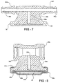
- the modified embodiment of the invention damper seen in Figure 8 is identical to the damper of Figures 1-7 with the exception that the male inlet and outlet fittings 38d and 38f of the Figures 1-7 embodiment are replaced with female inlet and outlet fittings 38t and 38u which coact, in known manner, with male fittings carried on the respective coacting ends of the conduit portions 14a and 14b.
- the invention damper will be seen to be effective to damp the low frequency vibrations typically appearing at the clutch pedal during engine idle conditions with the transmission In neutral as well as the high frequency vibrations appearing in the system during engagement and disengagement of the clutch during normal driving, and will further be seen to insure total filling of the damper with hydraulic fluid in response to the evacuation and filling of the overall clutch actuator system.
Landscapes
- Engineering & Computer Science (AREA)
- General Engineering & Computer Science (AREA)
- Physics & Mathematics (AREA)
- Fluid Mechanics (AREA)
- Mechanical Engineering (AREA)
- Hydraulic Clutches, Magnetic Clutches, Fluid Clutches, And Fluid Joints (AREA)
Claims (6)
- Dämpfer (36) zum Vorsehen in einem hydraulischen Betätigungssystem zwischen einem Geberzylinder (10) und einem Nehmerzylinder (12) des Systems, wobei der Dämpfer (36) umfaßt:ein Gehäuse (38) mit einer Öffnung (38b) zum Anschluß in dem System;eine Membran (40), die durch das Gehäuse (38) getragen ist und mit dem Gehäuse (38) zusammenwirkt, um oberhalb der Membran (40) eine Kammer (38c) zu begrenzen, die mit der Öffnung (38b) in Verbindung steht, so daß die Membran (40) in Antwort auf Schwingungen, die durch die Hydraulikflüssigkeit in dem System übertragen werden, auslenken kann, um eine Dämpfung der Schwingungen zu bewirken, wobei die Membran (40) aus einem elastomeren Material gebildet ist; undeine Anschlagstruktur (38h), die in der Kammer (38c) in einer gegenüberliegenden Beziehung zu der Membran (40) positioniert und wirksam ist, um Aufwärtsauslenkungen der Membran (40) in die Kammer (38c) zu begrenzen auf Auslenkungen innerhalb der elastischen Grenze der Membran (40), wodurch eine permanente Dehnung der Membran (40) verhindert wird;wobei die Anschlagstruktur (38h) ein Durchgangsmittel (38m) umfaßt, das für eine Verbindung zwischen der Öffnung (38b) und der Kammer (38c) unabhängig von der Stellung der Membran (40) relativ zu der Anschlagstruktur (38h) sorgt, wodurch ein vollständiges Leeren der Kammer (38c) und ein nachfolgendes vollständiges Füllen der Kammer (38c) ermöglicht werden;
dadurch gekennzeichnet, daß die Anschlagstruktur (38h) ferner ein Rohr (38j) aufweist, das an seinem oberen Ende mit der Öffnung (38b) kommuniziert, sich nach unten in die Kammer (38c) erstreckt und ein freies unteres Ende (38n) aufweist, welches nahe der Membran (40) positioniert ist;
wobei die Durchgangsmittel Durchgänge (38m) in dem Rohr (38j) aufweisen, die das Innere des Rohrs (38j) mit der Kammer (38c) verbinden, wodurch eine Verbindung zwischen der Öffnung (38b) und der Kammer (38c) selbst dann aufrechterhalten wird, wenn die elastomere Membran (40) nach oben in eine Stellung gezogen wird, in der das freie Ende (38n) des Rohrs (38j) verschlossen wird, wobei jeder Durchgang (38m) einen sich nach unten öffnenden Schlitz aufweist, der in dem unteren Ende (38n) des Rohrs (38j) gebildet ist. - Dämpfer (36) nach Anspruch 1, dadurch gekennzeichnet, daß der Dämpfer (36) ferner eine Mehrzahl von in Umfangsrichtung beabstandeten Rippen (38k) aufweist, die sich von dem Rohr (38j) radial nach außen erstrecken und jeweils eine untere Kante (38p) definieren, die sich im wesentlichen auf einer Höhe mit dem freien Ende (38n) des Rohrs (38j) befindet, wodurch Aufwärtsauslenkungen der Membran (40) weiter begrenzt werden.
- Dämpfer (36) nach Anspruch 1 oder 2, dadurch gekennzeichnet, daß der Dämpfer (36) einen zweifach wirkenden Dämpfer aufweist, wobei die elastomere Membran (40) in Antwort auf Schwingungen niedriger Frequenz auslenkt, die durch die Hydraulikflüssigkeit in dem System übertragen werden, um eine Dämpfung der niederfrequenten Schwingung zu bewirken; und der Dämpfer (36) eine weitere, relativ steife Membran (42) aufweist, die durch das Gehäuse (38) getragen und nahe einer unteren Fläche (40d) der elastomeren Membran (40) positioniert ist, um eine Stütze für die elastomere Membran (40) zu bilden, so daß die elastomere Membran (40) sich in Antwort auf Schwingungen hoher Frequenz, die durch die Hydraulikflüssigkeit übertragen werden, gegen die weitere Membran (42) verformt, um ein Auslenken der weiteren Membran (42) zu verursachen, um eine Dämpfung der hochfrequenten Schwingungen zu bewirken.
- Dämpfer (36) nach Anspruch 3, dadurch gekennzeichnet, daß die weitere Membran (42) eine Federstahlmembran ist.
- Dämpfer (36) nach einem der vorhergehenden Ansprüche, dadurch gekennzeichnet, daß die Kammer (38c) eine Kuppelkonfiguration aufweist.
- Hydraulisches Kupplungsbetätigungssystem, das einen Schwingungsdämpfer (36) nach einem der vorhergehenden Ansprüche zwischen einem Geberzylinder (10) und einem Nehmerzylinder (12) des Systems aufweist.
Applications Claiming Priority (3)
| Application Number | Priority Date | Filing Date | Title |
|---|---|---|---|
| US10/215,632 US6742643B2 (en) | 2002-08-08 | 2002-08-08 | Elastomeric damper for hydraulic clutch actuator |
| US215632 | 2002-08-08 | ||
| PCT/IB2003/003318 WO2004015290A1 (en) | 2002-08-08 | 2003-07-24 | Damper for hydraulic clutch actuator system |
Publications (2)
| Publication Number | Publication Date |
|---|---|
| EP1534973A1 EP1534973A1 (de) | 2005-06-01 |
| EP1534973B1 true EP1534973B1 (de) | 2006-08-30 |
Family
ID=31494913
Family Applications (1)
| Application Number | Title | Priority Date | Filing Date |
|---|---|---|---|
| EP03784358A Expired - Lifetime EP1534973B1 (de) | 2002-08-08 | 2003-07-24 | Dämpfer für ein hydraulisches kupplungsbetätigungssystem |
Country Status (5)
| Country | Link |
|---|---|
| US (1) | US6742643B2 (de) |
| EP (1) | EP1534973B1 (de) |
| AU (1) | AU2003247120A1 (de) |
| DE (1) | DE60308036T2 (de) |
| WO (1) | WO2004015290A1 (de) |
Families Citing this family (15)
| Publication number | Priority date | Publication date | Assignee | Title |
|---|---|---|---|---|
| ATE489254T1 (de) | 2004-05-27 | 2010-12-15 | Zahnradfabrik Friedrichshafen | Hydraulische betätigungseinrichtung für eine kraftfahrzeugkupplung |
| US7350354B2 (en) * | 2004-05-27 | 2008-04-01 | Zf Friedrichshafen Ag | Hydraulic actuation apparatus for a motor vehicle clutch |
| US7284374B2 (en) * | 2005-02-08 | 2007-10-23 | Massachusetts Institute Of Technology | Actuation system with fluid transmission for interaction control and high force haptics |
| US7219430B2 (en) * | 2005-03-08 | 2007-05-22 | The Gillette Company | Oscillating razors |
| US7202426B2 (en) * | 2005-05-02 | 2007-04-10 | Eaton Corporation | Master cylinder position switch |
| DE112008000113B4 (de) * | 2007-01-20 | 2015-11-05 | Schaeffler Technologies AG & Co. KG | Kupplungsbetätigungsvorrichtung mit einer Anordnung zur Unterdrückung von Eigen-Resonanzen |
| DE102008060584B4 (de) * | 2008-01-02 | 2021-03-25 | Schaeffler Technologies AG & Co. KG | Hydrauliksystem |
| DE102011105027A1 (de) | 2010-06-29 | 2011-12-29 | Schaeffler Technologies Gmbh & Co. Kg | Verfahren zur Durchführung eines Volumenausgleichs an einem Doppelkupplungsgetriebe mit hydrostatischem Einrücksystem |
| EP3273092B1 (de) * | 2016-07-22 | 2019-02-27 | Ford Global Technologies, LLC | Vibrationsdämpfer für eine hydraulische kupplungsbetätigung |
| US10724584B1 (en) * | 2016-08-11 | 2020-07-28 | Stanley C Pausina | Clutch-release control for a motorcycle |
| KR102338566B1 (ko) * | 2017-06-05 | 2021-12-14 | 현대자동차주식회사 | 차량용 클러치 레귤레이터 |
| KR102428975B1 (ko) * | 2017-07-19 | 2022-08-05 | 현대자동차주식회사 | 차량용 클러치 레귤레이터 |
| KR102364422B1 (ko) * | 2017-11-01 | 2022-02-17 | 현대자동차주식회사 | 클러치 작동기구용 댐핑장치 |
| CN110094434B (zh) * | 2018-01-30 | 2022-08-16 | 徕卡姆动力传动系统有限责任公司 | 峰值扭矩限制器 |
| FR3089581B1 (fr) | 2018-12-10 | 2021-06-04 | Renault Sas | Actionneur de commande d’embrayage a filtre acoustique integre |
Family Cites Families (16)
| Publication number | Priority date | Publication date | Assignee | Title |
|---|---|---|---|---|
| US2695037A (en) * | 1952-07-24 | 1954-11-23 | Tommy J Mccuistion | Piston |
| US3090201A (en) * | 1958-12-29 | 1963-05-21 | Ibm | Fluid displacement device |
| FR1393484A (fr) | 1964-02-11 | 1965-03-26 | Renault | Dispositif anti-bélier |
| US3333604A (en) * | 1964-07-28 | 1967-08-01 | Dewie W Birdwell | Pulsation reducer |
| GB1539879A (en) | 1975-04-14 | 1979-02-07 | Automotive Prod Co Ltd | Liquid pressure apparatus |
| GB1562709A (en) | 1976-11-18 | 1980-03-12 | Automotive Prod Co Ltd | Clutch hydraulic actuation system |
| US4427029A (en) * | 1982-11-12 | 1984-01-24 | Scientific Systems, Inc. | Pulse damper for chromoatography systems |
| DE3733189A1 (de) * | 1987-10-01 | 1989-04-13 | Kugelfischer G Schaefer & Co | Membrandaempferdose |
| FR2655128B1 (fr) * | 1989-11-29 | 1992-03-27 | Automotive Prod France | Dispositif de filtrage de vibrations, notamment pour commande hydraulique d'embrayage de vehicules automobiles. |
| US4998609A (en) | 1990-01-16 | 1991-03-12 | Automotive Products Plc | Damper for hydraulic clutch actuator |
| US5070983A (en) | 1990-10-29 | 1991-12-10 | Automotive Products Plc | Damper for hydraulic clutch actuator |
| FR2762662B1 (fr) * | 1997-04-23 | 1999-05-28 | Valeo | Amortisseur de vibrations d'une pedale de debrayage pour vehicule automobile |
| US6148614A (en) | 1998-06-12 | 2000-11-21 | Automotive Products (Usa), Inc. | Damper with integral bracket |
| DE10008479A1 (de) * | 1999-02-27 | 2000-08-31 | Luk Lamellen & Kupplungsbau | Dämpfungseinrichtung in einem hydraulischem Betätigungssystem einer Schalttrennkupplung |
| US6430928B1 (en) * | 2000-07-20 | 2002-08-13 | Automotive Products (Usa), Inc. | Dual action damper for hydraulic clutch actuator |
| EP1318345A3 (de) * | 2001-12-04 | 2003-12-03 | Automotive Products (Usa) Inc. | Dreifach wirkender Dämpfer für hydraulische Kupplungsbetätigung |
-
2002
- 2002-08-08 US US10/215,632 patent/US6742643B2/en not_active Expired - Lifetime
-
2003
- 2003-07-24 DE DE60308036T patent/DE60308036T2/de not_active Expired - Lifetime
- 2003-07-24 WO PCT/IB2003/003318 patent/WO2004015290A1/en not_active Ceased
- 2003-07-24 AU AU2003247120A patent/AU2003247120A1/en not_active Abandoned
- 2003-07-24 EP EP03784358A patent/EP1534973B1/de not_active Expired - Lifetime
Also Published As
| Publication number | Publication date |
|---|---|
| US6742643B2 (en) | 2004-06-01 |
| DE60308036D1 (de) | 2006-10-12 |
| AU2003247120A1 (en) | 2004-02-25 |
| US20040026208A1 (en) | 2004-02-12 |
| WO2004015290A1 (en) | 2004-02-19 |
| EP1534973A1 (de) | 2005-06-01 |
| DE60308036T2 (de) | 2007-04-12 |
Similar Documents
| Publication | Publication Date | Title |
|---|---|---|
| EP1534973B1 (de) | Dämpfer für ein hydraulisches kupplungsbetätigungssystem | |
| US5070983A (en) | Damper for hydraulic clutch actuator | |
| US6789388B1 (en) | Triple action damper for hydraulic clutch actuator | |
| US5386977A (en) | Hydraulically damping engine mounting | |
| JP4494678B2 (ja) | 空気圧制御の油圧式振動防止支持装置およびこのような支持装置を含む自動車 | |
| US6523816B1 (en) | Method of damping vibration, active hydraulic anti-vibration mount and vehicle including such a mount | |
| JPH08270718A (ja) | 流体封入式マウント装置 | |
| GB1562709A (en) | Clutch hydraulic actuation system | |
| GB2172075A (en) | Hydraulic telemotor apparatus | |
| EP1318345A2 (de) | Dreifach wirkender Dämpfer für hydraulische Kupplungsbetätigung | |
| KR20090032018A (ko) | 진동방지장치 및 그를 포함하는 차량 | |
| EP0964201B1 (de) | Dämpfer mit integrierter Konsole | |
| EP0258276B1 (de) | Zugkolben und betätigungszylinder | |
| US6101811A (en) | Quick connect coupling for a hydraulic control system including integral damper | |
| EP1677027A1 (de) | Elastomerisches/Hydraulisches Schwingungsisolator mit regelbarer Dämpfung | |
| US5002169A (en) | Restraining strap | |
| JP4629211B2 (ja) | 能動的な油圧式制振取付台、および自動車 | |
| WO2004022994A2 (en) | Damper for fluid vibrations comprising two diaphragms | |
| JPS608182Y2 (ja) | クラツチオペレ−テイングシリンダ | |
| KR19980035548A (ko) | 유압식 클러치 조작장치용 맥동흡수장치 | |
| EP1568907B1 (de) | Hydraulisches Kraftübertragungssystem mit einer Vorrichtung zur Schwingungsreduzierung und mit einem solchen System versehenes Fahrzeug | |
| JPH0547861Y2 (de) | ||
| KR100837955B1 (ko) | 자동차용 콘센트릭 슬레이브 실린더 | |
| JPH116540A (ja) | 防振装置 | |
| WO1991019113A1 (fr) | Dispositif d'embrayage |
Legal Events
| Date | Code | Title | Description |
|---|---|---|---|
| PUAI | Public reference made under article 153(3) epc to a published international application that has entered the european phase |
Free format text: ORIGINAL CODE: 0009012 |
|
| 17P | Request for examination filed |
Effective date: 20050308 |
|
| AK | Designated contracting states |
Kind code of ref document: A1 Designated state(s): AT BE BG CH CY CZ DE DK EE ES FI FR GB GR HU IE IT LI LU MC NL PT RO SE SI SK TR |
|
| AX | Request for extension of the european patent |
Extension state: AL LT LV MK |
|
| RAP1 | Party data changed (applicant data changed or rights of an application transferred) |
Owner name: FTE AUTOMOTIVE GMBH |
|
| DAX | Request for extension of the european patent (deleted) | ||
| RBV | Designated contracting states (corrected) |
Designated state(s): DE FR GB IT |
|
| GRAP | Despatch of communication of intention to grant a patent |
Free format text: ORIGINAL CODE: EPIDOSNIGR1 |
|
| GRAS | Grant fee paid |
Free format text: ORIGINAL CODE: EPIDOSNIGR3 |
|
| GRAA | (expected) grant |
Free format text: ORIGINAL CODE: 0009210 |
|
| AK | Designated contracting states |
Kind code of ref document: B1 Designated state(s): DE FR GB IT |
|
| PG25 | Lapsed in a contracting state [announced via postgrant information from national office to epo] |
Ref country code: IT Free format text: LAPSE BECAUSE OF FAILURE TO SUBMIT A TRANSLATION OF THE DESCRIPTION OR TO PAY THE FEE WITHIN THE PRESCRIBED TIME-LIMIT;WARNING: LAPSES OF ITALIAN PATENTS WITH EFFECTIVE DATE BEFORE 2007 MAY HAVE OCCURRED AT ANY TIME BEFORE 2007. THE CORRECT EFFECTIVE DATE MAY BE DIFFERENT FROM THE ONE RECORDED. Effective date: 20060830 |
|
| REG | Reference to a national code |
Ref country code: GB Ref legal event code: FG4D |
|
| REF | Corresponds to: |
Ref document number: 60308036 Country of ref document: DE Date of ref document: 20061012 Kind code of ref document: P |
|
| ET | Fr: translation filed | ||
| PLBE | No opposition filed within time limit |
Free format text: ORIGINAL CODE: 0009261 |
|
| STAA | Information on the status of an ep patent application or granted ep patent |
Free format text: STATUS: NO OPPOSITION FILED WITHIN TIME LIMIT |
|
| 26N | No opposition filed |
Effective date: 20070531 |
|
| REG | Reference to a national code |
Ref country code: FR Ref legal event code: PLFP Year of fee payment: 14 |
|
| REG | Reference to a national code |
Ref country code: FR Ref legal event code: PLFP Year of fee payment: 15 |
|
| PGFP | Annual fee paid to national office [announced via postgrant information from national office to epo] |
Ref country code: FR Payment date: 20170626 Year of fee payment: 15 |
|
| PGFP | Annual fee paid to national office [announced via postgrant information from national office to epo] |
Ref country code: GB Payment date: 20170831 Year of fee payment: 15 Ref country code: IT Payment date: 20170628 Year of fee payment: 15 |
|
| REG | Reference to a national code |
Ref country code: DE Ref legal event code: R231 Ref document number: 60308036 Country of ref document: DE |
|
| PG25 | Lapsed in a contracting state [announced via postgrant information from national office to epo] |
Ref country code: DE Free format text: LAPSE BECAUSE OF THE APPLICANT RENOUNCES Effective date: 20180803 |
|
| GBPC | Gb: european patent ceased through non-payment of renewal fee |
Effective date: 20180724 |
|
| PG25 | Lapsed in a contracting state [announced via postgrant information from national office to epo] |
Ref country code: GB Free format text: LAPSE BECAUSE OF NON-PAYMENT OF DUE FEES Effective date: 20180724 Ref country code: FR Free format text: LAPSE BECAUSE OF NON-PAYMENT OF DUE FEES Effective date: 20180731 |
|
| PG25 | Lapsed in a contracting state [announced via postgrant information from national office to epo] |
Ref country code: IT Free format text: LAPSE BECAUSE OF NON-PAYMENT OF DUE FEES Effective date: 20180724 |
|
| PGFP | Annual fee paid to national office [announced via postgrant information from national office to epo] |
Ref country code: DE Payment date: 20180718 Year of fee payment: 16 |