EP1534969B1 - Hydrostatisches lager für linearführung - Google Patents
Hydrostatisches lager für linearführung Download PDFInfo
- Publication number
- EP1534969B1 EP1534969B1 EP03749158A EP03749158A EP1534969B1 EP 1534969 B1 EP1534969 B1 EP 1534969B1 EP 03749158 A EP03749158 A EP 03749158A EP 03749158 A EP03749158 A EP 03749158A EP 1534969 B1 EP1534969 B1 EP 1534969B1
- Authority
- EP
- European Patent Office
- Prior art keywords
- bearing
- groove
- fluid
- carriage
- hydrostatic
- Prior art date
- Legal status (The legal status is an assumption and is not a legal conclusion. Google has not performed a legal analysis and makes no representation as to the accuracy of the status listed.)
- Expired - Lifetime
Links
- 230000002706 hydrostatic effect Effects 0.000 title claims abstract description 94
- 239000012530 fluid Substances 0.000 claims abstract description 168
- 238000007789 sealing Methods 0.000 claims abstract description 13
- 238000004891 communication Methods 0.000 claims description 11
- 230000001050 lubricating effect Effects 0.000 abstract description 6
- 230000004044 response Effects 0.000 abstract description 3
- 230000013011 mating Effects 0.000 abstract description 2
- 230000001627 detrimental effect Effects 0.000 abstract 1
- 230000008901 benefit Effects 0.000 description 9
- 238000010586 diagram Methods 0.000 description 7
- XLYOFNOQVPJJNP-UHFFFAOYSA-N water Substances O XLYOFNOQVPJJNP-UHFFFAOYSA-N 0.000 description 7
- 239000003921 oil Substances 0.000 description 5
- 238000005096 rolling process Methods 0.000 description 5
- 230000008859 change Effects 0.000 description 4
- 238000013016 damping Methods 0.000 description 4
- 238000013461 design Methods 0.000 description 4
- 238000011109 contamination Methods 0.000 description 3
- 230000000694 effects Effects 0.000 description 3
- 238000005086 pumping Methods 0.000 description 3
- 239000004215 Carbon black (E152) Substances 0.000 description 2
- 230000000712 assembly Effects 0.000 description 2
- 238000000429 assembly Methods 0.000 description 2
- 230000009286 beneficial effect Effects 0.000 description 2
- 239000002826 coolant Substances 0.000 description 2
- 238000005520 cutting process Methods 0.000 description 2
- 238000000227 grinding Methods 0.000 description 2
- 229930195733 hydrocarbon Natural products 0.000 description 2
- 150000002430 hydrocarbons Chemical class 0.000 description 2
- 238000009434 installation Methods 0.000 description 2
- 238000002955 isolation Methods 0.000 description 2
- 238000003754 machining Methods 0.000 description 2
- 238000000034 method Methods 0.000 description 2
- 238000003801 milling Methods 0.000 description 2
- 239000000203 mixture Substances 0.000 description 2
- 229910000744 A-2 tool steel Inorganic materials 0.000 description 1
- 229910052582 BN Inorganic materials 0.000 description 1
- PZNSFCLAULLKQX-UHFFFAOYSA-N Boron nitride Chemical compound N#B PZNSFCLAULLKQX-UHFFFAOYSA-N 0.000 description 1
- 229910000831 Steel Inorganic materials 0.000 description 1
- 230000006978 adaptation Effects 0.000 description 1
- 229910052782 aluminium Inorganic materials 0.000 description 1
- XAGFODPZIPBFFR-UHFFFAOYSA-N aluminium Chemical compound [Al] XAGFODPZIPBFFR-UHFFFAOYSA-N 0.000 description 1
- 238000004140 cleaning Methods 0.000 description 1
- 230000006835 compression Effects 0.000 description 1
- 238000007906 compression Methods 0.000 description 1
- 238000004590 computer program Methods 0.000 description 1
- 239000000356 contaminant Substances 0.000 description 1
- 238000005260 corrosion Methods 0.000 description 1
- 230000007797 corrosion Effects 0.000 description 1
- 230000001419 dependent effect Effects 0.000 description 1
- 238000009760 electrical discharge machining Methods 0.000 description 1
- 239000010408 film Substances 0.000 description 1
- 230000006872 improvement Effects 0.000 description 1
- 230000003993 interaction Effects 0.000 description 1
- 239000000314 lubricant Substances 0.000 description 1
- 238000005461 lubrication Methods 0.000 description 1
- 239000000463 material Substances 0.000 description 1
- 230000007246 mechanism Effects 0.000 description 1
- 238000012986 modification Methods 0.000 description 1
- 230000004048 modification Effects 0.000 description 1
- 239000002245 particle Substances 0.000 description 1
- 229920000642 polymer Polymers 0.000 description 1
- 229920001296 polysiloxane Polymers 0.000 description 1
- 230000008569 process Effects 0.000 description 1
- 230000010349 pulsation Effects 0.000 description 1
- 230000001105 regulatory effect Effects 0.000 description 1
- 230000003252 repetitive effect Effects 0.000 description 1
- 230000003068 static effect Effects 0.000 description 1
- 239000010959 steel Substances 0.000 description 1
- 239000010409 thin film Substances 0.000 description 1
Images


Classifications
-
- F—MECHANICAL ENGINEERING; LIGHTING; HEATING; WEAPONS; BLASTING
- F16—ENGINEERING ELEMENTS AND UNITS; GENERAL MEASURES FOR PRODUCING AND MAINTAINING EFFECTIVE FUNCTIONING OF MACHINES OR INSTALLATIONS; THERMAL INSULATION IN GENERAL
- F16C—SHAFTS; FLEXIBLE SHAFTS; ELEMENTS OR CRANKSHAFT MECHANISMS; ROTARY BODIES OTHER THAN GEARING ELEMENTS; BEARINGS
- F16C29/00—Bearings for parts moving only linearly
- F16C29/02—Sliding-contact bearings
-
- F—MECHANICAL ENGINEERING; LIGHTING; HEATING; WEAPONS; BLASTING
- F16—ENGINEERING ELEMENTS AND UNITS; GENERAL MEASURES FOR PRODUCING AND MAINTAINING EFFECTIVE FUNCTIONING OF MACHINES OR INSTALLATIONS; THERMAL INSULATION IN GENERAL
- F16C—SHAFTS; FLEXIBLE SHAFTS; ELEMENTS OR CRANKSHAFT MECHANISMS; ROTARY BODIES OTHER THAN GEARING ELEMENTS; BEARINGS
- F16C29/00—Bearings for parts moving only linearly
- F16C29/008—Systems with a plurality of bearings, e.g. four carriages supporting a slide on two parallel rails
-
- F—MECHANICAL ENGINEERING; LIGHTING; HEATING; WEAPONS; BLASTING
- F16—ENGINEERING ELEMENTS AND UNITS; GENERAL MEASURES FOR PRODUCING AND MAINTAINING EFFECTIVE FUNCTIONING OF MACHINES OR INSTALLATIONS; THERMAL INSULATION IN GENERAL
- F16C—SHAFTS; FLEXIBLE SHAFTS; ELEMENTS OR CRANKSHAFT MECHANISMS; ROTARY BODIES OTHER THAN GEARING ELEMENTS; BEARINGS
- F16C29/00—Bearings for parts moving only linearly
- F16C29/02—Sliding-contact bearings
- F16C29/025—Hydrostatic or aerostatic
-
- F—MECHANICAL ENGINEERING; LIGHTING; HEATING; WEAPONS; BLASTING
- F16—ENGINEERING ELEMENTS AND UNITS; GENERAL MEASURES FOR PRODUCING AND MAINTAINING EFFECTIVE FUNCTIONING OF MACHINES OR INSTALLATIONS; THERMAL INSULATION IN GENERAL
- F16C—SHAFTS; FLEXIBLE SHAFTS; ELEMENTS OR CRANKSHAFT MECHANISMS; ROTARY BODIES OTHER THAN GEARING ELEMENTS; BEARINGS
- F16C29/00—Bearings for parts moving only linearly
- F16C29/08—Arrangements for covering or protecting the ways
- F16C29/084—Arrangements for covering or protecting the ways fixed to the carriage or bearing body movable along the guide rail or track
- F16C29/086—Seals being essentially U-shaped, e.g. for a U-shaped carriage
-
- F—MECHANICAL ENGINEERING; LIGHTING; HEATING; WEAPONS; BLASTING
- F16—ENGINEERING ELEMENTS AND UNITS; GENERAL MEASURES FOR PRODUCING AND MAINTAINING EFFECTIVE FUNCTIONING OF MACHINES OR INSTALLATIONS; THERMAL INSULATION IN GENERAL
- F16C—SHAFTS; FLEXIBLE SHAFTS; ELEMENTS OR CRANKSHAFT MECHANISMS; ROTARY BODIES OTHER THAN GEARING ELEMENTS; BEARINGS
- F16C29/00—Bearings for parts moving only linearly
- F16C29/08—Arrangements for covering or protecting the ways
- F16C29/084—Arrangements for covering or protecting the ways fixed to the carriage or bearing body movable along the guide rail or track
- F16C29/088—Seals extending in the longitudinal direction of the carriage or bearing body
-
- F—MECHANICAL ENGINEERING; LIGHTING; HEATING; WEAPONS; BLASTING
- F16—ENGINEERING ELEMENTS AND UNITS; GENERAL MEASURES FOR PRODUCING AND MAINTAINING EFFECTIVE FUNCTIONING OF MACHINES OR INSTALLATIONS; THERMAL INSULATION IN GENERAL
- F16C—SHAFTS; FLEXIBLE SHAFTS; ELEMENTS OR CRANKSHAFT MECHANISMS; ROTARY BODIES OTHER THAN GEARING ELEMENTS; BEARINGS
- F16C32/00—Bearings not otherwise provided for
- F16C32/06—Bearings not otherwise provided for with moving member supported by a fluid cushion formed, at least to a large extent, otherwise than by movement of the shaft, e.g. hydrostatic air-cushion bearings
- F16C32/0629—Bearings not otherwise provided for with moving member supported by a fluid cushion formed, at least to a large extent, otherwise than by movement of the shaft, e.g. hydrostatic air-cushion bearings supported by a liquid cushion, e.g. oil cushion
- F16C32/064—Bearings not otherwise provided for with moving member supported by a fluid cushion formed, at least to a large extent, otherwise than by movement of the shaft, e.g. hydrostatic air-cushion bearings supported by a liquid cushion, e.g. oil cushion the liquid being supplied under pressure
- F16C32/0644—Details of devices to control the supply of liquids to the bearings
-
- F—MECHANICAL ENGINEERING; LIGHTING; HEATING; WEAPONS; BLASTING
- F16—ENGINEERING ELEMENTS AND UNITS; GENERAL MEASURES FOR PRODUCING AND MAINTAINING EFFECTIVE FUNCTIONING OF MACHINES OR INSTALLATIONS; THERMAL INSULATION IN GENERAL
- F16C—SHAFTS; FLEXIBLE SHAFTS; ELEMENTS OR CRANKSHAFT MECHANISMS; ROTARY BODIES OTHER THAN GEARING ELEMENTS; BEARINGS
- F16C32/00—Bearings not otherwise provided for
- F16C32/06—Bearings not otherwise provided for with moving member supported by a fluid cushion formed, at least to a large extent, otherwise than by movement of the shaft, e.g. hydrostatic air-cushion bearings
- F16C32/0629—Bearings not otherwise provided for with moving member supported by a fluid cushion formed, at least to a large extent, otherwise than by movement of the shaft, e.g. hydrostatic air-cushion bearings supported by a liquid cushion, e.g. oil cushion
- F16C32/064—Bearings not otherwise provided for with moving member supported by a fluid cushion formed, at least to a large extent, otherwise than by movement of the shaft, e.g. hydrostatic air-cushion bearings supported by a liquid cushion, e.g. oil cushion the liquid being supplied under pressure
- F16C32/0651—Details of the bearing area per se
- F16C32/0659—Details of the bearing area per se of pockets or grooves
-
- F—MECHANICAL ENGINEERING; LIGHTING; HEATING; WEAPONS; BLASTING
- F16—ENGINEERING ELEMENTS AND UNITS; GENERAL MEASURES FOR PRODUCING AND MAINTAINING EFFECTIVE FUNCTIONING OF MACHINES OR INSTALLATIONS; THERMAL INSULATION IN GENERAL
- F16C—SHAFTS; FLEXIBLE SHAFTS; ELEMENTS OR CRANKSHAFT MECHANISMS; ROTARY BODIES OTHER THAN GEARING ELEMENTS; BEARINGS
- F16C33/00—Parts of bearings; Special methods for making bearings or parts thereof
- F16C33/72—Sealings
- F16C33/74—Sealings of sliding-contact bearings
Definitions
- the invention relates to mechanical bearings and, more particularly, to hydrostatic bearings for linear motion guidance.
- a linear bearing typically includes a carriage and a rail slideably mounted on the carriage.
- a component such as a moveable portion of a machine tool, is typically removably mounted on the carriage for sliding movement along the rail with the carriage.
- a conventional linear bearing uses rolling elements or polymer linings to reduce friction between the carriage and rail.
- lubricating fluid is pumped into the carriage and rail at high pressures so that a thin film of lubricant is maintained between the carriage and rail as the carriage slides along the rail, even when large loads are applied to the carriage and rail.
- the lubricating fluid flows into shallow cavities and channels provided in the carriage and rail. These cavities in the carriage and rail are sometimes referred to as bearing pockets.
- a hydrostatic bearing may also be of the self-compensating type, in which resistive lands in the bearing pockets (i.e., planar areas over which fluid flow is restricted), or other bearing pocket features, are used to provide the required flow resistance or compensation.
- Hydrostatic bearings are very desirable in a number of applications because they generally have very high stiffness, high load capacity, low friction, no wear, high damping, and resistance to contamination. All of these advantages make hydrostatic bearings particularly desirable in machine tool applications, where linear bearings with high rigidity and damping capabilities are needed to enable very precise motion that is free of excessive vibration.
- hydrostatic bearings have not been widely used in the machine tool industry due to a number of practical problems with their installation and use.
- the typical compensating devices, orifices, and control valves are often too difficult to install properly in machine tools, and may also be delicate, expensive, or too prone to contamination to provide a reasonable useable lifetime.
- the fluid use for lubrication is easily contaminated by chips and coolant used in the machining process.
- linear bearings based on rolling elements have been used predominantly in the machine tool industry.
- US-A-5,971,614 discloses a modular hydrostatic bearing for use in precision tools and the like.
- the configuration of the bearing and its interaction with a rail on which it rides is complex.
- a hydrostatic bearing comprising a bearing rail; and a bearing carriage constructed and arranged to be mounted for hydrostatically supported movement on said bearing rail, said bearing carriage including one or more bearing pads provided on surfaces that oppose said bearing rail, said one or more bearing pads being constructed and arranged to be in fluid communication with a pressurized fluid source; a sealing structure having contiguous side and end portions; a fluid return system including a plurality of drain grooves in fluid communication with said one or more bearing pads, at least one of said plurality of drain grooves being positioned between the one or more bearing pads and the sealing structure.
- a hydrostatic bearing carriage constructed and arranged to be mounted for hydrostatically supported movement on a bearing rail, said bearing carriage comprising a plurality of self-compensating bearing pads, said plurality of bearing pads being constructed and arranged to be in fluid communication with a pressurized fluid source, each of the bearing pads comprising: a compensating groove and a pocket groove; the pocket groove being fluidly connected to a compensating groove on another of the plurality of bearing pads, and the compensating groove being fluidly connected to a pocket groove on another of the plurality of bearing pads; a supply groove being constructed and arranged to receive pressurized fluid from the pressurized fluid source; a resistive land surrounding the compensating, pocket, and supply grooves, the resistive land being constructed and arranged to receive pressurised fluid from the pocket groove to create a supporting fluid layer between the bearing pad and the bearing rail wherein the resistive land is a planar surface; and by a fluid return system including at least one drain groove completely surrounding the resistive land; and
- a hydrostatic bearing pad comprising a compensating groove; an adjacent pocket groove enclosing therein a first planar area constructed and arranged to resist a flow of pressurized fluid when said hydrostatic bearing pad is in a load supporting position relative to another surface; a second planar area interposed between said compensating groove and said pocket groove, said planar area being constructed and arranged to resist the flow of the pressurized fluid from said compensating groove to said adjacent pocket groove when said bearing pad is in the load supporting position relative to the other surface; a supply groove proximate to said compensating groove, said supply groove and said compensating groove being separated by a third planar area that is constructed and arranged to resist the flow of pressurized fluid from said supply groove to said compensating groove; one or more drain grooves completely surrounding the compensating groove, pocket groove, and supply groove; and a sealing structure completely surrounding the one or more drain grooves, wherein the supply groove is entirely disposed on a planar surface of the bearing pad.
- FIGURE 1 is a perspective view of a hydrostatic bearing in accordance with the invention without end caps or seals installed;
- FIGURE 2 is a side elevational view of the carriage of FIGURE 1 ;
- FIGURE 3 is a schematic diagram of the vertical bearing pads in the carriage of FIGURE 1 ;
- FIGURE 4 is a fluid circuit diagram showing the resistances of the bearing pads of FIGURE 3 ;
- FIGURE 5 is a schematic diagram of the horizontal bearing pads of the carriage of FIGURE 1 ;
- FIGURE 6 is a fluid circuit diagram showing the resistances of the bearing pad of FIGURE 5 ;
- FIGURE 7 is another perspective view of the hydrostatic bearing of FIGURE 1 , with end caps and seals installed;
- FIGURE 8 is a sectional view through Line 8-8 of FIGURE 7 showing the reservoir end caps and end seals of the hydrostatic bearing;
- FIGURE 9 is a close-up sectional view of a portion of the structure shown in FIGURE 8 , showing the end caps and seals in more detail;
- FIGURE 10 is a sectional elevational view of the carriage of FIGURE 1 illustrating the side seals
- FIGURE 11 is a close-up sectional view of a portion of the structure shown in FIGURE 10 in more detail;
- FIGURE 12 is a side elevational view showing a machine tool table supported on several hydrostatic bearings of the type shown in FIGURE 1 ;
- FIGURE 13 a perspective view showing the underside of the bearing carriage of FIGURE 1 ;
- FIGURES 14 and 15 are perspective views of the keeper portions of the bearing carriage of FIGURE 1 ;
- FIGURE 16 is a perspective view of the side and end seals of the bearing carriage of FIGURE 1 in isolation without the bearing carriage itself;
- FIGURE 17 is a close-up perspective view of a portion of the side and end seals shown in FIGURE 16 , illustrating the engagement of the side and end seals;
- FIGURE 18 is a schematic perspective view of several hydrostatic bearings according to the invention connected to a hydraulic power unit.
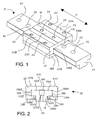
- FIGURE 1 is a perspective view of a hydrostatic linear bearing, generally indicated at 10, according to the present invention.
- the bearing 10 is comprised of a carriage 12 that is mounted for sliding, hydrostatically supported movement along a rail 14. The direction of movement is shown by arrow M in FIGURE 1 .
- the rail 14 has a "T shaped" cross section.
- the carriage 12 has a central portion 16 and two keepers, 18A, 18B that are clamped or bolted to the central portion 16 of the carriage 12.
- the carriage 12 may be fabricated as a single-piece structure; however, the use of the two separable keepers 18A, 18B makes the carriage 12 easier to fabricate, and, in particular, easier to finish grind. If the carriage 12 is fabricated as a single-piece structure, special finish grinding equipment may need to be used.
- the carriage 12 also includes a number of drain grooves 106, 108A, 108B, 110A, 110B, 112A, and 112B extending substantially the entirety of the length of the carriage.
- the drain grooves 106, 108A, 108B, 110A, 110B, 112A, and 112B will be described in more detail below.
- the carriage 12 and rail 14 have rectilinear cross-sections in this embodiment of the invention.
- rectilinear refers to any shape comprised of line segments without substantial curvature between adjacent segments.
- rectilinear cross sectional shapes are generally preferred because they are easier to machine, the carriage and rail of a hydrostatic bearing according to the invention may have any desired cross sectional shape. More generally, the carriage 12 may be shaped to engage a rail of substantially any cross-sectional shape.
- the rail 14 includes drilled and counterbored holes 20 that are used to secure it to a machine tool bed or other rigid structure.
- the carriage 12 includes drilled and tapped holes 22 such that raised surfaces 24A, 24B, 24C may be clamped rigidly to the mating surface of a machine tool table or other structure that requires linear motion guidance. (The use of the hydrostatic bearing 10 will be described in more detail below.)
- the overall size and shape of the carriage 12 and rail 14, and the locations of the holes 20, 22 in the rail and carriage may be selected so as to be "bolt-for-bolt" compatible with and of the same size as standard rolling element linear bearings. It is advantageous if this type of compatible configuration is used, because a hydrostatic bearing 10 according to the invention may then be directly substituted for a rolling element-type linear bearing in an existing machine tool or tool design.
- FIGURE 2 is a side elevational view of the carriage 12.
- the carriage 12 is hydrostatically supported by a number of bearing pads provided in interior surfaces of the carriage 12.
- the locations of the vertical bearing pads 26A, 26B, 28A, 28B and the horizontal bearing pads 30A, 30B are also shown in the perspective views of FIGURES 13-15 and will be described in more detail below with respect to those figures..
- Fluid pressure exerted through the bearing pads 26A, 26B, 28A, 28B maintains the bearing carriage 12 at a small distance from the bearing rail 14.
- the clearance between the bearing pads 26A, 26B, 28A, 28B, 30A, 30B and the rail 14 would be on the order of about 0.001 inches to about 0.005 inches (0,025-0,127 mm).
- fluid and “hydrostatic fluid” are used interchangeably to refer to any fluid that may be used in a bearing 10 according to the present invention.
- fluids are known in the art, including hydrocarbon-based oils, silicone-based oils, water, water-based compositions, and air or another suitable gas.
- hydrocarbon-based oils may be preferred for some applications. These oils tend to reduce or eliminate corrosion problems, and may also have relatively high viscosities, which help to reduce the bearing flow rate and associated pumping power needed to pressurize the bearing 10.
- Water-based hydrostatic fluids also have certain advantages and may also serve in hydrostatic bearings 10 according to the invention.
- One advantage of water-based hydrostatic fluid is that if machining coolant (typically a water-based composition) leaks into or mixes with the hydrostatic fluid, it may not present a serious contamination problem.
- Water-based hydrostatic fluids may also be used in bearings 10 that are produced for the food industry, because of the reduced risk of contaminating the consumable product. Additionally, water-based fluids generally have high thermal conductivities, which enables the heat generated by the pumping process to be removed much more easily.
- FIGURE 3 is a schematic diagram of the vertical pads 26A and 28A, showing their basic geometry and illustrating the route fluid takes through the bearing pads 26A, 28A.
- Vertical bearing pad 26B is similar in design to pad 26A and is therefore not shown.
- Vertical bearing pad 28B is identical in design to 28A and is therefore not shown. In the following description, it is assumed that the fluid path is the same in the non-illustrated bearing pads 26B, 28B. However, as those of ordinary skill in the art will realize, the design of the various vertical bearing pads 26A, 26B, 28A, 28B need not be identical.
- a lubricating fluid is pressurized and supplied by pump 32 to the upper and lower bearing pads 26A and 28A.
- the fluid enters the lower pad 28A at supply groove 34 which has a depth sufficient to allow free flow of fluid within it.
- Some fluid crosses leakage lands 36A and 36B, which are at a tight gap distance from rail 14, and exits bearing pad 28A.
- Some fluid crosses land 38 and enters pocket groove 40.
- Some fluid also crosses compensating land 42 which is at a small distance from the rail 14; this tight gap creates a pressure drop as the fluid enters compensator groove 44.
- Some fluid leaks from compensator groove 44 across lands 46A and 46B and exits bearing pad 26A.
- Some fluid is routed from compensator groove 44 to pocket groove 48 of bearing pad 26A. Some fluid leaks out of pocket groove 48 across lands 50A, 50B, and 50C where it exits bearing pad 26A. Fluid is free to flow in the tight gap region between rail 14, and central bearing pad 52, at a pressure that is equal to the fluid pressure in pocket groove 48. Fluid is also supplied at supply pressure from pump 32 to the supply grooves 54A and 54B of pad 26A. Some fluid leaks across lands 56A, 56B, 56C, and 56D and exits the bearing pad 26A. Some fluid crosses from supply grooves 54A and 54B across lands 58A and 58B to pocket groove 48.
- Some fluid crosses from supply grooves 54A and 54B across compensator lands 60A and 60B to compensator groove 62. Some fluid leaks from compensator groove 62, crosses land 64 and exits bearing pad 26A. Some fluid is routed from compensator groove 62 to bearing pad 28A where it enters pocket groove 40. Some fluid then flows from pocket groove 40 across lands 66A, 66B, and 66C where it exits bearing pad 28A. Fluid can flow between compensator groove 44 and pocket groove 40 but is largely restricted from doing so by land 68. Fluid can flow between compensator groove 62 and pocket groove 48 but is largely restricted from doing so by land 70.
- Grooves 54A, 54B, 62, 48, 34, 44, and 40 all should have a depth that is at least about three times larger than the clearance between the pads 28A and 26A and the rail 14 to ensure uniform pressure within each of these grooves. In the case of grooves 48 and 40, uniform pressure is desired to spread the load-supporting pressure over the entire pocket area. In the case of grooves 54A, 54B, 62, 34, and 44, uniform pressure is desired in order to yield the proper hydraulic resistance on the adjacent lands so that the pressure in the respective bearing areas can be adequately controlled.
- Pad 26A should be fabricated such that lands 52, 50A, 50B, 50C, 60A, 60B, 56A, 56B, 56C, 56D, 64, 58A, 58B, and 70 are preferably all on the same plane and at the same tight gap distance to rail 14.
- Pad 28A should be fabricated such that lands 66A, 66B, 66C, 42, 46A, 46B, 36A, 36B, 38, and 68 are preferably all on the same plane and at the same tight gap distance to rail 14.
- FIGURE 4 is a fluid circuit diagram of the vertical bearing pads 26A and 28A (which are identical to the counterpart vertical bearing pads 26B and 28B).
- the various lands described above with respect to FIGURE 3 are shown in FIGURE 4 as circuit resistors.
- the values of the land resistances which can be calculated by those skilled in the art of fluid dynamics, is dependent upon the fluid viscosity, the length and width of the lands, and the clearance between each land and the rail 14.
- the fluid circuit shown in FIGURE 4 can be solved by those skilled in the art of circuit analysis to compute the pressure in each of the bearing grooves. These pressures may then be multiplied by the corresponding bearing areas to yield the overall vertical force developed by the bearing.
- the bearing pad geometries may be chosen to suit particular applications of the hydrostatic bearing 10, it is preferable if the the bearing groove and land geometry are optimized to provide very high bearing stiffness and load capacity in the vertical direction with the minimum possible flow rate of fluid through the bearing 10 because high fluid flow rates typically require great amounts of pumping power.
- Grooves 54A, 54B, 62, 48, 34, 44, and 40 are shown in FIGURE 3 with rounded corners; however, they may be fabricated with sharp square corners or another geometric profile without considerable effect on bearing operation, since the hydraulic resistances of the adjacent lands will change by a very small percentage of their overall resistance values.
- fluid is routed between pad 28A and pad 26A in two places, from compensator groove 44 to pocket groove 48, and from compensator groove 62 to pocket groove 40.
- These fluid transfers may be accomplished by the use of drilled holes in carriage 12 and keeper 18A, or they may be accomplished with the use of rigid tubing external to carriage 12.
- fluid may be routed at supply pressure from pump 32 to supply grooves 34, 54A, and 54B with the use of external tubing followed by holes drilled in carriage 12 and keeper 18A.
- FIGURE 5 is a schematic view of the horizontal bearing pads 30A and 30B, showing their basic geometry and illustrating the route that fluid takes through the bearing pads 30A, 30B.
- a lubricating fluid is pressurized and supplied by pump 32 to the upper and lower bearing pads 30A and 30B.
- the same pump 32 may be used to supply the horizontal bearing pads 30A, 30B and the vertical bearing pads 26A, 26B, 28A, 28B, or two different pumps 32 may be used.
- the fluid enters pad 30A at supply groove 72A which is at a depth sufficient to allow free flow of fluid within it. Some fluid leaks from supply groove 72A across leakage lands 74A and 76A, which are at a tight gap distance from rail 14, and exits bearing pad 30A.
- the fluid in the tight clearance of bearing pad 98BA will be at a pressure equal to the fluid pressure in pocket groove 82BA because pocket groove 82BA completely surrounds bearing pad 98BA.
- Fluid is also supplied at supply pressure from pump 32 to supply groove 72B of bearing pad 30B. Some of the fluid which enters supply groove 72B leaks across lands 74B and 76B and exits bearing pad 30B. Some of the fluid which enters supply groove 72B leaks across lands 78BA and 80BA to pocket groove 82BA, and some leaks across lands 78BB and 80BB to pocket groove 82BB. Some of the fluid which enters supply groove 72B leaks across compensator lands 84BA, 86BA, and 88BA to compensator groove 90BA.
- Some fluid may across land 100BA between compensator groove 90BA and pocket groove 82BA.
- the remainder of fluid entering compensator groove 90BA is routed to pad 30A where it enters pocket grooves 82AA and leaks across lands 92AA, 94AA, and 96AA and exits bearing pad 30A.
- the fluid in the tight gap clearance of bearing pad 98AA will be at a pressure equal to the fluid pressure in pocket groove 82AA because pocket groove 82AA completely surrounds bearing pad 98AA.
- Some of the fluid which enters supply groove 72A leaks across compensator lands 84AB, 86AB, and 88AB to compensator groove 90AB.
- Some fluid may across land 100AB between compensator groove 90AB and pocket groove 82AB.
- the remainder of fluid entering compensator groove 90AB is routed to pad 30B where it enters pocket groove 82BB and leaks across lands 92BB, 94BB, and 96BB and exits bearing pad 30B.
- the fluid in the tight gap clearance of bearing pad 98BB will be at a pressure equal to the fluid pressure in pocket groove 82BB because pocket groove 82BB completely surrounds bearing pad 98BB.
- Some of the fluid which enters supply groove 72B leaks across compensator lands 84BB, 86BB, and 88BB to compensator groove 90BB.
- Some fluid may across land 100BB between compensator groove 90BB and pocket groove 82BB.
- Grooves 82AA, 82AB, 82BA, 82BB, 90AA, 90AB, 90BA, 90BB, 72A, and 72B all should have a depth that is at least three times larger than the clearance between the pads 30A and 30B and the rail 14 to ensure uniform pressure within each of these grooves.
- uniform pressure is desired in order to spread the load-supporting pressure over the entire pocket area.
- uniform pressure is desired in order to yield the proper hydraulic resistance on the adjacent lands so that the pressure in the respective bearing areas can be adequately controlled.
- Pad 30A is fabricated such that lands 98AA, 98AB, 84AA, 84AB, 86AA, 86AB, 88AA, 88AB, 92AA, 92AB, 94AA, 94AB, 96AA, 96AB, 78AA, 78AB, 80AA, 80AB, 100AA, 100AB, 74AA, 74AB, 76AA, 76AB are preferably all on the same plane and at the same tight gap distance to rail 14.
- Pad 30B should be fabricated such that lands 98BA, 98BB, 84BA, 84BB, 86BA, 86BB, 88BA, 88BB, 92BA, 92BB, 94BA, 94BB, 96BA, 96BB, 78BA, 78BB, 80BA, 80BB, 100BA, 100BB, 74BA, 74BB, 76BA, 76BB are preferably all on the same plane and at the same tight gap distance to rail 14.
- FIGURE 6 is a schematic diagram showing the fluid resistances of the horizontal bearing pad 30A. Each of the resistances shown in FIGURE 6 represents one of the lands of the horizontal bearing pad 5A. The values of the resistances of the horizontal bearing pad 30A may be calculated as was described above with respect to the vertical bearing pads 26A, 26B, 28A, 28B.
- Grooves 82AA, 82AB, 82BA, 82BB, 90AA, 90AB, 90BA, 90BB, 72A, and 72B are shown in FIGURE 5 with rounded comers; however, they may be fabricated with sharp square corners or another geometric profile without considerable effect on bearing operation since the hydraulic resistances of the adjacent lands will change by a very small percentage of their overall resistance values.
- fluid is routed between pad 30A and pad 30B in four places: from compensator groove 90AB to pocket groove 82BB, from compensator groove 90AA to pocket groove 82BA, from compensator groove 90BA to pocket groove 82AA, and from compensator groove 90BB to pocket groove 82AB.
- these fluid transfers may be accomplished by the use of drilled holes in carriage 12, or they may be accomplished with the use of rigid tubing external to carriage 12.
- fluid may be routed at supply pressure from pump 32 to supply grooves 72A and 72B with the use of external tubing followed by holes drilled in carriage 12.
- lands 58A, 58B, 70, 38, 68, 78AA, 78AB, 78BA, 78BB, 80AA, 80AB, 80BA, 80BB, 100AA, 100AB, 100BA, and 100BB allow leakage paths between adjacent compensators, pockets, and supply grooves. These leakage paths tend to reduce the pressure response of the bearing and therefore reduce its stiffness and load-carrying capability.
- pocket grooves 48, 40, 82AA, 82AB, 82BA, and 82BB are closer to the compensating grooves, and, therefore, spread the load-supporting pocket pressures over a larger area.
- the bearing pad configurations of the hydrostatic bearing 10 provide higher stiffness and load capacity.
- FIGURE 7 is another perspective view of the hydrostatic bearing of FIGURE 1 , with its seals and endcaps installed.
- FIGURE 8 is a sectional view through Line 8-8 of FIGURE 7, and
- FIGURE 9 is a close-up view of portion A (enclosed in dotted line) of FIGURE 8.
- FIGURES 7-9 show the hydrostatic bearing of FIGURE 1 with end caps 102A and 102B attached to carriage 12 and keepers 18A and 18B.
- End caps 102A and 102B contain reservoirs 104A and 104B (visible in the views of FIGURES 8 and 9 ) to which the fluid flows into from bearing pads 26A, 26B, 28A, 28B, 30A, and 30B as well as from drain grooves 106, 108A, 108B, 110A, 110B, 112A, and 112B. (As was described above, the drain grooves are provided at the corners of the carriage 12 and are visible in the views of FIGURES 1 and 2 .) Double-lipped end seals 114A and 114B are attached to end caps 102A and 102B.
- the double-lipped end seals 114A, 114B are attached to rigid plates 113A, 113B in order to provide them with additional stiffness. Lips 116 of end seals 114A and 114B are in sliding engagement with rail 14 and serve to trap the fluid into reservoirs 104A and 104B and largely prevent fluid from leaking directly out of the hydrostatic bearing 10.
- the fluid flows out of reservoirs 104A or 104B through at least one drain outlet 118A and/or 118B.
- One or more of the drain outlets 118A, 118B may be plugged, but at least one drain outlet 118A, 118B is used to route the fluid to a hose or tubing assembly, where the fluid is returned to the hydraulic supply source.
- FIGURE 10 is a sectional side elevational view of the hydrostatic bearing 10, illustrating side seals 120A and 120B that are received by acceptor grooves 122A and 122B within keeper portions 18A and 18B of the bearing carriage 12.
- FIGURE 11 is an enlarged sectional view of portion B of FIGURE 10 , illustrating the side seal 120B in more detail.
- the side seals 120A, 120B slidingly engage the bearing rail 14, serve to trap fluid, and allow the trapped fluid to be routed through drain grooves 112A and 112B into reservoirs 104A and 104B to prevent fluid from leaking directly out of the hydrostatic bearing 10.
- the side seal 120B has a generally u-shaped portion 121 that opens upwardly, towards the top of the drain groove 112B.
- the side seals 120A, 120B are positioned in the acceptor groove 122A, 122B such that one wall of the u-shaped portion 121 of the side seal 120A, 120B is in contact with the keeper 18A, 18B and the other wall of the u-shaped portion 121 is in contact with the bearing rail 14.
- FIGURE 13 is a perspective view of the underside of the central portion 16 of the carriage 12 without the keepers 18A, 18B installed.
- FIGURE 13 shows the relative locations and extents of the vertical bearing pads 26A, 26B and the horizontal bearing pads 30A, 30B.
- FIGURES 14 and 15 are perspective views of the keepers 18A and 18B, showing the locations and extents of vertical bearing pads 28A and 28B on the keepers 18A and 18B. The positions of the drain grooves 106, 108A, 108B, 110A, 110B, 112A, and 112B and seal acceptor grooves 122A, 122B are also shown.
- Each side of the central portion 16 of the bearing carriage 12 has a set of threaded holes 222 provided in respective connecting surfaces 220A and 220B.
- a set of complimentary, counterbored through holes 226 are provided in the keepers 18A and 18B.
- bearing pad grooves and other surface features shown in FIGURES 13-15 may be formed by milling, electrical discharge machining, or other known techniques.
- FIGURE 16 is a perspective view showing the end seals 114A, 114B and side seals 120A, 120B in isolation.
- the end seals 114A, 114B are constructed of a rubber material molded so as to attach to rigid plates 113A, 113B, for example, steel or aluminum plates, to provide them with greater rigidity.
- the end seals 114A, 114B may not be attached to rigid plates 113A, 113B
- the side seal 120B is inserted into receptacle 115 formed in the end seal 114B such that it has an interference fit with the receptacle 115.
- the side seals 120A, 120B may be made slightly longer than required, such that they can be maintained in compression during operation.
- the side seals 120A, 120B and the end seals 114A, 114B may be molded or cast as a single structure, bonded together, or otherwise caused to adhere to one another to form a unitary structure.
- bearing pads 26A, 26B, 28A, 28B, 30A, 30B described above are designed for a self-compensating hydrostatic bearing.
- those of ordinary skill in the art will realize that the other features of the carriage 12 and rail 14, including the sealing structures (i.e., the end seals 114A, 114B and side seals 120A, 120B) and the drain grooves 106, 108A, 108B, 110A, 110B, 112A, and 112B may be used without the particular bearing pads 26A, 26B, 28A, 28B, 30A, 30B described above.
- a carriage having end seals, side seals and a drain groove arrangement similar to that described above could be used with bearing pads that are not self-compensating.
- Bearing pads that are not self-compensating could use capillary tubes or valves for compensation purposes, as one of ordinary skill in the art will readily be able to appreciate.
- self-compensating bearing pads 26A, 26B, 28A, 28B, 30A, 30B described above may be used on other types of hydrostatically supported devices and in other types of fluidstatic bearings without the other features described herein.
- FIGURE 18 is a schematic perspective view illustrating four bearing carriages 12 riding on two carriage rails 14.
- several bearing carriages 12 may be provided on the same carriage rail 14, particularly if those bearing carriages 12 are fixed in position with respect to one another (e.g., by being bolted to the bed of a machine tool, as will be described below).
- several shorter segments of bearing rail 14 could be provided, one segment for each bearing carriage 12.
- FIGURE 18 also illustrates the details of the hydraulic fluid connections for the bearings 10 according to the present invention.
- a hydraulic power unit 230 delivers hydraulic fluid under high pressure through a conduit 232.
- the hydraulic power unit 230 includes all of the components necessary to deliver temperature controlled fluid that is relatively free of contaminant particles at high pressure with minimal pressure pulsations.
- the hydraulic power unit 230 may include a reservoir, a pump, an electric motor, a filter, a pressure regulating valve, a pressure gauge, and a heat rejection system, such as an air-to-oil heat exchanger.
- the conduit 232 from the hydraulic power unit 230 branches such that one branch connects with each bearing carriage 12.
- the branches of the conduit 232 are received by a fluid inlets 119 in the end seals 114A, 114B of the bearing carriages 12.
- the conduit 232 may connect to a fluid inlet 119 on either end seal 114A, 114B.
- the unused fluid inlet 119 may be plugged or omitted.
- the connection between the conduit 232 branch and the fluid inlet 119 of the end seal may be any appropriate type of conventional hydraulic connection.
- the pressurized fluid is distributed to the supply grooves 34, 54A, 54B by an internal network of passageways. Once used, the fluid is collected in the reservoirs 104A, 104B and returned via return conduits 238, which connect to the drain outlets 118A, 118B and the return portions of the hydraulic power unit 232.
- FIGURE 12 is a side elevational view of a machine tool 200, illustrating a typical application for a hydrostatic bearing 10 according to the present invention.
- a machine tool table 202 is supported by four bearing assemblies 10 which ride on two rails 14. Although only two bearing assemblies 10 are shown, at least four are typically used to provide adequate pitch and yaw stability to table 202.
- the rails 14 of the hydrostatic bearings 10 are horizontally clamped to a machine bed 204 using wedges 206A and 206B.
- the rails 14 are clamped vertically to machine bed 204 using a plurality of bolts 208 threadedly secured within machine bed 204 through counterbored holes 20 provided in the rail 14.
- FIGURE 12 illustrates the use of wedges 206A, 206B, and 210, many other mechanisms to clamp the rails 14 and the hydrostatic bearings 10 are possible and are within the scope of the invention.
- a hydrostatic bearing 10 may be used in a number of different types of machine tools, and in any other application in which linear motion guidance is required.
- hydrostatic bearings 10 according to the invention may be particularly beneficial when used in lathes.
- hydrostatic bearings 10 may be used in the QUEST ® turning machines manufactured by HARDINGE, Inc. (Elmira, NY, United States).
- Hydrostatic bearings 10 may also be useful in grinding machines, milling machines, boring machines, and other machine tools in which a combination of high stiffness and damping are beneficial.
- a hydrostatic bearing 10 according to the present invention may have certain advantageous performance characteristics.
- a hydrostatic bearing 10 according to the invention would typically have high static and dynamic stiffnesses.
- a hydrostatic bearing 10 may also operate with very low friction, because the seals described above with respect to FIGURES 7-11 would generally be the only components creating friction. Because the carriage 12 rides on a layer of fluid, and for other reasons, the hydrostatic bearing 10 may have up to ten times the force damping capabilities of a conventional rolling element linear bearing.
- Additional advantages may include an essentially unlimited translational (feed) rate, an essentially unlimited fatigue life (with substantially no component wear because the carriage 12 and rail 14 are not in contact), substantially no change in positioning accuracy of a machine tool mounted on hydrostatic bearings 10 over time, substantially no damage to the hydrostatic bearing 10 under heavy "crash” loads (i.e., when the bearing 10 stops suddenly at the ends of its travel range).
- the hydrostatic bearing 10 is self cleaning if fluid flow is maintained between the carriage 12 and rail continuously 14.
- the features of the hydrostatic bearing 10 may also lead to certain other advantages.
- the hydrostatic bearing 10 may improve tool life.
- parts may be produced with better surface finishes and better roundnesses for round parts.
- a machine tool mounted on hydrostatic bearings 10 may also have improved hard turning capability, improved interrupted cutting capability, and improved positioning accuracy.
- a hydrostatic bearing 10 according to the invention is installed so as to support operational movement in a QUEST ® 51 turning machine (Hardinge, Inc., Elmira, NY, United States) using the installation procedure described above.
- QUEST ® 51 turning machine Hardinge, Inc., Elmira, NY, United States
- Four hydrostatic bearings 10 according to the present invention are installed to guide motion in the X-axis and four are installed to guide motion in the Z-axis. No adaptations to the turning machine are required in order to accommodate the hydrostatic bearings 10; however, hydraulic hoses are provided for each hydrostatic bearing 10.
- a two-inch round A2 tool steel blank was prepared with four slots milled around its circumference for interrupted cutting. It was then hardened to 60-62 Rc.
- the part was then roughed with a 5/16 inch diameter round cubic boron nitride (CBN) insert at 450 SFM/0.002 ipr/0.030 doc with five passes. Subsequently, the part was finished with a 55 degree CBN insert at 550 SFM/0.003 ipr/0.005 doc with one pass, and then threaded with a CBN triangular insert.
- CBN cubic boron nitride
- the surface finish of the part was consistently in the 5 to 6 microinch range, an improvement of approximately a factor of two when compared with an identical part machined on a comparable QUEST ® 51 turning machine without a hydrostatic bearing. Additionally, the tool life of the interrupted turning insert was increased by a factor of three when compared to the life of an insert used on the turning machine without the hydrostatic bearing.
Landscapes
- Engineering & Computer Science (AREA)
- General Engineering & Computer Science (AREA)
- Mechanical Engineering (AREA)
- Magnetic Bearings And Hydrostatic Bearings (AREA)
- Bearings For Parts Moving Linearly (AREA)
- Sliding-Contact Bearings (AREA)
- Machine Tool Units (AREA)
Claims (29)
- Hydrostatisches Lager, umfassend:eine Lagerschiene (14); undeinen Lagerschlitten (12), der so ausgestaltet und angeordnet ist, dass er für eine hydrostatisch gestützte Bewegung auf der Lagerschiene montiert werden kann, wobei der Lagerschlitten einschließt:eines bzw. mehrere Lagerkissen (26, 28, 30), die auf der Lagerschiene gegenüber liegenden Flächen vorgesehen sind, wobei das bzw. die Lagerkissen so ausgestaltet und angeordnet sind, dass sie in Fluid-Verbindung mit der unter Druck stehenden Fluid-Quelle stehen; gekennzeichnet durch eine aneinandergrenzende Seiten- und Endabschnitte (120, 114) aufweisende Dichtungsstruktur (102);ein Fluid-Rückführungssystem, das eine Vielzahl an abführenden Nuten (106, 108, 110, 112) in Fluid-Verbindung mit dem bzw. den Lagerkissen beinhaltet, wobei zumindest eine abführende Nut der Vielzahl an abführenden Nuten zwischen einem bzw. mehreren Lagerkissen und der Dichtungsstruktur positioniert ist.
- Hydrostatisches Lager nach Anspruch 1, wobei der Lagerschlitten (12) weiterhin einen bzw. mehrere Speicher (104) in Fluid-Verbindung mit der Vielzahl an abführenden Nuten umfasst.
- Hydrostatisches Lager nach Anspruch 3, wobei der oder die Speicher eine Vielzahl an Speichern umfassen, die in Endabschnitten des Lagerschlittens vorgesehen sind, wobei einer der Vielzahl an Speichern Fluid-Einlass- und Auslassöffnungen einschließt, die in Verbindung mit einer hydraulischen Krafteinheit stehen.
- Hydrostatisches Lager nach einem der Ansprüche 1 bis 3, wobei die Lagerschiene eine gradlinige Gestalt aufweist.
- Hydrostatisches Lager nach einem der Ansprüche 1 bis 3, wobei die Lagerschiene eine T-förmige Querschnittsfläche aufweist.
- Hydrostatisches Lager nach einem der Ansprüche 1 bis 5, wobei das bzw. die Lagerkissen selbstkompensierende Lagerkissen sind.
- Hydrostatisches Lager nach Anspruch 1, wobei der Lagerschlitten weiterhin umfasst:eine Fluid-Einlassöffnung, die so ausgestaltet und angeordnet ist, dass sie hydraulische Fluid-Schläuche aufnehmen kann, wobei diese Fluid-Einlassöffnung in Fluid-Verbindung mit dem oder den Lagerkissen steht; undeine Fluid-Auslassöffnung, die so ausgestaltet und angeordnet ist, dass sie hydraulische Fluid-Schläuche aufnehmen kann, wobei die Fluid-Auslassöffnung in Fluid-Verbindung mit der Vielzahl an abführenden Nuten steht.
- Hydrostatisches Lager nach Anspruch 1, weiterhin umfassend ein Befestigungsloch bzw. mehrere Befestigungslöcher (22), das (die) auf Oberflächen des Lagerschlittens vorgesehen ist (sind), wobei die Befestigungslöcher so ausgestaltet und angeordnet sind, dass ein Maschinenbauteil in die Lage versetzt wird, entfernbar an dem Lagerschlitten montiert zu sein.
- Maschinenwerkzeug, das an einem bzw. mehreren hydrostatischen Lagern nach einem der Ansprüche 1 bis 8 montiert ist.
- Hydrostatisches Lager nach einem der Ansprüche 1 bis 9, wobei die Seitenabschnitte der Dichtungsstruktur einen im Wesentlichen nach oben weisenden U-förmigen Querschnitt aufweisen.
- Hydrostatisches Lager nach Anspruch 1, wobei der Lagerschlitten weiterhin einen zentralen Abschnitt und entfernbar montierte Halterabschnitte (18) aufweist, die in Abschnitte der Lagerschiene eingreifen.
- Hydrostatisches Lager nach Anspruch 11, wobei die Seitenabschnitte der Dichtungsstruktur innerhalb der Dichtungsnuten in den Halterabschnitten angebracht sind.
- Hydrostatisches Lager nach Anspruch 1, wobei sich zumindest eine der Vielzahl an abführenden Nuten längsseits des Lagerschlittens erstreckt.
- Hydrostatisches Lager nach Anspruch 1, wobei die Endabschnitte der Dichtungsstruktur Doppellippen-Dichtungen beinhalten.
- Hydrostatisches Lager nach Anspruch 1, wobei das eine Lagerkissen bzw. eines von mehreren Lagerkissen eine Taschennut beinhaltet, die wiederum eine erste plane Region umschließt, die so ausgestaltet und angeordnet ist, dass sie einem Strom eines unter Druck stehenden Fluids widersteht, wenn sich das eine Lagerkissen bzw. eines von mehreren Lagerkissen in einer Last tragenden Stellung relativ zu der Lagerschiene befindet; und
wobei die Vielzahl an abführenden Nuten die Taschennut vollständig umgibt. - Hydrostatisches Lager nach Anspruch 15, wobei das eine Lagerkissen bzw. eines von mehreren Lagerkissen eine zweite plane Region beinhaltet, die so ausgestaltet und angeordnet ist, dass sie einem Strom eines unter Druck stehenden Fluids widersteht, wenn sich das eine Lagerkissen oder eines von mehreren Lagerkissen in einer Last tragenden Stellung relativ zu der Lagerschiene befindet, wobei die zweite plane Region die Taschennut aneinandergrenzend umgibt, wobei die Vielzahl an abführenden Nuten die zweite plane Region vollständig umgibt.
- Hydrostatisches Lager nach Anspruch 1, wobei die Vielzahl der abführenden Nuten das bzw. die Lagerkissen vollständig umgibt.
- Hydrostatischer Lagerschlitten (12), der so ausgestaltet und angeordnet ist, dass er für eine hydrostatisch gestützte Bewegung auf einer Lagerschiene montiert wird, wobei der Lagerschlitten eine Vielzahl an selbstkompensierenden Lagerkissen umfasst, wobei die Vielzahl an Lagerkissen so ausgestaltet und angeordnet ist, dass sie in Fluid-Verbindung mit einer unter Druck stehenden Quelle (32) stehen, wobei jedes Lagerkissen umfasst:eine Kompensationsnut (44, 62) und eine Taschennut (40, 52);wobei die Taschennut fluide mit einer Kompensationsnut einer weiteren Vielzahl an Lagerkissen verbunden ist, und die Kompensationsnut fluide mit einer Taschennut einer weiteren der Vielzahl an Lagerkissen verbunden ist; eine Zuführnut (34, 54), sie so ausgestaltet und angeordnet ist, dass sie ein unter Druck stehendes Fluid aus einer unter Druck stehenden Fluid-Quelle (32) aufnehmen kann;einen Widerstandsbereich, der die Kompensations-, Taschen- und Zuführnuten umgibt, wobei der Widerstandsbereich so ausgestaltet und angeordnet ist, dass er unter Druck stehendes Fluid aus der Taschennut aufnehmen kann, um eine tragende Fluid-Schicht zwischen dem Lagerkissen und der Lagerschiene zu schaffen, wobeigekennzeichnet dadurch, dass es sich bei dem Widerstandsbereich um eine plane Fläche handelt; und dadurch, dassein Fluid-Rückströmsystem, das zumindest eine abführende Nut (106, 108, 110, 112) beinhaltet, den Widerstandsbereich vollständig umgibt; undeine Dichtungsstruktur die wenigstens eine abführende Nut vollständig umgibt.
- Hydrostatischer Lagerschlitten nach Anspruch 18, wobei die plane Fläche die Kompensationsnut, Taschennut und Zuführnut jeweils voneinander und von der bzw. den abführenden Nuten trennt,
wobei die plane Fläche die Kompensationsnut, die Taschennut und die Zuführnut umgibt,
wobei die Taschennut die Kompensationsnut bzw. die Versorgungsnut nicht umgibt;
wobei die plane Fläche keine abführende Nut beinhaltet, die die Taschennut von der Zuführnut trennt, und
wobei die Zuführnut zumindest teilweise zwischen der Kompensationsnut und der bzw. den abführenden Nut(en) eingefügt ist. - Hydrostatischer Lagerschlitten nach Anspruch 18, wobei das Fluid-Rückströmsystem weiterhin einen Fluid-Rückströmkanal in Fluid-Verbindung mit der bzw. den Nut(en) umfasst, wobei der Fluid-Rückströmkanal so ausgestaltet und angeordnet ist, dass Fluid von der bzw. den ableitenden Nut(en) an die unter Druck stehende Fluid-Quelle geleitet wird.
- Hydrostatischer Lagerschlitten nach Anspruch 18, wobei die Zuführnut das Austreten von Fluid aus der Kompensationsnut hin zu einem Außenrand der planen Fläche verhindert.
- Hydrostatischer Lagerschlitten nach Anspruch 18, wobei die Zuführnut die meisten der direkten Fluid-Austrittswege zwischen der Kompensationsnut und dem Außenrand der planen Fläche eliminiert.
- Hydrostatischer Lagerschlitten nach Anspruch 18, wobei die Zuführnut die meisten Kompensationsnuten umgibt.
- Hydrostatischer Lagerschlitten nach Anspruch 18, wobei eine Stellung der Zuführnut einen Fluid-Austrittsweg zwischen der Kompensationsnut und einem Außenrand der planen Fläche reduziert.
- Hydrostatischer Lagerschlitten nach Anspruch 18, wobei die Zuführnut zumindest teilweise zwischen der Kompensationsnut und einem Außenrand der planen Fläche eingefügt ist.
- Hydrostatischer Lagerschlitten nach Anspruch 1, wobei:das eine bzw. die Lagerkissen erste und zweite Lagerkissen, die so ausgestaltet und angeordnet, dass sie Fluid aus der unter Druck stehenden Fluid-Quelle aufnehmen können, wobei das erste und das zweite Lagerkissen erste bzw. zweite plane Flächen umfassen, und erste bzw. zweite Lagernuten in den ersten bzw. zweiten Flächen umfassen, um zu bewerkstelligen, dass Fluid selektiv über die Lagernuten und planen Flächen strömt, um eine tragende Fluid-Schicht zwischen dem Lagerschlitten und der Lagerschiene zu schaffen,wobei die Vielzahl der abführenden Nuten das erste und das zweite Lagerkissen umgeben,die Dichtungsstruktur die Vielzahl der abführenden Nuten umgibt,die Dichtungsstruktur nicht zum Bilden eines vollständigen Rings um die Schiene ausgestaltet und angeordnet ist, unddie erste plane Fläche mit der zweiten planen Fläche nicht koplanar ist.
- Hydrostatisches Lagerkissen, umfassend:eine Kompensationsnut;eine benachbarte Taschennut, die wiederum eine erste plane Region umschließt, die so ausgestaltet und angeordnet ist, dass sie einem Strom von unter Druck stehendem Fluid widersteht, wenn sich das hydrostatische Lagerkissen in einer Last tragenden Stellung relativ zu einer weiteren Fläche befindet;eine zweite plane Region, die zwischen der Kompensationsnut und der Taschennut eingefügt ist, die so ausgestaltet und angeordnet ist, dass sie dem Strom des unter Druck stehenden Fluids aus der Kompensationsnut hin zu der benachbarten Taschennut widersteht, wenn sich das Lagerkissen in der Last tragenden Stellung relativ zu der weiteren Fläche befindet;eine Zuführnut nahe der Kompensationsnut, wobei die Zuführnut und die Kompensationsnut durch eine dritte plane Region getrennt sind, die so ausgestaltet und angeordnet ist, dass sie einem Strom von unter Druck stehendem Fluid aus der Zuführnut hin zu der Kompensationsnut widersteht;eine bzw. mehrere abführende Nut(en), die die Kompensationsnut, die Taschennut und die Zuführnut vollständig umgibt(umgeben); undeine Dichtungsstruktur, die die eine bzw. mehrere Abführnut(en) vollständig umgibt(umgeben),wobei die Zuführnut in ihrer Gesamtheit auf einer planen Fläche des Lagerkissens angebracht ist.
- Hydrostatisches Lagerkissen nach Anspruch 27, wobei die zweite plane Region keine Nuten zwischen der Kompensationsnut und der Taschennut beinhaltet.
- Hydrostatisches Lagerkissen nach Anspruch 27, wobei:die Taschennut die Kompensationsnut bzw. die Zuführnut nicht umgibt,die zweite plane Region keine ableitende Nut beinhaltet, die die Taschennut von der Zuführnut trennt, unddie Zuführnut zumindest teilweise zwischen der Kompensationsnut und der bzw. den abführenden Nut(en) eingefügt ist.
Applications Claiming Priority (5)
| Application Number | Priority Date | Filing Date | Title |
|---|---|---|---|
| US40693302P | 2002-08-30 | 2002-08-30 | |
| US406933P | 2002-08-30 | ||
| US10/617,390 US20040042689A1 (en) | 2002-08-30 | 2003-07-11 | Hydrostatic bearing for linear motion guidance |
| US617390 | 2003-07-11 | ||
| PCT/US2003/026816 WO2004020852A1 (en) | 2002-08-30 | 2003-08-28 | Hydrostatic bearing for linear motion guidance |
Publications (2)
| Publication Number | Publication Date |
|---|---|
| EP1534969A1 EP1534969A1 (de) | 2005-06-01 |
| EP1534969B1 true EP1534969B1 (de) | 2009-07-01 |
Family
ID=31981450
Family Applications (1)
| Application Number | Title | Priority Date | Filing Date |
|---|---|---|---|
| EP03749158A Expired - Lifetime EP1534969B1 (de) | 2002-08-30 | 2003-08-28 | Hydrostatisches lager für linearführung |
Country Status (12)
| Country | Link |
|---|---|
| US (3) | US20040042689A1 (de) |
| EP (1) | EP1534969B1 (de) |
| JP (1) | JP2005537446A (de) |
| KR (1) | KR100989668B1 (de) |
| CN (1) | CN100400908C (de) |
| AT (1) | ATE435374T1 (de) |
| AU (1) | AU2003268207A1 (de) |
| BR (1) | BR0313956A (de) |
| CA (1) | CA2496915A1 (de) |
| DE (1) | DE60328200D1 (de) |
| ES (1) | ES2329671T3 (de) |
| WO (1) | WO2004020852A1 (de) |
Families Citing this family (52)
| Publication number | Priority date | Publication date | Assignee | Title |
|---|---|---|---|---|
| US6909581B2 (en) * | 2003-05-02 | 2005-06-21 | Segway Systems, Llc | Tape head assembly with air bearing guide |
| JP2005344801A (ja) * | 2004-06-02 | 2005-12-15 | Fanuc Ltd | 制動装置 |
| DE102005023998A1 (de) * | 2005-05-25 | 2006-12-14 | Schaeffler Kg | Hydrostatische Lagerung |
| DE102005038341A1 (de) | 2005-08-13 | 2007-02-15 | Schaeffler Kg | Hydrostatische Profilschienenführung |
| EP1800799A1 (de) * | 2005-12-22 | 2007-06-27 | Aktiebolaget SKF | Vibrationsgerät für eine Feinziehschleifmaschine und Vorsatzgerät mit einem solchen Vibrationsgerät |
| KR100650563B1 (ko) * | 2005-12-27 | 2006-11-30 | 주식회사 포스코 | 쌍롤식 연속박판 주조공정의 주조롤 무빙장치 |
| DE102006014446A1 (de) * | 2006-03-29 | 2007-10-04 | Schaeffler Kg | Stromregelventil |
| US7624907B2 (en) * | 2007-06-15 | 2009-12-01 | Cyril Bath Company | Linear friction welding apparatus and method |
| DE102007030883A1 (de) | 2007-07-03 | 2009-01-08 | Schaeffler Kg | Dichtung für eine hydrostatische Linearführung |
| TWI411481B (zh) | 2007-10-30 | 2013-10-11 | Toshiba Machine Co Ltd | 精密軋輥車床 |
| WO2009077871A2 (en) * | 2007-10-31 | 2009-06-25 | Corts Engineering Gmbh | Linear bearing plate for rolling mill |
| WO2009077872A2 (en) * | 2007-10-31 | 2009-06-25 | Corts Engineering Gmbh | Lubrication delivery system for linear bearings |
| DE102008047298A1 (de) | 2008-09-16 | 2010-04-15 | Schaeffler Kg | Hydrostatische Profilschienenführung |
| DE102008047297A1 (de) | 2008-09-16 | 2010-04-15 | Schaeffler Kg | Hydrostatische Lagerung |
| DE102008047299A1 (de) | 2008-09-16 | 2010-04-15 | Schaeffler Kg | Hydrostatische Lagerung |
| CN101769336B (zh) * | 2009-01-05 | 2013-02-13 | 鸿富锦精密工业(深圳)有限公司 | 空气导轨 |
| TWI421416B (zh) * | 2009-10-30 | 2014-01-01 | Ind Tech Res Inst | 線性滑台 |
| JP4992986B2 (ja) * | 2010-01-22 | 2012-08-08 | 新東工業株式会社 | 静圧軸受装置および静圧軸受装置を備えたステージ |
| RU2605027C2 (ru) * | 2010-07-26 | 2016-12-20 | Кортс Инжиниринг Гмбх Унд Ко. Кг | Выравнивающаяся текучей средой опорная плита |
| TWI407023B (zh) * | 2010-12-03 | 2013-09-01 | Ind Tech Res Inst | 自動補償液靜壓軸頸軸承 |
| US20120213457A1 (en) * | 2011-02-22 | 2012-08-23 | Pacific Bearing Company | Linear Guide Unit |
| CN102943812B (zh) * | 2011-08-15 | 2015-03-04 | 宋震国 | 主动补偿式液静压轴承及使用其的液静压轴承模块 |
| TWI516336B (zh) | 2012-10-23 | 2016-01-11 | 財團法人工業技術研究院 | 液靜壓工作裝置 |
| CN102996635B (zh) * | 2012-10-30 | 2016-06-08 | 无锡鸿声铝业有限公司 | 一种双弯单矫机组的导轨组件 |
| CN103410859B (zh) * | 2012-12-18 | 2017-07-14 | 芜湖陀曼精机科技有限公司 | 一种定压式静压导轨节流器 |
| CN103410860A (zh) * | 2012-12-18 | 2013-11-27 | 芜湖陀曼精机科技有限公司 | 一种滑块式静压导轨组合密封装置 |
| CN104100636A (zh) * | 2013-04-01 | 2014-10-15 | 上海意丰机电科技开发有限公司 | 带保压环的滑动轴承 |
| JP6274602B2 (ja) * | 2014-02-28 | 2018-02-07 | 日立工機株式会社 | 卓上切断機 |
| CN103899646B (zh) * | 2014-03-25 | 2016-04-20 | 西安理工大学 | 带磁流变液阻尼器的液体静压导轨 |
| CN104295605A (zh) * | 2014-09-23 | 2015-01-21 | 哈尔滨工程大学 | 环带复合节流静压气体球面轴承 |
| CN105537970B (zh) * | 2014-10-28 | 2018-07-27 | 东芝机械株式会社 | 机床的引导机构以及机床 |
| JP6559937B2 (ja) * | 2014-10-28 | 2019-08-14 | 東芝機械株式会社 | 油静圧案内機構および工作機械 |
| CN104500569A (zh) * | 2014-12-23 | 2015-04-08 | 天津尚吉液压设备有限公司 | 一种单约束自由度的t型液压轴承 |
| CA2979254C (en) | 2015-03-30 | 2023-10-24 | Hicor Technologies, Inc. | Compressor with liquid injection cooling |
| US10077806B2 (en) | 2015-07-15 | 2018-09-18 | National Tsing Hua University | Compact bearing system and machine stage system equipping the same |
| DE102015122675A1 (de) * | 2015-12-23 | 2017-06-29 | Airbus Operations Gmbh | Sicherungsvorrichtung und Linearführungsmechanismus |
| CN108463297B (zh) * | 2016-01-12 | 2020-10-23 | 斯多里机械有限责任公司 | 用于制罐机的外侧流体静力学支承组件 |
| US10550886B2 (en) * | 2016-07-14 | 2020-02-04 | Cascade Corporation | Nonmetallic bearing on bearing assembly |
| CN107138778B (zh) * | 2017-06-27 | 2019-04-26 | 南昌与德通讯技术有限公司 | 侧孔倒角加工方法 |
| JP6934526B2 (ja) * | 2017-09-15 | 2021-09-15 | 株式会社牧野フライス製作所 | 移動体の案内装置 |
| CN108071677B (zh) * | 2018-01-31 | 2024-02-27 | 江苏工大金凯高端装备制造有限公司 | 一种气浮导轨 |
| US10451109B1 (en) * | 2018-04-18 | 2019-10-22 | Schaeffler Technologies AG & Co. KG | Linear guide bearing and associated quick-change system |
| CN108468148B (zh) * | 2018-05-25 | 2023-12-19 | 浙江智乙机械有限公司 | 一种智控提花手套机 |
| CN108532113B (zh) * | 2018-05-25 | 2023-12-19 | 浙江智乙机械有限公司 | 一种智控提花手套机的机头 |
| US10704598B1 (en) * | 2019-03-05 | 2020-07-07 | Hiwin Technologies Corp. | Hydrostatic linear guideway |
| NL2023326B1 (nl) * | 2019-06-17 | 2021-01-27 | De Wiel Services B V | Dwarssupport voor een freesmachine |
| NL2023329B1 (nl) * | 2019-06-17 | 2021-01-27 | De Wiel Services B V | Freesinrichting met variabele positionering van een freesmachine |
| WO2021112759A1 (en) * | 2019-12-07 | 2021-06-10 | Akribis Systems Pte. Ltd. | Ultra-low profile aerostatic bearing and the method of manufacturing the same |
| CN111043153A (zh) * | 2019-12-25 | 2020-04-21 | 嘉善万润精密机械股份有限公司 | 组合滑块及其封边结构 |
| CN115178987A (zh) * | 2022-06-21 | 2022-10-14 | 无锡威孚奥特凯姆精密机械有限公司 | 一种基于硬车加工工艺的工件密封面加工方法 |
| CN115289376B (zh) * | 2022-07-22 | 2025-06-24 | 广东佛斯伯智能设备有限公司 | 一种导轨滑块自动加油方法及导轨滑块自动加油结构 |
| CN116877573B (zh) * | 2023-06-25 | 2025-10-31 | 咸阳丰宁机械有限公司 | 一种提高承载能力的直线导轨 |
Family Cites Families (45)
| Publication number | Priority date | Publication date | Assignee | Title |
|---|---|---|---|---|
| US2449297A (en) * | 1941-03-26 | 1948-09-14 | James M Degnan | Automatic fluid pressure balancing system |
| US3355990A (en) * | 1964-08-26 | 1967-12-05 | Henschef Werke A G | Hydrostatic positioning of worktables of machine tools |
| CH459670A (de) * | 1967-01-21 | 1968-07-15 | Ardie Werk Gmbh | Hydrostatische Gleitführung für bewegliche Maschinenteile, insbesondere längsbewegliche Werkzeugmaschinenteile |
| US3508430A (en) * | 1968-02-13 | 1970-04-28 | Nat Machinery Co The | Forging machine with hydrostatic bearings |
| NL6807674A (de) * | 1968-05-31 | 1969-12-02 | ||
| US3635532A (en) * | 1969-02-08 | 1972-01-18 | Riv Officine Di Villar Perosa | Hydrostatically supported machine tool slide |
| US3582159A (en) * | 1970-05-11 | 1971-06-01 | Heald Machine Co | Machine bearing |
| SE367467B (de) * | 1970-07-10 | 1974-05-27 | Asquith Ltd William | |
| US3754799A (en) * | 1971-11-18 | 1973-08-28 | Lidkoepings Mekaniska Verkstad | Movable machine element supported with the aid of a gas or fluid bearing |
| US3871721A (en) * | 1972-04-06 | 1975-03-18 | Giddings & Lewis | Pre-loaded hydrostatic way bearing |
| US3781070A (en) * | 1972-05-18 | 1973-12-25 | Cincinnati Milacron Heald | Machine tool |
| US3900233A (en) * | 1973-01-19 | 1975-08-19 | Thomson Ind Inc | Linear motion ball bearing assembly and ball conforming shaft |
| US4080009A (en) | 1976-09-29 | 1978-03-21 | Giddings & Lewis, Inc. | Servostatic bearing system with variable stiffness |
| JPS5459545A (en) * | 1977-10-21 | 1979-05-14 | Canon Kk | Fluid bearing |
| FR2410532A1 (fr) * | 1977-11-30 | 1979-06-29 | Etu Rech Machine Outil Centre | Dispositif de glissiere a patins de guidage |
| US4272216A (en) * | 1978-12-20 | 1981-06-09 | Kearney & Trecker Corporation | Machine tool lubrication system |
| JPS56126547A (en) | 1980-03-06 | 1981-10-03 | Makino Milling Mach Co Ltd | Machine equipped with load compensating guide face |
| DE3128186A1 (de) | 1981-07-16 | 1983-02-03 | Krupp Polysius Ag, 4720 Beckum | Hydrostatisches lager |
| JPS58146716A (ja) * | 1982-02-25 | 1983-09-01 | Hiroshi Teramachi | 四方向荷重形リニアベアリング |
| DE3339316A1 (de) | 1983-10-29 | 1985-05-09 | Rudi 5657 Haan Habermann | Fuehrungsanordnung |
| DD240717A1 (de) * | 1985-09-06 | 1986-11-12 | Bauakademie Ddr | Hydrostatisches translationsgleitlager |
| US4749283A (en) * | 1985-09-12 | 1988-06-07 | Canon Kabushiki Kaisha | Static pressure bearing |
| US4865465A (en) | 1987-08-20 | 1989-09-12 | Toyoda Koki Kabushiki Kaisha | Hydrostatically supporting device for slide |
| EP0361026A1 (de) * | 1988-09-17 | 1990-04-04 | Ina Linear Technik Ohg | Hydrostatische Lagerung |
| DE3831676C1 (de) * | 1988-09-17 | 1990-01-04 | Ina Linear Technik Ohg, 6650 Homburg, De | |
| US4932067A (en) * | 1989-05-30 | 1990-06-05 | Thomson Industries, Inc. | Linear motion bearing |
| US5010794A (en) * | 1990-02-05 | 1991-04-30 | Klager Earl E | Hydrostatic spindle device |
| JPH0439328U (de) * | 1990-07-27 | 1992-04-03 | ||
| US5104237A (en) * | 1990-11-08 | 1992-04-14 | Advanced Engineering Systems Operations & Products, Inc. (Aesop) | Self-compensating hydrostatic linear motion bearing |
| FR2675863B1 (fr) * | 1991-04-25 | 1994-10-21 | Rexroth Mannesmann Gmbh | Palier hydrostatique radial a poches pour un verin d'asservissement. |
| US5364190A (en) | 1992-01-14 | 1994-11-15 | Toshiba Kikai Kabushiki Kaisha | Hydrostatic bearing apparatus |
| JPH06213235A (ja) | 1992-02-07 | 1994-08-02 | Advanced Eng Syst Operation & Prod Inc | 自己補償型静水圧線形運動軸受 |
| JP2725952B2 (ja) | 1992-06-30 | 1998-03-11 | 三菱電機株式会社 | 半導体パワーモジュール |
| US5488771A (en) * | 1994-03-09 | 1996-02-06 | Advanced Engineering Systems, Operations & Products Inc. | Method for manufacturing externally pressurized bearing assemblies |
| US5466071A (en) * | 1994-03-10 | 1995-11-14 | Advanced Engineering Systems, Operations & Products, Inc. | High speed hydrostatic spindle design |
| US5484208A (en) | 1994-05-09 | 1996-01-16 | Massachusetts Institute Of Technology | Elastically supported self-compensating flow restrictors for optimizing hydrostatic bearing performance |
| US5971614A (en) * | 1997-09-08 | 1999-10-26 | Aesop, Inc. | Modular hydrostatic bearing with carriage form-fit to PR |
| CH693071A5 (de) * | 1998-01-23 | 2003-02-14 | C R I D S A Cie De Rech S Ind | Gleitlager. |
| JP4049878B2 (ja) * | 1998-02-25 | 2008-02-20 | 日本トムソン株式会社 | 直動転がり案内ユニット |
| US5980110A (en) * | 1998-07-10 | 1999-11-09 | Thomson Industries, Inc. | Manifold for self-compensating hydrostatic bearing with integral compensators |
| US6086255A (en) * | 1998-07-28 | 2000-07-11 | Thompson Industries, Inc. | Hydrostatic bearing and fluid collection system |
| US6012845A (en) * | 1998-08-28 | 2000-01-11 | Thomson Industries Inc. | Self-compensating hydrostatic bearing with tape |
| JP4035241B2 (ja) * | 1998-11-13 | 2008-01-16 | 日本トムソン株式会社 | 潤滑装置を備えた直動案内ユニット |
| US6315449B1 (en) * | 2000-03-23 | 2001-11-13 | Lucent Technologies Inc. | Compliant hydrostatic guidance of moving lathe carriage |
| US6428210B1 (en) * | 2000-07-11 | 2002-08-06 | Lintech Motion Control, Inc. | Precision air bearing slide and stage assembly for controlled linear motion |
-
2003
- 2003-07-11 US US10/617,390 patent/US20040042689A1/en not_active Abandoned
- 2003-08-28 CA CA002496915A patent/CA2496915A1/en not_active Abandoned
- 2003-08-28 AT AT03749158T patent/ATE435374T1/de not_active IP Right Cessation
- 2003-08-28 WO PCT/US2003/026816 patent/WO2004020852A1/en not_active Ceased
- 2003-08-28 EP EP03749158A patent/EP1534969B1/de not_active Expired - Lifetime
- 2003-08-28 KR KR1020057003447A patent/KR100989668B1/ko not_active Expired - Fee Related
- 2003-08-28 BR BR0313956-5A patent/BR0313956A/pt not_active Application Discontinuation
- 2003-08-28 DE DE60328200T patent/DE60328200D1/de not_active Expired - Lifetime
- 2003-08-28 CN CNB038234726A patent/CN100400908C/zh not_active Expired - Fee Related
- 2003-08-28 JP JP2004531551A patent/JP2005537446A/ja active Pending
- 2003-08-28 ES ES03749158T patent/ES2329671T3/es not_active Expired - Lifetime
- 2003-08-28 AU AU2003268207A patent/AU2003268207A1/en not_active Abandoned
-
2006
- 2006-07-11 US US11/483,644 patent/US7287906B2/en not_active Expired - Fee Related
- 2006-07-11 US US11/483,629 patent/US7311444B2/en not_active Expired - Fee Related
Also Published As
| Publication number | Publication date |
|---|---|
| DE60328200D1 (de) | 2009-08-13 |
| KR20050073449A (ko) | 2005-07-13 |
| US20060251345A1 (en) | 2006-11-09 |
| CN100400908C (zh) | 2008-07-09 |
| US20060251346A1 (en) | 2006-11-09 |
| CA2496915A1 (en) | 2004-03-11 |
| WO2004020852A1 (en) | 2004-03-11 |
| EP1534969A1 (de) | 2005-06-01 |
| AU2003268207A1 (en) | 2004-03-19 |
| US20040042689A1 (en) | 2004-03-04 |
| BR0313956A (pt) | 2005-07-19 |
| ATE435374T1 (de) | 2009-07-15 |
| ES2329671T3 (es) | 2009-11-30 |
| KR100989668B1 (ko) | 2010-10-26 |
| CN1685167A (zh) | 2005-10-19 |
| US7287906B2 (en) | 2007-10-30 |
| JP2005537446A (ja) | 2005-12-08 |
| US7311444B2 (en) | 2007-12-25 |
Similar Documents
| Publication | Publication Date | Title |
|---|---|---|
| EP1534969B1 (de) | Hydrostatisches lager für linearführung | |
| US3355990A (en) | Hydrostatic positioning of worktables of machine tools | |
| US5971614A (en) | Modular hydrostatic bearing with carriage form-fit to PR | |
| US20070286537A1 (en) | Compact surface self-compensated hydrostatic bearings | |
| US4996881A (en) | Vibration test fixture | |
| KR101795157B1 (ko) | 공작 기계의 안내 기구 및 공작 기계 | |
| WO2019053895A1 (ja) | 移動体の案内装置 | |
| CN105598757A (zh) | 大型曲轴随动磨床 | |
| WO2000003149A1 (en) | Linear motion bearing assembly | |
| EP3951199B1 (de) | Doppelmembranrestriktor | |
| JP5771357B2 (ja) | 液圧式端部フロート調節器 | |
| US3661432A (en) | Hydrostatic bearing assembly | |
| KR20190116484A (ko) | 진동 시험 고정구 | |
| EP1080829B1 (de) | Hybride hydrostatische Spindel | |
| TW201712243A (zh) | 軸承系統及裝配有軸承系統之移動平台系統 | |
| CN211059200U (zh) | 一种气-油混合静压导轨 | |
| US3570191A (en) | Hydrostatic spindle | |
| CN1217978A (zh) | 机械冲床的高压转动接头 | |
| JP2006029412A (ja) | 静圧形直動案内ユニット | |
| JP2002504652A (ja) | 静圧予圧ピストン | |
| US3532398A (en) | Self-adjusting bearing | |
| WO1998030809A1 (en) | Improved hydrostatic bearings | |
| CN121315823A (zh) | 高精度静压伺服回转磨床尾架 | |
| CN120027135A (zh) | 一种数控机床静压轴承系统 | |
| CN120269367A (zh) | 一种大负载高刚度液体静压导轨滑块装置 |
Legal Events
| Date | Code | Title | Description |
|---|---|---|---|
| PUAI | Public reference made under article 153(3) epc to a published international application that has entered the european phase |
Free format text: ORIGINAL CODE: 0009012 |
|
| 17P | Request for examination filed |
Effective date: 20050324 |
|
| AK | Designated contracting states |
Kind code of ref document: A1 Designated state(s): AT BE BG CH CY CZ DE DK EE ES FI FR GB GR HU IE IT LI LU MC NL PT RO SE SI SK TR |
|
| AX | Request for extension of the european patent |
Extension state: AL LT LV MK |
|
| DAX | Request for extension of the european patent (deleted) | ||
| RIN1 | Information on inventor provided before grant (corrected) |
Inventor name: SHEEHAN, TERRENCE Inventor name: WASSON, KEVIN, LEE Inventor name: SOROKA, DANIEL |
|
| 17Q | First examination report despatched |
Effective date: 20070712 |
|
| GRAP | Despatch of communication of intention to grant a patent |
Free format text: ORIGINAL CODE: EPIDOSNIGR1 |
|
| GRAS | Grant fee paid |
Free format text: ORIGINAL CODE: EPIDOSNIGR3 |
|
| GRAA | (expected) grant |
Free format text: ORIGINAL CODE: 0009210 |
|
| AK | Designated contracting states |
Kind code of ref document: B1 Designated state(s): AT BE BG CH CY CZ DE DK EE ES FI FR GB GR HU IE IT LI LU MC NL PT RO SE SI SK TR |
|
| REG | Reference to a national code |
Ref country code: GB Ref legal event code: FG4D |
|
| REG | Reference to a national code |
Ref country code: CH Ref legal event code: EP |
|
| REG | Reference to a national code |
Ref country code: IE Ref legal event code: FG4D |
|
| REF | Corresponds to: |
Ref document number: 60328200 Country of ref document: DE Date of ref document: 20090813 Kind code of ref document: P |
|
| REG | Reference to a national code |
Ref country code: SE Ref legal event code: TRGR |
|
| PGFP | Annual fee paid to national office [announced via postgrant information from national office to epo] |
Ref country code: ES Payment date: 20090824 Year of fee payment: 7 Ref country code: FR Payment date: 20090814 Year of fee payment: 7 |
|
| REG | Reference to a national code |
Ref country code: CH Ref legal event code: NV Representative=s name: ZIMMERLI, WAGNER & PARTNER AG |
|
| REG | Reference to a national code |
Ref country code: CH Ref legal event code: PFA Owner name: HARDINGE, INC. Free format text: HARDINGE, INC.#1 HARDINGE DRIVE#ELMIRA, NEW YORK 14902-1507 (US) -TRANSFER TO- HARDINGE, INC.#1 HARDINGE DRIVE#ELMIRA, NEW YORK 14902-1507 (US) |
|
| PG25 | Lapsed in a contracting state [announced via postgrant information from national office to epo] |
Ref country code: SI Free format text: LAPSE BECAUSE OF FAILURE TO SUBMIT A TRANSLATION OF THE DESCRIPTION OR TO PAY THE FEE WITHIN THE PRESCRIBED TIME-LIMIT Effective date: 20090701 |
|
| PGFP | Annual fee paid to national office [announced via postgrant information from national office to epo] |
Ref country code: CH Payment date: 20090814 Year of fee payment: 7 Ref country code: GB Payment date: 20090805 Year of fee payment: 7 Ref country code: NL Payment date: 20090803 Year of fee payment: 7 |
|
| REG | Reference to a national code |
Ref country code: ES Ref legal event code: FG2A Ref document number: 2329671 Country of ref document: ES Kind code of ref document: T3 |
|
| PG25 | Lapsed in a contracting state [announced via postgrant information from national office to epo] |
Ref country code: AT Free format text: LAPSE BECAUSE OF FAILURE TO SUBMIT A TRANSLATION OF THE DESCRIPTION OR TO PAY THE FEE WITHIN THE PRESCRIBED TIME-LIMIT Effective date: 20090701 Ref country code: FI Free format text: LAPSE BECAUSE OF FAILURE TO SUBMIT A TRANSLATION OF THE DESCRIPTION OR TO PAY THE FEE WITHIN THE PRESCRIBED TIME-LIMIT Effective date: 20090701 Ref country code: EE Free format text: LAPSE BECAUSE OF FAILURE TO SUBMIT A TRANSLATION OF THE DESCRIPTION OR TO PAY THE FEE WITHIN THE PRESCRIBED TIME-LIMIT Effective date: 20090701 |
|
| PGFP | Annual fee paid to national office [announced via postgrant information from national office to epo] |
Ref country code: CZ Payment date: 20090819 Year of fee payment: 7 |
|
| PG25 | Lapsed in a contracting state [announced via postgrant information from national office to epo] |
Ref country code: MC Free format text: LAPSE BECAUSE OF NON-PAYMENT OF DUE FEES Effective date: 20090831 Ref country code: PT Free format text: LAPSE BECAUSE OF FAILURE TO SUBMIT A TRANSLATION OF THE DESCRIPTION OR TO PAY THE FEE WITHIN THE PRESCRIBED TIME-LIMIT Effective date: 20091102 Ref country code: BG Free format text: LAPSE BECAUSE OF FAILURE TO SUBMIT A TRANSLATION OF THE DESCRIPTION OR TO PAY THE FEE WITHIN THE PRESCRIBED TIME-LIMIT Effective date: 20091001 |
|
| PG25 | Lapsed in a contracting state [announced via postgrant information from national office to epo] |
Ref country code: DK Free format text: LAPSE BECAUSE OF FAILURE TO SUBMIT A TRANSLATION OF THE DESCRIPTION OR TO PAY THE FEE WITHIN THE PRESCRIBED TIME-LIMIT Effective date: 20090701 Ref country code: RO Free format text: LAPSE BECAUSE OF FAILURE TO SUBMIT A TRANSLATION OF THE DESCRIPTION OR TO PAY THE FEE WITHIN THE PRESCRIBED TIME-LIMIT Effective date: 20090701 |
|
| PLBE | No opposition filed within time limit |
Free format text: ORIGINAL CODE: 0009261 |
|
| STAA | Information on the status of an ep patent application or granted ep patent |
Free format text: STATUS: NO OPPOSITION FILED WITHIN TIME LIMIT |
|
| PG25 | Lapsed in a contracting state [announced via postgrant information from national office to epo] |
Ref country code: BE Free format text: LAPSE BECAUSE OF FAILURE TO SUBMIT A TRANSLATION OF THE DESCRIPTION OR TO PAY THE FEE WITHIN THE PRESCRIBED TIME-LIMIT Effective date: 20090701 Ref country code: SK Free format text: LAPSE BECAUSE OF FAILURE TO SUBMIT A TRANSLATION OF THE DESCRIPTION OR TO PAY THE FEE WITHIN THE PRESCRIBED TIME-LIMIT Effective date: 20090701 |
|
| 26N | No opposition filed |
Effective date: 20100406 |
|
| PG25 | Lapsed in a contracting state [announced via postgrant information from national office to epo] |
Ref country code: IE Free format text: LAPSE BECAUSE OF NON-PAYMENT OF DUE FEES Effective date: 20090828 |
|
| PG25 | Lapsed in a contracting state [announced via postgrant information from national office to epo] |
Ref country code: GR Free format text: LAPSE BECAUSE OF FAILURE TO SUBMIT A TRANSLATION OF THE DESCRIPTION OR TO PAY THE FEE WITHIN THE PRESCRIBED TIME-LIMIT Effective date: 20091002 |
|
| REG | Reference to a national code |
Ref country code: NL Ref legal event code: V1 Effective date: 20110301 |
|
| EUG | Se: european patent has lapsed | ||
| REG | Reference to a national code |
Ref country code: CH Ref legal event code: PL |
|
| GBPC | Gb: european patent ceased through non-payment of renewal fee |
Effective date: 20100828 |
|
| PG25 | Lapsed in a contracting state [announced via postgrant information from national office to epo] |
Ref country code: LU Free format text: LAPSE BECAUSE OF NON-PAYMENT OF DUE FEES Effective date: 20090828 Ref country code: LI Free format text: LAPSE BECAUSE OF NON-PAYMENT OF DUE FEES Effective date: 20100831 Ref country code: CH Free format text: LAPSE BECAUSE OF NON-PAYMENT OF DUE FEES Effective date: 20100831 |
|
| REG | Reference to a national code |
Ref country code: FR Ref legal event code: ST Effective date: 20110502 |
|
| PG25 | Lapsed in a contracting state [announced via postgrant information from national office to epo] |
Ref country code: CZ Free format text: LAPSE BECAUSE OF NON-PAYMENT OF DUE FEES Effective date: 20100828 Ref country code: NL Free format text: LAPSE BECAUSE OF NON-PAYMENT OF DUE FEES Effective date: 20110301 |
|
| PG25 | Lapsed in a contracting state [announced via postgrant information from national office to epo] |
Ref country code: HU Free format text: LAPSE BECAUSE OF FAILURE TO SUBMIT A TRANSLATION OF THE DESCRIPTION OR TO PAY THE FEE WITHIN THE PRESCRIBED TIME-LIMIT Effective date: 20100102 |
|
| PG25 | Lapsed in a contracting state [announced via postgrant information from national office to epo] |
Ref country code: FR Free format text: LAPSE BECAUSE OF NON-PAYMENT OF DUE FEES Effective date: 20100831 |
|
| PG25 | Lapsed in a contracting state [announced via postgrant information from national office to epo] |
Ref country code: GB Free format text: LAPSE BECAUSE OF NON-PAYMENT OF DUE FEES Effective date: 20100828 Ref country code: TR Free format text: LAPSE BECAUSE OF FAILURE TO SUBMIT A TRANSLATION OF THE DESCRIPTION OR TO PAY THE FEE WITHIN THE PRESCRIBED TIME-LIMIT Effective date: 20090701 |
|
| PG25 | Lapsed in a contracting state [announced via postgrant information from national office to epo] |
Ref country code: CY Free format text: LAPSE BECAUSE OF FAILURE TO SUBMIT A TRANSLATION OF THE DESCRIPTION OR TO PAY THE FEE WITHIN THE PRESCRIBED TIME-LIMIT Effective date: 20090701 |
|
| REG | Reference to a national code |
Ref country code: ES Ref legal event code: FD2A Effective date: 20111019 |
|
| PG25 | Lapsed in a contracting state [announced via postgrant information from national office to epo] |
Ref country code: ES Free format text: LAPSE BECAUSE OF NON-PAYMENT OF DUE FEES Effective date: 20100829 |
|
| PG25 | Lapsed in a contracting state [announced via postgrant information from national office to epo] |
Ref country code: SE Free format text: LAPSE BECAUSE OF NON-PAYMENT OF DUE FEES Effective date: 20100829 |
|
| PGFP | Annual fee paid to national office [announced via postgrant information from national office to epo] |
Ref country code: SE Payment date: 20090831 Year of fee payment: 7 |
|
| PGFP | Annual fee paid to national office [announced via postgrant information from national office to epo] |
Ref country code: DE Payment date: 20140821 Year of fee payment: 12 |
|
| PGFP | Annual fee paid to national office [announced via postgrant information from national office to epo] |
Ref country code: IT Payment date: 20140822 Year of fee payment: 12 |
|
| REG | Reference to a national code |
Ref country code: DE Ref legal event code: R119 Ref document number: 60328200 Country of ref document: DE |
|
| PG25 | Lapsed in a contracting state [announced via postgrant information from national office to epo] |
Ref country code: IT Free format text: LAPSE BECAUSE OF NON-PAYMENT OF DUE FEES Effective date: 20150828 |
|
| PG25 | Lapsed in a contracting state [announced via postgrant information from national office to epo] |
Ref country code: DE Free format text: LAPSE BECAUSE OF NON-PAYMENT OF DUE FEES Effective date: 20160301 |