EP1534115B1 - Körperoberflächensonde, gerät und verfahren für den nichtinvasiven nachweis medizinischer erkrankungen - Google Patents
Körperoberflächensonde, gerät und verfahren für den nichtinvasiven nachweis medizinischer erkrankungen Download PDFInfo
- Publication number
- EP1534115B1 EP1534115B1 EP03764109.9A EP03764109A EP1534115B1 EP 1534115 B1 EP1534115 B1 EP 1534115B1 EP 03764109 A EP03764109 A EP 03764109A EP 1534115 B1 EP1534115 B1 EP 1534115B1
- Authority
- EP
- European Patent Office
- Prior art keywords
- subject
- probe
- measurement site
- pressure
- skin
- Prior art date
- Legal status (The legal status is an assumption and is not a legal conclusion. Google has not performed a legal analysis and makes no representation as to the accuracy of the status listed.)
- Expired - Lifetime
Links
Images


Classifications
-
- A—HUMAN NECESSITIES
- A61—MEDICAL OR VETERINARY SCIENCE; HYGIENE
- A61B—DIAGNOSIS; SURGERY; IDENTIFICATION
- A61B5/00—Measuring for diagnostic purposes; Identification of persons
- A61B5/02—Detecting, measuring or recording for evaluating the cardiovascular system, e.g. pulse, heart rate, blood pressure or blood flow
- A61B5/021—Measuring pressure in heart or blood vessels
- A61B5/02108—Measuring pressure in heart or blood vessels from analysis of pulse wave characteristics
- A61B5/02116—Measuring pressure in heart or blood vessels from analysis of pulse wave characteristics of pulse wave amplitude
-
- A—HUMAN NECESSITIES
- A61—MEDICAL OR VETERINARY SCIENCE; HYGIENE
- A61B—DIAGNOSIS; SURGERY; IDENTIFICATION
- A61B5/00—Measuring for diagnostic purposes; Identification of persons
- A61B5/02—Detecting, measuring or recording for evaluating the cardiovascular system, e.g. pulse, heart rate, blood pressure or blood flow
- A61B5/02007—Evaluating blood vessel condition, e.g. elasticity, compliance
-
- A—HUMAN NECESSITIES
- A61—MEDICAL OR VETERINARY SCIENCE; HYGIENE
- A61B—DIAGNOSIS; SURGERY; IDENTIFICATION
- A61B5/00—Measuring for diagnostic purposes; Identification of persons
- A61B5/02—Detecting, measuring or recording for evaluating the cardiovascular system, e.g. pulse, heart rate, blood pressure or blood flow
- A61B5/021—Measuring pressure in heart or blood vessels
- A61B5/022—Measuring pressure in heart or blood vessels by applying pressure to close blood vessels, e.g. against the skin; Ophthalmodynamometers
- A61B5/02233—Occluders specially adapted therefor
- A61B5/02241—Occluders specially adapted therefor of small dimensions, e.g. adapted to fingers
-
- A—HUMAN NECESSITIES
- A61—MEDICAL OR VETERINARY SCIENCE; HYGIENE
- A61B—DIAGNOSIS; SURGERY; IDENTIFICATION
- A61B5/00—Measuring for diagnostic purposes; Identification of persons
- A61B5/68—Arrangements of detecting, measuring or recording means, e.g. sensors, in relation to patient
- A61B5/6801—Arrangements of detecting, measuring or recording means, e.g. sensors, in relation to patient specially adapted to be attached to or worn on the body surface
- A61B5/6843—Monitoring or controlling sensor contact pressure
-
- A—HUMAN NECESSITIES
- A61—MEDICAL OR VETERINARY SCIENCE; HYGIENE
- A61B—DIAGNOSIS; SURGERY; IDENTIFICATION
- A61B5/00—Measuring for diagnostic purposes; Identification of persons
- A61B5/40—Detecting, measuring or recording for evaluating the nervous system
- A61B5/4029—Detecting, measuring or recording for evaluating the nervous system for evaluating the peripheral nervous systems
- A61B5/4035—Evaluating the autonomic nervous system
Definitions
- the present invention relates to probes for application to selected areas of a subject's body for monitoring the physiological condition or changes thereof of a mammalian subject or detecting various medical conditions of the subject.
- the invention also relates to apparatus utilizing such probes, and also to methods utilizing such probes for detecting various medical conditions or physiological states.
- the invention is particularly useful for the non-invasive detection of a medical condition or physiological state of a subject by monitoring changes in the peripheral arterial tone as described in U.S. Patents 6,319,205 , 6,322,515 , 6,461,305 and 6,488,633 ,, and in corresponding patents and applications filed in other countries, hereinafter referred to as the above-identified patents and applications.
- the invention is therefore described below with respect to the above-identified patents and applications, but it will be appreciated that various features of the invention could also be advantageously used in other probes and in the detection of other types of medical conditions or physiological conditions.
- the above-identified patents and applications disclose various probe constructions, methods and apparatus for the non-invasive detection of a medical condition or physiological state of a subject, particularly by monitoring changes in the peripheral arterial tone as manifested by changes in the pulsatile arterial blood volume in a terminal extremity of a body part, e.g., a digit (finger or toe) of the subject.
- the various medical conditions detected by such probes, as described therein include myocardial ischemia, sleep apnea and other sleep disordered breathing conditions, endothelial dysfunction (ED), and sleep disorders, as well as certain physiological states, such as mental stress, sympathetic nervous system reactivity, blood pressure, REM stage sleep, responses to physical, pharmacological or mental agents or stressors, etc.
- the probes described in the above-identified patents and applications include a housing defining at least one compartment for receiving the distal end of the subject's body part (e.g., a finger or toe), including its terminal-most extremity, such that the compartment is closed at one end and open at the opposite end, and a sensor for sensing a predetermined condition of the body part after received within the compartment.
- the preferred embodiments described therein are particularly useful for monitoring peripheral arterial tone in a subject's finger or toes, and for that purpose, they included pressurizing means for applying a static pressure field substantially uniformly around the distal end of the subject's finger, including its terminal-most extremity.
- the pressure field is of a predetermined magnitude sufficient to substantially prevent distention of the venous vasculature, to substantially prevent venous blood pooling within the applied pressure field, to substantially prevent uncontrolled venous backflow and retrogade shockwave propagation into the distal end of the finger, and to partially unload the wall tension of, but not to occlude, the arteries in the distal end of the finger when at heart level or below.
- the prevention of venous pooling and venous distention is intended to prevent the occurrence of induced veno-arteriolar reflex vasoconstriction.
- the prevention of uncontrolled venous backflow and retrogade shockwave propagation into the distal end of the finger, and the partial unloading of arterial wall tension, contribute to the optimal measurement of arterial pulse signals divorced from venous volume changes and divorced from confounding induced reflex changes due to artifacts of the measurement method.
- the probe sensors described in the above-identified patents and applications were thus optimally configured to sense changes in the distal end of the subject's finger (or other body part) related to changes in volume therein due to pulsatile changes in instantaneous blood volume related to arterial tone.
- Such a probe could be used to facilitate the non-invasive determination of a wide range of physiological conditions, e.g., by comparing physiological changes at sites at which peripheral arterial tone are known to be governed by differing physiological control mechanisms. Such knowledge can, for example, allow for the discrimination between reflex mediated arterial tone changes and changes in arterial pulsatile amplitude due to mechanical hemodynamic consequences of reduced or otherwise changed cardiac stroke volume.
- the ability to record a pulsatile arterial signal that is effectively divorced from venous blood changes provides important advantages for the non-invasive measurement of blood oxygen saturation by the method of pulse oximetry.
- An important case in point is the application of such a probe to a measurement site overlying a superficial artery, wherein the level of blood oxygen may more accurately represent the actual systemic arterial oxygenation level than would measurements derived from sites overlying a vascular bed comprised largely of microvascular arterial and venous blood vessels.
- the combined, simultaneous, measurement of arterial blood saturation level and peripheral arterial pulsatile volume changes from the same probe would provide even greater diagnostic advantages.
- Such a probe could be used at body locations better tolerated by the subject, or less likely to result in the subject removing the device, as is the case for a finger mounted probe, for example. Such a probe would also be useful for measurements on babies, young children, mentally compromised subjects, or subjects with structural or functional disorders of the fingers or toes.
- European Patent Publication No. 0326384 A1 relates to a pulse wave detecting apparatus having a housing which is fixed to a body surface of a subject, a pressing device accommodated in the housing for pressing an artery of the subject via the body surface, and a pulse wave detecting device for detecting a pulse wave of the artery which is produced in relation with the pressing of the pressing means.
- JP S54 59786 U relates to a spring-loaded device configured to urge an illumination means and a measurement sensor toward a body member such as a finger.
- U.S. Patent No. 4,915,116 relates to a fingertip pulse wave sensor for detecting changes in the volume of a blood vessel in a fingertip held between a light-emitting element and a light-receiving element.
- a fingertip supporting base has a horizontal fingertip cushion supporting surface with a light-receiving element buried therein.
- An elastic body is capable of maintaining the pressure applied to the fingertip at a constant value with respect to variations in the stroke of a slider provided with a pad with a light-emitting element buried therein.
- An object of the present invention is to provide a probe as defined in claim 1 which allows measurements to be made at virtually any body site and thereby provides many of the advantages discussed above.
- Another object of the invention is to provide apparatus as defined in claim 14 for use with such probes; and a further object is to provide a method of using such probes, defined in claim 27, for detecting various medical conditions or physiological states.
- the pressure applicator is configured to apply the static pressure to a relatively restricted area of the subject's skin, which area occupies a relatively small fraction of the surface perimeter of the respective body part at the measurement site, to thereby permit free venous drainage from the measurement site via a wide region of unrestricted passageways surrounding the measurement site.
- the pressure applicator applies to the measurement site a static pressure which is above the subject's local venous pressure and slightly below the subject's diastolic blood pressure.
- the pressure applicator comprises a fluid chamber and an external source of fluid for applying the pressure to the measurement site and subsequently measuring the pressure.
- the pressure applicator comprises a fluid chamber with at least one elastic wall constructed to utilize Laplace's law and including a self-contained fluid for applying the static pressure to the measurement site such that the level of pressure applied by the probe is substantially unaffected by the mechanical characteristics of the underlying tissues.
- the pressure applicator comprises a chamber including a spring therein for applying the static pressure to the measurement site; and in a still further embodiment, the pressure applicator comprises a resilient elastomeric material, such as sponge rubber or the like, for applying the static pressure to the measurement site.
- apparatus for detecting and indicating a medical condition of a subject comprising: a probe as set forth above for application to a measurement site on the subject's skin and for producing an output corresponding to measured changes in the pulsatile arterial blood volume thereat; and a data processor system for utilizing the measured changes to detect and indicate a medical condition or a physiological state of the subject.
- the apparatus further comprises at least one additional probe as set forth above for application to at least one additional measurement site on the subject's skin and for measuring changes in the pulsatile arterial blood volume thereat; the data processor system utilizing the measured changes of both of the probes for detecting and indicating the medical condition or physiological state of the subject.
- such probes may be constructed for application to measurement sites in which the vascular beds thereat have different levels of autonomic nervous system activity; or in which the vascular beds are mainly comprised of conduit or conducting arteries; or in which the pulsatile volume of the vascular beds are respectively predominantly affected by autonomic nervous system activity and by the level of systemic blood pressure, etc.
- the probe could include an electrode for sensing a bio-potential such as the electrocardiograph (ECG) signal of a subject, the data processor utilizing the measured changes in the pulsatile arterial blood volume, and the ECG signal, to determine the pulse transit time (PTT) or the pulse propagation velocity.
- a bio-potential such as the electrocardiograph (ECG) signal of a subject
- ECG electrocardiograph
- PTT pulse transit time
- Sensors of other physiological parameters could also be substituted for the bio-potential sensor.
- such information can also be extremely useful in detecting and indicating the medical condition of the subject.
- Such venous distention and venous pooling can only be prevented if the entire distal surface of the measurement site, up to and including the very tip, is enclosed within the uniform pressure field such that no part of the vascular bed is in fact distal to the pressure field.
- the probes described in the above cited patents and applications were generally constructed to ensure that the applied pressure field reaches up to, and in fact beyond, the terminal end of the extremity so as to avoid the occurrence of venous pooling and venous distention, and thus avoid the disadvantageous consequences of unchecked distal venous pooling and distention.
- the probes constructed in accordance with the present invention are able to measure arterial pulse signals and their changes from virtually any point on the body surface without causing deleterious venous pooling effects. This is achieved by constructing the probes to apply the appropriate pressure field to a given body surface without completely encircling the measurement site. Under such circumstances distal venous pooling is avoided since venous drainage can occur freely via alternate, fully unrestricted pathways surrounding the point or region of measurement and thus the need to apply a pressure field extending distally to the terminal end of the extremity is avoided.. At the actual site of the measurement, the applied pressure would be such that the veins would be maintained in a collapsed state save for the transmitted pulsatile arterial throughput.
- an expanded region of uniform pressure application extending in area beyond the central measurement region, confers the additional benefits of extending the effective boundary of the pressure field overlying the sensing region, and in addition, of buffering the measurement site from retrograde venous shockwave signals and the like.
- probes can be constructed for application to virtually any body site, such probes allow measurements to be concurrently made, as indicated above and as will be described more particularly below, at a plurality of different body sites to provide considerable additional information useful for indicating or detecting various medical conditions or physiological states of the subject.
- the body probes constructed in accordance with the present invention are capable of being applied to almost any selected area of a subject's skin for measuring changes in the pulsatile arterial blood volume thereat, without restricting the probe to a terminal extremity, such as the finger or toe of the subject's body.
- the probe includes a base for application to the selected area of the subject's skin at the measurement site, a pressure applicator carried by the base for applying a static pressure to the subject's skin at the measurement site, and a sensor carried by the pressure applicator for sensing changes in the pulsatile arterial blood volume at the measurement site.
- the pressure applicator applies to the measurement site a static pressure of a magnitude to partially unload the wall tension of, but not to occlude, the arteries at the measurement site.
- the pressure applicator is configured to substantially prevent venous distention and blood pooling at the measurement site by applying sufficient external counter pressure to effectively collapse the underlying veins and limit the local venous blood flow to the arterial throughput while permitting free venous drainage with respect to the measurement site through tissues surrounding the measurement site.
- the latter is effected, in the described preferred embodiments, by applying the static pressure to a relatively restricted area of the subject's skin, which area occupies a relatively small fraction of the surface perimeter of the respective body part at the measurement site, to thereby permit free venous drainage from the measurement site via a wide region of unrestricted passageways surrounding the measurement site.
- the probe illustrated in Figs. 1a - 1c , and therein generally designated 10, includes a base 11 of a non-stretchable material; a pressure applicator 12 centrally of the base; and a sensor 13 centrally of the pressure applicator for sensing changes in the pulsatile arterial blood volume at the respective measurement site.
- the surface of base 11 facing the pressure applicator 12 and sensor 13, brought into contact with the subject's skin, includes an adhesive layer 14 for adhering the base to the subject's skin at the measurement site.
- pressure applicator 12 applies a static pressure of an appropriate level to enhance arterial pulsatile pressure measurements, by unloading vascular wall tension, while at the same time preventing venous distention and pooling.
- the static pressure applied at the measurement site permits free venous drainage from the measurement site via a wide region of unrestricted passageways surrounding the measurement site.
- the pressure applicator 12 includes a fluid chamber 15 connected via a tube 16 to a source of pressurized fluid (e.g., air), and a rigid cap 17 on the side of the applicator opposite to that carrying the sensor 13.
- a source of pressurized fluid e.g., air
- pressure applicator 12 may be pressurized, via tube 16, to apply to the measurement site the appropriate pressure, as set forth above, to enable sensor 13 to sense changes in the pulsatile arterial blood volume without the effects of venous distention and pooling.
- the actual volume changes occurring within the above described pressurized pneumatic system may be measured and thus serve as an independent signal for measuring the changes in the pulsatile arterial blood volume without the effects of venous distention and pooling as described in a previous application (Foreign Application [IL] 118976 Jul 30, 1996 , see Fig. 5 thereof).
- the latter sensing modality may be used independently or in combination with other sensing modalities
- Sensor 13 could be any type of sensor, such as any of those described or mentioned in the above-cited patents and applications, for detecting mechanical perturbations, volumetric changes, pressure changes, optical density changes or surface-reflectivity changes, laser Doppler device, or other flow meter devices, electromagnetic changes, Hall effect changes, strain gauge devices piezo-electric elements etc.
- the various medical conditions or physiological states detectable by probe 10, as well as the other probes constructed in accordance with the present present disclosure as described below, include myocardial ischemia, sleep apnea, hypopnea, upper airway resistance syndrome, endothelial dysfunction (ED), and sleep disorders, as well as certain physiological states, such as mental stress, sympathetic nervous system reactivity, responses to physical, pharmacological agent, or mental stressors, blood pressure, REM stage sleep, etc. or any of the medical conditions or physiological states described or mentioned in the above-cited patents and applications.
- certain physiological states such as mental stress, sympathetic nervous system reactivity, responses to physical, pharmacological agent, or mental stressors, blood pressure, REM stage sleep, etc. or any of the medical conditions or physiological states described or mentioned in the above-cited patents and applications.
- Figs. 11a - 14 particularly important advantages are obtainable when the invention is implemented in pulse oximetry probes.
- Figs. 2a - 2c illustrate another probe constructed in accordance with the present invention, and therein generally designated 20, also including a base 21 for application to a selected area of the subject's skin at the measurement site; a pressure applicator 22 carried by the base for applying a static pressure to the subject's skin at the measurement site; a sensor 23 carried centrally of the pressure applicator for sensing changes in the pulsatile arterial blood volume at the measurement site; and an adhesive layer 24 for adhering the base 21 to the subject's skin at the measurement site.
- the pressure applicator 22 comprises a fluid chamber with at least one elastic wall constructed to utilize Laplace's law.
- Patent 6,461,305 an appropriate implementation of Laplace's law is capable of producing a fixed predetermined pressure on an external elastic membrane irrespective of the underlying tissue characteristics. Long term preservation of fluid volume prior to use in such device could be achieved by way of rupturing an internal air-sac (packaging bubbles), or by deforming a volume-occupying plastic former, or by using bistable volume-occupying elements, as described for example in our pending published application No. U.S. 2002/0072681 A1 .
- Figs. 3a - 3c illustrate another probe, therein generally designated 30, constructed in accordance with the present invention to also include a base 31 for application to the selected area of the subject's skin; a pressure applicator 32 for applying a static pressure to the subject's skin at the measurement site; a sensor 33 for sensing changes in the pulsatile arterial blood volume at the measurement site; and an adhesive layer 34 for adhering the base to the subject's skin at the measurement site.
- the pressure applicator 32 includes a coil spring 35 within a rigid housing 36 carrying the sensor 32 at one end of the spring projecting from the housing for applying, to the measurement site sensed by sensor 33, the appropriate pressure for unloading vascular wall tension, and thereby enhancing arterial pulsatile pressure measurements, while at the same preventing venous distension and pooling, as described above.
- Spring 35 of the pressure applicator 32 is preferably of a relatively large length in its uncompressed condition such that the effective pressure generated by it, when compressed, is substantially unaffected by relatively small variations in compressed length due to the mechanical characteristics of the underlying tissues. This is particularly so when a substantial fraction of spring 35 in its compressed state is contained within housing 36.
- Figs. 4a - 4c illustrate a probe, therein generally designated 40, of similar construction as in Figs. 3a - 3c , but including a cylindrical column of elastic material, such as a sponge material, instead of the spring-loaded mechanism of Figs. 3a - 3c .
- the probe of Figs. 4a - 4c also includes a base 41, a pressure applicator 42, a sensor 43, and an adhesive coating 44, corresponding to elements 31 - 34, respectively in Figs. 3a - 3c , except that, in the case of Figs.
- the pressure applicator 42 includes a cylindrical column 45 of a resilient elastomeric material, such as an elastomeric spongy material, instead of the spring 35 in Figs. 3a - 3c . within a rigid housing 46 corresponding to the rigid housing 36 of Fig. 3a - 3c .
- the resilient elastomeric material 45 in probe 40 should also be of a relatively large uncompressed length such that the effective pressure generated by it, when compressed, is substantially unaffected by relatively small variations in the compressed length due to the mechanical characteristics of the underlying tissues. As in the previous case, this is particularly so when a substantial fraction of the cylindrical elastomeric column 45 in its compressed state is contained within rigid housing 46.
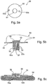
- Figs. 5a - 5c illustrate a probe, generally designated 50, of similar construction as shown in Figs. 4a - 4c , also including a base 51 coated on its underside with an adhesive layer 54, a pressure applicator 52 in the form of a column 55 of an elastomeric or spongy material covered at its upper face by a rigid cap 56, and a sensor projecting from the lower face of the elastomeric column 55 for contact with the subject's skin at the measurement site.
- the sensor is an optical sensor, including an optical transmitter 53a and an optical receiver 53b for optically sensing changes in the pulsatile arterial blood volume at the measurement site.
- Probe 50 illustrated in Figs. 5a - 5b further includes an ECG electrode 57 for sensing electrocardiograph (ECG) signals, concurrently with the measurement of changes in the pulsatile arterial blood volume by sensors 53a, 53b.
- ECG electrocardiograph
- the sensed ECG signal may also be used with the arterial blood volume measurements to detect or indicate a medical condition or physiological state of the subject, e.g., by producing a measurement of the pulse propagation velocity.
- Fig. 6 illustrates a clamping arrangement which may be used, instead of or together with the adhesive coating applied to the underside of the probe base, for clamping the probe to a restricted area of the subject's skin (e.g., the subject's wrist), which restricted area occupies a relatively small fraction of the surface perimeter of the respective body part (wrist) at the measurement site.
- a clamping arrangement which may be used, instead of or together with the adhesive coating applied to the underside of the probe base, for clamping the probe to a restricted area of the subject's skin (e.g., the subject's wrist), which restricted area occupies a relatively small fraction of the surface perimeter of the respective body part (wrist) at the measurement site.
- the probe is generally designated 60. It may be of any of the above-described constructions, with or without (preferably with) the adhesive coating (e.g., 14) on the underside of the base (e.g., 11).
- the clamp used generally designated 61 in Fig. 6 , may be, for example, a spring-loaded caliper.
- It includes one leg 62 engageable with the base of probe 60 for pressing it against the subject's skin at that location of the body part (e.g., wrist); a second leg 63 engageable with a pressure pad 64 at the opposite side of the subject's body part to apply a counter-force to the respective body part; and a third leg 64 engageable with another pressure pad 65 at a third point of contact with the body part, to thereby produce a three-point clamping arrangement on the respective body part.
- the body part e.g., wrist
- a second leg 63 engageable with a pressure pad 64 at the opposite side of the subject's body part to apply a counter-force to the respective body part
- a third leg 64 engageable with another pressure pad 65 at a third point of contact with the body part, to thereby produce a three-point clamping arrangement on the respective body part.
- the pressure applied by leg 62 against the base of the probe 60, together with the pressure generated by the pressure applicator portion of the probe (e.g., pressure applicator 12, Figs. 1a - 1c ), should preferably be above normal venous pressure, but below the diastolic arterial blood pressure, to thereby enhance the arterial pulsatile pressure measurements by the sensor (e.g. 12, Figs. 1a - 1c ) at the measurement site.
- such a clamping arrangement permits free venous drainage with respect to the measurement site (i.e., occupied by the sensor) through the tissues surrounding the measurement site, thereby preventing venous distention and blood pooling at the measurement site.
- Fig. 7 illustrates a slightly different clamping arrangement for clamping the probe, therein generally designated 30, to the body part (e.g., wrist).
- the clamping arrangement illustrated in Fig. 7 is a spring loaded bracelet, generally designated 71, encircling the respective body part (e.g., wrist).
- Bracelet 71 also includes one leg 72 for applying the appropriate pressure to the sensor 70 at one side of the body part, another leg 73 for applying a counter-pressure to a pressure pad 74 at the opposite side of the body part, and a further leg 75 for applying pressure to a further pressure pad 75 at a third point of the body part, to thereby provide a three-point mounting of the bracelet.
- the spring loaded bracelet 71 illustrated in Fig. 7 operates in the same manner as described above with respect to Fig. 6 to enhance the arterial pulsatile pressure measurements by probe 70, by unloading vascular wall tension while at the same time preventing venous distension and pooling.
- an important advantage of the novel probe constructed in accordance with the present invention is that a plurality of such probes may be used at different locations of the subject's body for measuring changes in the pulsatile arterial blood volume at each such location. Such measurements at the different measurement sites can provide further information useful for detecting and indicating various medical conditions of the subject.
- a plurality of body surface probes can be used to obtain simultaneous and comparative measurements from arterial-venous shunt rich palmar surfaces of the hand or plantar surfaces of the foot, and other parts of those limbs which have corresponding arterial-venous surfaces which are shunt poor. Such comparisons may help to accentuate the intensity of autonomic nervous system activation, since arterio-venous rich sites have greater autonomic control. Further applications of the invention utilizing two or more such probes are described below particularly with reference to Figs. 10 - 16 .
- Fig. 8 is a block diagram illustrating the main components of apparatus utilizing one, two, or more such probes.
- the apparatus includes two such probes 81, 82, which may be of any of the foregoing constructions.
- Each probe therefore, would include a base for application to the selected area of the subject's skin at the measurement site, a pressure applicator carried by the base for applying the required static pressure to the subject's skin at the measurement site, and a sensor for sensing changes in the pulsatile arterial blood volume at the measurement site, as more particularly described above. If one (or both) of the sensors included an ECG electrode (corresponding to ECG electrode 57 in Figs.
- the apparatus could be utilized not only for measuring changes in the pulsatile arterial blood volume at the respective measurement site, but also for generating ECG signals, e.g., to determine the pulse transition time and/or pulse propagation velocity. Such information would also be useful in detecting or indicating the medical condition or physiological state of the subject. As will be described, several other biopotential based or non-biopotential based signals may usefully be recorded in combination from a common probe as illustrated for the case of an ECG electrode in Figs. 5a - 5c .
- the outputs of the probes 81, 82 are applied to an amplifier and filter circuit 83, converted to digital by an A/D circuit 84, and inputted into a data processor system 85 having a CPU, storage display, etc.
- Probes 81, 82 illustrated in Fig. 8 may be wire-connected to the data processor 85 via circuits 83 and 84, or may communicate with data processor via a wireless communication link, e.g., RF, infra-red, acoustical, etc.
- a wireless communication link e.g., RF, infra-red, acoustical, etc.
- the energy supply for sensing changes in the pulsatile arterial blood volume at the respective measurement site, and for transmitting such measurements to the data processor system would be contained within the probe itself, thereby freeing the subject from attachment to the data processor.
- the latter and its supporting system may be mounted on the subject, as previously described in US Patent 6,461,305 thus providing the subject with freedom of movement.
- a sleep/wake detector such as an actigraph device can also be incorporated into a probe device or into the subject mounted processor 85 and its supporting system, as described for example in our pending published Application No. U.S. 2003/0004423 and in WO 01/64101 (Method and Apparatus for the Non-Invasive Detection of Particular Sleep-State Conditions by Monitoring the Peripheral Vascular System).
- other physiological parameters can also be sensed by the body surface probes. In principal any of the known physiological parameters which can be can be sensed from the body's surface can also be sensed, together with the arterial pulsatile volume signal.
- Examples of such parameters include: blood oxygen saturation levels sensed by the method generally known as pulse oximetry; sounds such as those related to breathing; biological potentials, such as electro-cardiography (ECG), electro-encephelography (EEG), electro-myography (EMG), electro-oculography (EOG), using at least a bipolar measurement setting; pulse transit time (PTT); local skin temperature; galvanic skin response signal (GSR); and any other known biological parameter that can be sensed from the surface of the skin.
- ECG electro-cardiography
- EEG electro-encephelography
- EMG electro-myography
- EEG electro-oculography
- PTT pulse transit time
- GSR galvanic skin response signal
- the simultaneous measurements derived from different measurement sites may provide further useful information by facilitating the measurement of bio-potentials such as ECG, EOG, EMG, EEG, etc. which require at least a single dipole for adequate measurement.
- non-biopotential signals such as skin temperature, galvanic skin response, and acoustic recordings, can further provide useful information.
- the above listed signals may be derived from the same probe device as that used for sensing changes in the pulsatile arterial blood volume at the measurement site in the manner illustrated for an ECG electrode in Figs. 5a - 5c .
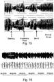
- Fig. 9 shows the acute affect of induced venous pooling and its resolution, using a previously described finger probe. More particularly, this figure shows the time-course of pulse wave amplitude in two adjacent fingers when a proximal cuff on the upper arm is alternately inflated to a pressure of 40 mmHg and then deflated back to 0 mmHg. The result of inflating the proximal cuff to 40 mmHg is to induce venous distention in the tissues distal to the cuff.
- the upper trace shows the pulse-wave amplitude recorded from the finger probe when a minimal external pressure is applied while the lower trace shows the pulse-wave amplitude recorded by the finger probe when pressure field of near diastolic pressure is applied over the entire surface of the two distal most phalanges.
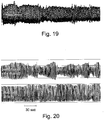
- Fig. 10 shows a similar the results of a similar experiment when the time-courses of the pulse wave amplitude sensed by a body surface probe constructed in accordance with the invention (e.g., Figs. 4a - 4c ) and mounted, respectively on the palm (lower trace) and a finger (upper trace) recorded from a finger probe in which a minimal external pressure is applied, when a proximal cuff on the upper arm is alternately inflated to a pressure of 40 mmHg and then deflated to 0 mmHg. Inflating the cuff to 40 mmHg induces venous distention in the tissues distal to the cuff.
- the upper trace is the pulse signal from a prior finger probe within minimal external counter pressure environment; and the lower trace is the pulse signal from the novel palm-mounted body surface probe within a near diastolic pressure field applied to the local measurement site only.
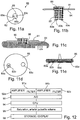
- Figs. 11a - 11e illustrate a probe, therein generally designated 80, similar to probe 50 of Figs. 5a - 5b , but particularly suitable for making pulse-oximetry measurements.
- Pulse oximetry is based on the characteristic that oxygenated hemoglobin absorbs more infrared light and allows more red light to be transmitted; while deoxygenated (or reduced) hemoglobin behaves in an opposite manner and absorbs more red light and allows more infrared light to be transmitted. At a wavelength of about 805 nm light absorption or transmission is unaffected by the level of oxygen saturation (i.e. the isobestic wavelength).
- the level of transmitted (or scattered) light can be measured using a light sensitive element.
- the wavelengths used are within the ranges of 600-750 nm (red) and 850-1000 nm (infrared). Typical values are 660 nm for red, and 920 or 940 nm for infrared, or a combination of 650nm and 805nm.
- probe 80 illustrated in Figs. 11a - 11e also includes a base 81 coated on its underside with an adhesive layer 84, a pressure applicator 82 in the form of a column 85 of an elastomeric or spongy material covered at its upper face by a rigid cap 86, and a sensor projecting from the lower face of the elastomeric column 85 for contact with the subject's skin at the measurement site.
- a pressure applicator 82 in the form of a column 85 of an elastomeric or spongy material covered at its upper face by a rigid cap 86, and a sensor projecting from the lower face of the elastomeric column 85 for contact with the subject's skin at the measurement site.
- the senor includes two transmitters 83a, 83b (e.g., LEDs) of different wavelengths, and a receiver 83c (e.g., a photo detector) spaced from the two LEDs by an opaque surface 83d to be pressed against the subject's skin.
- a receiver 83c e.g., a photo detector
- Fig. 12 is a block diagram illustrating the apparatus, generally designated 90, for utilizing the outputs of photo detector 83c for producing measurements of blood saturation level and arterial pulsatile volume.
- the photo detector 83c produces, two outputs each corresponding to the level of the light received from one of the two LEDs 83a, 83b.
- These photo detector outputs are applied as inputs 91a, 91b, to a separate amplifier/filter channel 92a, 92b for amplification and filtration, before being converted via A/D converter 93 to digital form and inputted into a CPU 94.
- CPU 94 employs the appropriate conversion equations (e.g., empirically derived) to compute the blood saturation level, arterial pulsatile volume, etc., as shown by block 94. These values are then stored and/or displayed, as shown by block 96.
- Figs. 13a and 13b illustrate a probe construction similar to that of Figs. 11a-11e , except one that it also includes a conductive element such as an ECG electrode.
- the probe then generally designated 100, also includes the two light transmitters 103a, 103b, and the receiver 103c.
- the space between the latter elements is occupied by the conductive element such as an ECG electrode 104a to enable the probe also to measure electrical potentials such as the ECG signals from the subject.
- probe 100 of Figs. 13a, 13b is otherwise the same as probe 80 of Figs. 11a-11e .
- Fig. 14 illustrates apparatus for processing the output of probe 100, which apparatus is similar to that of Fig. 12 for processing the output of probe 90, except that the apparatus of Fig. 14 also includes inputs from the two ECG electrodes 104a, 104b. Accordingly, the other elements illustrated in Fig. 14 are identified with the same reference numerals as in Fig. 12 , with the addition of the input from the ECG electrode 104a together with that from another probe being identified as inputs 91c, 91d, respectively.
- pulse oximetry is performed on the fingers, toes or ear lobes. These measurement sites are mostly composed of microcirculatory vascular beds in which there is a mixture of blood vessel types including arterial, capillary, arterio-venous and venous vessels. The admixture of arterial and venous blood at such sites is the reason why oximetry is based on the pulsatile component of the signal.
Landscapes
- Health & Medical Sciences (AREA)
- Life Sciences & Earth Sciences (AREA)
- Cardiology (AREA)
- Heart & Thoracic Surgery (AREA)
- Molecular Biology (AREA)
- Veterinary Medicine (AREA)
- Biophysics (AREA)
- Pathology (AREA)
- Engineering & Computer Science (AREA)
- Biomedical Technology (AREA)
- Vascular Medicine (AREA)
- Medical Informatics (AREA)
- Physics & Mathematics (AREA)
- Surgery (AREA)
- Animal Behavior & Ethology (AREA)
- General Health & Medical Sciences (AREA)
- Public Health (AREA)
- Physiology (AREA)
- Dentistry (AREA)
- Ophthalmology & Optometry (AREA)
- Measuring Pulse, Heart Rate, Blood Pressure Or Blood Flow (AREA)
- Measurement Of The Respiration, Hearing Ability, Form, And Blood Characteristics Of Living Organisms (AREA)
Claims (52)
- Sonde (20, 30, 40) zum Anlegen an einen ausgewählten Bereich der Haut einer Person, der ein Körperteil bedeckt, wobei der ausgewählte Bereich als Messstelle zum Messen von Änderungen des pulsierenden arteriellen Blutvolumens dort dient, umfassend:ein Unterteil (21, 31, 41) zum Anlegen auf den ausgewählten Bereich der Haut der Person an der Messstelle;einen Druckapplikator (22, 32, 42), der vom Unterteil (21, 31, 41) getragen wird, um an der Messstelle einen statischen Druck an die Haut der Person anzulegen, wenn das Unterteil daran angelegt wird;und einen Sensor (23, 33, 43), der vom Druckapplikator (22, 32, 42) getragen wird, um Änderungen des pulsierenden arteriellen Blutvolumens an der Messstelle zu erfassen, wenn das Unterteil daran angelegt ist;eine Klebeschicht (24, 34, 44), die so angeordnet ist, dass sie an einer Oberfläche des Unterteils (21, 31, 41) haftet, in dem der Druckapplikator (22, 32, 42) zentral zum ausgewählten Bereich der Haut der Person getragen wird, sodass der Druckapplikator (22, 32, 42) die Messstelle des ausgewählten Bereichs mit einem vorgegebenen statischen Druck beaufschlagt;dadurch gekennzeichnet, dass der Druckapplikator (22, 32, 42) ein elastisches Material umfasst, das konfiguriert ist, um an der Messstelle durch Anhaften der Haftschicht des Unterteils (21, 31, 41) daran einen vorgegebenen statischen Druck anzulegen, wobei ein vorgegebener statischer Druck so ausgewählt ist, dass er eine ausreichende Stärke aufweist, um die Wandspannung der Arterien an der Messstelle teilweise zu entlasten, aber die Arterien an der Messstelle nicht zu verschließen, sodass im Wesentlichen eine Venendehnung und Blutansammlung an der Messstelle verhindert wird, indem ein ausreichender äußerer Gegendruck angelegt wird, um die darunter liegenden Venen wirksam zusammenzudrücken und den lokalen venösen Blutfluss auf den arteriellen Durchsatz zu begrenzen und gleichzeitig einen freien venösen Abfluss in Bezug auf die Messstelle durch Gewebe zu ermöglichen, die die Messstelle umgeben;und dadurch, dass der Druckapplikator (22, 32, 42) konfiguriert ist, um den statischen Druck an einen relativ begrenzten Bereich der Haut der Person anzulegen, wobei dieser Bereich einen kleinen Bruchteil des Oberflächenumfangs des jeweiligen Körperteils an der Messstelle einnimmt, um dadurch einen freien Venenabfluss von der Messstelle über eine breite Region uneingeschränkter Durchgänge zu ermöglichen, die die Messstelle umgeben.
- Sonde nach Anspruch 1, wobei der Druckapplikator (22, 32, 42) an der Messstelle einen statischen Druck anlegt, der über dem lokalen Venendruck der Person und geringfügig unter dem diastolischen Blutdruck der Person liegt.
- Sonde nach Anspruch 1, wobei der Druckapplikator eine Flüssigkeitskammer umfasst, die eine elastische Wand (25) aufweist, die so aufgebaut ist, dass sie eine Flüssigkeit vollständig enthält, sodass der durch die Sonde angelegte Druck im Wesentlichen unbeeinflusst von den mechanischen Eigenschaften der darunter liegenden Gewebe ist.
- Sonde nach Anspruch 1, wobei der Druckapplikator (32) ein Gehäuse (36) mit einer Feder (35) zum Anlegen des statischen Drucks an die Messstelle umfasst.
- Sonde nach Anspruch 4, wobei die Feder (35) zum Anlegen des statischen Drucks an die Messstelle eine Schraubenfeder mit nicht komprimierter Länge ist, sodass der durch sie erzeugte wirksame Druck beim Komprimieren im Wesentlichen unbeeinflusst von relativ kleinen Schwankungen der komprimierten Länge ist, die durch die mechanischen Eigenschaften der darunter liegenden Gewebe hervorgerufen werden.
- Sonde nach Anspruch 1, wobei der Druckapplikator (42) ein elastisches Elastomermaterial (45) zum Anlegen des statischen Drucks an die Messstelle umfasst.
- Sonde nach Anspruch 6, wobei das elastische Elastomermaterial zum Anlegen des statischen Drucks an die Messstelle eine relativ große nicht komprimierte Länge aufweist, sodass der durch das Elastomermaterial erzeugte wirksame Druck im komprimierte Zustand des Elastomermaterials im Wesentlichen unbeeinflusst von relativ kleinen Schwankungen der komprimierten Länge ist, die durch die mechanischen Eigenschaften der darunterliegenden Gewebe hervorgerufen werden.
- Sonde nach Anspruch 1, wobei das Unterteil (21, 31, 41) aus einem nicht dehnbaren Material besteht und den Druckapplikator (22, 32, 42) und den Sensor (23, 33, 43) in dessen Mitte trägt.
- Sonde nach Anspruch 1, wobei das Unterteil (21, 31, 41) die Klebeschicht (24, 34, 44) auf seiner dem Druckapplikator (22, 32, 42) und dem Sensor (23, 33, 43) zugewandten Oberfläche beinhaltet, um das Unterteil an der Messstelle an der Haut der Person anzuhaften.
- Sonde nach Anspruch 1, wobei die Sonde (50) außerdem einen optischen Sensor (53a, 53b) zum Erfassen des Blutsauerstoffsättigungspegels beinhaltet.
- Sonde nach Anspruch 1, wobei die Sonde (50) außerdem eine Elektrode (57) zum Erfassen eines elektrischen Potenzials beinhaltet, beispielsweise des Elektrokardiographensignals (EKG-Signals) der Person.
- Sonde nach Anspruch 1, wobei die Sonde außerdem einen akustischen Sensor zum Erfassen eines Tonsignals der Person beinhaltet.
- Kombination einer Sonde nach Anspruch 1 mit einer Klemmvorrichtung (61) zum Anlegen einer Klemmkraft (über den Schenkel 62) an das Unterteil der Sonde (62), wenn es an die Messstelle angelegt wird, und einer Gegenkraft (über Schenkel 63) an das jeweilige Körperteil der Person an der gegenüberliegenden Seite der Messstelle.
- Vorrichtung zum Erkennen und Anzeigen eines medizinischen Zustands oder einer Änderung des physiologischen Zustands einer Person, umfassend:eine Sonde (20, 30, 40) nach Anspruch 1 zum Anlegen an eine Messstelle auf der Haut der Person und zum Erzeugen einer Ausgabe, die gemessenen Änderungen des pulsierenden arteriellen Blutvolumens daran entspricht;und ein Datenverarbeitungssystem (85) zum Verwenden der gemessenen Änderungen, um einen medizinischen Zustand oder eine Änderung des physiologischen Zustands der Person zu erkennen und anzuzeigen.
- Vorrichtung nach Anspruch 14, wobei das Datenverarbeitungssystem (85) die gemessenen Änderungen des pulsierenden Arterienvolumens verwendet, um den peripheren Arterientonus der Person anzuzeigen.
- Vorrichtung nach Anspruch 14, wobei das Datenverarbeitungssystem die gemessenen Änderungen im pulsierenden Arterienvolumen verwendet (85), um Änderungen des systemischen Blutdrucks der Person anzuzeigen.
- Vorrichtung nach Anspruch 14, wobei das Datenverarbeitungssystem (85) die gemessenen Änderungen verwendet, um die Pulsfrequenz der Person anzuzeigen.
- Vorrichtung nach Anspruch 14, wobei das Datenverarbeitungssystem (85) die gemessenen Änderungen des pulsierenden arteriellen Blutvolumens verwendet, um das Niveau des Gefäßtonus an der Messstelle anzuzeigen.
- Vorrichtung nach Anspruch 14, wobei der Sensor ein optischer Sensor (53a, 53b) ist und das Datenverarbeitungssystem (85) die gemessenen Änderungen im pulsierenden Arterienvolumen verwendet, um eine Messung des Sauerstoffsättigungsgrads des Blutes zu erzeugen.
- Vorrichtung nach Anspruch 14, wobei die Vorrichtung ferner mindestens eine weitere Sonde (80, 81) nach Anspruch 1 zum Anlegen an einer weiteren Messstelle auf der Haut der Person und zur Messung von Änderungen des pulsierenden arteriellen Blutvolumens dort umfasst; wobei das Datenverarbeitungssystem (85) die gemessenen Änderungen beider Sonden zum Erfassen und Anzeigen des medizinischen Zustands oder der Änderung des physiologischen Zustands der Person verwendet.
- Vorrichtung nach Anspruch 20, wobei die Sonden (81, 82) zum Anlegen an Messstellen konstruiert sind, bei denen die Gefäßbetten unterschiedliche Aktivitäts- oder Empfindlichkeitsniveaus des autonomen Nervensystems aufweisen.
- Vorrichtung nach Anspruch 20, wobei die Sonden (81, 82) zum Anlegen an Messstellen konstruiert sind, bei denen die Gefäßbetten dort hauptsächlich aus Leitarterien (leitenden Arterien) bzw. Mikrozirkulationsgefäßbetten bestehen.
- Vorrichtung nach Anspruch 20, wobei die Sonden (81, 82) zum Anlegen an Messstellen konstruiert sind, bei denen das pulsierende Volumen der Gefäßbetten jeweils vorwiegend durch die Aktivität des autonomen Nervensystems oder durch das Niveau des systemischen Blutdrucks beeinflusst wird.
- Vorrichtung nach Anspruch 20, wobei die Sonden (81, 82) zum Anlegen an Messstellen konstruiert sind, bei denen das pulsierende Volumen der Gefäßbetten durch die Aktivität des autonomen Nervensystems ungleichmäßig beeinflusst wird; und wobei das Datenverarbeitungssystem (85) die Ausgaben der Sonden vergleicht, um den medizinischen Zustand oder die Änderung des physiologischen Zustands der Person anzuzeigen.
- Vorrichtung nach Anspruch 20, wobei die Sonden (81, 82) zum Anlegen an zwei oder mehr Messstellen in einem bekannten Abstand voneinander konstruiert sind; und wobei das Datenverarbeitungssystem die Ausgaben der Sonden zum Anzeigen der Pulsausbreitungsgeschwindigkeit verwendet.
- Vorrichtung nach Anspruch 20, wobei mindestens eine der Sonden eine Elektrode (57) zum Erfassen des Elektrokardiographensignals (EKG-Signals) einer Person beinhaltet;
und wobei das Datenverarbeitungssystem (85) die gemessenen Änderungen des pulsierenden arteriellen Blutvolumens und des EKG-Signals verwendet, um die Pulslaufzeit und/oder die Pulsausbreitungsgeschwindigkeit zu ermitteln. - Verfahren zum Erkennen und Anzeigen einer Änderung des physiologischen Zustands einer Person, umfassend:Anlegen einer Sonde (20, 30, 40) nach Anspruch 1 an eine Messstelle auf der Haut der Person zum Messen von Änderungen des pulsierenden arteriellen Blutvolumens daran;und Verwenden der gemessenen Änderungen, um eine Änderung des physiologischen Zustands der Person zu erkennen und anzuzeigen.
- Verfahren nach Anspruch 27, wobei die Sonde (20, 30, 40) an einen relativ begrenzten Bereich der Haut der Person angelegt wird, der im Wesentlichen eine Arterie mittlerer bis großer Größe überlagert.
- Verfahren nach Anspruch 27, wobei die Sonde (20, 30, 40) an einen relativ begrenzten Bereich der Haut der Person angelegt wird, der relativ reich an arteriovenösen Anastamosengefäßen ist.
- Verfahren nach Anspruch 27, wobei die Sonde (20, 30, 40) an einen relativ begrenzten Bereich der Haut der Person angelegt wird, der relativ arm an arteriovenösen Anastamosengefäßen ist.
- Verfahren nach Anspruch 27, wobei die Sonde (20, 30, 40) an einen relativ begrenzten Bereich der Haut der Person an der Stirn der Person angelegt wird.
- Verfahren nach Anspruch 27, wobei die Sonde (20, 30, 40) an einen relativ begrenzten Bereich der Haut der Person am Unterarm der Person angelegt wird.
- Verfahren nach Anspruch 27, wobei die Sonde (20, 30, 40) an einen relativ begrenzten Bereich der Haut der Person am Handgelenk der Person angelegt wird.
- Verfahren nach Anspruch 27, wobei die Sonde an einen relativ begrenzten Bereich der Haut der Person an der Handfläche der Person oder an der Fußsohle der Person angelegt wird.
- Verfahren nach Anspruch 27, wobei der Sensor ein optischer Sensor (53a, 53b) ist und das Datenverarbeitungssystem (85) die gemessenen Änderungen des pulsierenden Arterienvolumens verwendet, um eine Messung des Sauerstoffsättigungsgrads des Blutes zu erzeugen.
- Verfahren nach Anspruch 27, wobei die Sonde (20, 30, 40) über einer oberflächlichen Arterie zur Bewertung einer endothelialen Funktion der Person angelegt wird.
- Verfahren nach Anspruch 27, wobei die Sonde (20, 30, 40) über einer Hautregion angelegt wird, die vorwiegend mikrovaskuläre Blutgefäße enthält, um eine endotheliale Funktion der Person zu bewerten.
- Verfahren nach Anspruch 27, wobei mindestens eine weitere Sonde (81, 82) an mindestens eine weitere Messstelle auf der Haut der Person angelegt wird, um das pulsierende arterielle Blutvolumen dort zu messen.
- Verfahren nach Anspruch 38, wobei die Sonden (81, 82) an Messstellen angelegt werden, bei denen die Gefäßbetten unterschiedliche Reaktivitätsgrade gegenüber autonomer Stimulation aufweisen.
- Verfahren nach Anspruch 39, wobei die Sonden (81, 82) an Messstellen angelegt werden, bei denen die Gefäßbetten davon unterschiedliche Reaktionen auf reflexauslösende Ereignisse aufweisen.
- Verfahren nach Anspruch 39, wobei mindestens eine der Sonden (81, 82) eine Elektrode (57) zum Erfassen des Elektrokardiographensignals (EKG-Signals) der Person beinhaltet, und wobei die Sonden (81, 82) in einem bekannten Abstand zueinander an Messstellen angelegt und die gemessenen Änderungen der Sonden zum Anzeigen der Pulslaufzeit und der Pulsausbreitungsgeschwindigkeit verwendet werden.
- Verfahren nach Anspruch 39, wobei eine der Sonden (81, 82) an die Körperoberfläche einer Person angelegt wird, die eine oberflächlich leitende Arterie überlagert, und eine weitere der Sonden an die Körperoberfläche einer Person angelegt wird, die über einem vorwiegend mikrozirkulatorischen Gefäßbett liegt.
- Verfahren nach Anspruch 27, wobei die Sonde über einer Hautregion angelegt wird, die vorwiegend mikrovaskuläre Blutgefäße enthält, um ein Signal für die Biofeedback-Eingabe abzuleiten.
- Verfahren nach Anspruch 27, wobei die Sonde über einer Hautregion angelegt wird, die über einer oberflächlichen Leitarterie liegt, um ein Signal für die Biofeedback-Eingabe abzuleiten.
- Verfahren nach Anspruch 27, wobei die Sonde über einer Hautregion angelegt wird, die vorwiegend mikrovaskuläre Blutgefäße enthält, um ein Signal als Reaktion auf einen physischen oder mentalen Stressfaktor abzuleiten.
- Verfahren nach Anspruch 27, wobei die Sonde über einer Hautregion angelegt wird, die über einer oberflächlich leitenden Arterie liegt, um ein Signal als Reaktion auf einen physischen oder mentalen Stressfaktor oder Stimulus abzuleiten.
- Verfahren nach Anspruch 27, wobei das Erkennen das Betrachten des zeitlichen Verlaufs eines Tonussignals einer peripheren Arterie umfasst.
- Verfahren nach Anspruch 27, wobei das Erkennen das Betrachten von Schwankungen eines Tonussignals einer peripheren Arterie umfasst.
- Verfahren nach Anspruch 39, wobei an den Messstellen eine Vielzahl verschiedener Sensoren zum Erkennen von Änderungen des pulsierenden arteriellen Blutvolumens verwendet wird.
- Verfahren nach Anspruch 39, wobei das Erkennen von Änderungen des pulsierenden arteriellen Blutvolumens an den Messstellen durchgeführt wird, um ein Signal für die Biofeedback-Eingabe abzuleiten.
- Verfahren nach Anspruch 39, wobei das Erkennen von Änderungen des pulsierenden arteriellen Blutvolumens an den Messstellen durchgeführt wird, um ein Signal als Reaktion auf einen physischen oder mentalen Stressfaktor oder Stimulus abzuleiten.
- Verfahren nach Anspruch 27, wobei der Druckapplikator (22, 32, 42) den statischen Druck an einen Bereich anlegt, der sich in einem Bereich jenseits des Bereichs des Sensors (23, 33, 43) erstreckt, um die wirksame Grenze des Druckfeldes zu erweitern, das über der Erfassungsregion liegt, um im Wesentlichen eine Venenausdehnung und Blutansammlung an der Messstelle zu verhindern und die wirksame Grenze des Druckfeldes zu erweitern, indem ein ausreichender äußerer Gegendruck angelegt wird, um die darunter liegenden Venen wirksam zu komprimieren und den lokalen venösen Blutfluss auf den arteriellen Durchsatz zu begrenzen und gleichzeitig einen freien venösen Abfluss in Bezug auf die Messstelle durch Gewebe zu ermöglichen, die die Messstelle umgeben.
Applications Claiming Priority (3)
| Application Number | Priority Date | Filing Date | Title |
|---|---|---|---|
| US39561302P | 2002-07-15 | 2002-07-15 | |
| US395613P | 2002-07-15 | ||
| PCT/IL2003/000586 WO2004006748A2 (en) | 2002-07-15 | 2003-07-15 | Body surface probe, apparatus and method for non-invasively detecting medical conditions |
Publications (3)
| Publication Number | Publication Date |
|---|---|
| EP1534115A2 EP1534115A2 (de) | 2005-06-01 |
| EP1534115A4 EP1534115A4 (de) | 2009-04-01 |
| EP1534115B1 true EP1534115B1 (de) | 2018-10-31 |
Family
ID=30115899
Family Applications (1)
| Application Number | Title | Priority Date | Filing Date |
|---|---|---|---|
| EP03764109.9A Expired - Lifetime EP1534115B1 (de) | 2002-07-15 | 2003-07-15 | Körperoberflächensonde, gerät und verfahren für den nichtinvasiven nachweis medizinischer erkrankungen |
Country Status (7)
| Country | Link |
|---|---|
| US (1) | US7621877B2 (de) |
| EP (1) | EP1534115B1 (de) |
| JP (1) | JP4395068B2 (de) |
| AU (1) | AU2003242975B2 (de) |
| CA (1) | CA2492027C (de) |
| RU (1) | RU2302196C2 (de) |
| WO (1) | WO2004006748A2 (de) |
Families Citing this family (165)
| Publication number | Priority date | Publication date | Assignee | Title |
|---|---|---|---|---|
| US6018673A (en) | 1996-10-10 | 2000-01-25 | Nellcor Puritan Bennett Incorporated | Motion compatible sensor for non-invasive optical blood analysis |
| US8932227B2 (en) | 2000-07-28 | 2015-01-13 | Lawrence A. Lynn | System and method for CO2 and oximetry integration |
| US9468378B2 (en) | 1997-01-27 | 2016-10-18 | Lawrence A. Lynn | Airway instability detection system and method |
| US9042952B2 (en) | 1997-01-27 | 2015-05-26 | Lawrence A. Lynn | System and method for automatic detection of a plurality of SPO2 time series pattern types |
| US9521971B2 (en) | 1997-07-14 | 2016-12-20 | Lawrence A. Lynn | System and method for automatic detection of a plurality of SPO2 time series pattern types |
| US20070191697A1 (en) | 2006-02-10 | 2007-08-16 | Lynn Lawrence A | System and method for SPO2 instability detection and quantification |
| US6675031B1 (en) | 1999-04-14 | 2004-01-06 | Mallinckrodt Inc. | Method and circuit for indicating quality and accuracy of physiological measurements |
| US9053222B2 (en) | 2002-05-17 | 2015-06-09 | Lawrence A. Lynn | Patient safety processor |
| US20060195041A1 (en) | 2002-05-17 | 2006-08-31 | Lynn Lawrence A | Centralized hospital monitoring system for automatically detecting upper airway instability and for preventing and aborting adverse drug reactions |
| US6754516B2 (en) * | 2001-07-19 | 2004-06-22 | Nellcor Puritan Bennett Incorporated | Nuisance alarm reductions in a physiological monitor |
| US6748254B2 (en) | 2001-10-12 | 2004-06-08 | Nellcor Puritan Bennett Incorporated | Stacked adhesive optical sensor |
| EP1565100A4 (de) | 2002-04-22 | 2008-11-19 | Marcio Marc Abreu | Vorrichtung und verfahren zur messung biologischer parameter |
| US9848815B2 (en) | 2002-04-22 | 2017-12-26 | Geelux Holdings, Ltd. | Apparatus and method for measuring biologic parameters |
| US8328420B2 (en) | 2003-04-22 | 2012-12-11 | Marcio Marc Abreu | Apparatus and method for measuring biologic parameters |
| US20080200775A1 (en) * | 2007-02-20 | 2008-08-21 | Lynn Lawrence A | Maneuver-based plethysmographic pulse variation detection system and method |
| EP1534115B1 (de) * | 2002-07-15 | 2018-10-31 | Itamar Medical Ltd | Körperoberflächensonde, gerät und verfahren für den nichtinvasiven nachweis medizinischer erkrankungen |
| US20070225614A1 (en) | 2004-05-26 | 2007-09-27 | Endothelix, Inc. | Method and apparatus for determining vascular health conditions |
| US7006856B2 (en) * | 2003-01-10 | 2006-02-28 | Nellcor Puritan Bennett Incorporated | Signal quality metrics design for qualifying data for a physiological monitor |
| US7016715B2 (en) | 2003-01-13 | 2006-03-21 | Nellcorpuritan Bennett Incorporated | Selection of preset filter parameters based on signal quality |
| US7190985B2 (en) * | 2004-02-25 | 2007-03-13 | Nellcor Puritan Bennett Inc. | Oximeter ambient light cancellation |
| US7162288B2 (en) | 2004-02-25 | 2007-01-09 | Nellcor Purtain Bennett Incorporated | Techniques for detecting heart pulses and reducing power consumption in sensors |
| US7120479B2 (en) | 2004-02-25 | 2006-10-10 | Nellcor Puritan Bennett Inc. | Switch-mode oximeter LED drive with a single inductor |
| US10227063B2 (en) | 2004-02-26 | 2019-03-12 | Geelux Holdings, Ltd. | Method and apparatus for biological evaluation |
| US8611977B2 (en) * | 2004-03-08 | 2013-12-17 | Covidien Lp | Method and apparatus for optical detection of mixed venous and arterial blood pulsation in tissue |
| US7534212B2 (en) * | 2004-03-08 | 2009-05-19 | Nellcor Puritan Bennett Llc | Pulse oximeter with alternate heart-rate determination |
| US7194293B2 (en) * | 2004-03-08 | 2007-03-20 | Nellcor Puritan Bennett Incorporated | Selection of ensemble averaging weights for a pulse oximeter based on signal quality metrics |
| US8177702B2 (en) * | 2004-04-15 | 2012-05-15 | Neuronetics, Inc. | Method and apparatus for determining the proximity of a TMS coil to a subject's head |
| US7392075B2 (en) | 2005-03-03 | 2008-06-24 | Nellcor Puritan Bennett Incorporated | Method for enhancing pulse oximetry calculations in the presence of correlated artifacts |
| DE102005031116B4 (de) * | 2005-07-04 | 2012-04-12 | Siemens Ag | Stoßwellensystem |
| US7657294B2 (en) | 2005-08-08 | 2010-02-02 | Nellcor Puritan Bennett Llc | Compliant diaphragm medical sensor and technique for using the same |
| US7590439B2 (en) | 2005-08-08 | 2009-09-15 | Nellcor Puritan Bennett Llc | Bi-stable medical sensor and technique for using the same |
| US7869850B2 (en) | 2005-09-29 | 2011-01-11 | Nellcor Puritan Bennett Llc | Medical sensor for reducing motion artifacts and technique for using the same |
| US7725147B2 (en) * | 2005-09-29 | 2010-05-25 | Nellcor Puritan Bennett Llc | System and method for removing artifacts from waveforms |
| US7725146B2 (en) | 2005-09-29 | 2010-05-25 | Nellcor Puritan Bennett Llc | System and method for pre-processing waveforms |
| US7904130B2 (en) | 2005-09-29 | 2011-03-08 | Nellcor Puritan Bennett Llc | Medical sensor and technique for using the same |
| US20070106126A1 (en) | 2005-09-30 | 2007-05-10 | Mannheimer Paul D | Patient monitoring alarm escalation system and method |
| US7486979B2 (en) | 2005-09-30 | 2009-02-03 | Nellcor Puritan Bennett Llc | Optically aligned pulse oximetry sensor and technique for using the same |
| US7483731B2 (en) | 2005-09-30 | 2009-01-27 | Nellcor Puritan Bennett Llc | Medical sensor and technique for using the same |
| US7555327B2 (en) | 2005-09-30 | 2009-06-30 | Nellcor Puritan Bennett Llc | Folding medical sensor and technique for using the same |
| US7881762B2 (en) | 2005-09-30 | 2011-02-01 | Nellcor Puritan Bennett Llc | Clip-style medical sensor and technique for using the same |
| DK1951110T3 (da) | 2005-10-24 | 2013-01-21 | Marcio Marc Aurelio Martins Abreu | Apparatur til måling af biologiske parametre |
| US7668579B2 (en) | 2006-02-10 | 2010-02-23 | Lynn Lawrence A | System and method for the detection of physiologic response to stimulation |
| RU2309668C1 (ru) | 2006-02-20 | 2007-11-10 | Александр Сергеевич Парфенов | Способ неинвазивного определения функции эндотелия и устройство для его осуществления |
| US20070208259A1 (en) * | 2006-03-06 | 2007-09-06 | Mannheimer Paul D | Patient monitoring alarm escalation system and method |
| US8702606B2 (en) * | 2006-03-21 | 2014-04-22 | Covidien Lp | Patient monitoring help video system and method |
| US7522948B2 (en) | 2006-05-02 | 2009-04-21 | Nellcor Puritan Bennett Llc | Medical sensor and technique for using the same |
| US7477924B2 (en) | 2006-05-02 | 2009-01-13 | Nellcor Puritan Bennett Llc | Medical sensor and technique for using the same |
| US8073518B2 (en) | 2006-05-02 | 2011-12-06 | Nellcor Puritan Bennett Llc | Clip-style medical sensor and technique for using the same |
| US8380271B2 (en) | 2006-06-15 | 2013-02-19 | Covidien Lp | System and method for generating customizable audible beep tones and alarms |
| US8145288B2 (en) | 2006-08-22 | 2012-03-27 | Nellcor Puritan Bennett Llc | Medical sensor for reducing signal artifacts and technique for using the same |
| US8219170B2 (en) | 2006-09-20 | 2012-07-10 | Nellcor Puritan Bennett Llc | System and method for practicing spectrophotometry using light emitting nanostructure devices |
| US8175671B2 (en) | 2006-09-22 | 2012-05-08 | Nellcor Puritan Bennett Llc | Medical sensor for reducing signal artifacts and technique for using the same |
| US8190225B2 (en) | 2006-09-22 | 2012-05-29 | Nellcor Puritan Bennett Llc | Medical sensor for reducing signal artifacts and technique for using the same |
| US8396527B2 (en) * | 2006-09-22 | 2013-03-12 | Covidien Lp | Medical sensor for reducing signal artifacts and technique for using the same |
| US7574245B2 (en) | 2006-09-27 | 2009-08-11 | Nellcor Puritan Bennett Llc | Flexible medical sensor enclosure |
| US8175667B2 (en) | 2006-09-29 | 2012-05-08 | Nellcor Puritan Bennett Llc | Symmetric LED array for pulse oximetry |
| US7684842B2 (en) | 2006-09-29 | 2010-03-23 | Nellcor Puritan Bennett Llc | System and method for preventing sensor misuse |
| US8728059B2 (en) * | 2006-09-29 | 2014-05-20 | Covidien Lp | System and method for assuring validity of monitoring parameter in combination with a therapeutic device |
| US8068890B2 (en) * | 2006-09-29 | 2011-11-29 | Nellcor Puritan Bennett Llc | Pulse oximetry sensor switchover |
| US8068891B2 (en) | 2006-09-29 | 2011-11-29 | Nellcor Puritan Bennett Llc | Symmetric LED array for pulse oximetry |
| US20080154112A1 (en) * | 2006-10-23 | 2008-06-26 | Brian Murphy | Hair-grasping EEG electrode, applicator, and method for application |
| US20080200819A1 (en) * | 2007-02-20 | 2008-08-21 | Lynn Lawrence A | Orthostasis detection system and method |
| US8265724B2 (en) | 2007-03-09 | 2012-09-11 | Nellcor Puritan Bennett Llc | Cancellation of light shunting |
| US8280469B2 (en) | 2007-03-09 | 2012-10-02 | Nellcor Puritan Bennett Llc | Method for detection of aberrant tissue spectra |
| US20080262347A1 (en) * | 2007-04-20 | 2008-10-23 | Geoffrey Batchelder | Method and apparatus for monitoring integrity of an implanted device |
| JP4569615B2 (ja) * | 2007-09-25 | 2010-10-27 | ブラザー工業株式会社 | 印刷装置 |
| US8204567B2 (en) * | 2007-12-13 | 2012-06-19 | Nellcor Puritan Bennett Llc | Signal demodulation |
| EP2229103B1 (de) * | 2007-12-17 | 2014-12-03 | Koninklijke Philips N.V. | Verfahren und system zur kompensierung der dehnungsverstärkung in der elastografie |
| US20090171167A1 (en) * | 2007-12-27 | 2009-07-02 | Nellcor Puritan Bennett Llc | System And Method For Monitor Alarm Management |
| US8092993B2 (en) | 2007-12-31 | 2012-01-10 | Nellcor Puritan Bennett Llc | Hydrogel thin film for use as a biosensor |
| US20090171173A1 (en) * | 2007-12-31 | 2009-07-02 | Nellcor Puritan Bennett Llc | System and method for reducing motion artifacts in a sensor |
| US20090171226A1 (en) * | 2007-12-31 | 2009-07-02 | Nellcor Puritan Bennett Llc | System and method for evaluating variation in the timing of physiological events |
| US20090171174A1 (en) * | 2007-12-31 | 2009-07-02 | Nellcor Puritan Bennett Llc | System and method for maintaining battery life |
| US8834382B2 (en) | 2008-01-23 | 2014-09-16 | Cardiac Profiles, Inc. | Method for determining a cardiac function |
| JP5045476B2 (ja) * | 2008-02-08 | 2012-10-10 | オムロンヘルスケア株式会社 | 血圧情報測定装置用検出ユニットおよび血圧情報測定装置 |
| US8275553B2 (en) | 2008-02-19 | 2012-09-25 | Nellcor Puritan Bennett Llc | System and method for evaluating physiological parameter data |
| US8750953B2 (en) | 2008-02-19 | 2014-06-10 | Covidien Lp | Methods and systems for alerting practitioners to physiological conditions |
| US20090247851A1 (en) * | 2008-03-26 | 2009-10-01 | Nellcor Puritan Bennett Llc | Graphical User Interface For Monitor Alarm Management |
| US8140272B2 (en) * | 2008-03-27 | 2012-03-20 | Nellcor Puritan Bennett Llc | System and method for unmixing spectroscopic observations with nonnegative matrix factorization |
| US20090247850A1 (en) * | 2008-03-28 | 2009-10-01 | Nellcor Puritan Bennett Llc | Manually Powered Oximeter |
| US8437822B2 (en) | 2008-03-28 | 2013-05-07 | Covidien Lp | System and method for estimating blood analyte concentration |
| US8292809B2 (en) | 2008-03-31 | 2012-10-23 | Nellcor Puritan Bennett Llc | Detecting chemical components from spectroscopic observations |
| US8364224B2 (en) * | 2008-03-31 | 2013-01-29 | Covidien Lp | System and method for facilitating sensor and monitor communication |
| US8112375B2 (en) | 2008-03-31 | 2012-02-07 | Nellcor Puritan Bennett Llc | Wavelength selection and outlier detection in reduced rank linear models |
| CA2722773C (en) | 2008-05-07 | 2015-07-21 | Lawrence A. Lynn | Medical failure pattern search engine |
| RU2508044C2 (ru) * | 2008-05-29 | 2014-02-27 | Итамар Медикал Лтд. | Способ и устройство обследования пациентов для выявления определенного физиологического состояния |
| US9895068B2 (en) * | 2008-06-30 | 2018-02-20 | Covidien Lp | Pulse oximeter with wait-time indication |
| USD626561S1 (en) | 2008-06-30 | 2010-11-02 | Nellcor Puritan Bennett Llc | Circular satseconds indicator and triangular saturation pattern detection indicator for a patient monitor display panel |
| USD626562S1 (en) | 2008-06-30 | 2010-11-02 | Nellcor Puritan Bennett Llc | Triangular saturation pattern detection indicator for a patient monitor display panel |
| US20090327515A1 (en) * | 2008-06-30 | 2009-12-31 | Thomas Price | Medical Monitor With Network Connectivity |
| WO2010004365A1 (en) | 2008-07-10 | 2010-01-14 | Ecole Polytechnique Federale De Lausanne (Epfl) | Functional optical coherent imaging |
| US8364220B2 (en) | 2008-09-25 | 2013-01-29 | Covidien Lp | Medical sensor and technique for using the same |
| US8417309B2 (en) | 2008-09-30 | 2013-04-09 | Covidien Lp | Medical sensor |
| US8386000B2 (en) * | 2008-09-30 | 2013-02-26 | Covidien Lp | System and method for photon density wave pulse oximetry and pulse hemometry |
| US8968193B2 (en) * | 2008-09-30 | 2015-03-03 | Covidien Lp | System and method for enabling a research mode on physiological monitors |
| US8433382B2 (en) * | 2008-09-30 | 2013-04-30 | Covidien Lp | Transmission mode photon density wave system and method |
| WO2010051487A2 (en) * | 2008-10-31 | 2010-05-06 | Nellcor Puritan Bennett Llc | System and method for facilitating observation of monitored physiologic data |
| EP2348959B1 (de) | 2008-10-31 | 2018-09-19 | Covidien LP | System zur einfacheren beobachtung von physiologischen messergebnissen |
| US8425424B2 (en) * | 2008-11-19 | 2013-04-23 | Inightee Ltd. | Closed-loop clot lysis |
| US20090171172A1 (en) * | 2008-12-19 | 2009-07-02 | Nellcor Puritan Bennett Llc | Method and system for pulse gating |
| US20100240972A1 (en) * | 2009-03-20 | 2010-09-23 | Nellcor Puritan Bennett Llc | Slider Spot Check Pulse Oximeter |
| US8221319B2 (en) | 2009-03-25 | 2012-07-17 | Nellcor Puritan Bennett Llc | Medical device for assessing intravascular blood volume and technique for using the same |
| US8057400B2 (en) | 2009-05-12 | 2011-11-15 | Angiologix, Inc. | System and method of measuring changes in arterial volume of a limb segment |
| US8509869B2 (en) | 2009-05-15 | 2013-08-13 | Covidien Lp | Method and apparatus for detecting and analyzing variations in a physiologic parameter |
| US8494786B2 (en) | 2009-07-30 | 2013-07-23 | Covidien Lp | Exponential sampling of red and infrared signals |
| US20110029865A1 (en) * | 2009-07-31 | 2011-02-03 | Nellcor Puritan Bennett Llc | Control Interface For A Medical Monitor |
| US8494606B2 (en) * | 2009-08-19 | 2013-07-23 | Covidien Lp | Photoplethysmography with controlled application of sensor pressure |
| US8494604B2 (en) * | 2009-09-21 | 2013-07-23 | Covidien Lp | Wavelength-division multiplexing in a multi-wavelength photon density wave system |
| US8704666B2 (en) * | 2009-09-21 | 2014-04-22 | Covidien Lp | Medical device interface customization systems and methods |
| US8788001B2 (en) * | 2009-09-21 | 2014-07-22 | Covidien Lp | Time-division multiplexing in a multi-wavelength photon density wave system |
| US8571621B2 (en) * | 2009-09-24 | 2013-10-29 | Covidien Lp | Minimax filtering for pulse oximetry |
| US8798704B2 (en) * | 2009-09-24 | 2014-08-05 | Covidien Lp | Photoacoustic spectroscopy method and system to discern sepsis from shock |
| US8923945B2 (en) | 2009-09-24 | 2014-12-30 | Covidien Lp | Determination of a physiological parameter |
| US8855749B2 (en) | 2009-09-24 | 2014-10-07 | Covidien Lp | Determination of a physiological parameter |
| US9554739B2 (en) | 2009-09-29 | 2017-01-31 | Covidien Lp | Smart cable for coupling a medical sensor to an electronic patient monitor |
| US8376955B2 (en) * | 2009-09-29 | 2013-02-19 | Covidien Lp | Spectroscopic method and system for assessing tissue temperature |
| US8515511B2 (en) | 2009-09-29 | 2013-08-20 | Covidien Lp | Sensor with an optical coupling material to improve plethysmographic measurements and method of using the same |
| US8401608B2 (en) | 2009-09-30 | 2013-03-19 | Covidien Lp | Method of analyzing photon density waves in a medical monitor |
| US8565847B2 (en) * | 2009-09-30 | 2013-10-22 | Covidien Lp | Evaluation board for a medical monitoring module system and method |
| US20110074342A1 (en) * | 2009-09-30 | 2011-03-31 | Nellcor Puritan Bennett Llc | Wireless electricity for electronic devices |
| US20110078596A1 (en) * | 2009-09-30 | 2011-03-31 | Nellcor Puritan Bennett Llc | Protocol Analyzer System And Method For Medical Monitoring Module |
| US8489167B2 (en) * | 2009-09-30 | 2013-07-16 | Covidien Lp | Evaluation kit for medical monitoring module system and method |
| US20110077470A1 (en) * | 2009-09-30 | 2011-03-31 | Nellcor Puritan Bennett Llc | Patient Monitor Symmetry Control |
| WO2011084800A2 (en) * | 2009-12-21 | 2011-07-14 | Carrier Corporation | Sensor mount for a mobile refrigeration system |
| US8391943B2 (en) | 2010-03-31 | 2013-03-05 | Covidien Lp | Multi-wavelength photon density wave system using an optical switch |
| US8498683B2 (en) | 2010-04-30 | 2013-07-30 | Covidien LLP | Method for respiration rate and blood pressure alarm management |
| US9380982B2 (en) | 2010-07-28 | 2016-07-05 | Covidien Lp | Adaptive alarm system and method |
| US8930145B2 (en) | 2010-07-28 | 2015-01-06 | Covidien Lp | Light focusing continuous wave photoacoustic spectroscopy and its applications to patient monitoring |
| US8610769B2 (en) | 2011-02-28 | 2013-12-17 | Covidien Lp | Medical monitor data collection system and method |
| US8577440B2 (en) | 2011-03-29 | 2013-11-05 | Covidien Lp | Method and system for positioning a sensor |
| EP2524647A1 (de) | 2011-05-18 | 2012-11-21 | Alain Gilles Muzet | System und Verfahren zur Bestimmung der Schlafstufen eines Menschen |
| GB201111138D0 (en) | 2011-06-30 | 2011-08-17 | Leman Micro Devices Uk Ltd | Personal health data collection |
| US9131900B2 (en) | 2011-07-11 | 2015-09-15 | Covidien Lp | Force regulating device applicators |
| US9220436B2 (en) | 2011-09-26 | 2015-12-29 | Covidien Lp | Technique for remanufacturing a BIS sensor |
| US10561359B2 (en) | 2011-12-02 | 2020-02-18 | Neodyne Biosciences, Inc. | Elastic devices, methods, systems and kits for selecting skin treatment devices |
| US9827447B1 (en) * | 2011-12-02 | 2017-11-28 | Neodyne Biosciences, Inc. | Devices, methods, systems and kits for selecting skin treatment devices |
| US10213350B2 (en) | 2012-02-08 | 2019-02-26 | Neodyne Biosciences, Inc. | Radially tensioned wound or skin treatment devices and methods |
| US9833146B2 (en) | 2012-04-17 | 2017-12-05 | Covidien Lp | Surgical system and method of use of the same |
| WO2013160861A1 (en) | 2012-04-27 | 2013-10-31 | Aïmago S.A. | Optical coherent imaging medical device |
| AT512304B1 (de) * | 2012-05-31 | 2013-07-15 | Cnsystems Medizintechnik Ag | Verfahren und Vorrichtung zur kontinuierlichen, nicht-invasiven Bestimmung des Blutdruckes |
| US9259343B2 (en) | 2012-07-06 | 2016-02-16 | Newman Technologies LLC | Device for mitigating plantar fasciitis |
| WO2014011107A1 (en) * | 2012-07-10 | 2014-01-16 | Delaval Holding Ab | Registering of physiological parameters based on image analysis of light reflection |
| US10101571B2 (en) * | 2012-07-10 | 2018-10-16 | Novadaq Technologies ULC | Perfusion assessment multi-modality optical medical device |
| EP2922468B1 (de) * | 2013-02-13 | 2016-06-08 | Leman Micro Devices SA | Nichtinvasive blutanalyse |
| US9700227B2 (en) | 2013-09-25 | 2017-07-11 | Bardy Diagnostics, Inc. | Ambulatory electrocardiography monitoring patch optimized for capturing low amplitude cardiac action potential propagation |
| US11723575B2 (en) | 2013-09-25 | 2023-08-15 | Bardy Diagnostics, Inc. | Electrocardiography patch |
| CA2980062A1 (en) | 2013-10-11 | 2015-04-16 | Marcio Marc Abreu | Method and apparatus for biological evaluation |
| AU2014360173B2 (en) | 2013-12-05 | 2019-05-02 | Veriskin, Inc. | Skin perfusion monitoring device |
| JP2017505657A (ja) | 2014-01-10 | 2017-02-23 | マーシオ マーク アブリュー | Abreu脳トンネルでモニタして治療を提供するデバイス |
| CN106102566A (zh) | 2014-01-10 | 2016-11-09 | 马尔西奥·马克·阿布雷乌 | 用于测量abreu脑热通道的红外输出的装置 |
| AU2015209304A1 (en) | 2014-01-22 | 2016-07-21 | Marcio Marc Abreu | Devices configured to provide treatment at an Abreu brain thermal tunnel |
| US10610113B2 (en) | 2014-03-31 | 2020-04-07 | The Regents Of The University Of Michigan | Miniature piezoelectric cardiovascular monitoring system |
| EP3267877A1 (de) | 2015-03-10 | 2018-01-17 | Marcio Marc Abreu | Vorrichtungen, einrichtungen, systeme und verfahren zur messung der temperatur eines abtt-terminus |
| CN107735015B (zh) | 2015-05-07 | 2021-09-10 | 史赛克欧洲运营有限公司 | 使用彩色图像传感器的用于组织的激光散斑成像的方法和系统 |
| CN115517627A (zh) | 2016-06-08 | 2022-12-27 | 伊塔玛医疗有限公司 | 生理和病理生理睡眠条件的非侵入性检测系统 |
| WO2018030769A1 (ko) | 2016-08-08 | 2018-02-15 | 웰빙소프트 주식회사 | 복수의 생체정보를 측정하는 휴대용 복합 센서 장치 및 측정 방법 |
| RU2638712C1 (ru) * | 2016-11-07 | 2017-12-15 | Федеральное государственное бюджетное учреждение науки Институт радиотехники и электроники им. В.А. Котельникова Российской академии наук | Пневматический сенсор для непрерывного неинвазивного измерения артериального давления |
| EP3530179A1 (de) * | 2018-02-27 | 2019-08-28 | Koninklijke Philips N.V. | Erhalt von bildern zur verwendung bei der bestimmung einer oder mehrerer eigenschaften der haut einer person |
| US20190274557A1 (en) * | 2018-03-08 | 2019-09-12 | Zhongshan Anbo Health Technology Co., Ltd. | Blood Pressure Detection Device |
| WO2020123715A1 (en) * | 2018-12-11 | 2020-06-18 | Vine Medical LLC | Validating continual probe contact with tissue during bioelectric testing |
| US10914617B1 (en) * | 2019-07-29 | 2021-02-09 | Terumo Cardiovascular Systems Corporation | Flexible sensor mount for hard shell blood reservoir |
| JP7470960B2 (ja) * | 2019-11-25 | 2024-04-19 | 株式会社oneA | 生体情報測定装置 |
| EP4578382A3 (de) | 2020-06-26 | 2025-10-08 | Ectosense NV | Vorrichtung und verfahren zur kompensation der beurteilung des peripheren arteriellen tonus |
| US12394521B2 (en) | 2020-11-11 | 2025-08-19 | Itamar Medical Ltd. | Sleep apnea test device |
| KR102782322B1 (ko) * | 2022-04-15 | 2025-03-18 | 서울대학교병원 | 청각 측면을 포함하는 의료 정보를 획득하는 스마트 단말기 |
Citations (3)
| Publication number | Priority date | Publication date | Assignee | Title |
|---|---|---|---|---|
| JPS5459786U (de) * | 1977-10-04 | 1979-04-25 | ||
| US4915116A (en) * | 1988-07-06 | 1990-04-10 | Misawa Homes Institute Of Research & Development | Fingertip pulse wave sensor |
| US5195522A (en) * | 1990-11-30 | 1993-03-23 | Ivac Corporation | Tonometry sensor calibration apparatus |
Family Cites Families (27)
| Publication number | Priority date | Publication date | Assignee | Title |
|---|---|---|---|---|
| US3412729A (en) * | 1965-08-30 | 1968-11-26 | Nasa Usa | Method and apparatus for continuously monitoring blood oxygenation, blood pressure, pulse rate and the pressure pulse curve utilizing an ear oximeter as transducer |
| US4164937A (en) * | 1976-12-02 | 1979-08-21 | Spencer William E | Equipment for detecting, monitoring, measuring, displaying and recording pulse and heartbeat |
| JPS62292137A (ja) * | 1986-06-11 | 1987-12-18 | 株式会社 シグナル テクノロジ− | 血圧測定器 |
| US4807638A (en) * | 1987-10-21 | 1989-02-28 | Bomed Medical Manufacturing, Ltd. | Noninvasive continuous mean arterial blood prssure monitor |
| JPH01117305U (de) * | 1988-01-29 | 1989-08-08 | ||
| JPH0367605U (de) * | 1989-11-01 | 1991-07-02 | ||
| JP2524278Y2 (ja) * | 1990-09-10 | 1997-01-29 | コーリン電子株式会社 | 脈波検出装置 |
| US5230342A (en) * | 1991-08-30 | 1993-07-27 | Baxter International Inc. | Blood pressure monitoring technique which utilizes a patient's supraorbital artery |
| US5368039A (en) * | 1993-07-26 | 1994-11-29 | Moses; John A. | Method and apparatus for determining blood pressure |
| US5640964A (en) * | 1995-02-16 | 1997-06-24 | Medwave, Inc. | Wrist mounted blood pressure sensor |
| US5743856A (en) * | 1995-11-06 | 1998-04-28 | Colin Corporation | Apparatus for measuring pulse-wave propagation velocity |
| IL120881A (en) * | 1996-07-30 | 2002-09-12 | It M R Medic L Cm 1997 Ltd | Method and device for continuous and non-invasive monitoring of peripheral arterial tone |
| IL124787A0 (en) | 1998-06-07 | 1999-01-26 | Itamar Medical C M 1997 Ltd | Pressure applicator devices particularly useful for non-invasive detection of medical conditions |
| US6132382A (en) * | 1998-10-16 | 2000-10-17 | Medwave, Inc. | Non-invasive blood pressure sensor with motion artifact reduction |
| WO2000062666A1 (en) * | 1999-04-21 | 2000-10-26 | Jie Kan | A noninvasive blood pressure measuring method and apparatus |
| US6332869B1 (en) * | 1999-05-07 | 2001-12-25 | Colin Corporation | Superior-and-inferior-limb blood-pressure index measuring apparatus |
| IL130939A (en) | 1999-07-14 | 2005-11-20 | Itamar Medical Ltd | Probe devices particularly useful for non-invasivedetection of medical conditions |
| CA2376011C (en) * | 1999-07-21 | 2010-01-19 | Daniel David | Physiological measuring system comprising a garment in the form of a sleeve or glove and sensing apparatus incorporated in the garment |
| US6162181A (en) * | 1999-08-16 | 2000-12-19 | Hynson; James M. | Blood pressure measurement from the hand |
| JP3495299B2 (ja) * | 1999-12-08 | 2004-02-09 | 日本コーリン株式会社 | 脈波伝播速度情報測定装置および動脈分岐部検出装置 |
| US7806831B2 (en) | 2000-03-02 | 2010-10-05 | Itamar Medical Ltd. | Method and apparatus for the non-invasive detection of particular sleep-state conditions by monitoring the peripheral vascular system |
| EP1259157B1 (de) * | 2000-03-02 | 2008-06-11 | Itamar Medical Ltd | Verfahren und vorrichtung zur nicht-invasiven bestimmung von schlafzuständen mittels überwachung des peripheren vaskularsystems |
| US6819950B2 (en) * | 2000-10-06 | 2004-11-16 | Alexander K. Mills | Method for noninvasive continuous determination of physiologic characteristics |
| IL154833A0 (en) * | 2000-10-23 | 2003-10-31 | Itamar Medical Ltd | Method and apparatus for non-invasively evaluating endothelial activity in a patient |
| US6749567B2 (en) * | 2001-05-09 | 2004-06-15 | Hemonix, Inc. | Noninvasive method of measuring physiologic parameters |
| EP1534115B1 (de) * | 2002-07-15 | 2018-10-31 | Itamar Medical Ltd | Körperoberflächensonde, gerät und verfahren für den nichtinvasiven nachweis medizinischer erkrankungen |
| RU2267989C1 (ru) * | 2004-06-11 | 2006-01-20 | Михаил Владимирович Юхно | Оптический индикатор для пластической хирургии и способ его изготовления |
-
2003
- 2003-07-15 EP EP03764109.9A patent/EP1534115B1/de not_active Expired - Lifetime
- 2003-07-15 JP JP2004521067A patent/JP4395068B2/ja not_active Expired - Lifetime
- 2003-07-15 WO PCT/IL2003/000586 patent/WO2004006748A2/en not_active Ceased
- 2003-07-15 US US10/520,273 patent/US7621877B2/en not_active Expired - Lifetime
- 2003-07-15 RU RU2005103835/14A patent/RU2302196C2/ru active
- 2003-07-15 AU AU2003242975A patent/AU2003242975B2/en not_active Ceased
- 2003-07-15 CA CA2492027A patent/CA2492027C/en not_active Expired - Lifetime
Patent Citations (3)
| Publication number | Priority date | Publication date | Assignee | Title |
|---|---|---|---|---|
| JPS5459786U (de) * | 1977-10-04 | 1979-04-25 | ||
| US4915116A (en) * | 1988-07-06 | 1990-04-10 | Misawa Homes Institute Of Research & Development | Fingertip pulse wave sensor |
| US5195522A (en) * | 1990-11-30 | 1993-03-23 | Ivac Corporation | Tonometry sensor calibration apparatus |
Also Published As
| Publication number | Publication date |
|---|---|
| WO2004006748A2 (en) | 2004-01-22 |
| JP4395068B2 (ja) | 2010-01-06 |
| WO2004006748A3 (en) | 2005-04-07 |
| CA2492027A1 (en) | 2004-01-22 |
| AU2003242975B2 (en) | 2008-04-17 |
| RU2005103835A (ru) | 2005-08-10 |
| EP1534115A2 (de) | 2005-06-01 |
| CA2492027C (en) | 2012-10-02 |
| JP2006512107A (ja) | 2006-04-13 |
| US20060064024A1 (en) | 2006-03-23 |
| RU2302196C2 (ru) | 2007-07-10 |
| EP1534115A4 (de) | 2009-04-01 |
| AU2003242975A1 (en) | 2004-02-02 |
| US7621877B2 (en) | 2009-11-24 |
Similar Documents
| Publication | Publication Date | Title |
|---|---|---|
| EP1534115B1 (de) | Körperoberflächensonde, gerät und verfahren für den nichtinvasiven nachweis medizinischer erkrankungen | |
| US9380951B2 (en) | Non-invasively monitoring blood parameters | |
| US20070167844A1 (en) | Apparatus and method for blood pressure measurement by touch | |
| GB2180944A (en) | Continuous cutaneous blood pressure measurement | |
| JP7235120B2 (ja) | 血圧計 | |
| JP2012508631A (ja) | 被検者の循環系評価 | |
| US12419528B2 (en) | Photoplethysmography-based blood pressure monitoring device | |
| EP2112902B1 (de) | Pad zur messung des systolischen blutdrucks im fussgelenk mittels ppg | |
| Liu et al. | Blood pressure monitoring techniques in the natural state of multi-scenes: A review | |
| US20070197887A1 (en) | Noninvasive vital signs sensor | |
| US20240065563A1 (en) | Blood pressure measurements using cyclic pressure on a wearable device ppg sensor | |
| KR20200129811A (ko) | 혈압 측정 시스템 및 이를 이용한 혈압 측정 방법 | |
| Wang et al. | Development of an arterial applanation tonometer for detecting arterial blood pressure and volume | |
| Meyer-Sabellek et al. | Blood pressure measurements: new techniques in automatic and in 24-hour indirect monitoring | |
| El-Khoury et al. | Portable spo2 monitor: A fast response approach | |
| Schnall et al. | A rapid noninvasive blood pressure measurement method for discrete value and full waveform determination | |
| US12268481B2 (en) | Photoplethysmography-based blood pressure monitoring device | |
| JP2681151B2 (ja) | 血圧計プローブ及び血圧測定装置 | |
| Huotari et al. | Arterial pulse wave analysis based on PPG and EMFi measurements | |
| JPH05503856A (ja) | 強化された動脈酸素飽和決定方法および動脈血圧監視方法 | |
| US20220369936A1 (en) | Blood pressure measuring device and method | |
| Wan Zaki | Monitoring the pulse arrival time using optical fibre sensors | |
| KR20260008106A (ko) | 광혈류측정법 기반 혈압 모니터링 디바이스 | |
| Mirsky et al. | Blood pressure and pulse oximetry | |
| Chellathurai | Development of a new device to measure finger's mean arterial pressure |
Legal Events
| Date | Code | Title | Description |
|---|---|---|---|
| PUAI | Public reference made under article 153(3) epc to a published international application that has entered the european phase |
Free format text: ORIGINAL CODE: 0009012 |
|
| 17P | Request for examination filed |
Effective date: 20050117 |
|
| AK | Designated contracting states |
Kind code of ref document: A2 Designated state(s): AT BE BG CH CY CZ DE DK EE ES FI FR GB GR HU IE IT LI LU MC NL PT RO SE SI SK TR |
|
| AX | Request for extension of the european patent |
Extension state: AL LT LV MK |
|
| RIC1 | Information provided on ipc code assigned before grant |
Ipc: 7A 61B 5/02 A |
|
| DAX | Request for extension of the european patent (deleted) | ||
| A4 | Supplementary search report drawn up and despatched |
Effective date: 20090304 |
|
| 17Q | First examination report despatched |
Effective date: 20090623 |
|
| STAA | Information on the status of an ep patent application or granted ep patent |
Free format text: STATUS: EXAMINATION IS IN PROGRESS |
|
| REG | Reference to a national code |
Ref country code: DE Ref legal event code: R079 Ref document number: 60351595 Country of ref document: DE Free format text: PREVIOUS MAIN CLASS: A61B0005020000 Ipc: A61B0005021000 |
|
| RIC1 | Information provided on ipc code assigned before grant |
Ipc: A61B 5/02 19680901ALI20180629BHEP Ipc: A61B 5/00 19680901ALI20180629BHEP Ipc: A61B 5/021 19900101AFI20180629BHEP |
|
| GRAP | Despatch of communication of intention to grant a patent |
Free format text: ORIGINAL CODE: EPIDOSNIGR1 |
|
| STAA | Information on the status of an ep patent application or granted ep patent |
Free format text: STATUS: GRANT OF PATENT IS INTENDED |
|
| INTG | Intention to grant announced |
Effective date: 20180821 |
|
| GRAS | Grant fee paid |
Free format text: ORIGINAL CODE: EPIDOSNIGR3 |
|
| GRAA | (expected) grant |
Free format text: ORIGINAL CODE: 0009210 |
|
| STAA | Information on the status of an ep patent application or granted ep patent |
Free format text: STATUS: THE PATENT HAS BEEN GRANTED |
|
| AK | Designated contracting states |
Kind code of ref document: B1 Designated state(s): AT BE BG CH CY CZ DE DK EE ES FI FR GB GR HU IE IT LI LU MC NL PT RO SE SI SK TR |
|
| REG | Reference to a national code |
Ref country code: GB Ref legal event code: FG4D Ref country code: CH Ref legal event code: EP |
|
| REG | Reference to a national code |
Ref country code: AT Ref legal event code: REF Ref document number: 1058400 Country of ref document: AT Kind code of ref document: T Effective date: 20181115 |
|
| REG | Reference to a national code |
Ref country code: IE Ref legal event code: FG4D |
|
| REG | Reference to a national code |
Ref country code: DE Ref legal event code: R096 Ref document number: 60351595 Country of ref document: DE |
|
| REG | Reference to a national code |
Ref country code: SE Ref legal event code: TRGR |
|
| REG | Reference to a national code |
Ref country code: CH Ref legal event code: PK Free format text: BERICHTIGUNGEN |
|
| REG | Reference to a national code |
Ref country code: NL Ref legal event code: FP |
|
| RIC2 | Information provided on ipc code assigned after grant |
Ipc: A61B 5/021 20060101AFI20180629BHEP Ipc: A61B 5/02 20060101ALI20180629BHEP Ipc: A61B 5/00 20060101ALI20180629BHEP |
|
| REG | Reference to a national code |
Ref country code: AT Ref legal event code: MK05 Ref document number: 1058400 Country of ref document: AT Kind code of ref document: T Effective date: 20181031 |
|
| PG25 | Lapsed in a contracting state [announced via postgrant information from national office to epo] |
Ref country code: BG Free format text: LAPSE BECAUSE OF FAILURE TO SUBMIT A TRANSLATION OF THE DESCRIPTION OR TO PAY THE FEE WITHIN THE PRESCRIBED TIME-LIMIT Effective date: 20190131 Ref country code: ES Free format text: LAPSE BECAUSE OF FAILURE TO SUBMIT A TRANSLATION OF THE DESCRIPTION OR TO PAY THE FEE WITHIN THE PRESCRIBED TIME-LIMIT Effective date: 20181031 Ref country code: FI Free format text: LAPSE BECAUSE OF FAILURE TO SUBMIT A TRANSLATION OF THE DESCRIPTION OR TO PAY THE FEE WITHIN THE PRESCRIBED TIME-LIMIT Effective date: 20181031 Ref country code: AT Free format text: LAPSE BECAUSE OF FAILURE TO SUBMIT A TRANSLATION OF THE DESCRIPTION OR TO PAY THE FEE WITHIN THE PRESCRIBED TIME-LIMIT Effective date: 20181031 |
|
| PG25 | Lapsed in a contracting state [announced via postgrant information from national office to epo] |
Ref country code: GR Free format text: LAPSE BECAUSE OF FAILURE TO SUBMIT A TRANSLATION OF THE DESCRIPTION OR TO PAY THE FEE WITHIN THE PRESCRIBED TIME-LIMIT Effective date: 20190201 Ref country code: PT Free format text: LAPSE BECAUSE OF FAILURE TO SUBMIT A TRANSLATION OF THE DESCRIPTION OR TO PAY THE FEE WITHIN THE PRESCRIBED TIME-LIMIT Effective date: 20190301 |
|
| PG25 | Lapsed in a contracting state [announced via postgrant information from national office to epo] |
Ref country code: DK Free format text: LAPSE BECAUSE OF FAILURE TO SUBMIT A TRANSLATION OF THE DESCRIPTION OR TO PAY THE FEE WITHIN THE PRESCRIBED TIME-LIMIT Effective date: 20181031 Ref country code: IT Free format text: LAPSE BECAUSE OF FAILURE TO SUBMIT A TRANSLATION OF THE DESCRIPTION OR TO PAY THE FEE WITHIN THE PRESCRIBED TIME-LIMIT Effective date: 20181031 Ref country code: CZ Free format text: LAPSE BECAUSE OF FAILURE TO SUBMIT A TRANSLATION OF THE DESCRIPTION OR TO PAY THE FEE WITHIN THE PRESCRIBED TIME-LIMIT Effective date: 20181031 |
|
| REG | Reference to a national code |
Ref country code: DE Ref legal event code: R097 Ref document number: 60351595 Country of ref document: DE |
|
| PG25 | Lapsed in a contracting state [announced via postgrant information from national office to epo] |
Ref country code: SK Free format text: LAPSE BECAUSE OF FAILURE TO SUBMIT A TRANSLATION OF THE DESCRIPTION OR TO PAY THE FEE WITHIN THE PRESCRIBED TIME-LIMIT Effective date: 20181031 Ref country code: EE Free format text: LAPSE BECAUSE OF FAILURE TO SUBMIT A TRANSLATION OF THE DESCRIPTION OR TO PAY THE FEE WITHIN THE PRESCRIBED TIME-LIMIT Effective date: 20181031 Ref country code: RO Free format text: LAPSE BECAUSE OF FAILURE TO SUBMIT A TRANSLATION OF THE DESCRIPTION OR TO PAY THE FEE WITHIN THE PRESCRIBED TIME-LIMIT Effective date: 20181031 |
|
| PLBE | No opposition filed within time limit |
Free format text: ORIGINAL CODE: 0009261 |
|
| STAA | Information on the status of an ep patent application or granted ep patent |
Free format text: STATUS: NO OPPOSITION FILED WITHIN TIME LIMIT |
|
| 26N | No opposition filed |
Effective date: 20190801 |
|
| PG25 | Lapsed in a contracting state [announced via postgrant information from national office to epo] |
Ref country code: SI Free format text: LAPSE BECAUSE OF FAILURE TO SUBMIT A TRANSLATION OF THE DESCRIPTION OR TO PAY THE FEE WITHIN THE PRESCRIBED TIME-LIMIT Effective date: 20181031 |
|
| PG25 | Lapsed in a contracting state [announced via postgrant information from national office to epo] |
Ref country code: MC Free format text: LAPSE BECAUSE OF FAILURE TO SUBMIT A TRANSLATION OF THE DESCRIPTION OR TO PAY THE FEE WITHIN THE PRESCRIBED TIME-LIMIT Effective date: 20181031 |
|
| REG | Reference to a national code |
Ref country code: CH Ref legal event code: PL |
|
| PG25 | Lapsed in a contracting state [announced via postgrant information from national office to epo] |
Ref country code: TR Free format text: LAPSE BECAUSE OF FAILURE TO SUBMIT A TRANSLATION OF THE DESCRIPTION OR TO PAY THE FEE WITHIN THE PRESCRIBED TIME-LIMIT Effective date: 20181031 |
|
| REG | Reference to a national code |
Ref country code: BE Ref legal event code: MM Effective date: 20190731 |
|
| PG25 | Lapsed in a contracting state [announced via postgrant information from national office to epo] |
Ref country code: BE Free format text: LAPSE BECAUSE OF NON-PAYMENT OF DUE FEES Effective date: 20190731 Ref country code: LU Free format text: LAPSE BECAUSE OF NON-PAYMENT OF DUE FEES Effective date: 20190715 Ref country code: CH Free format text: LAPSE BECAUSE OF NON-PAYMENT OF DUE FEES Effective date: 20190731 Ref country code: LI Free format text: LAPSE BECAUSE OF NON-PAYMENT OF DUE FEES Effective date: 20190731 |
|
| PG25 | Lapsed in a contracting state [announced via postgrant information from national office to epo] |
Ref country code: IE Free format text: LAPSE BECAUSE OF NON-PAYMENT OF DUE FEES Effective date: 20190715 |
|
| PG25 | Lapsed in a contracting state [announced via postgrant information from national office to epo] |
Ref country code: CY Free format text: LAPSE BECAUSE OF FAILURE TO SUBMIT A TRANSLATION OF THE DESCRIPTION OR TO PAY THE FEE WITHIN THE PRESCRIBED TIME-LIMIT Effective date: 20181031 |
|
| PG25 | Lapsed in a contracting state [announced via postgrant information from national office to epo] |
Ref country code: HU Free format text: LAPSE BECAUSE OF FAILURE TO SUBMIT A TRANSLATION OF THE DESCRIPTION OR TO PAY THE FEE WITHIN THE PRESCRIBED TIME-LIMIT; INVALID AB INITIO Effective date: 20030715 |
|
| PGFP | Annual fee paid to national office [announced via postgrant information from national office to epo] |
Ref country code: NL Payment date: 20210721 Year of fee payment: 19 |
|
| PGFP | Annual fee paid to national office [announced via postgrant information from national office to epo] |
Ref country code: FR Payment date: 20210727 Year of fee payment: 19 |
|
| PGFP | Annual fee paid to national office [announced via postgrant information from national office to epo] |
Ref country code: GB Payment date: 20210721 Year of fee payment: 19 Ref country code: SE Payment date: 20210721 Year of fee payment: 19 Ref country code: DE Payment date: 20210721 Year of fee payment: 19 |
|
| REG | Reference to a national code |
Ref country code: DE Ref legal event code: R119 Ref document number: 60351595 Country of ref document: DE |
|
| REG | Reference to a national code |
Ref country code: SE Ref legal event code: EUG |
|
| REG | Reference to a national code |
Ref country code: NL Ref legal event code: MM Effective date: 20220801 |
|
| GBPC | Gb: european patent ceased through non-payment of renewal fee |
Effective date: 20220715 |
|
| PG25 | Lapsed in a contracting state [announced via postgrant information from national office to epo] |
Ref country code: SE Free format text: LAPSE BECAUSE OF NON-PAYMENT OF DUE FEES Effective date: 20220716 Ref country code: FR Free format text: LAPSE BECAUSE OF NON-PAYMENT OF DUE FEES Effective date: 20220731 |
|
| PG25 | Lapsed in a contracting state [announced via postgrant information from national office to epo] |
Ref country code: GB Free format text: LAPSE BECAUSE OF NON-PAYMENT OF DUE FEES Effective date: 20220715 Ref country code: DE Free format text: LAPSE BECAUSE OF NON-PAYMENT OF DUE FEES Effective date: 20230201 |
|
| PG25 | Lapsed in a contracting state [announced via postgrant information from national office to epo] |
Ref country code: NL Free format text: LAPSE BECAUSE OF NON-PAYMENT OF DUE FEES Effective date: 20220801 |