EP1534019A2 - Methode und Vorrichtung zur Kompensation der Luminanz eines Farbsignals - Google Patents
Methode und Vorrichtung zur Kompensation der Luminanz eines Farbsignals Download PDFInfo
- Publication number
- EP1534019A2 EP1534019A2 EP04255658A EP04255658A EP1534019A2 EP 1534019 A2 EP1534019 A2 EP 1534019A2 EP 04255658 A EP04255658 A EP 04255658A EP 04255658 A EP04255658 A EP 04255658A EP 1534019 A2 EP1534019 A2 EP 1534019A2
- Authority
- EP
- European Patent Office
- Prior art keywords
- luminance
- ratio
- color signal
- result
- allowable
- Prior art date
- Legal status (The legal status is an assumption and is not a legal conclusion. Google has not performed a legal analysis and makes no representation as to the accuracy of the status listed.)
- Withdrawn
Links
Images


Classifications
-
- H—ELECTRICITY
- H04—ELECTRIC COMMUNICATION TECHNIQUE
- H04N—PICTORIAL COMMUNICATION, e.g. TELEVISION
- H04N9/00—Details of colour television systems
- H04N9/64—Circuits for processing colour signals
- H04N9/646—Circuits for processing colour signals for image enhancement, e.g. vertical detail restoration, cross-colour elimination, contour correction, chrominance trapping filters
-
- G—PHYSICS
- G06—COMPUTING OR CALCULATING; COUNTING
- G06T—IMAGE DATA PROCESSING OR GENERATION, IN GENERAL
- G06T5/00—Image enhancement or restoration
- G06T5/90—Dynamic range modification of images or parts thereof
- G06T5/92—Dynamic range modification of images or parts thereof based on global image properties
-
- H—ELECTRICITY
- H04—ELECTRIC COMMUNICATION TECHNIQUE
- H04N—PICTORIAL COMMUNICATION, e.g. TELEVISION
- H04N1/00—Scanning, transmission or reproduction of documents or the like, e.g. facsimile transmission; Details thereof
- H04N1/46—Colour picture communication systems
- H04N1/56—Processing of colour picture signals
- H04N1/60—Colour correction or control
- H04N1/6027—Correction or control of colour gradation or colour contrast
-
- H—ELECTRICITY
- H04—ELECTRIC COMMUNICATION TECHNIQUE
- H04N—PICTORIAL COMMUNICATION, e.g. TELEVISION
- H04N9/00—Details of colour television systems
- H04N9/77—Circuits for processing the brightness signal and the chrominance signal relative to each other, e.g. adjusting the phase of the brightness signal relative to the colour signal, correcting differential gain or differential phase
-
- G—PHYSICS
- G06—COMPUTING OR CALCULATING; COUNTING
- G06T—IMAGE DATA PROCESSING OR GENERATION, IN GENERAL
- G06T2207/00—Indexing scheme for image analysis or image enhancement
- G06T2207/10—Image acquisition modality
- G06T2207/10024—Color image
Definitions
- the present invention relates to a multi-color image display such as a display monitor or a color television, and more particularly, to a method for compensating for the luminance of a color signal, which is performed by a multi-color image display, and an apparatus for compensating for the luminance of a color signal, which is included in the multi-color image display.
- achromatic color series In a multi-color image display which displays more primary colors than four or four primary colors, synthetic colors created by mixing more primary colors than three or three primary colors, for example, achromatic color series are high in luminance, while color signals of primary color series are relatively low in luminance comparing to the synthetic colors.
- the color signal of primary color series means each primary color or color signals near to a line or an area connecting two primary colors. Especially, in a case where the number of the primary colors is more than four or four, a difference between the luminance of a color signal of primary color series and that of a synthetic color becomes greater.
- FIG. 1 shows an example in which a color gamut of a multi-color image display representing four primary colors is illustrated on a two-dimensional plane using a red-color (R) axis and a green-color (G) axis.
- an arbitrary color signal represented by the multi-color image display has a unique coordinate within a hexahedron Org-Q3-Q1-Q4-Q5-Q6 in a color coordinate space.
- a three-color image display is a hexahedron in a three-dimensional space and a square in a two-dimensional space
- a multi-color image display is a heptahedron or a polyhedron with more faces than the heptahedron in the three-dimensional space and is a pentahedron or a polyhedron with more faces than the pentahedron in the two-dimensional space.
- color signals with low saturation are distributed in the interior of the color area Org-Q1-Q4-Q5 shown in FIG. 1 and vector lengths (or, luminance magnitude or luminance amount) of the color signals within this color area Org-Q1-Q4-Q5 have predetermined values.
- color signals with high saturation are distributed in the interiors of color areas Org-Q3-Q1 and Org-Q6-Q5, and vector lengths of the color signals within the color areas have values smaller than the predetermined values and are changed according to the saturation.
- FIG. 2 is a view in which the color gamut of the multi-color image display of FIG. 1 is illustrated on a two-dimensional plane with a saturation axis and a luminance ratio axis, wherein Q1 through Q6 correspond respectively to Q1 through Q6 shown in FIG. 1.
- a gamma function can be applied only to a luminance component Y as in a broadcast standard or can be applied to each of components of RGB.
- a RGB signal is divided into a luminance signal Y and two color difference signals (Cb and Cr) or (I and Q), a gamma function is applied to the luminance signal Y to increase the luminance, and then the result is converted to a RGB signal.
- this conventional luminance enhancing method performs color enhancing on entire color areas, a luminance difference between a color with high saturation and a color with low saturation exists.
- Still another one among the conventional luminance enhancing methods is a method using a histogram equalization disclosed in the title of "Digital Image Processing” by W.K. Pratt, published in Wiley's publishing company, in 1978, and in the title of "Digital Image Processing” by R.C. Gonzalez and R.E. Woods, published in Addition-Wesley's publishing company located in Massachusetts, in 1993.
- the above-mentioned conventional luminance enhancing methods increase the luminance and contrast throughout all ranges of pixel values in an image. As such, since the conventional luminance enhancing methods perform luminance enhancing on entire color areas, a luminance difference between a color with high saturation and a color with low saturation still exists.
- a color signal luminance compensation method comprising: obtaining an allowable luminance ratio of a color signal, obtaining a luminance enhancing ratio of the color signal using the allowable luminance ratio, and compensating for the luminance of the color signal using the luminance enhancing ratio, wherein the luminance ratio is a luminance ratio to saturation when a color signal is represented by more multiple primary colors than four, compared to a luminance ratio to saturation when the color signal is represented by three colors.
- a color signal luminance compensation apparatus comprising: an allowable luminance ratio calculator, which calculates an allowable luminance ratio of a color signal; a luminance enhancing ratio calculator, which calculates a luminance enhancing ratio of the color signal from the allowable luminance ratio; and a luminance compensator, which compensates for a luminance of the color signal using the luminance enhancing ratio; wherein the luminance ratio is a luminance ratio to saturation when the color signal is represented by more multiple primary colors than four, compared to a luminance ratio to saturation when the color signal is represented by three colors.
- the present invention provides a method for compensating for the luminance of a color signal, capable of enhancing the luminance value of an arbitrary color signal placed in a color gamut or coordinator created by multiple colors according to the saturation of the corresponding color signal, in a multi-color image display.
- the present invention also provides an apparatus for compensating for the luminance value of a color signal, capable of enhancing the luminance value of a color signal placed in a specific color area or coordinate according to the saturation of the corresponding color signal.
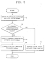
- FIG. 3 is a flowchart illustrating a method of compensating for the luminance of a color signal, according to an embodiment of the present invention, wherein the luminance compensation method consists of steps 10 through 18 which compensate for the luminance of a color signal using a luminance enhancing ratio obtained from an allowable luminance ratio of the color signal.
- the luminance ratio corresponds to a ratio between luminance according to saturation when a color signal is represented by multiple colors, and a luminance according to saturation when the color signal is represented by three colors.
- step 10 it is determined in step 12 whether the allowable luminance ratio is smaller than a predetermined value.
- the predetermined value may be a maximum luminance ratio of a color signal. That is, as seen in FIGS. 1 and 2, since a color range in which luminance is enhanced is Q1 through Q3 or Q5 through Q6, a luminance ratio at the location of Q1 or Q5 can be a predetermined value as a luminance enhancing threshold value.
- the predetermined value is a result obtained by dividing a luminance level of a corresponding pixel at a maximum value of an intensity level of the color component X by a luminance level of a corresponding pixel at a maximum value of an intensity level of RGBX. That is, the predetermined value C1 can be expressed by the following Equation 1.
- C 1 Lu minance( X - channel ) Lu min ance ( RGBX - channel )
- Luminance (X-channel) is a luminance level of a pixel represented by RGBX when an intensity level of the RGB is minimal and an intensity level of X is maximal
- Luminance (RGBX-channel) is a luminance level of a pixel represented by RGBX when the intensity level of the RGBX is maximal.
- the color signal is bypassed without any compensation in step 14.
- a luminance enhancing ratio of the color signal is obtained using the allowable luminance ratio in step 16. Also, if it is determined that the allowable luminance ratio is smaller than the predetermined value, the luminance enhancing ratio can be obtained using the predetermined value as well as the allowable luminance ratio in step 16. After step 16, in step 18, the luminance of the color signal is compensated for, using the luminance enhancing ratio.
- the color signal luminance compensation method consists of steps 10 through 18.
- the color signal luminance compensation method can consist of steps 10, 14, 16 and 18.
- step 10 a luminance enhancing ratio of the color signal is obtained in step 16.
- the luminance of the color signal is compensated for in step 18 or the color signal is bypassed in step 14 without compensation for the luminance of the color signal.
- the luminance enhancing ratio obtained in step 16 is "0"
- the luminance of the color signal is not compensated for in step 14.
- the luminance enhancing ratio obtained in step 16 is not "0"
- the luminance of the color signal is compensated for in step 18.
- step 10 shown in FIG. 3 will be described with reference to the appended drawings.
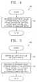
- FIG. 4 is a flowchart illustrating an embodiment 10A of step 10 of FIG. 3, according to the present invention, wherein the embodiment 10A consists of step 20 which decides an outer most value corresponding to a color signal as an allowable luminance ratio.
- an outer most value corresponding to a color signal among pre-stored outer most values capable of being represented in a multi-dimensional color space is decided as an allowable luminance ratio, in step 20.
- FIG. 5 is a flowchart illustrating another embodiment 10B of step 10 of FIG. 3, according to the present invention, wherein the embodiment 10B consists of steps 30 and 32 which decide an outer most value corresponding to a saturation value of a color signal as an allowable luminance ratio.
- a saturation value of a color signal is obtained in step 30.
- FIG. 6 is a flowchart illustrating an embodiment 30A of step 30 of FIG. 5, according to the present invention, wherein the embodiment 30A consists of steps 40 and 42 which obtain a saturation value using a maximum value and a minimum value of intensity levels of a color signal.
- X1, X2, and X3 represent intensity levels of channels of a color signal and can be negative values.
- Max(X1, X2, X3) represents a maximum value of the intensity levels X1, X2 and X3 of channels of the color signal and
- Min(X1, X2, X3) represents a minimum value of the intensity levels X1, X2 and X3 of the channels of the color signal.
- an outer most value corresponding to a saturation value among pre-stored outer most values capable of being represented in a multi-dimensional color space is decided as an allowable luminance value in step 32.
- FIG. 7 is a flowchart illustrating still another embodiment 10C of step 10 of FIG. 3, according to the present invention, wherein the embodiment 10C consists of steps 50 through 54 which obtain an allowable luminance ratio using a maximum value and a minimum value of intensity levels X1, X2 and X3 of channels of a color signal.
- a maximum value Max(X1, X2, X3) and a minimum value Min(X1, X2, X3) of the intensity levels X1, X2 and X3 of the channels of a color signal are obtained in step 50.
- the minimum value Min(X1, X2, X3) is subtracted from the Maximum value Max(X1, X2, X3).
- the maximum value is divided by the subtracted result and the divided result is decided as an allowable luminance ratio. That is, the allowable luminance ratio aBrt can be expressed by Equation 3.
- aBrt Max ( X 1 ,X 2 ,X 3) Max ( X 1, X 2, X 3)- Min ( X 1, X 2, X 3)
- step 12 If step 12 is not provided to the color signal luminance compensation method shown in FIG. 3, process proceeds to step 16 instead of step 12 after steps 20, 32 and 54 shown in FIGS. 4, 5 or 7.
- FIG. 8 is a flowchart illustrating a preferred embodiment 16A of step 16 of FIG. 3, according to the present invention, wherein the embodiment 16A consists of step 60 which selects a luminance enhancing ratio corresponding to an allowable luminance ratio.
- a luminance enhancing ratio corresponding to an allowable luminance ratio among pre-stored luminance enhancing ratios is selected and process proceeds to step 18, in step 60.
- FIG. 9 is a flowchart illustrating another preferred embodiment 16B of step 16 of FIG. 3, according to the present invention wherein the process 16B consists of step 70 which obtains a luminance enhancing ratio by subtracting the allowable luminance ratio from a predetermined value.
- step 70 the allowable luminance ratio is subtracted from the predetermined value, the subtracted result is decided as a luminance enhancing ratio and process proceeds to step 18. That is, the luminance enhancing ratio B_inc can be expressed by Equation 4.
- B_inc C2 X (C1 - aBrt)
- C2 is a first control constant and the magnitude of the luminance enhancing ratio B_inc can be changed by the first control constant.
- FIG. 10 is a flowchart illustrating still another preferred embodiment 16C of step 16 of FIG. 3, according to the present invention, wherein the embodiment 16C consists of step 80 which obtains a luminance enhancing ratio by dividing an allowable luminance ratio by a predetermined value.
- step 80 the allowable luminance ratio is divided by the predetermined value, the divided result is decided as a luminance enhancing ratio and process proceeds to step 18. That is, the luminance enhancing ratio B_inc can be expressed by Equation 5.
- B _ inc C3 ⁇ aBrt C 1
- C3 is a second control constant and the magnitude of the luminance enhancing ratio B_inc can be changed by the second control constant.
- FIG. 11 is a flowchart illustrating an embodiment 18A of step 18 of FIG. 3, according to the present invention, wherein the embodiment 18A consists of steps 90 through 96 which compensate for the luminance of a color signal using a maximum intensity level and a luminance enhancing ratio.
- step 90 an intensity level Xi of each Pi (1 ⁇ i ⁇ 3) of channels of a color signal is subtracted from a maximum intensity level of each channel Pi of the color signal.
- the result subtracted in step 90 is divided by the maximum intensity level in step 92.
- the divided result is multiplied by the luminance enhancing ratio and the intensity level Xi in step 94.
- step 94 the multiplied result is added to the intensity level Xi and the added result is decided as a luminance-compensated result Pi' of the channel Pi, in step 96. That is, the luminance-compensated result Pi' of each the channel Pi of the color signal can be expressed by Equation 6.
- Pi ' Xi ⁇ (1 + B_inc max Value - Xi max Value )
- maxValue is a maximum intensity level of each channel Pi of a color signal and corresponds to 256 if the color signal is a 8-bit signal.
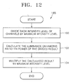
- FIG. 12 is a flowchart illustrating another embodiment 18B of step 18 of FIG. 3, according to the present invention, wherein the embodiment 18B consists of steps 100 through 104 which compensate for the luminance of a color signal using a maximum intensity level and a luminance enhancing ratio.
- an intensity level Xi of each channel Pi of a color signal is divided by a maximum intensity level maxValue of each the channel Pi of the color signal in step 100.
- the luminance enhancing ratio (B_inc)-th power of the divided result is calculated.
- the calculated result is multiplied by the maximum intensity level maxValue and the multiplied result is decided as a luminance-compensated result Pi' of the channel Pi in step 104. That is, the luminance-compensated result Pi' of each the channel Pi of the color signal can be expressed by Equation 7.
- Pi ' ( Xi max Value ) B _inc ⁇ X max Value
- FIG. 13 is a flowchart illustrating still another embodiment 18C of step 18 of FIG. 3, according to the present invention, wherein the embodiment 18C consists of steps 110 through 116 which compensate for the luminance of a color signal using a maximum intensity level and a luminance enhancing ratio.
- a maximum value Max of intensity levels X1, X2 and X3 of channels of a color signal is subtracted from a maximum intensity level maxValue of each the channel Pi of the color signal in step 110.
- the subtracted result is divided by the maximum intensity level maxValue in step 112.
- the divided result is multiplied by the luminance enhancing ratio B_inc and the maximum value Max in step 114.
- the multiplied result is added with the maximum value Max and the added result is decided as a luminance-compensated result Pi' of the channel Pi in step 116. That is, the luminance-compensated result Pi' of the color signal can be expressed by Equation 8.
- Pi ' Max ⁇ (1 + B_inc max Value - Max max Value )
- Steps 90 through 96 shown in FIG. 11 are performed on each channel Pi of a color signal
- steps 100 through 104 shown in FIG. 12 are performed on each channel Pi of the color signal
- steps 110 through 116 shown in FIG. 13 are performed on each channel Pi of the color signal.
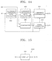
- FIG. 14 is a block diagram of a color signal luminance compensation apparatus according to an embodiment of the present invention, wherein the luminance compensation apparatus includes an allowable luminance ratio calculator 200, a luminance enhancing ratio calculator 202, a luminance compensation unit 204, a comparator 206 and a signal connector 208.
- the luminance compensation apparatus includes an allowable luminance ratio calculator 200, a luminance enhancing ratio calculator 202, a luminance compensation unit 204, a comparator 206 and a signal connector 208.
- the luminance compensation apparatus shown in FIG. 14 serves to perform the color signal luminance compensation method shown in FIG. 3.
- the allowance luminance ratio calculator 200 calculates an allowable luminance ratio of a color signal received through an input terminal IN1 and outputs the calculated allowable luminance ratio respectively to the luminance enhancing ratio calculator 202 and the comparator 206.
- the comparator 206 compares the allowable luminance ratio received from the allowable luminance ratio calculator 200 with a predetermined value received through an input terminal IN2, and outputs the compared result.
- the signal connector 208 outputs the color signal received through the input terminal IN1 to the luminance compensation unit 204 or bypasses the color signal to an external source through an output terminal OUT1, in response to the compared result from the comparator 206. If the signal connector 208 determines through the compared result received from the comparator 206 that the allowable luminance ratio exceeds a predetermined value, the signal connector 208 bypasses the color signal received through the input terminal IN1 to the output terminal OUT1 without compensating for the luminance of the color signal in order to perform step 14.
- the signal connector 208 determines through the compared result received from the comparator 206 that the allowable luminance ratio is smaller than the predetermined value, the signal connector 208 outputs the color signal received through the input terminal IN1 to the luminance compensation unit 204.
- the luminance enhancing ratio calculator 202 calculates a luminance enhancing ratio of the color signal using the allowable luminance ratio received from the allowable luminance ratio calculator 200, and outputs the calculated allowable enhancing ratio to the luminance compensator 204. At this time, the luminance enhancing ratio calculator 202 can calculates a luminance enhancing ratio using the allowable luminance ratio received from the allowable luminance ratio calculator 200 and the predetermined value received through the input terminal IN2.
- the luminance enhancing ratio calculator 202 can calculate a luminance enhancing ratio in response to the result compared by the comparator 206. For example, if it is determined through the compared result received from the comparator 206 that the allowable luminance ratio is smaller than the predetermined value, the luminance enhancing ratio calculator 202 calculates a luminance enhancing ratio of the color signal. However, if it is determined through the compared result received from the comparator 206 that the allowable luminance ratio exceeds the predetermined value, the luminance enhancing ratio calculator 202 does not calculate the luminance enhancing ratio of the color signal.
- the luminance compensator 204 compensates for the luminance of a color signal received from the signal connector 208 using the luminance enhancing ratio received from the luminance enhancing ratio calculator 202, and outputs a luminance-compensated result through an output terminal OUT2.
- the luminance-compensated result is output to a display panel (not shown) or a multi-color calculator (not shown).
- the display panel processes the luminance-compensated result so that the luminance-compensated result can be displayed.
- the multi-color calculator pre-processes the luminance-compensated result and then transfers the pre-processed result to the display panel.
- the luminance compensator 204 can perform step 14 or step 18 in response to the luminance enhancing ratio received from the luminance enhancing ratio calculator 202.
- the luminance enhancing ratio calculator 202 calculates a luminance enhancing ratio using Equation 4, if a luminance enhancing ratio received from the luminance enhancing ratio calculator 202 is "0", the luminance compensator 204 bypasses the luminance of a color signal received through the input terminal IN1 to the output terminal OUT2 without compensating for the luminance of the color signal, in step 14.
- the luminance compensator 204 compensates for the luminance of the color signal received through the input terminal IN1 and outputs the luminance-compensated result through the output terminal OUT2 in step 18.
- FIG. 15 is a block diagram of the allowable luminance ratio calculator 200 of FIG. 14, according to a preferred embodiment 200A of the present invention, wherein the allowable luminance ratio calculator 200A consists of a first lookup table (LUT) 220.
- LUT first lookup table
- the allowable luminance ratio calculator 200A of FIG. 15 serves to perform step 10A of FIG. 4. That is, to perform step 20, the first LUT 220 stores in advance, as data, outer most values capable of being represented in a multi-dimensional color space in advance, reads a corresponding outer most value in response to a color signal received through an input terminal IN3 as an address, and outputs the read value as an allowable luminance ratio through an output terminal OUT3 to the luminance enhancing ratio calculator 202 and the comparator 206. For that, a relationship between three channel intensity levels X1, X2 and X3 of a color signal received through the input terminal IN3 and an allowable luminance ratio is stored in advance in the lookup table.
- FIG. 16 is a block diagram of the allowable luminance ratio calculator 200 of FIG. 14, according to another preferred embodiment 200B of the present invention, wherein the allowable luminance ratio calculator 200B consists of a saturation calculator 230 and a second lookup table (LUT) 232.
- the allowable luminance ratio calculator 200B consists of a saturation calculator 230 and a second lookup table (LUT) 232.
- the allowable luminance ratio calculator 200B shown in FIG. 16 serves to perform step 10B of FIG. 5. That is, to perform step 30, the saturation calculator 230 calculates a saturation value of a color signal received through an input terminal IN4 and outputs the calculated saturation value to the second LUT 232. At this time, to perform step 32, the second LUT 232 stores, as data, outer most values capable of being represented in a multi-dimensional color space in advance, reads a corresponding outer most value in response to a saturation value received from the saturation calculator 230 as an address, and outputs the read value as an allowable luminance ratio through an output terminal OUT4 to the luminance enhancing ratio calculator 202 and the comparator 206.
- FIG. 17 is a block diagram of the allowable luminance ratio calculator 200 of FIG. 14, according to still another preferred embodiment 200C of the present invention, wherein the allowable luminance ratio calculator 200C consists of a minimum value extractor 250, a maximum value extractor 252, a first subtractor 254 and a first divider 256.
- the allowable luminance ratio calculator 200C shown in FIG. 17 serves to perform step 10C shown in FIG. 7. That is, the minimum value extractor 250 and the maximum value extractor 252 serve to perform step 50.
- the minimum value extractor 250 extracts a minimum value of intensity levels of channels of a color signal received through an input terminal IN5 and outputs the extracted minimum value to the first subtractor 254.
- the maximum value extractor 252 extracts a maximum value of intensity levels of channels of a color signal received through the input terminal IN5 and outputs the extracted maximum value to the first subtractor 254.
- the first subtractor 254 subtracts a minimum value received from the minimum value extractor 250 from a maximum value received from the maximum value extractor 252 and outputs the subtracted result to the first divider 256.
- the first divider 256 divides the maximum value received from the maximum value extractor 252 by the result subtracted by the first subtractor 254 and outputs the divided result as an allowable luminance ratio through the output terminal OUT5 to the luminance enhancing ratio calculator 202 and the comparator 206.
- FIG. 18 is a block diagram of the luminance enhancing ratio calculator 202 of FIG. 14, according to a preferred embodiment 202A of the present invention, wherein the luminance enhancing ratio calculator 202A consists of a third LUT 270.
- the luminance enhancing ratio calculator 202A shown in FIG. 18 serves to perform step 16A shown in FIG. 8.
- the third LUT 270 stores luminance enhancing ratios as data in advance, and reads a corresponding luminance enhancing ratio in response to an allowable luminance ratio received from the allowable luminance ratio calculator 200 through an input terminal IN6 as an address, and outputs the read ratio to the luminance compensator 204 through an output terminal OUT6.
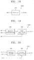
- FIG. 19 is a block diagram of the luminance enhancing ratio calculator 202 of FIG. 14, according to another preferred embodiment 202B of the present invention, wherein the luminance enhancing ratio calculator 202B consists of a second subtractor 280 and a first multiplier 282.
- the luminance enhancing ratio calculator 202B shown in FIG. 19 serves to perform step 16B shown in FIG. 9.
- the second subtractor 280 subtracts an allowable luminance ratio received from the allowable luminance ratio calculator 200 through an input terminal IN8, from a predetermined value received through an input terminal IN7, and outputs the subtracted result.
- the luminance enhancing ratio calculator 202B shown in FIG. 19 can further include a first multiplier 282.
- the first multiplier 282 multiplies a first control constant C2 received through an input terminal IN9 by the result subtracted by the second subtractor 280, and outputs the multiplied result as a luminance enhancing ratio through an output terminal OUT7.
- FIG. 20 is a block diagram of the luminance enhancing ratio calculator 202 of FIG. 14, according to still another preferred embodiment 202C of the present invention, wherein the luminance enhancing ratio calculator 202C consists of a second divider 290 and a second multiplier 292.
- the luminance enhancing ratio calculator 202C serves to perform step 16C shown in FIG. 10.
- the second divider 290 divides an allowable luminance ratio received from the allowable luminance ratio calculator 200 through an input terminal IN10 by a predetermined value received through an input terminal IN11, and outputs the divided result.
- the luminance enhancing ratio calculator 202C can further include a second multiplier 292.
- the second multiplier 292 multiplies a second control constant C3 received through an input terminal IN12 by the result divided by the second divider 290, and outputs the multiplied result as a luminance enhancing ratio through an output terminal OUT8.
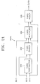
- FIG. 21 is a block diagram of the luminance compensator 204 of FIG. 14, according to a preferred embodiment 204A of the present invention, wherein the luminance compensator 204A consists of a third subtractor 300, a third divider 302, a third multiplier 304 and a first adder 306.
- the luminance compensator 204A shown in FIG. 21 serves to perform step 18A shown in FIG. 11.
- the third subtractor 300 subtracts an intensity level Xi of a channel Pi received through an input terminal IN14 from a maximum intensity level maxValue of each channel Pi of a color signal received through an input termial IN13, and outputs the subtracted result to the third divider 302.
- the third divider 302 divides the result subtracted by the third subtractor 300 by the maximum intensity level maxValue of each the channel Pi of the color signal received through the input terminal IN13, and outputs the divided result to the third multiplier 304.
- the third multiplier 304 multiplies the result divided by the third divider 302 by a luminance enhancing ratio B_inc received through an input terminal IN15 and the intensity level Xi received through the input terminal IN14, and outputs the multiplied result to the first adder 306.
- the first adder 306 adds the result multiplied by the third multiplier 304 with the intensity level Xi received through the input terminal IN14, and outputs the added result as a luminance-compressed result Pi' of the channel Pi through the output terminal OUT9.
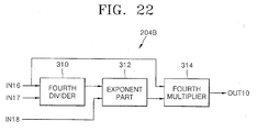
- FIG. 22 is a block diagram of the luminance compensator 204 of FIG. 14, according to another preferred embodiment 204B of the present invention, wherein the luminance compensator 204B consists of a fourth divider 310, an exponent part 312, and a fourth multiplier 314.
- the luminance compensator 204B shown in FIG. 22 serves to perform step 18B shown in FIG. 12.
- the fourth divider 310 divides an intensity level Xi of each channel Pi-of a color signal received through an input terminal IN 17 by a maximal intensity level maxValue of each channel Pi of a color signal received through an input terminal IN16, and outputs the divided result to the exponent part 312.
- the exponent part 312 calculates the luminance enhancing ratio (B_inc)-th power of the result divided by the fourth divider 310, wherein the luminance enhancing ratio B_inc is received from the luminance enhancing ratio calculator 202 through an input terminal 18, and outputs the calculated result to the fourth multiplier 314.
- the fourth multiplier 314 multiplies the maximum intensity level maxValue of each the channel Pi of the color signal received through the input terminal IN16 by the result calculated by the exponent part 312, and outputs the multiplied result as a luminance-compensated result Pi' of the channel Pi through an output terminal OUT10.
- FIG. 23 is a block diagram of the luminance compensator 204 of FIG. 14, according to still another preferred embodiment 204C of the present invention, wherein the luminance compensator 204C consists of a fourth subtractor 330, a fifth divider 332, a fifth multiplier 334 and a second adder 336.
- the luminance compensator 204C shown in FIG. 23 serves to perform step 18C shown in FIG. 13.
- the fourth subtractor 330 subtracts a maximum value MAX of intensity levels of a color signal received through an input terminal IN20 from a maximum intensity level maxValue of each channel Pi of a color signal received through an input terminal IN19, and outputs the subtracted result to the fifth divider 332.
- the fifth divider 332 divides the result subtracted by the fourth subtractor 330 by the maximum intensity level maxValue of each the channel Pi of the color signal received through the input terminal IN19, and outputs the divided result to the fifth multiplier 334.
- the fifth multiplier 334 multiplies the result divided by the fifth divider 332 by a luminance enhancing ratio B_inc received through an input terminal IN21 and the maximum value MAX received through the input terminal IN20, and outputs the multiplied result to the second adder 336.
- the second adder 336 adds the result multiplied by the fifth multiplier 334 with the maximum value MAX received through the input terminal IN20, and outputs the added result as a luminance-compensated result Pi' of the channel Pi through an output terminal OUT11.
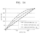
- FIG. 24 is a graph illustrating a relationship between the input color signal Pi and the output color signal Pi', wherein the horizontal axis of the graph represents an input color signal Pi given to the color signal luminance compensation method or apparatus according to the present invention and the vertical axis of the graph represents an output color signal Pi' obtained from the input color signal Pi by the color signal luminance compensation method or apparatus according to the present invention.
- a relationship between an input signal Pi and an output signal Pi' is linear.
- the output signal Pi' becomes greater near the middle level of the input signal Pi.
- the output signal Pi' has an intermediate value between the high saturation and the low saturation.
- the amplitude of the non-linear curve can be controlled by the first and/or second constants C2 and/or C3 provided in Equations 4 and/or 5.
- a luminance enhancing ratio is adjusted according to a saturation value of the color signal, the difference between the allowable luminance ratio and the predetermined value, or the result of dividing the allowable luminance value by the predetermined value, thereby reducing a luminance difference between a signal with a high saturation and a signal with a low saturation. That is, by increasing or decreasing the luminance of an input color signal in proportion to the saturation of the input color signal, it is possible to improve luminances of color signals with low or middle intensity levels and thereby avoid deterioration of picture quality.
Landscapes
- Engineering & Computer Science (AREA)
- Multimedia (AREA)
- Signal Processing (AREA)
- Physics & Mathematics (AREA)
- General Physics & Mathematics (AREA)
- Theoretical Computer Science (AREA)
- Processing Of Color Television Signals (AREA)
- Liquid Crystal Display Device Control (AREA)
- Television Receiver Circuits (AREA)
- Control Of Indicators Other Than Cathode Ray Tubes (AREA)
- Controls And Circuits For Display Device (AREA)
- Image Processing (AREA)
Applications Claiming Priority (2)
| Application Number | Priority Date | Filing Date | Title |
|---|---|---|---|
| KR1020030082771A KR100561852B1 (ko) | 2003-11-20 | 2003-11-20 | 색 신호의 밝기 보상 방법 및 장치 |
| KR2003082771 | 2003-11-20 |
Publications (2)
| Publication Number | Publication Date |
|---|---|
| EP1534019A2 true EP1534019A2 (de) | 2005-05-25 |
| EP1534019A3 EP1534019A3 (de) | 2006-09-06 |
Family
ID=34431804
Family Applications (1)
| Application Number | Title | Priority Date | Filing Date |
|---|---|---|---|
| EP04255658A Withdrawn EP1534019A3 (de) | 2003-11-20 | 2004-09-17 | Methode und Vorrichtung zur Kompensation der Luminanz eines Farbsignals |
Country Status (5)
| Country | Link |
|---|---|
| US (1) | US7450183B2 (de) |
| EP (1) | EP1534019A3 (de) |
| JP (1) | JP4002921B2 (de) |
| KR (1) | KR100561852B1 (de) |
| CN (1) | CN100401788C (de) |
Cited By (3)
| Publication number | Priority date | Publication date | Assignee | Title |
|---|---|---|---|---|
| US8055070B2 (en) | 2007-01-05 | 2011-11-08 | Geo Semiconductor Inc. | Color and geometry distortion correction system and method |
| US8442316B2 (en) | 2007-01-05 | 2013-05-14 | Geo Semiconductor Inc. | System and method for improving color and brightness uniformity of backlit LCD displays |
| US12243463B2 (en) | 2022-03-25 | 2025-03-04 | Samsung Display Co., Ltd. | Display device |
Families Citing this family (12)
| Publication number | Priority date | Publication date | Assignee | Title |
|---|---|---|---|---|
| KR100735283B1 (ko) * | 2005-09-29 | 2007-07-03 | 삼성전자주식회사 | 영상 보상 방법 |
| JP4622900B2 (ja) * | 2006-03-17 | 2011-02-02 | パナソニック株式会社 | 画像処理装置、画像処理方法、プログラムおよび記録媒体 |
| TW200830271A (en) * | 2007-01-04 | 2008-07-16 | Novatek Microelectronics Corp | Method and apparatus of color adjustment |
| KR101348369B1 (ko) | 2007-11-12 | 2014-01-07 | 삼성전자주식회사 | 디스플레이 장치의 색 변환 방법 및 장치 |
| US9196019B2 (en) * | 2008-03-13 | 2015-11-24 | Tp Vision Holding B.V. | Color image enhancement |
| JP2010211098A (ja) | 2009-03-12 | 2010-09-24 | Lg Display Co Ltd | 画像駆動方法 |
| KR101310921B1 (ko) * | 2009-12-29 | 2013-09-25 | 엘지디스플레이 주식회사 | 유기전계발광표시장치와 이의 구동방법 |
| KR102048925B1 (ko) * | 2012-12-28 | 2019-11-27 | 삼성디스플레이 주식회사 | 표시 장치 및 표시 장치의 구동 방법 |
| TW201503052A (zh) * | 2013-07-04 | 2015-01-16 | Novatek Microelectronics Corp | 影像處理裝置及應用其之影像處理方法 |
| CN107209927B (zh) * | 2014-09-19 | 2020-07-03 | 巴尔科股份有限公司 | 利用减少的视觉假象提高对比度的方法 |
| WO2016111362A1 (ja) * | 2015-01-09 | 2016-07-14 | シャープ株式会社 | 液晶表示装置、液晶表示装置の制御方法 |
| CN110459176A (zh) * | 2019-08-16 | 2019-11-15 | 合肥工业大学 | 一种amoled显示器的色域转换方法 |
Family Cites Families (13)
| Publication number | Priority date | Publication date | Assignee | Title |
|---|---|---|---|---|
| DE4106305A1 (de) | 1991-02-28 | 1992-09-03 | Broadcast Television Syst | Verfahren zur farbkorrektur eines videosignals |
| JPH11266369A (ja) * | 1998-03-17 | 1999-09-28 | Fuji Photo Film Co Ltd | 画像の明るさ調整方法および装置 |
| JP3492202B2 (ja) | 1998-06-24 | 2004-02-03 | キヤノン株式会社 | 画像処理方法、装置および記録媒体 |
| WO2000046983A1 (en) * | 1999-02-05 | 2000-08-10 | Koninklijke Philips Electronics N.V. | Histogram equalization |
| JP2002044679A (ja) | 2000-07-21 | 2002-02-08 | Olympus Optical Co Ltd | 映像信号処理回路 |
| US6726333B2 (en) * | 2001-02-09 | 2004-04-27 | Reflectivity, Inc | Projection display with multiply filtered light |
| DE50112268D1 (de) * | 2001-02-09 | 2007-05-10 | Imaging Solutions Ag | Digitale lokale Bildeigenschaftssteuerung mittels Masken |
| JP4145022B2 (ja) | 2001-05-10 | 2008-09-03 | 富士フイルム株式会社 | 輝度調整装置およびその動作制御方法 |
| US7268757B2 (en) | 2001-06-11 | 2007-09-11 | Genoa Color Technologies Ltd | Device, system and method for color display |
| JP3867586B2 (ja) * | 2002-01-29 | 2007-01-10 | 株式会社日立製作所 | 映像表示装置 |
| KR100418911B1 (ko) * | 2002-02-26 | 2004-02-14 | 엘지전자 주식회사 | 영상 표시기기의 밝기 차이 개선장치 및 그 방법 |
| AU2003278511A1 (en) * | 2002-11-27 | 2004-06-18 | Koninklijke Philips Electronics N.V. | Method of improving the perceptual contrast of displayed images |
| JP3801573B2 (ja) * | 2003-03-19 | 2006-07-26 | 松下電器産業株式会社 | プロジェクタ |
-
2003
- 2003-11-20 KR KR1020030082771A patent/KR100561852B1/ko not_active Expired - Fee Related
-
2004
- 2004-09-09 US US10/936,545 patent/US7450183B2/en active Active
- 2004-09-17 EP EP04255658A patent/EP1534019A3/de not_active Withdrawn
- 2004-09-20 CN CNB200410082534XA patent/CN100401788C/zh not_active Expired - Fee Related
- 2004-11-22 JP JP2004336933A patent/JP4002921B2/ja not_active Expired - Fee Related
Cited By (3)
| Publication number | Priority date | Publication date | Assignee | Title |
|---|---|---|---|---|
| US8055070B2 (en) | 2007-01-05 | 2011-11-08 | Geo Semiconductor Inc. | Color and geometry distortion correction system and method |
| US8442316B2 (en) | 2007-01-05 | 2013-05-14 | Geo Semiconductor Inc. | System and method for improving color and brightness uniformity of backlit LCD displays |
| US12243463B2 (en) | 2022-03-25 | 2025-03-04 | Samsung Display Co., Ltd. | Display device |
Also Published As
| Publication number | Publication date |
|---|---|
| JP4002921B2 (ja) | 2007-11-07 |
| CN1620151A (zh) | 2005-05-25 |
| US7450183B2 (en) | 2008-11-11 |
| KR20050049008A (ko) | 2005-05-25 |
| KR100561852B1 (ko) | 2006-03-16 |
| CN100401788C (zh) | 2008-07-09 |
| EP1534019A3 (de) | 2006-09-06 |
| JP2005160085A (ja) | 2005-06-16 |
| US20050110906A1 (en) | 2005-05-26 |
Similar Documents
| Publication | Publication Date | Title |
|---|---|---|
| EP1534019A2 (de) | Methode und Vorrichtung zur Kompensation der Luminanz eines Farbsignals | |
| US9350965B2 (en) | Apparatus and method of controlling brightness of image | |
| US7599551B2 (en) | Color correction device and color correction method | |
| JP5107355B2 (ja) | 入力色域よりも狭い再生色域への色域マッピングのための方法、装置、及び、プログラム | |
| JP3857991B2 (ja) | 映像の輝度変更方法及びその装置 | |
| KR101348369B1 (ko) | 디스플레이 장치의 색 변환 방법 및 장치 | |
| EP1747665B1 (de) | Verfahren zum bearbeiten von bilddaten | |
| US6343147B2 (en) | Print preview and setting background color in accordance with a gamma value, color temperature and illumination types | |
| EP0933952A2 (de) | Verfahren und Gerät zur Farbkonversion | |
| US20090060326A1 (en) | Image processing apparatus and method | |
| US20090009525A1 (en) | Color Adjustment Device and Method | |
| CA2143344A1 (en) | Method for enhancing detail in color signals and circuitry for implementing that method in color video equipment | |
| Chae et al. | A tone compression model for the compensation of white point shift generated from HDR rendering | |
| US7006104B2 (en) | Image correction method and system | |
| EP1600894B1 (de) | Apparat und Verfahren zum Korrigieren der Farbe eines Bildes | |
| US7760208B2 (en) | Non-linear picture processing | |
| JPH05244406A (ja) | 色調整装置 | |
| JPH0846989A (ja) | 色変換方法及びその装置 | |
| US7557953B2 (en) | Image processing device and image processing method | |
| KR100464323B1 (ko) | 영상의 밝기 변경 방법 및 장치 | |
| JP2005130273A (ja) | 画像処理装置及び画像処理方法 | |
| JPH1074256A (ja) | 彩度補正方法および彩度補正装置 | |
| JP2000341548A (ja) | 色域圧縮装置及び色域圧縮方法 |
Legal Events
| Date | Code | Title | Description |
|---|---|---|---|
| PUAI | Public reference made under article 153(3) epc to a published international application that has entered the european phase |
Free format text: ORIGINAL CODE: 0009012 |
|
| AK | Designated contracting states |
Kind code of ref document: A2 Designated state(s): AT BE BG CH CY CZ DE DK EE ES FI FR GB GR HU IE IT LI LU MC NL PL PT RO SE SI SK TR |
|
| AX | Request for extension of the european patent |
Extension state: AL HR LT LV MK |
|
| PUAL | Search report despatched |
Free format text: ORIGINAL CODE: 0009013 |
|
| AK | Designated contracting states |
Kind code of ref document: A3 Designated state(s): AT BE BG CH CY CZ DE DK EE ES FI FR GB GR HU IE IT LI LU MC NL PL PT RO SE SI SK TR |
|
| AX | Request for extension of the european patent |
Extension state: AL HR LT LV MK |
|
| RIC1 | Information provided on ipc code assigned before grant |
Ipc: H04N 9/77 20060101ALI20060801BHEP Ipc: H04N 1/60 20060101AFI20060801BHEP |
|
| 17P | Request for examination filed |
Effective date: 20061108 |
|
| 17Q | First examination report despatched |
Effective date: 20070216 |
|
| AKX | Designation fees paid |
Designated state(s): DE FR GB IT NL |
|
| STAA | Information on the status of an ep patent application or granted ep patent |
Free format text: STATUS: THE APPLICATION IS DEEMED TO BE WITHDRAWN |
|
| 18D | Application deemed to be withdrawn |
Effective date: 20090609 |