EP1533675B1 - Verfahren und Vorrichtung zur Erwärmung des Steuergases für einen pneumatischen Regler eines Gas-Druckregelgerätes - Google Patents
Verfahren und Vorrichtung zur Erwärmung des Steuergases für einen pneumatischen Regler eines Gas-Druckregelgerätes Download PDFInfo
- Publication number
- EP1533675B1 EP1533675B1 EP04027393A EP04027393A EP1533675B1 EP 1533675 B1 EP1533675 B1 EP 1533675B1 EP 04027393 A EP04027393 A EP 04027393A EP 04027393 A EP04027393 A EP 04027393A EP 1533675 B1 EP1533675 B1 EP 1533675B1
- Authority
- EP
- European Patent Office
- Prior art keywords
- gas
- set forth
- line
- swirl chamber
- pressure
- Prior art date
- Legal status (The legal status is an assumption and is not a legal conclusion. Google has not performed a legal analysis and makes no representation as to the accuracy of the status listed.)
- Expired - Lifetime
Links
- 238000010438 heat treatment Methods 0.000 title claims abstract description 22
- 238000000034 method Methods 0.000 title claims abstract description 10
- 230000000694 effects Effects 0.000 claims abstract description 8
- 238000005259 measurement Methods 0.000 claims description 4
- 230000001105 regulatory effect Effects 0.000 abstract description 2
- 239000007789 gas Substances 0.000 description 121
- 238000011144 upstream manufacturing Methods 0.000 description 9
- VNWKTOKETHGBQD-UHFFFAOYSA-N methane Chemical compound C VNWKTOKETHGBQD-UHFFFAOYSA-N 0.000 description 8
- 239000013078 crystal Substances 0.000 description 4
- 230000000630 rising effect Effects 0.000 description 4
- 230000015572 biosynthetic process Effects 0.000 description 3
- 230000008859 change Effects 0.000 description 3
- 238000001816 cooling Methods 0.000 description 3
- 230000009467 reduction Effects 0.000 description 3
- 230000008901 benefit Effects 0.000 description 1
- 239000003638 chemical reducing agent Substances 0.000 description 1
- 230000008878 coupling Effects 0.000 description 1
- 238000010168 coupling process Methods 0.000 description 1
- 238000005859 coupling reaction Methods 0.000 description 1
- 230000001419 dependent effect Effects 0.000 description 1
- 230000017525 heat dissipation Effects 0.000 description 1
- 150000004677 hydrates Chemical class 0.000 description 1
- 238000009413 insulation Methods 0.000 description 1
- 239000012528 membrane Substances 0.000 description 1
- 230000008569 process Effects 0.000 description 1
- 238000000926 separation method Methods 0.000 description 1
Images


Classifications
-
- F—MECHANICAL ENGINEERING; LIGHTING; HEATING; WEAPONS; BLASTING
- F24—HEATING; RANGES; VENTILATING
- F24V—COLLECTION, PRODUCTION OR USE OF HEAT NOT OTHERWISE PROVIDED FOR
- F24V99/00—Subject matter not provided for in other main groups of this subclass
-
- F—MECHANICAL ENGINEERING; LIGHTING; HEATING; WEAPONS; BLASTING
- F25—REFRIGERATION OR COOLING; COMBINED HEATING AND REFRIGERATION SYSTEMS; HEAT PUMP SYSTEMS; MANUFACTURE OR STORAGE OF ICE; LIQUEFACTION SOLIDIFICATION OF GASES
- F25B—REFRIGERATION MACHINES, PLANTS OR SYSTEMS; COMBINED HEATING AND REFRIGERATION SYSTEMS; HEAT PUMP SYSTEMS
- F25B9/00—Compression machines, plants or systems, in which the refrigerant is air or other gas of low boiling point
- F25B9/02—Compression machines, plants or systems, in which the refrigerant is air or other gas of low boiling point using Joule-Thompson effect; using vortex effect
- F25B9/04—Compression machines, plants or systems, in which the refrigerant is air or other gas of low boiling point using Joule-Thompson effect; using vortex effect using vortex effect
Definitions
- the invention relates to a method for heating the control gas for a pneumatic regulator of a gas pressure regulator and a device for heating the control gas in the input pressure line to a pneumatic regulator of a gas pressure regulator, in particular for carrying out the aforementioned method.
- gas pressure regulators are used in gas pressure regulating devices, which work with auxiliary energy, which is therefore associated with a pneumatic regulator.
- controller takes place correlating to the main actuator gas relaxation and thus the corresponding temperature reduction.
- controller takes place correlating to the main actuator gas relaxation and thus the corresponding temperature reduction.
- nozzles and flow channels are present in controller, which have a significantly higher susceptibility to clogging by methane crystals (hydrates) due to icing, as the actuator itself.
- the risk of icing exists when due to the tension of a Gas due to the Joule-Thomson effect, the temperature of the gas drops sharply. In this case, a temperature reduction of approx. 0.4 K is associated with a pressure reduction of 1 bar.
- an electric preheater is often integrated into the inlet pressure line of the regulator, which heats the gas flow leading to the regulator.
- the electrical preheating of the control gas in the input pressure line of the regulator ensures the functionality of the controller.
- this method is energy consuming and therefore expensive.
- the invention is therefore an object of the invention to provide a method and an apparatus of the type mentioned, with the preheating of the gas stream to the controller can be accomplished in a cheaper way.
- the object is achieved according to the method in that after the Ranque-Hilsch effect a tangential in a cylindrical vortex chamber gas in particular with supercritical pressure gradient is divided into two gas streams of different temperature, wherein the warmer of the two gas streams through a heat exchanger, the control gas heated the pneumatic regulator.
- Supercritical in this context means that the absolute gas pressure before entering the vortex chamber is about twice as high as the absolute pressure behind the vortex chamber.
- the device for heating the control gas in the inlet pressure line to the pneumatic regulator of a gas pressure regulator in particular for carrying out the method is characterized according to the invention by a housing having a cylindrical vortex chamber with an inlet for the tangential inflow of the inlet pressure gas with a pressure gradient, and at least one outlet for the hot and at least one further outlet for the cold gas, and a heat exchanger surrounding the vortex chamber to form a gap space, the gap space having at least one inlet opening for supplying a control gas stream and at least one outlet opening for the control gas for the pneumatic controller heated by the heat exchanger wherein the gap space is heated by the warm gas flow in the vortex chamber.
- This is advantageous Pressure gradient supercritical.
- the so-called Ranque effect arises in a vortex tube or in a Hilsch tube.
- a vortex is created around the tube axis, which is cold in the core and warm outside in the core.
- the cold gas is allowed to flow off next to the nozzle via a shutter; the warm portion flows out the other end of the tube.
- the inlet for the tangential inflow of the gas is arranged in the head region, ie at the upper end of the cylindrical vortex chamber, wherein the Warmgasauslass is provided in the foot region, that is at the opposite end to the inlet of the inlet pressure gas in the vortex chamber.
- the cold gas outlet is located in the end face of the cylindrical vortex chamber, which is arranged at the opposite end to the hot gas outlet.
- the cold gas outlet is located centrally in the end face of the cylindrical vortex chamber in order to be able to flow off the cold gas rising centrally in the vortex chamber.
- the Warmgasauslass is changeable by a throttle in its cross section, wherein a correlation between the introduced gas volume and the output through the cold gas outlet and the Warmgasauslass volume flow. Accordingly, the inlet for the input pressure gas in the vortex chamber is variable.
- this throttle has a cone projecting centrally with the tip into the vortex chamber, wherein the cone not only serves to change the cross section, but also influences the division of the gas flow into the cold and warm gas flow.
- the aperture on the cold gas side is variable in order to process different amounts of gas flowing into the vortex chamber.
- the gap has at least one inlet opening and at least one outlet opening for the control gas for the pneumatic regulator. It is essential that the entrance and the Outlet opening for the control gas are respectively arranged at the opposite ends of the cylindrical vortex chamber to sweep the largest possible area of the heat exchanger by the heated gas and to optimally exploit the temperature gradient in the vortex chamber, since the temperature of the gas in the region of the gasauslasses highest is.
- the invention also relates to the control of the supply of heated control gas to the controller.
- a valve is arranged in particular in the line to the inlet into the vortex chamber. It is advantageous if the valve opens the inlet for the inlet pressure gas into the vortex chamber before the pneumatic controller requests control gas. This means that the device for heating the control gas receives a certain flow in order to supply the regulator from the beginning with hot gas.
- a shut-off valve is arranged in the line to the inlet into the vortex chamber. This shut-off valve is operated manually, that is, whenever the regulator is activated, the shut-off valve is opened.
- a pneumatic control valve is connected in the line to the inlet to the vortex chamber.
- the target pressure for opening the control valve is higher than the desired value of the pressure of the pneumatic regulator of the gas pressure control system.
- a switching valve is arranged in the line to the inlet in the vortex chamber. This switching valve is activated when the actuating pressure of the pneumatic regulator begins to change.
- the switching valve is designed so that it through the signal pressure is opened before the gas pressure regulator is put into operation by the pneumatic regulator.
- the housing is formed in two parts with a housing head and a housing sump, housing head and housing sump are thermally separated to prevent cooling of the fuselage through the head, which has the Kaltgasabströmtechnisch. It has been found that the function of the device is not guaranteed when the hull is frozen.
- the housing body has an axially extending second gap space, which is arranged approximately semicircular in the housing body. At the lower end it is connected to the warm gas outlet, at the upper end it flows into a line leading to the cold gas line.
- the input gas supplied to the switching valve is heated by the housing, as it comes in the switching valve to a gas relaxation with the risk of icing. Such icing is prevented when heated gas is supplied to the switching valve.
- FIG. 1 shows the basic principle of a vortex tube or called Hilsch tube;
- the tangential inflow of the gas is characterized by the arrow 1 in the cylindrical vortex chamber 30 can be seen, wherein the tangential incoming gas stream in an outer gas stream, characterized by the arrows 3, and an inner rising gas stream, characterized by the arrows 4, divides.
- the rising internal cold gas flow, characterized by the arrows 4 is led out of the vortex tube 2, corresponding to the arrow 5, whereas the hot gas component is led out of the vortex tube according to the arrow 6.
- the cone designated 51 promotes the division of the introduced tangential gas flow in the cold gas and the warm gas stream.
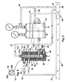
- FIGS. 2 to 4 Illustrations shown show both the device 10 for heating the control gas, as well as the pneumatic regulator 15 and the actuator 40 as part of the gas pressure control system.
- FIGS. 2 to 4 shown circuits differ essentially only by the arrangement of a shut-off valve in the input pressure line ( Fig. 2 ), a control valve ( Fig. 3 ) or a switching valve in the inlet pressure line ( Fig. 4 ).
- the housing sump 11b is thermally separated from the housing head 11a by an air gap 11c or other insulation. This is because a lot of heat is removed from the housing by the cold gas outflow line 27.
- the thermal separation is provided, for example, in the form of an air gap 11c.
- a device for heating the control gas with an upstream shut-off valve 25 is shown.
- the inlet pressure line 22 is the shut-off valve 25, by means of which the volume of the gas flow is controlled in the cylindrical vortex chamber 30 of the housing 11 .
- the tangential to the cylindrical vortex chamber 30 through the inlet pressure line 22 gas stream is divided according to the description Fig. 1 in a centrally rising cold gas stream 4 and a concentrically discharged hot gas stream 5 on.
- the cold gas stream 4 is supplied through the cold gas outlet 27a and the cold gas outflow 27 of the main line 20 behind the actuator 40.
- the throttle 50 comprises an adjustable cone 51 which, in cooperation with the cylindrical shell 32 of the swirl chamber 30, forms a gap 52 through which the concentrically guided warm gas is supplied through the outlet 35a through the warm gas outflow line 35 to the main line 20 after the actuator 40.
- the vortex chamber 30 is formed radially by the cylindrical shell 32; this cylindrical jacket 32 in conjunction with the gap 33 is part of the heat exchanger 34.
- the inlet opening 23a through the Steuergaszuströmtechnisch 23 Through the inlet opening 23a through the Steuergaszuströmtechnisch 23, the supply of the control gas into the gap 33.
- the wall 32 of the heat exchanger 34 is heated by the hot gas stream 5.
- the control gas flowing through the line 23 into the gap space 33 is heated in the gap space 33 by the warm gas flow 5 in the vortex chamber and is finally fed through the outlet opening 37a through the control gas discharge line 37 to the regulator 15.
- controller 15 a splitting of the supplied through the control gas discharge line 37 heated control gas takes place insofar as a portion of the gas flow through the control pressure line 41 is supplied to the actuator 40, wherein the remaining part of the controller 15 supplied control gas through the discharge line 42 of the main line 20 behind the actuator 40 is supplied.
- the controller 15 itself is connected by a measuring line 43 to the main line 20 behind the actuator 40.
- the operation of the device for heating the control gas is now such that before starting the regulator, the shut-off valve 25 is opened, with the result that the controller 15 is supplied with warm control gas, so as to prevent the formation of methane crystals in the controller 15 when working of the actuator and thus a gas relaxation.
- the hot gas line 35 is guided as a double tube around the Kaltgasabströmtechnisch to heat the Kaltgasabströmtechnisch from the outside.
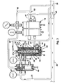
- the circuit according to Fig. 3 differs essentially from the according to Fig. 2 only by the connection of a control valve 60 in the input pressure line 22.
- a control valve 60 in the input pressure line 22.
- the same objects shown also bear the same reference numerals.
- the control valve 60 connected upstream of the device 10 for heating the control gas is set to a nominal value which is slightly higher than the set value of the pneumatic regulator 15.
- the valve 67 integrated therein opens takes the device 10 in operation. If now the output pressure continues to drop and the pneumatic regulator 15 is activated, it is supplied with the supplied through the line 37 to the controller heated control gas.
- the upstream control valve 60 is now fully open; the upstream of the pressure reducer 60 in line 21 pending inlet pressure is passed in full height in the cylindrical vortex chamber 30. In the case of complete shutdown of the pressure control system, the system runs to a closing pressure, which is determined by the upstream control valve 60.
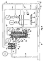
- the representation of the circuit according to Fig. 4 differs from the according to Fig. 2 or 3 in that the device 10 for heating the control gas, the switching valve 70 is connected upstream. Also in terms of the Representation according to Fig. 4 applies that same objects have the same reference numerals as in the Fig. 2 and 3 exhibit.
- the device 10 is preceded by the switching valve 70.
- This switching valve 70 is driven by a beginning change in control pressure of the pneumatic regulator 15 by the pressure in the control pressure line 41.
- the drive 71 of the switching valve 70 is acted on the closing side 72 from the outlet pressure in the main line 20 behind the actuator 40 and the force of the closing spring 73.
- the opening side 74 of the drive 71 of the switching valve 70 is connected by the control pressure line 41 to the pneumatic controller 15 in connection. If the gas pressure regulator is out of operation, the pressure in the control pressure line 41 is equal to the outlet pressure, d. H. the pressure in the main line 20 behind the actuator 40.
- the actuator 76 in the switching valve 70 is closed by the force of the closing spring 73.
- Starting Stelldruckup opens the actuator 76 in the switching valve 70 and takes the device for heating the control gas in operation.
- the switching valve 70 is designed so that it is opened by the control pressure before the actual gas pressure control device is put into operation via the pneumatic regulator 15.
- the expanded gas will reach a temperature resulting from the Joule-Thomson effect.
- the measurement of the output pressure for the pneumatic controller 15 via the line 43. In order therefore to occur at the measuring point 27 no icing, the control gas flowing through the line 42 from the controller 15 is discharged through this measuring line 43.
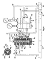
- FIGS. 6 and 7 show an embodiment according to FIG. 2 in which the hot gas emerging from the outlet 35a is still used for heating the housing body 11b. That is, the according to FIG. 2 arranged in the foot area hot gas line 35 is located in the embodiment according to the FIGS. 6 and 7 immediately below the Housing head 11a as a hot gas line 35b.
- an axially extending second gap space 12 is provided, which extends over a part of the lateral surface of the housing sump 11b. That is, the gap space is approximately semicircular in shape, so that the largest possible surface for heat dissipation exists ( FIG. 7 ). It has been found that this also the icing of the housing 11, and in particular of the housing body 11 b, can be avoided.
- the gas supplied to the switching valve 70 through the pipe 21 is heated in the casing of the swirl chamber 30.
- the gas is branched off with the inlet pressure in the line 23 in the line 26, passed through the housing bottom 11 b, and then to reach the switching valve 70, as already in connection with FIG. 4 has been described.
- the background to this is that the incoming gas in the switching valve relaxes, and as a result icing can occur as a result. This counteracts the supply of heated gas.
Landscapes
- Engineering & Computer Science (AREA)
- Physics & Mathematics (AREA)
- Thermal Sciences (AREA)
- Mechanical Engineering (AREA)
- General Engineering & Computer Science (AREA)
- Chemical & Material Sciences (AREA)
- Combustion & Propulsion (AREA)
- Filling Or Discharging Of Gas Storage Vessels (AREA)
- Details Of Valves (AREA)
- Control Of Fluid Pressure (AREA)
- Fluid-Driven Valves (AREA)
Description
- Die Erfindung betrifft ein Verfahren zur Erwärmung des Steuergases für einen pneumatischen Regler eines Gas-Druckregelgerätes sowie eine Vorrichtung zur Erwärmung des Steuergases in der Eingangsdruckleitung zu einem pneumatischen Regler eines Gas-Druckregelgerätes, insbesondere zur Durchführung des vorgenannten Verfahrens.
- Aus der
DE 950 295 ist bekannt, eine Kühleinrichtung mittels eines Ranque-Rohres zu betreiben. Hierbei wird der Wärmegasstrom aus dem Ranque-Rohr einer Heizung zugeführt, danach wird der erwärmte Lufstrom in ein Düsenverdichtersystem zur Bildung eines kalten Luftstrom entspannt, dieser kalte Lufstrom dem Ranque-Rohr zugeführt und von dort wird der Kaltlufstrom an einen Kühler übergeben. DieUS-A-4245665 zeigt einen Wärmetauscher, der nach dem Gegenstromprinzip arbeitet. - Häufig werden in Gas-Druckregelantagen Gas-Druckregelgeräte eingesetzt, die mit Hilfsenergie arbeiten, denen also ein pneumatischer Regler zugeordnet ist. Im Regler erfolgt eine zu dem Hauptstellglied korrelierende Gasentspannung und damit auch die entsprechende Temperaturabsenkung. Anders als beim Stellgerät sind allerdings in Regler relativ kleine Düsen und Strömungskanäle vorhanden, die eine deutlich höhere Anfälligkeit bezüglich des Verstopfens durch Methankristalle (Hydrate) aufgrund von Vereisung aufweisen, als das Stellgerät selbst. Die Gefahr der Vereisung besteht dann, wenn aufgrund der Enstpannung eines Gases sich aufgrund des Joule-Thomson-Effekts die Temperatur des Gases stark absenkt. Hierbei gilt, dass mit einer Druckabsenkung von 1 bar eine Temperaturabsenkung um ca. 0,4 K verbunden ist. Unterschreitet die Gastemperatur hinter dem Enstspannungsorgan den Taupunkt des Gases, können sich Methankristalle bilden, die die Funktion insbesondere des Reglers stören. Es besteht allerdings nicht nur die Gefahr der bereits zuvor genannten Verstopfung der Düsen bzw. der Strömungskanäle im Regler, vielmehr bewirkt eine starke Abkühlung des Gases, und damit der Bauteile, auch einen negativen Einfluss auf das Elastizitätsverhalten der Vergleichermenbranen. Dies ist gleichbedeutend mit unerwünschten größeren Regelabweichungen.
- Um den oben gennanten Nachteilen zu begegnen, wird vielfach in die Eingangsdruckleitung der Reglers ein elektrischer Vorwärmer integriert, der den zum Regler führenden Gasstrom aufheizt. Die elektrische Vorwärmung des Steuergases in der Eingangsdruckleitung des Reglers stellt die Funktionstüchtigkeit des Reglers sicher. Allerdings ist dieses Verfahren energieaufwändig und damit teuer.
- Der Erfindung liegt daher die Aufgabe zugrunde, ein Verfahren und eine Vorrichtung der eingangs genannten Art zu schaffen, mit der die Vorwärmung des Gasstromes zum Regelgerät hin auf preiswertere Weise bewerkstelligt werden kann.
- Die Aufgabe wird erfindungsgemäß entsprechend dem Verfahren dadurch gelöst, dass nach dem Ranque-Hilsch-Effekt ein in eine zylindrische Wirbelkammer tangential einströmendes Gas insbesondere mit überkritischem Druckgefälle sich in zwei Gasströme unterschiedlicher Temperatur aufteilt, wobei der wärmere der beiden Gasströme durch einen Wärmetauscher das Steuergas für den pneumatischen Regler erwärmt. Überkritisch bedeutet in diesem Zusammenhang, dass der absolute Gasdruck vor dem Einlass in die Wirbelkammer etwa doppelt so hoch ist, wie der absolute Druck hinter der Wirbelkammer.
- Die Vorrichtung zur Erwärmung des Steuergases in der Eingangsdruckleitung zu dem pneumatischen Regler eines Gas-Druckregelgerätes, insbesondere zur Durchführung des Verfahrens zeichnet sich erfindungsgemäß durch ein Gehäuse mit einer zylindrischen Wirbelkammer mit einem Einlass zum tangentialen Einströmen des Eingangsdruckgases mit einem Druckgefälle aus, und mindestens einem Auslass für das Warm- und mindestens einem weiteren Auslass für das Kaltgas, sowie einem die Wirbelkammer unter Bildung eines Spaltraumes umgebenden Wärmetauschers, wobei der Spaltraum mindestens eine Eingangsöffnung für die Zuführung eines Steuergasstromes und mindestens eine Ausgangsöffnung für das durch den Wärmetauscher erwärmte Steuergas für den pneumatischen Regler aufweist, wobei der Spaltraum durch den Warmgasstrom in der Wirbelkammer erwärmt wird. Vorteilhaft ist das Druckgefälle überkritisch. Der sogenannte Ranque-Effekt entsteht in einem Wirbelrohr bzw. in einem Hilsch-Rohr. In einem Rohr, in das durch eine Düse tangential Luft oder ein anderes Gas unter einem Druck von einigen bar geblasen wird, entsteht ein Wirbel um die Rohrachse, der im Kern kalt und außen warm ist. Das kalte Gas lässt man neben der Düse über eine Blende abströmen; der warme Anteil entströmt dem anderen Ende des Rohres. Durch die Ausnutzung des Ranque-Effektes unter Verwendung des Hilsch-Rohres lässt sich somit ein warmer Gasstrom erzeugen, der dem Regler über die Eingangsdruckleitung zugeführt wird, und der im Regler zuverlässig die Bildung von Methan-Kristallen verhindert und darüber hinaus den Regler auf Betriebstemperatur hält.
- Weitere vorteilhafte Merkmale und Varianten sind den Unteransprüchen zu entnehmen.
- Im Einzelnen ist vorgesehen, dass der Einlass zum tangentialen Einströmen des Gases im Kopfbereich, also am oberen Ende der zylindrischen Wirbelkammer angeordnet ist, wobei der Warmgasauslass im Fußbereich, das heißt am entgegengesetzten Ende zu dem Einlass des Eingangsdruckgases in der Wirbelkammer vorgesehen ist. Hierbei ist weiterhin vorgesehen, dass sich der Kaltgasauslass in der Stirnseite der zylindrischen Wirbelkammer befindet, die am entgegengesetzten Ende zu dem Warmgasauslass angeordnet ist. Hierbei ist weiterhin vorgesehen, dass sich der Kaltgasauslass zentrisch in der Stirnseite der zylindrischen Wirbelkammer befindet, um das mittig in der Wirbelkammer aufsteigende Kaltgas abströmen zu können.
- Nach einem weiteren Merkmal der Erfindung ist der Warmgasauslass durch eine Drossel in seinem Querschnitt veränderbar, wobei eine Korrelation zwischen dem eingeführten Gasvolumen und dem durch den Kaltgasauslass und dem Warmgasauslass abgegebenen Volumenstrom besteht. Entsprechend ist auch der Einlass für das Eingangsdruckgas in die Wirbelkammer veränderlich.
- Im Einzelnen weist diese Drossel einen mit der Spitze mittig in die Wirbelkammer ragenden Konus auf, wobei der Konus nicht nur der Veränderung des Querschnitts dient, sondern darüber hinaus auch die Aufteilung des Gasstromes in den Kalt- und den Warmgasstrom beeinflusst. Auch die Blende auf der Kaltgasseite ist veränderlich, um unterschiedliche in die Wirbelkammer einströmende Gasmengen verarbeiten zu können.
- Wie bereits an anderer Stelle erörtert, besitzt der Spaltraum mindestens eine Eingangsöffnung und mindestens eine Ausgangsöffnung für das Steuergas für den pneumatischen Regler. Wesentlich ist, dass die Eingangs- und die Ausgangsöffnung für das Steuergas jeweils an den entgegengesetzten Enden der zylindrischen Wirbelkammer angeordnet sind, um eine möglichst große Fläche des Wärmetauschers durch das erwärmte Gas überstreichen zu lassen und um das Temperaturgefälle in der Wirbelkammer optimal auszunutzen, da die Temperatur des Gases im Bereich des Wärmegasauslasses am höchsten ist.
- Gegenstand der Erfindung ist ebenfalls die Steuerung der Zufuhr von erwärmtem Steuergas zum Regler. Insofern ist insbesondere in der Leitung zu dem Einlass in die Wirbelkammer ein Ventil angeordnet. Vorteilhaft ist, wenn durch das Ventil der Einlass für das Eingangsdruckgas in die Wirbelkammer geöffnet wird, bevor der pneumatische Regler Steuergas anfordert. Das heißt, dass die Vorrichtung zur Erwärmung des Steuergases einen gewissen Vorlauf erhält, um den Regler von Beginn an mit Warmgas zu versorgen.
- Nach einer ersten Variante ist vorgesehen, dass in der Leitung zu dem Einlass in die Wirbelkammer ein Absperrventil angeordnet ist. Dieses Absperrventil wird händisch betätigt, das heißt, dass immer dann, wenn der Regler aktiviert wird, das Absperrventil geöffnet wird.
- In einer anderen zweiten Variante ist in der Leitung zu dem Einlass in die Wirbelkammer ein pneumatisches Steuerventil angeschlossen. Um eben jenen Vorlauf der Vorrichtung zur Erwärmung des Steuergases zu gewährleisten, ist der Solldruck zum Öffnen des Steuerventils höher, als der Sollwert des Druckes des pneumatischen Reglers der Gas-Druckregelanlage.
- Nach einer weiteren dritten Variante ist in der Leitung zu dem Einlass in die Wirbelkammer ein Schaltventil angeordnet. Dieses Schaltventil wird bei beginnender Änderung des Stelldrucks des pneumatischen Reglers angesteuert. Das heißt, dass das Schaltventil so ausgelegt ist, dass es durch den Stelldruck geöffnet wird, bevor das Gas-Druckregelgerät durch den pneumatischen Regler in Betrieb genommen wird. Dies hat den Vorteil, dass die Vorrichtung zur Erwärmung des Steuergases automatisch mit ihrer Tätigkeit beginnt, und dass Sollwertänderungen an dem pneumatischen Regler keine Nachjustierung des Sollwertes an dem vorgeschalteten Steuerventil erforderlich machen, wie dies bei der Variante zwei der Fall ist, so dass der Schließdruck der Anlage ausschließlich vom pneumatischen Regler bestimmt wird.
- Vorteilhaft ist weiterhin, wenn das Gehäuse zweiteilig mit einem Gehäusekopf und einem Gehäuserumpf ausgebildet ist, wobei Gehäusekopf und Gehäuserumpf thermisch getrennt sind, um eine Abkühlung des Rumpfes durch den Kopf, der die Kaltgasabströmleitung aufweist, zu verhindern. Es hat sich nämlich herausgestellt, dass bei vereisendem Rumpf die Funktion der Vorrichtung nicht gewährleistet ist.
- Weiterhin ist vorteilhaft, wenn das durch den Warmgasauslass abströmende Gas noch zur Erwärmung des Gehäuserumpfes verwendet wird. Hierbei weist der Gehäuserumpf einen sich axial erstreckenden zweiten Spaltraum auf, der in etwa halbkreisförmig im Gehäuserumpf angeordnet ist. Am unteren Ende ist er mit dem Warmgasauslass verbunden, am oberen Ende mündet er in eine Leitung, die zur Kaltgasleitung führt.
- Weiterhin ist vorgesehen, dass auch das dem Schaltventil zugeführte Eingangsgas durch das Gehäuse erwärmt wird, da es auch im Schaltventil zu einer Gasentspannung mit der Gefahr der Vereisung kommt. Einer solchen Vereisung wird vorgebeugt, wenn dem Schaltventil erwärmtes Gas zugeführt wird.
- Anhand der Zeichnungen wird die Erfindung nachstehend beispielhaft näher erläutert.
- Fig. 1
- veranschaulicht das Grundprinzip eines Wirbelrohres bzw. einer Wirbelkammer;
- Fig. 2
- zeigt die Vorrichtung zur Erwärmung des Gases in der Kopplung mit einem pneumatischen Regler und einem der Vorrichtung vorgeschalteten Absperrventil,
- Fig. 3
- zeigt eine Vorrichtung gemäß
Fig. 1 , wobei der Vorrichtung selbst ein pneumatisches Steuerventil vorgeschaltet ist; - Fig. 4
- zeigt die Vorrichtung gemäß
Fig. 2 mit einem der Vorrichtung vorgeschalteten Schaltventil.; - Fig. 5
- zeigt die Einzelheit "X" aus
Fig. 2 in einer Draufsicht; - Fig. 6
- zeigt eine Vorrichtung entsprechend
Fig. 2 , bei der das Gehäuse einen zweiten Spaltraum aufweist; - Fig. 7
- zeigt einen Schnitt gemäß der Linie VII - VII aus
Fig. 6 ; - Fig. 8
- zeigt eine Vorrichtung entsprechend
Fig. 4 , bei der das Gas mit dem Eingangsdruck für das Schaltventil durch das Gehäuse vorgewärmt wird. -
Figur 1 zeigt das Grundprinzip eines Wirbelrohres bzw. auch Hilsch-Rohr genannt; hierbei ist die tangentiale Einströmung des Gases gekennzeichnet durch den Pfeil 1 in die zylindrische Wirbelkammer 30 erkennbar, wobei sich der tangential einströmende Gasstrom in einen äußeren Gasstrom, gekennzeichnet durch die Pfeile 3, und einen inneren aufsteigenden Gasstrom, gekennzeichnet durch die Pfeile 4, aufteilt. Der aufsteigende innere kalte Gasstrom, gekennzeichnet durch die Pfeile 4, wird aus dem Wirbelrohr 2, entsprechend dem Pfeil 5 herausgeführt, wohingegen der Warmgasanteil aus dem Wirbelrohr entsprechend dem Pfeil 6 herausgeführt wird. Der mit 51 bezeichnete Kegel fördert die Aufteilung des eingeführten tangentialen Gasstromes in den Kaltgas- und den Warmgasstrom. - Die in den
Figuren 2 bis 4 gezeigten Darstellungen zeigen sowohl die Vorrichtung 10 zur Erwärmung des Steuergases, als auch den pneumatischen Regler 15 und das Stellgerät 40 als Bestandteil der Gas-Druckregelanlage. - Die in den
Figuren 2 bis 4 dargestellten Schaltungen unterscheiden sich im Wesentlichen nur durch die Anordnung eines Absperrventils in der Eingangsdruckleitung (Fig. 2 ), eines Steuerventils (Fig. 3 ) oder eines Schaltventils in der Eingangsdruckleitung (Fig. 4 ). - Bei der Darstellung gemäß den
Figuren 2 bis 8 ist darüber hinaus erkennbar, dass der Gehäuserumpf 11b vom Gehäusekopf 11a durch einen Luftspalt 11c oder eine andere Isolierung thermisch getrennt ist. Dies deshalb, weil durch die Kaltgasabströmleitung 27 dem Gehäuse sehr viel Wärme entzogen wird. Um nun zu verhindern, dass der Wärmeabgang sich auf den Gehäuserumpf überträgt, ist die thermische Trennung beispielsweise in Form eines Luftspaltes 11c vorgesehen. - Gemäß
Fig. 2 ist eine Vorrichtung zur Erwärmung des Steuergases mit einem vorgeschalteten Absperrventil 25 gezeigt. Von der Hauptleitung 20 zweigt eine Leitung 21 ab, die sich aufspaltet in die sogenannte Eingangsdruckleitung 22 und die Steuergaszuströmleitung 23. In der Eingangsdruckleitung 22 befindet sich das Absperrventil 25, mit Hilfe dessen das Volumen des Gasstroms in die zylindrische Wirbelkammer 30 des Gehäuses 11 gesteuert wird. Der in die zylindrische Wirbelkammer 30 durch die Eingangsdruckleitung 22 tangential einströmende Gasstrom teilt sich entsprechend der Beschreibung zuFig. 1 in einen mittig aufsteigenden Kaltgasstrom 4 und einen konzentrisch abgeführten Warmgasstrom 5 auf. Der Kaltgasstrom 4 wird durch den Kaltgasauslass 27a und die Kaltgasabströmleitung 27 der Hauptleitung 20 hinter dem Stellgerät 40 zugeführt. Die Ausbildung bzw. auch Anordnung der beiden Einlässe 22a der Eingangsdruckleitung 22 in die zylindrische Wirbelkammer 30 ergibt sich aus derFig. 5 als Einzelheit "X" zu derFig. 2 . Dort ist erkennbar, dass die Einlässe 22a jeweils derart angeordnet sind, dass das Gas tangential in die zylindrische Wirbelkammer 30 einströmt. - Am unteren Ende, d. h. im Fußbereich der zylindrischen Wirbelkammer 30 befindet sich die insgesamt mit 50 bezeichnete Drossel. Die Drossel 50 umfasst einen verstellbaren Kegel 51, der in Zusammenarbeit mit dem zylindrischen Mantel 32 der Wirbelkammer 30 einen Spalt 52 bildet, durch den das konzentrisch geführte Warmgas durch den Auslass 35a durch die Warmgasabströmleitung 35 wiederum der Hauptleitung 20 nach dem Stellgerät 40 zugeführt wird.
- Die Wirbelkammer 30 wird radial durch den zylindrischen Mantel 32 gebildet; dieser zylindrische Mantel 32 in Verbindung mit dem Spaltraum 33 ist Teil des Wärmetauschers 34. Durch die Eingangsöffnung 23a erfolgt durch die Steuergaszuströmleitung 23 die Zuführung des Steuergases in den Spaltraum 33. Die Wandung 32 des Wärmetauschers 34 wird durch den Warmgasstrom 5 erwärmt. Das durch die Leitung 23 in den Spaltraum 33 einströmende Steuergas wird im Spaltraum 33 durch den Warmgasstrom 5 in der Wirbelkammer erwärmt und wird letzthin durch die Ausgangsöffnung 37a durch die Steuergasabströmleitung 37 dem Regler 15 zugeführt. Im Regler 15 findet eine Aufspaltung des durch die Steuergasabströmleitung 37 zugeführten erwärmten Steuergases insofern statt, als ein Teil des Gasstromes durch die Stelldruckleitung 41 dem Stellgerät 40 zugeführt wird, wobei der übrige Teil des dem Regler 15 zugeführten Steuergases durch die Abströmleitung 42 der Hauptleitung 20 hinter dem Stellgerät 40 zugeführt wird. Der Regler 15 selbst ist durch eine Messleitung 43 mit der Hauptleitung 20 hinter dem Stellgerät 40 verbunden.
- Die Funktionsweise der Vorrichtung zur Erwärmung des Steuergases ist nun derart, dass vor Inbetriebnahme des Reglers das Absperrventil 25 geöffnet wird, mit der Folge, dass der Regler 15 mit warmen Steuergas versorgt wird, um so bei Arbeit des Stellgerätes und mithin einer Gasentspannung eine Bildung von Methankristallen im Regler 15 zu verhindern.
Um eine Vereisung auch in der Kaltgasabströmleitung 27 zu verhindern, ist nach einem Merkmal der Erfindung die Warmgasleitung 35 als doppeltes Rohr um die Kaltgasabströmleitung geführt, um die Kaltgasabströmleitung von außen zu erwärmen. - Die Schaltung gemäß
Fig. 3 unterscheidet sich im Wesentlichen von der gemäßFig. 2 lediglich durch die Vorschaltung eines Steuerventils 60 in die Eingangsdruckleitung 22. In denFig. 2 und3 dargestellte gleiche Gegenstände tragen auch die gleichen Bezugszeichen. - Die Funktionsweise der Schaltung gemäß
Fig. 3 ist nun wie folgt: - Das der Vorrichtung 10 zur Erwärmung des Steuergases vorgeschaltete Steuerventil 60 ist auf einen Sollwert eingestellt, der geringfügig höher ist, als der Sollwert des pneumatischen Reglers 15. Sobald der Ausgangsdruck auf den Sollwert dieses Steuerventil 60 abgesunken ist, öffnet sich das darin integrierte Ventil 67 und nimmt die Vorrichtung 10 in Betrieb. Wenn jetzt der Ausgangsdruck weiter absinkt und den pneumatische Regler 15 in Funktion nimmt, wird dieser mit dem durch die Leitung 37 dem Regler zugeführten aufgeheizten Steuergas versorgt. Das vorgeschaltete Steuerventil 60 ist jetzt voll geöffnet; der vor dem Druckminderer 60 in der Leitung 21 anstehende Eingangsdruck wird in voller Höhe in die zylindrische Wirbelkammer 30 geleitet. Bei völligem Außerbetriebgehen der Druckregelanlage läuft das System auf einen Schließdruck, der vom vorgeschalteten Steuerventil 60 bestimmt wird.
- Die Darstellung der Schaltung gemäß
Fig. 4 unterscheidet sich von der gemäßFig. 2 bzw. 3 dadurch, dass der Vorrichtung 10 zur Erwärmung des Steuergases das Schaltventil 70 vorgeschaltet ist. Auch in Bezug auf die Darstellung gemäßFig. 4 gilt, dass gleiche Gegenstände gleiche Bezugszeichen wie in denFig. 2 und3 aufweisen. - Wie bereits erläutert, ist der Vorrichtung 10 das Schaltventil 70 vorgeschaltet. Dieses Schaltventil 70 wird von einer beginnenden Stelldruckänderung des pneumatischen Reglers 15 durch den Druck in der Stelldruckleitung 41 angesteuert. Der Antrieb 71 des Schaltventils 70 wird auf der Schließseite 72 vom Ausgangsdruck in der Hauptleitung 20 hinter dem Stellgerät 40 und von der Kraft der Schließfeder 73 beaufschlagt. Die Öffnungsseite 74 des Antriebes 71 des Schaltventils 70 steht durch die Stelldruckleitung 41 mit dem pneumatischen Regler 15 in Verbindung. Ist das Gasdruckregelgerät außer Betrieb, wird der Druck in der Stelldruckleitung 41 gleich dem Ausgangsdruck, d. h. dem Druck in der Hauptleitung 20 hinter dem Stellgerät 40. Das Stellglied 76 im Schaltventil 70 wird durch die Kraft der Schließfeder 73 geschlossen. Beginnender Stelldruckaufbau öffnet das Stellglied 76 im Schaltventil 70 und nimmt die Vorrichtung zur Erwärmung des Steuergases in Funktion. Dabei ist das Schaltventil 70 so ausgelegt, dass es durch den Stelldruck geöffnet wird, bevor das eigentliche Gas-Druckregelgerät über den pneumatischen Regler 15 in Betrieb genommen wird.
- In der Hauptleitung 20 nach dem Stellgerät 40 wird das entspannte Gas eine Temperatur erreichen, die sich aus dem Joule-Thomson-Effekt ergibt. Die Messung des Ausgangsdruckes für den pneumatischen Regler 15 erfolgt über die Leitung 43. Um am Messpunkt 27 demzufolge keine Vereisung eintreten zu lassen, wird das vom Regler 15 durch die Leitung 42 abströmende Steuergas durch diese Messleitung 43 abgeführt.
- Die
Figuren 6 und 7 zeigen eine Ausführungsform gemäßFigur 2 , bei der das aus dem Auslass 35a austretende Warmgas noch zur Erwärmung des Gehäuserumpfes 11 b Verwendung findet. Das heißt, die gemäßFigur 2 im Fußbereich angeordnete Warmgasleitung 35 befindet sich bei der Ausführungsform gemäß denFiguren 6 und 7 unmittelbar unter dem Gehäusekopf 11a als Warmgasleitung 35b. Zur Erwärmung des Gehäuserumpfes als Verbindung zwischen Auslass 35a und der Warmgasleitung 35b ist ein sich axial erstreckender zweiter Spaltraum 12 vorgesehen, der sich über einen Teil der Mantelfläche des Gehäuserumpfes 11b erstreckt. Das heißt, der Spaltraum ist in etwa halbkreisförmig getroffen, so dass eine möglichst große Oberfläche zur Wärmeabgabe besteht (Figur 7 ). Es hat sich herausgestellt, dass hierdurch auch die Vereisung des Gehäuses 11, und hier insbesondere des Gehäuserumpfes 11b, vermieden werden kann. - Bei der Ausführungsform gemäß
Figur 8 wird das dem Schaltventil 70 durch die Leitung 21 zugeführte Gas in dem Gehäuse der Wirbelkammer 30 erwärmt. Hierzu wird das Gas mit dem Eingangsdruck in der Leitung 23 in die Leitung 26 abgezweigt, durch den Gehäuserumpf 11b geführt, um dann zum Schaltventil 70 zu gelangen, wie dies bereits im Zusammenhang mitFigur 4 beschrieben wurde. Hintergrund hierfür ist, dass das ankommende Gas im Schaltventil entspannt, und es dort infolgedessen zu einer Vereisung kommen kann. Dem wirkt die Zuführung erwärmten Gases entgegen.
Claims (25)
- Verfahren zur Erwärmung des Steuergases für einen pneumatischen Regler (15) eines Gas-Druckregelgerätes, wobei nach dem Ranque-Effekt ein in einer zylindrischen Wirbelkammer (30) tangential einströmendes Gas mit Druckgefälle sich in zwei Gasströme (4, 5) unterschiedlicher Temperatur aufteilt, wobei der wärmere (5) der beiden Gasströme durch einen Wärmetauscher (34) das Steuergas für den pneumatischen Regler (15) erwärmt.
- Vorrichtung (10) zur Erwärmung des Steuergases in der Eingangsdruckleitung zu einem pneumatischen Regler (15) eines Gas-Druckregelgerätes, umfassend ein Gehäuse (11) mit einer zylindrischen Wirbelkammer (30) mit einem Einlass (22a) zum tangentialen Einströmen des Eingangsdruckgases mit einem überkritischen Druckgefälle und mindestens einem Auslass (35a) für das Warm- und mindestens einem weiteren Auslass (27a) für das Kaltgas, sowie einem die Wirbelkammer (30) unter Bildung eines Spaltraumes (33) umgebenden Wärmetauschers (34), wobei der Spaltraum (33) mindestens eine Eingangsöffnung (23a) für die Zuführung eines Steuergasstromes und mindestens eine Ausgangsöffnung (37a) für das durch den Wärmetauscher (34) erwärmte Steuergas für den pneumatischen Regler (15) aufweist, wobei der Spaltraum durch den Warmgasstrom in der Wirbelkammer erwärmt wird.
- Vorrichtung nach Anspruch 2,
dadurch gekennzeichnet,
dass der Einlass (22a) zum tangentialen Einströmen des Gases im Kopfbereich der zylindrischen Wirbelkammer (30) angeordnet ist. - Vorrichtung nach Anspruch 2,
dadurch gekennzeichnet,
dass der Warmgasauslass (35a) im Fußbereich, das heißt am entgegengesetzten Ende zu dem Einlass des Eingangsdruckgases in der Wirbelkammer (30) vorgesehen ist. - Vorrichtung nach Anspruch 4,
dadurch gekennzeichnet,
dass der Kaltgasauslass (27a) in der Stirnseite der zylindrischen Wirbelkammer (30) angeordnet ist, die sich am entgegengesetzten Ende zu dem Warmgasauslass (35a) befindet. - Vorrichtung nach Anspruch 5,
dadurch gekennzeichnet,
dass der Kaltgasauslass (27a) zentrisch in der Stirnseite der zylindrischen Wirbelkammer (30) angeordnet ist. - Vorrichtung nach Anspruch 2,
dadurch gekennzeichnet,
dass die Ein- und die Ausgangsöffnung (23a, 37a) für das Steuergas jeweils an dem entgegengesetzten Ende der zylindrischen Wirbelkammer (30) angeordnet sind. - Vorrichtung nach Anspruch 2,
dadurch gekennzeichnet,
dass der Warmgasauslass (35a) durch eine Drossel (50) in seinem Querschnitt veränderlich ist. - Vorrichtung nach Anspruch 2,
dadurch gekennzeichnet,
dass der Einlass (22a) für das Eingangsdruckgas in seinem Querschnitt veränderlich ist. - Vorrichtung nach Anspruch 8,
dadurch gekennzeichnet,
dass die Drossel (50) einen in die Wirbelkammer (30) ragenden Konus (51) aufweist. - Vorrichtung nach Anspruch 2,
dadurch gekennzeichnet,
dass in der Eingangsdruckleitung (22) zu dem Einlass (22a) in die Wirbelkammer (30) ein Ventil (25, 60, 70) angeordnet ist. - Vorrichtung nach Anspruch 11,
dadurch gekennzeichnet,
dass durch das Ventil (25, 60, 70) der Einlass für das Eingangsdruckgas in die Wirbelkammer (30) geöffnet wird, bevor der pneumatische Regler (15) Steuergas anfordert. - Vorrichtung nach Anspruch 11 oder 12,
dadurch gekennzeichnet,
dass in der Leitung (22) zu dem Einlass (22a) in die Wirbelkammer (30) ein Absperrventil (25) angeordnet ist. - Vorrichtung nach Anspruch 11 oder 12,
dadurch gekennzeichnet,
dass in der Leitung (22) zu dem Einlass (22a) in die Wirbelkammer (30) ein pneumatisches Steuerventil (60) vorgesehen ist. - Vorrichtung nach Anspruch 14,
dadurch gekennzeichnet,
dass der Solldruck zum Öffnen des Steuerventils (60) höher ist, als der Solldruck des pneumatischen Reglers (15). - Vorrichtung nach Anspruch 11 oder 12,
dadurch gekennzeichnet,
dass in der Leitung (22) zu dem Einlass (22a) in die Wirbelkammer (30) ein Schaltventil (70) vorgesehen ist. - Vorrichtung nach Anspruch 16,
dadurch gekennzeichnet,
dass das Schaltventil (70) so ausgelegt ist, dass es durch den Stelldruck geöffnet wird, bevor der pneumatische Regler (15) das Gas-Druckregelgerät in Betrieb nimmt. - Vorrichtung nach Anspruch 2,
dadurch gekennzeichnet,
dass von dem Regler (15) durch einen Abströmleitung (42) das Steuergas in die Hauptleitung (20) hinter dem Stellgerät (40) eingeführt wird, wobei die Messung des Ausgangsdruckes hinter dem Stellgerät (40) an einem Messpunkt (27) der Abströmleitung (42) in der Hauptleitung (20) erfolgt, um am Messpunkt (27) keine funktionsstörende Vereisung eintreten zu lassen. - Vorrichtung nach Anspruch 2,
dadurch gekennzeichnet,
dass die Kaltgasabströmleitung (27) von der Warmgasabströmleitung (35) umgeben ist, um eine Vereisung der Kaltgasabströmleitung zu verhindern. - Vorrichtung nach Anspruch 2,
dadurch gekennzeichnet,
dass der Kaltgasauslass (27a) in seinem Querschnitt veränderbar ist. - Vorrichtung nach Anspruch 2,
dadurch gekennzeichnet,
dass der Wärmetauscher (34) konzentrisch um das Wirbelrohr (30) angeordnet ist. - Vorrichtung nach Anspruch 2,
dadurch gekennzeichnet,
dass das Gehäuse (11) einen Gehäusekopf (11a) und einen Gehäuserumpf (11 b) umfasst, wobei der Gehäusekopf (11a) vom Gehäuserumpf (11 b) thermisch getrennt ist (Pfeil 11c). - Vorrichtung nach Anspruch 22,
dadurch gekennzeichnet,
dass der Gehäuserumpf (11 b) einen sich axial erstreckenden zweiten Spaltraum (12) aufweist, der einerseits mit dem Auslass (35a) für das Warmgas verbunden ist, wobei der Spaltraum (12) andererseits im Gehäuserumpf (11 b) unterhalb des Kopfes (11 a) durch eine Leitung (35b) mit der Kaltgasabströmleitung (27) verbunden ist. - Vorrichtung nach Anspruch 23,
dadurch gekennzeichnet,
dass der Spaltraum (12) sich über einen Teil der Mantelfläche des Gehäuserumpfes (11 b) erstreckt. - Vorrichtung nach Anspruch 11,
dadurch gekennzeichnet,
dass der dem Schaltventil (70) durch die Leitung (21) zugeführte Gasstrom in dem Gehäuse (11) der Wirbelkammer (30) erwärmt wird.
Applications Claiming Priority (2)
| Application Number | Priority Date | Filing Date | Title |
|---|---|---|---|
| DE10354178 | 2003-11-19 | ||
| DE10354178 | 2003-11-19 |
Publications (2)
| Publication Number | Publication Date |
|---|---|
| EP1533675A1 EP1533675A1 (de) | 2005-05-25 |
| EP1533675B1 true EP1533675B1 (de) | 2008-08-20 |
Family
ID=34428816
Family Applications (1)
| Application Number | Title | Priority Date | Filing Date |
|---|---|---|---|
| EP04027393A Expired - Lifetime EP1533675B1 (de) | 2003-11-19 | 2004-11-18 | Verfahren und Vorrichtung zur Erwärmung des Steuergases für einen pneumatischen Regler eines Gas-Druckregelgerätes |
Country Status (3)
| Country | Link |
|---|---|
| EP (1) | EP1533675B1 (de) |
| AT (1) | ATE405875T1 (de) |
| DE (1) | DE502004007882D1 (de) |
Families Citing this family (3)
| Publication number | Priority date | Publication date | Assignee | Title |
|---|---|---|---|---|
| EP1808651A3 (de) * | 2006-01-17 | 2011-10-26 | Vortexco Technologies Limited | Kavitationswärmeerzeuger und Verfahren zur Wärmeerzeugung anhand des Kavitationswärmerzeugers |
| EP3314347B1 (de) | 2015-06-25 | 2019-04-17 | Pietro Fiorentini S.P.A. | System und methode zur regulierung eines gasdrucks |
| CN110635588B (zh) * | 2018-08-31 | 2020-08-11 | 北京金风科创风电设备有限公司 | 电磁装置中铁心的介质输运和换热装置及涡流分离器 |
Family Cites Families (3)
| Publication number | Priority date | Publication date | Assignee | Title |
|---|---|---|---|---|
| FR1099333A (fr) * | 1953-05-01 | 1955-09-02 | Ici Ltd | Fabrication d'acide cyclohexa-1. 4-dicarboxylique |
| US4245665A (en) * | 1979-10-10 | 1981-01-20 | Caterpillar Tractor Co. | Fluid heater for pneumatic control mechanisms |
| DE3639893A1 (de) * | 1986-11-21 | 1988-06-01 | Marresearch | Wirbelrohr |
-
2004
- 2004-11-18 EP EP04027393A patent/EP1533675B1/de not_active Expired - Lifetime
- 2004-11-18 DE DE502004007882T patent/DE502004007882D1/de not_active Expired - Lifetime
- 2004-11-18 AT AT04027393T patent/ATE405875T1/de not_active IP Right Cessation
Also Published As
| Publication number | Publication date |
|---|---|
| EP1533675A1 (de) | 2005-05-25 |
| DE502004007882D1 (de) | 2008-10-02 |
| ATE405875T1 (de) | 2008-09-15 |
Similar Documents
| Publication | Publication Date | Title |
|---|---|---|
| EP0411172B1 (de) | Kühleinrichtung für mehrere Kühlmittelkreisläufe | |
| EP1028230B2 (de) | Gekühlte Gasturbinenkomponente mit verstellbarer Kühlung | |
| DE102008055888A1 (de) | System zur Kühlung eines Wärmetauschers an Bord eines Flugzeugs | |
| EP1880939B1 (de) | Flugzeugklimaanlage und Verfahren zum Betreiben einer Flugzeugklimaanlage | |
| EP3186498A1 (de) | Gasturbinenanordnung | |
| DE2831199A1 (de) | Kryochirurgiegeraet | |
| EP1190946A2 (de) | Klimatisierungssystem für Flugzeuge | |
| DE7409165U (de) | Kuehlvitrine | |
| EP1533675B1 (de) | Verfahren und Vorrichtung zur Erwärmung des Steuergases für einen pneumatischen Regler eines Gas-Druckregelgerätes | |
| DE2437125C3 (de) | Klappengeregeltes Vierrohr-Induktionsgerät | |
| WO2013156139A1 (de) | Prozessgaskühler mit hebelgesteuerten prozessgaskühlerklappen | |
| EP3016792B1 (de) | Extrusionswerkzeug für einen folienblaskopf sowie blaskopf | |
| DE29500781U1 (de) | Vorrichtung zum Kühlen von Gasen | |
| EP2792882B1 (de) | Luftpresser für eine Druckluftanlage, insbesondere für eine Druckluftbremsanlage eines Nutzfahrzeugs | |
| EP1707910A2 (de) | Verfahren und Vorrichtung zum Trocken eines faserförmigen Gutes | |
| DE2745687C3 (de) | Atmosphärischer Gasbrenner für Wassererhitzer für Zentralheizanlagen | |
| EP1157755A2 (de) | Düsenbalken für die Kühlung oder Entzunderung von metallischem Stranggut, insbesondere von Walzgut | |
| WO2005090755A1 (de) | Gasturbine mit einem gegen auskühlen geschützten verdichtergehäuse und verfahren zum betrieb einer gasturbine | |
| DE2130601C3 (de) | Gasdruckregler | |
| DE102005062186A1 (de) | Vorrichtung zur Abgaskühlung | |
| EP0433528B1 (de) | Regelvorrichtung mit zwei durchflussgesteuerten Ausgängen | |
| DE102013225098B4 (de) | Fahrzeugheizsystem | |
| EP1221571B1 (de) | Verbrennungsvorrichtung mit einer Kühlung | |
| DE2824875C3 (de) | Thermostatisch gesteuertes Mischventil | |
| DE102016221601B4 (de) | Thermostat für einen Getriebeölkreislauf und Getriebeölkreislauf |
Legal Events
| Date | Code | Title | Description |
|---|---|---|---|
| PUAI | Public reference made under article 153(3) epc to a published international application that has entered the european phase |
Free format text: ORIGINAL CODE: 0009012 |
|
| AK | Designated contracting states |
Kind code of ref document: A1 Designated state(s): AT BE BG CH CY CZ DE DK EE ES FI FR GB GR HU IE IS IT LI LU MC NL PL PT RO SE SI SK TR |
|
| AX | Request for extension of the european patent |
Extension state: AL HR LT LV MK YU |
|
| 17P | Request for examination filed |
Effective date: 20050810 |
|
| AKX | Designation fees paid |
Designated state(s): AT BE BG CH CY CZ DE DK EE ES FI FR GB GR HU IE IS IT LI LU MC NL PL PT RO SE SI SK TR |
|
| 17Q | First examination report despatched |
Effective date: 20060629 |
|
| GRAP | Despatch of communication of intention to grant a patent |
Free format text: ORIGINAL CODE: EPIDOSNIGR1 |
|
| GRAS | Grant fee paid |
Free format text: ORIGINAL CODE: EPIDOSNIGR3 |
|
| GRAA | (expected) grant |
Free format text: ORIGINAL CODE: 0009210 |
|
| AK | Designated contracting states |
Kind code of ref document: B1 Designated state(s): AT BE BG CH CY CZ DE DK EE ES FI FR GB GR HU IE IS IT LI LU MC NL PL PT RO SE SI SK TR |
|
| REG | Reference to a national code |
Ref country code: GB Ref legal event code: FG4D Free format text: NOT ENGLISH |
|
| REG | Reference to a national code |
Ref country code: CH Ref legal event code: EP |
|
| REG | Reference to a national code |
Ref country code: IE Ref legal event code: FG4D Free format text: LANGUAGE OF EP DOCUMENT: GERMAN |
|
| REF | Corresponds to: |
Ref document number: 502004007882 Country of ref document: DE Date of ref document: 20081002 Kind code of ref document: P |
|
| PG25 | Lapsed in a contracting state [announced via postgrant information from national office to epo] |
Ref country code: IS Free format text: LAPSE BECAUSE OF FAILURE TO SUBMIT A TRANSLATION OF THE DESCRIPTION OR TO PAY THE FEE WITHIN THE PRESCRIBED TIME-LIMIT Effective date: 20081220 Ref country code: ES Free format text: LAPSE BECAUSE OF FAILURE TO SUBMIT A TRANSLATION OF THE DESCRIPTION OR TO PAY THE FEE WITHIN THE PRESCRIBED TIME-LIMIT Effective date: 20081201 |
|
| PG25 | Lapsed in a contracting state [announced via postgrant information from national office to epo] |
Ref country code: SI Free format text: LAPSE BECAUSE OF FAILURE TO SUBMIT A TRANSLATION OF THE DESCRIPTION OR TO PAY THE FEE WITHIN THE PRESCRIBED TIME-LIMIT Effective date: 20080820 Ref country code: FI Free format text: LAPSE BECAUSE OF FAILURE TO SUBMIT A TRANSLATION OF THE DESCRIPTION OR TO PAY THE FEE WITHIN THE PRESCRIBED TIME-LIMIT Effective date: 20080820 |
|
| REG | Reference to a national code |
Ref country code: IE Ref legal event code: FD4D |
|
| PG25 | Lapsed in a contracting state [announced via postgrant information from national office to epo] |
Ref country code: DK Free format text: LAPSE BECAUSE OF FAILURE TO SUBMIT A TRANSLATION OF THE DESCRIPTION OR TO PAY THE FEE WITHIN THE PRESCRIBED TIME-LIMIT Effective date: 20080820 Ref country code: IE Free format text: LAPSE BECAUSE OF FAILURE TO SUBMIT A TRANSLATION OF THE DESCRIPTION OR TO PAY THE FEE WITHIN THE PRESCRIBED TIME-LIMIT Effective date: 20080820 Ref country code: BG Free format text: LAPSE BECAUSE OF FAILURE TO SUBMIT A TRANSLATION OF THE DESCRIPTION OR TO PAY THE FEE WITHIN THE PRESCRIBED TIME-LIMIT Effective date: 20081120 |
|
| PG25 | Lapsed in a contracting state [announced via postgrant information from national office to epo] |
Ref country code: RO Free format text: LAPSE BECAUSE OF FAILURE TO SUBMIT A TRANSLATION OF THE DESCRIPTION OR TO PAY THE FEE WITHIN THE PRESCRIBED TIME-LIMIT Effective date: 20080820 Ref country code: PT Free format text: LAPSE BECAUSE OF FAILURE TO SUBMIT A TRANSLATION OF THE DESCRIPTION OR TO PAY THE FEE WITHIN THE PRESCRIBED TIME-LIMIT Effective date: 20090120 Ref country code: CZ Free format text: LAPSE BECAUSE OF FAILURE TO SUBMIT A TRANSLATION OF THE DESCRIPTION OR TO PAY THE FEE WITHIN THE PRESCRIBED TIME-LIMIT Effective date: 20080820 Ref country code: SK Free format text: LAPSE BECAUSE OF FAILURE TO SUBMIT A TRANSLATION OF THE DESCRIPTION OR TO PAY THE FEE WITHIN THE PRESCRIBED TIME-LIMIT Effective date: 20080820 |
|
| BERE | Be: lapsed |
Owner name: RMG REGEL + MESSTECHNIK G.M.B.H. Effective date: 20081130 |
|
| PLBE | No opposition filed within time limit |
Free format text: ORIGINAL CODE: 0009261 |
|
| STAA | Information on the status of an ep patent application or granted ep patent |
Free format text: STATUS: NO OPPOSITION FILED WITHIN TIME LIMIT |
|
| PG25 | Lapsed in a contracting state [announced via postgrant information from national office to epo] |
Ref country code: MC Free format text: LAPSE BECAUSE OF NON-PAYMENT OF DUE FEES Effective date: 20081130 |
|
| REG | Reference to a national code |
Ref country code: CH Ref legal event code: PL |
|
| 26N | No opposition filed |
Effective date: 20090525 |
|
| PG25 | Lapsed in a contracting state [announced via postgrant information from national office to epo] |
Ref country code: EE Free format text: LAPSE BECAUSE OF FAILURE TO SUBMIT A TRANSLATION OF THE DESCRIPTION OR TO PAY THE FEE WITHIN THE PRESCRIBED TIME-LIMIT Effective date: 20080820 |
|
| PG25 | Lapsed in a contracting state [announced via postgrant information from national office to epo] |
Ref country code: BE Free format text: LAPSE BECAUSE OF NON-PAYMENT OF DUE FEES Effective date: 20081130 |
|
| PG25 | Lapsed in a contracting state [announced via postgrant information from national office to epo] |
Ref country code: LI Free format text: LAPSE BECAUSE OF NON-PAYMENT OF DUE FEES Effective date: 20081130 Ref country code: CH Free format text: LAPSE BECAUSE OF NON-PAYMENT OF DUE FEES Effective date: 20081130 |
|
| PG25 | Lapsed in a contracting state [announced via postgrant information from national office to epo] |
Ref country code: AT Free format text: LAPSE BECAUSE OF NON-PAYMENT OF DUE FEES Effective date: 20081118 Ref country code: SE Free format text: LAPSE BECAUSE OF FAILURE TO SUBMIT A TRANSLATION OF THE DESCRIPTION OR TO PAY THE FEE WITHIN THE PRESCRIBED TIME-LIMIT Effective date: 20081120 |
|
| PG25 | Lapsed in a contracting state [announced via postgrant information from national office to epo] |
Ref country code: PL Free format text: LAPSE BECAUSE OF FAILURE TO SUBMIT A TRANSLATION OF THE DESCRIPTION OR TO PAY THE FEE WITHIN THE PRESCRIBED TIME-LIMIT Effective date: 20080820 |
|
| PG25 | Lapsed in a contracting state [announced via postgrant information from national office to epo] |
Ref country code: CY Free format text: LAPSE BECAUSE OF FAILURE TO SUBMIT A TRANSLATION OF THE DESCRIPTION OR TO PAY THE FEE WITHIN THE PRESCRIBED TIME-LIMIT Effective date: 20080820 Ref country code: HU Free format text: LAPSE BECAUSE OF FAILURE TO SUBMIT A TRANSLATION OF THE DESCRIPTION OR TO PAY THE FEE WITHIN THE PRESCRIBED TIME-LIMIT Effective date: 20090221 Ref country code: LU Free format text: LAPSE BECAUSE OF NON-PAYMENT OF DUE FEES Effective date: 20081118 |
|
| PG25 | Lapsed in a contracting state [announced via postgrant information from national office to epo] |
Ref country code: TR Free format text: LAPSE BECAUSE OF FAILURE TO SUBMIT A TRANSLATION OF THE DESCRIPTION OR TO PAY THE FEE WITHIN THE PRESCRIBED TIME-LIMIT Effective date: 20080820 |
|
| PG25 | Lapsed in a contracting state [announced via postgrant information from national office to epo] |
Ref country code: GR Free format text: LAPSE BECAUSE OF FAILURE TO SUBMIT A TRANSLATION OF THE DESCRIPTION OR TO PAY THE FEE WITHIN THE PRESCRIBED TIME-LIMIT Effective date: 20081121 |
|
| REG | Reference to a national code |
Ref country code: FR Ref legal event code: PLFP Year of fee payment: 12 |
|
| REG | Reference to a national code |
Ref country code: FR Ref legal event code: PLFP Year of fee payment: 13 |
|
| PGFP | Annual fee paid to national office [announced via postgrant information from national office to epo] |
Ref country code: FR Payment date: 20161017 Year of fee payment: 13 Ref country code: GB Payment date: 20161026 Year of fee payment: 13 |
|
| PGFP | Annual fee paid to national office [announced via postgrant information from national office to epo] |
Ref country code: IT Payment date: 20161114 Year of fee payment: 13 |
|
| PGFP | Annual fee paid to national office [announced via postgrant information from national office to epo] |
Ref country code: NL Payment date: 20171124 Year of fee payment: 14 |
|
| GBPC | Gb: european patent ceased through non-payment of renewal fee |
Effective date: 20171118 |
|
| REG | Reference to a national code |
Ref country code: FR Ref legal event code: ST Effective date: 20180731 |
|
| PG25 | Lapsed in a contracting state [announced via postgrant information from national office to epo] |
Ref country code: IT Free format text: LAPSE BECAUSE OF NON-PAYMENT OF DUE FEES Effective date: 20171118 Ref country code: FR Free format text: LAPSE BECAUSE OF NON-PAYMENT OF DUE FEES Effective date: 20171130 |
|
| PG25 | Lapsed in a contracting state [announced via postgrant information from national office to epo] |
Ref country code: GB Free format text: LAPSE BECAUSE OF NON-PAYMENT OF DUE FEES Effective date: 20171118 |
|
| REG | Reference to a national code |
Ref country code: NL Ref legal event code: MM Effective date: 20181201 |
|
| PG25 | Lapsed in a contracting state [announced via postgrant information from national office to epo] |
Ref country code: NL Free format text: LAPSE BECAUSE OF NON-PAYMENT OF DUE FEES Effective date: 20181201 |
|
| PGFP | Annual fee paid to national office [announced via postgrant information from national office to epo] |
Ref country code: DE Payment date: 20191129 Year of fee payment: 16 |
|
| REG | Reference to a national code |
Ref country code: DE Ref legal event code: R119 Ref document number: 502004007882 Country of ref document: DE |
|
| PG25 | Lapsed in a contracting state [announced via postgrant information from national office to epo] |
Ref country code: DE Free format text: LAPSE BECAUSE OF NON-PAYMENT OF DUE FEES Effective date: 20210601 |