EP1533211B1 - Dispositif de direction pour un chariot de manutention - Google Patents
Dispositif de direction pour un chariot de manutention Download PDFInfo
- Publication number
- EP1533211B1 EP1533211B1 EP04025710A EP04025710A EP1533211B1 EP 1533211 B1 EP1533211 B1 EP 1533211B1 EP 04025710 A EP04025710 A EP 04025710A EP 04025710 A EP04025710 A EP 04025710A EP 1533211 B1 EP1533211 B1 EP 1533211B1
- Authority
- EP
- European Patent Office
- Prior art keywords
- steering
- brake
- steering angle
- freewheel
- rotation
- Prior art date
- Legal status (The legal status is an assumption and is not a legal conclusion. Google has not performed a legal analysis and makes no representation as to the accuracy of the status listed.)
- Expired - Lifetime
Links
- 230000003213 activating effect Effects 0.000 claims 2
- 230000001419 dependent effect Effects 0.000 description 1
Images

Classifications
-
- B—PERFORMING OPERATIONS; TRANSPORTING
- B62—LAND VEHICLES FOR TRAVELLING OTHERWISE THAN ON RAILS
- B62D—MOTOR VEHICLES; TRAILERS
- B62D5/00—Power-assisted or power-driven steering
- B62D5/001—Mechanical components or aspects of steer-by-wire systems, not otherwise provided for in this maingroup
- B62D5/005—Mechanical components or aspects of steer-by-wire systems, not otherwise provided for in this maingroup means for generating torque on steering wheel or input member, e.g. feedback
- B62D5/006—Mechanical components or aspects of steer-by-wire systems, not otherwise provided for in this maingroup means for generating torque on steering wheel or input member, e.g. feedback power actuated
-
- B—PERFORMING OPERATIONS; TRANSPORTING
- B62—LAND VEHICLES FOR TRAVELLING OTHERWISE THAN ON RAILS
- B62D—MOTOR VEHICLES; TRAILERS
- B62D5/00—Power-assisted or power-driven steering
- B62D5/001—Mechanical components or aspects of steer-by-wire systems, not otherwise provided for in this maingroup
- B62D5/005—Mechanical components or aspects of steer-by-wire systems, not otherwise provided for in this maingroup means for generating torque on steering wheel or input member, e.g. feedback
-
- B—PERFORMING OPERATIONS; TRANSPORTING
- B62—LAND VEHICLES FOR TRAVELLING OTHERWISE THAN ON RAILS
- B62D—MOTOR VEHICLES; TRAILERS
- B62D5/00—Power-assisted or power-driven steering
- B62D5/04—Power-assisted or power-driven steering electrical, e.g. using an electric servo-motor connected to, or forming part of, the steering gear
- B62D5/0457—Power-assisted or power-driven steering electrical, e.g. using an electric servo-motor connected to, or forming part of, the steering gear characterised by control features of the drive means as such
- B62D5/046—Controlling the motor
- B62D5/0469—End-of-stroke control
-
- B—PERFORMING OPERATIONS; TRANSPORTING
- B62—LAND VEHICLES FOR TRAVELLING OTHERWISE THAN ON RAILS
- B62D—MOTOR VEHICLES; TRAILERS
- B62D6/00—Arrangements for automatically controlling steering depending on driving conditions sensed and responded to, e.g. control circuits
-
- B—PERFORMING OPERATIONS; TRANSPORTING
- B66—HOISTING; LIFTING; HAULING
- B66F—HOISTING, LIFTING, HAULING OR PUSHING, NOT OTHERWISE PROVIDED FOR, e.g. DEVICES WHICH APPLY A LIFTING OR PUSHING FORCE DIRECTLY TO THE SURFACE OF A LOAD
- B66F9/00—Devices for lifting or lowering bulky or heavy goods for loading or unloading purposes
- B66F9/06—Devices for lifting or lowering bulky or heavy goods for loading or unloading purposes movable, with their loads, on wheels or the like, e.g. fork-lift trucks
- B66F9/075—Constructional features or details
- B66F9/07509—Braking
-
- B—PERFORMING OPERATIONS; TRANSPORTING
- B66—HOISTING; LIFTING; HAULING
- B66F—HOISTING, LIFTING, HAULING OR PUSHING, NOT OTHERWISE PROVIDED FOR, e.g. DEVICES WHICH APPLY A LIFTING OR PUSHING FORCE DIRECTLY TO THE SURFACE OF A LOAD
- B66F9/00—Devices for lifting or lowering bulky or heavy goods for loading or unloading purposes
- B66F9/06—Devices for lifting or lowering bulky or heavy goods for loading or unloading purposes movable, with their loads, on wheels or the like, e.g. fork-lift trucks
- B66F9/075—Constructional features or details
- B66F9/07568—Steering arrangements
Definitions
- the invention relates to a steering device for a truck according to the preambles of claims 1, 4 and 7.
- steering devices there is no mechanical connection between the usually executed as a steering wheel steering member and the upstanding on the roadway steerable wheel.
- the rotational position of the steering element is detected with the steering sensor, which is designed, for example, as an angle sensor, and generates a dependent electrical signal, which is then supplied to the electrical control device.
- This control device evaluates the electrical signal and then controls the electric steering motor, which causes a steering movement of the steerable wheel.
- the actual steering angle of the steerable wheel is detected by the steering angle sensor and also supplied to the control device.
- Such steering devices are commonly referred to as electric steering devices or "steer-by-wire" steering devices.
- the steering forces acting on the steerable wheel are not transmitted to the steering member in generic steering devices due to the lack of mechanical connection.
- the invention is therefore an object of the invention to provide a steering device of the type mentioned above, which is simple and in which a reaching the maximum steering angle in a comparable manner on the steering member is noticeable, as in a mechanical steering.
- the control device detects by a corresponding signal of the steering angle sensor that the steerable wheel has reached its maximum steering angle. Then, the braking device is activated by the control device such that a further rotation of the steering member in the direction of a further increase in the steering angle counteracts a braking torque. A turning back of the steering member in the opposite direction, however, is possible without hindrance. The operator thus receives the impression that the steering element has reached a stop which prevents further rotation of the steering element in a first direction, but allows the steering element to be turned back without resistance.
- the control device is designed such that the braking device is activated when the steering angle sensor detects that the steering angle of the steerable wheel corresponds to the maximum steering angle, the braking device for the direction of rotation of the steering member, which corresponds to an increase of the steering angle is effective, and for the other direction of rotation of the steering member, which corresponds to a reduction in the steering angle, is not effective.
- the brake device comprises at least one brake element, which has a non-rotatable brake housing and a brake body rotatably mounted relative to the brake housing, wherein a rotational movement of the brake body can be braked by operating the brake element.
- the brake housing for example, rigidly attached to a frame of the truck.
- the brake body is directly or indirectly with the steering member or with a steering member associated steering shaft, so that a rotational movement of the steering member can be transmitted to the brake body.
- a rotational movement of the steering member is transferable by means of a shaft connection to the brake body, wherein the shaft connection has a defined game.
- the said shaft connection thus does not constitute a rigid rotary connection between the steering member and the brake body, but has a play in the direction of rotation, within which the steering member can be rotated independently of the brake body.
- the shaft connection is designed such that after a change in the direction of rotation of the steering member, the rotational movement of the steering member is initially not transmitted to the brake body.
- the steering member is rotated together with the brake body in the first direction until the steerable wheel has reached its mechanical steering stop. This is signaled to the control device, which then actuates the brake element. Further rotation of the steering member in the first direction is practically impossible because of the actuated braking element. A turning back of the steering member in the opposite second direction is due to the game in the shaft connection initially possible unhindered even when the brake element is actuated.
- This turning back is detected by the steering signal generator and converted via the control device into a steering movement of the steerable wheel. This is thus no longer on the steering stop, so that the control device releases the brake element before the end of the game is achieved in the shaft connection and the rotational movement of the steering member is transmitted to the brake body in the second direction.
- the steering member has a driver, which engages in a recess on the brake body, wherein the recess is larger in the circumferential direction than the driver.
- the driver may for example be formed by a cylindrical pin, while the recess is designed as a circumferentially extending slot.
- the object is achieved by the characterizing features of claim 4.
- This solution provides that the steering member connected by means of at least one freewheel with the at least one brake body is, wherein the freewheel transmits a movement of the steering member in a first rotational direction of the brake body and the freewheel does not transmit a movement of the steering member in a second direction of rotation opposite to the first rotational direction on the brake body.
- a freewheel instead of the play in the shaft connection here is a freewheel provided which transmits a rotational movement of the steering member in a first direction at any time on the brake body, however, allows a rotational movement of the steering member in the opposite second direction, regardless of the brake body, ie even with a stationary brake body.
- the brake device comprises a further brake element, the brake body is also connected by means of another freewheel with the steering member, wherein the further freewheel transmits movement of the steering member in the second direction of rotation on the brake body and the further freewheel movement of the steering member in the first rotational direction not transfers to the brake body.
- a respective braking element is provided, each with a freewheel.
- the control device is configured such that the first brake element of the brake device is activated when the steering angle sensor detects that the steering angle of the steerable wheel corresponds to the maximum steering angle to the left, and the second brake element of the braking device is activated when the steering angle sensor detects that the steering angle of the steerable wheel corresponds to the maximum steering angle to the right.
- the braking device comprises at least one switchable freewheel having a non-rotatable freewheel housing and a freewheel body rotatably mounted relative to the freewheel body, wherein in a first switching position of the freewheel the freewheel body is rotatable in both directions and in a second switching position of Freewheel the freewheel body is rotatable in a first direction of rotation and is not rotatable in a second direction of rotation.
- a switchable freewheel has two switch positions, between which can be switched by means of electrical signals.
- the brake device comprises a further switchable freewheel, wherein in a first switching position of the further freewheel the freewheel body is rotatable in both directions and in a second switching position of the further freewheel of the freewheel body in the second rotational direction is rotatable and is not rotatable in the first direction of rotation.
- the at least one brake element is formed by a magnetic brake.
- the force required for the brake operation is generated electrically by means of an electromagnet.
- the at least one brake element is formed by a spring-loaded brake, there is the additional advantage that the steering wheel is blocked when the truck is out of operation. The steering function is then released when the truck is started by releasing the spring-loaded brakes.
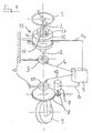
- an electric steering device of a truck in which the rotational movement of a designed as a steering wheel steering member 1 is transmitted via a steering shaft 2 to a steering signal generator 3.
- the mounted on a truck-mounted component 10 steering signal generator 3 is connected via a signal line 4 with an electrical control device 5, which controls a steering motor 6 via an electric steering motor 7.
- the steering motor 7 Via a steering gear 8, the steering motor 7 generates a steering movement of the steerable wheel 9.
- the actual steering position of the steerable wheel 9 is detected by means of a steering angle sensor 11 and also supplied via a signal line 11 to the control device.
- a braking device 13 is arranged on the steering shaft 2, which in this embodiment has a single, controllable by the control device 5 via a control line 14 brake element.
- the brake element comprises a non-rotatably attached to the truck component 10 fixed brake housing 15 and a brake body 16.
- the brake body 16 can be freely rotated relative to the brake housing 15, when the brake element is actuated, the brake body 16 is fixed in the brake housing 15 virtually torsionally rigid ,
- the brake body 16 is connected to the steering shaft 2 via a shaft connection with play.
- the shaft connection comprises a pin 17 which is arranged on the steering shaft 2 and which engages in a recess 18 on the brake body 16. Since the recess 18 is larger in the circumferential direction than the diameter of the pin 17, the shaft connection has play.
- the operation is as follows: When the steering member 1 is rotated starting from the position shown to the left (counterclockwise), the brake body 16 rotates, since the pin 17 abuts against the corresponding side of the recess 18. Now, if the steerable wheel 9 reaches its left stop, not shown, recognizes the control device 5 based on the corresponding output signal of the steering sensor 11 and causes an actuation of the brake element, so that the brake body 16 is fixed and thereby further rotation of the steering member 1 is prevented to the left , A turning back of the steering member 1 and the steering shaft 2 to the right, however, initially unhindered possible because this movement is not initially transmitted to the brake body 16 due to the game in the shaft connection.
- Figure 2 shows an identical with respect to the operation of the steering function arrangement.
- the brake device 13 arranged on the continuous steering shaft 2 has two brake elements each with a brake housing 15a, 15b and in each case a brake body 16a, 16b.
- the brake bodies 16a, 16b are connected by means of a respective freewheel 19a, 19b with the steering shaft 2, the freewheel 19a at any time a rotational movement of the steering shaft 2 and thus the steering member 1 to the right (clockwise) and the freewheel 19b at any time a rotational movement of the steering shaft. 2 to the left (counterclockwise).
- both brake elements are released as long as the steerable wheel 9 does not reach one of its stops.
- Both brake bodies 16a, 16b are freely rotatable in their brake housings 15a, 15b.
- the control device 5 actuates the first brake element, so that the brake body 16a is fixed in the brake housing 15a. Further rotation of the steering member 1 to the left is prevented.
- a turning of the steering member 1 to the right, so a return in the opposite direction, however, is possible by means of the freewheel 19a without noticeable resistance.
- the operation is analog, in which case the second brake body 16b is blocked and the freewheel 19b then allows only a rotation of the steering member 1 to the left.
Landscapes
- Engineering & Computer Science (AREA)
- Transportation (AREA)
- Mechanical Engineering (AREA)
- Structural Engineering (AREA)
- Chemical & Material Sciences (AREA)
- Combustion & Propulsion (AREA)
- Civil Engineering (AREA)
- Life Sciences & Earth Sciences (AREA)
- Geology (AREA)
- Steering Control In Accordance With Driving Conditions (AREA)
- Non-Deflectable Wheels, Steering Of Trailers, Or Other Steering (AREA)
Claims (10)
- Dispositif de direction pour un chariot de manutention, avec un organe de direction rotatif (1), un capteur de signal de direction (3) pour détecter la position angulaire de l'organe de direction (1), et un dispositif de freinage (13) permettant de produire un couple de freinage agissant sur l'organe de direction (1), ainsi qu'une roue directrice (9), un moteur de direction (7) pour produire un mouvement de direction de la roue directrice (9) et un détecteur d'angle de direction (11) pour détecter l'angle de direction de la roue directrice (9), dans lequel le capteur de signal de direction (3), le détecteur d'angle de direction (11), le moteur de direction (7) et le dispositif de freinage (13) sont reliés à un dispositif de commande électrique (5), qui est conçu de telle manière que le dispositif de freinage (13) soit activé lorsque le détecteur d'angle de direction (11) détecte que l'angle de direction de la roue directrice (9) correspond à l'angle de direction maximal, dans lequel le dispositif de freinage (13) est actif pour le sens de rotation de l'organe de direction (1) qui correspond à une augmentation de l'angle de direction, et n'est pas actif pour l'autre sens de rotation de l'organe de direction (1) qui correspond à une diminution de l'angle de direction, et dans lequel le dispositif de freinage (13) comprend au moins un élément de frein, qui comprend un boîtier de frein non rotatif (15, 15a, 15b) et un corps de frein (16, 16a, 16b) pouvant tourner par rapport au boîtier de frein (15, 15a, 15b), dans lequel un mouvement de rotation du corps de frein (16, 16a, 16b) peut être freiné en actionnant l'élément de frein, caractérisé en ce qu'un mouvement de rotation de l'organe de direction (1) peut être transmis au corps de frein (16) au moyen d'une jonction d'arbres, dans lequel la jonction d'arbres présente un jeu défini.
- Dispositif de direction selon la revendication 1, caractérisé en ce que la liaison d'arbres est réalisée de telle manière que, après un changement du sens de rotation de l'organe de direction (1), le mouvement de rotation de l'organe de direction (1) ne soit d'abord pas transmis au corps de frein (16).
- Dispositif de direction selon la revendication 1 ou 2, caractérisé en ce que l'organe de direction (1) comporte un entraîneur (17), qui s'engage dans un évidement sur le corps de frein (16), dans lequel l'évidement (18) est plus grand que l'entraîneur (17) dans la direction périphérique.
- Dispositif de direction pour un chariot de manutention, avec un organe de direction rotatif (1), un capteur de signal de direction (3) pour détecter la position angulaire de l'organe de direction (1), et un dispositif de freinage (13) permettant de produire un couple de freinage agissant sur l'organe de direction (1), ainsi qu'une roue directrice (9), un moteur de direction (7) pour produire un mouvement de direction de la roue directrice (9) et un détecteur d'angle de direction (11) pour détecter l'angle de direction de la roue directrice (9), dans lequel le capteur de signal de direction (3), le détecteur d'angle de direction (11), le moteur de direction (7) et le dispositif de freinage (13) sont reliés à un dispositif de commande électrique (5), qui est conçu de telle manière que le dispositif de freinage (13) soit activé lorsque le détecteur d'angle de direction (11) détecte que l'angle de direction de la roue directrice (9) correspond à l'angle de direction maximal, dans lequel le dispositif de freinage (13) est actif pour le sens de rotation de l'organe de direction (1) qui correspond à une augmentation de l'angle de direction, et n'est pas actif pour l'autre sens de rotation de l'organe de direction (1) qui correspond à une diminution de l'angle de direction, et dans lequel le dispositif de freinage (13) comprend au moins un élément de frein, qui comprend un boîtier de frein non rotatif (15, 15a, 15b) et un corps de frein (16, 16a, 16b) pouvant tourner par rapport au boîtier de frein (15, 15a, 15b), dans lequel un mouvement de rotation du corps de frein (16, 16a, 16b) peut être freiné en actionnant l'élément de frein, caractérisé en ce l'organe de direction (1) est relié à l'au moins un corps de frein (16a) au moyen d'au moins une roue libre (19a), dans lequel la roue libre (19a) transmet un mouvement de l'organe de direction (1) dans un premier sens de rotation au corps de frein (16a) et la roue libre (19a) ne transmet pas un mouvement de l'organe de direction (1) dans un deuxième sens de rotation, opposé au premier sens de rotation, au corps de frein (16a).
- Dispositif de direction selon la revendication 4, caractérisé en ce que le dispositif de freinage (13) comprend un autre élément de frein, dont le corps de frein (16b) est également relié à l'organe de direction (1) au moyen d'une autre roue libre (19b), dans lequel l'autre roue libre (19b) transmet un mouvement de l'organe de direction (1) dans le deuxième sens de rotation au corps de frein (16b) et l'autre roue libre (19b) ne transmet pas un mouvement de l'organe de direction (1) dans le premier sens de rotation au corps de frein (16b).
- Dispositif de direction selon la revendication 5, caractérisé en ce que le dispositif de commande (5) est conçu de telle manière que le premier élément de frein du dispositif de freinage (13) soit activé lorsque le détecteur d'angle de direction (11) détecte que l'angle de direction de la roue directrice (9) correspond à l'angle de direction maximal vers la gauche, et que le deuxième élément de frein du dispositif de freinage (13) soit activé lorsque le détecteur d'angle de direction (11) détecte que l'angle de direction de la roue directrice (9) correspond à l'angle de direction maximal vers la droite.
- Dispositif de direction pour un chariot de manutention, avec un organe de direction rotatif (1), un capteur de signal de direction (3) pour détecter la position angulaire de l'organe de direction (1), et un dispositif de freinage (13) permettant de produire un couple de freinage agissant sur l'organe de direction (1), ainsi qu'une roue directrice (9), un moteur de direction (7) pour produire un mouvement de direction de la roue directrice (9) et un détecteur d'angle de direction (11) pour détecter l'angle de direction de la roue directrice (9), dans lequel le capteur de signal de direction (3), le détecteur d'angle de direction (11), le moteur de direction (7) et le dispositif de freinage (13) sont reliés à un dispositif de commande électrique (5), qui est conçu de telle manière que le dispositif de freinage (13) soit activé lorsque le détecteur d'angle de direction (11) détecte que l'angle de direction de la roue directrice (9) correspond à l'angle de direction maximal, dans lequel le dispositif de freinage (13) est actif pour le sens de rotation de l'organe de direction (1) qui correspond à une augmentation de l'angle de direction, et n'est pas actif pour l'autre sens de rotation de l'organe de direction (1) qui correspond à une diminution de l'angle de direction, caractérisé en ce que le dispositif de freinage (13) comporte au moins une roue libre commutable, qui comprend un boîtier de roue libre non rotatif et un corps de roue libre pouvant tourner par rapport au boîtier de roue libre, dans lequel le corps de roue libre peut tourner dans les deux sens de rotation dans une première position de commutation de la roue libre, et le corps de roue libre peut tourner dans un premier sens de rotation mais ne peut pas tourner dans un deuxième sens de rotation dans une deuxième position de commutation de la roue libre.
- Dispositif de direction selon la revendication 7, caractérisé en ce que le dispositif de freinage (13) comprend une autre roue libre commutable, dans lequel le corps de roue libre peut tourner dans les deux sens de rotation dans une première position de commutation de l'autre roue libre et le corps de roue libre peut tourner dans le deuxième sens de rotation mais ne peut pas tourner dans le premier sens de rotation dans une deuxième position de commutation de l'autre roue libre.
- Dispositif de rotation selon l'une quelconque des revendications 1 à 6, caractérisé en ce que l'au moins un élément de frein est formé par un frein magnétique.
- Dispositif de direction selon l'une quelconque des revendications 1 à 6, caractérisé en ce que l'au moins un élément de frein est formé par un frein à accumulation.
Applications Claiming Priority (2)
| Application Number | Priority Date | Filing Date | Title |
|---|---|---|---|
| DE2003154410 DE10354410A1 (de) | 2003-11-21 | 2003-11-21 | Lenkvorrichtung für ein Flurförderzeug |
| DE10354410 | 2003-11-21 |
Publications (3)
| Publication Number | Publication Date |
|---|---|
| EP1533211A2 EP1533211A2 (fr) | 2005-05-25 |
| EP1533211A3 EP1533211A3 (fr) | 2005-08-17 |
| EP1533211B1 true EP1533211B1 (fr) | 2007-10-17 |
Family
ID=34428839
Family Applications (1)
| Application Number | Title | Priority Date | Filing Date |
|---|---|---|---|
| EP04025710A Expired - Lifetime EP1533211B1 (fr) | 2003-11-21 | 2004-10-29 | Dispositif de direction pour un chariot de manutention |
Country Status (2)
| Country | Link |
|---|---|
| EP (1) | EP1533211B1 (fr) |
| DE (2) | DE10354410A1 (fr) |
Cited By (3)
| Publication number | Priority date | Publication date | Assignee | Title |
|---|---|---|---|---|
| US7849955B2 (en) | 2008-02-05 | 2010-12-14 | Crown Equipment Corporation | Materials handling vehicle having a steer system including a tactile feedback device |
| WO2025125307A1 (fr) * | 2023-12-12 | 2025-06-19 | Rema Lipprandt Gmbh & Co. Kg | Dispositif de direction d'un véhicule |
| US12509337B2 (en) | 2023-04-13 | 2025-12-30 | Crown Equipment Corporation | Steering shaft assembly for a materials handling vehicle |
Families Citing this family (4)
| Publication number | Priority date | Publication date | Assignee | Title |
|---|---|---|---|---|
| JP4725132B2 (ja) * | 2005-03-01 | 2011-07-13 | 日産自動車株式会社 | 操舵制御装置 |
| DE102006039549A1 (de) * | 2006-08-23 | 2008-03-06 | Jungheinrich Aktiengesellschaft | Flurförderzeug mit einer elektrischen Lenkeinrichtung sowie Verfahren zur Steuerung eines Flurförderzeugs mit einer elektrischen Lenkeinrichtung |
| DE102007013172A1 (de) | 2007-03-20 | 2008-09-25 | Gebrüder Frei GbmH & Co. KG | Lenkantriebssystem |
| JP5945783B2 (ja) * | 2012-09-13 | 2016-07-05 | 日本発條株式会社 | 船舶のヘルム装置 |
Family Cites Families (5)
| Publication number | Priority date | Publication date | Assignee | Title |
|---|---|---|---|---|
| DE4122064A1 (de) * | 1990-07-03 | 1992-01-09 | Zahnradfabrik Friedrichshafen | Schaltbare kupplung |
| GB2378165B (en) | 1999-07-14 | 2003-05-07 | Lansing Linde Ltd | Steering device for a vehicle |
| US6761243B2 (en) * | 2001-12-31 | 2004-07-13 | Visteon Global Technologies, Inc. | Steering control with variable damper assistance and method implementing the same |
| DE10249120A1 (de) * | 2002-10-22 | 2004-05-06 | Zf Lenksysteme Gmbh | Zahnstangen-Servolenkung für Fahrzeuge |
| US6926112B2 (en) * | 2003-10-16 | 2005-08-09 | Visteon Global Technologies, Inc. | End of travel system and method for steer by wire systems |
-
2003
- 2003-11-21 DE DE2003154410 patent/DE10354410A1/de not_active Withdrawn
-
2004
- 2004-10-29 EP EP04025710A patent/EP1533211B1/fr not_active Expired - Lifetime
- 2004-10-29 DE DE200450005251 patent/DE502004005251D1/de not_active Expired - Lifetime
Non-Patent Citations (1)
| Title |
|---|
| None * |
Cited By (8)
| Publication number | Priority date | Publication date | Assignee | Title |
|---|---|---|---|---|
| US7849955B2 (en) | 2008-02-05 | 2010-12-14 | Crown Equipment Corporation | Materials handling vehicle having a steer system including a tactile feedback device |
| US7980352B2 (en) | 2008-02-05 | 2011-07-19 | Crown Equipment Corporation | Materials handling vehicle having a steer system including a tactile feedback device |
| US8172033B2 (en) | 2008-02-05 | 2012-05-08 | Crown Equipment Corporation | Materials handling vehicle with a module capable of changing a steerable wheel to control handle position ratio |
| US8412431B2 (en) | 2008-02-05 | 2013-04-02 | Crown Equipment Corporation | Materials handling vehicle having a control apparatus for determining an acceleration value |
| US8718890B2 (en) | 2008-02-05 | 2014-05-06 | Crown Equipment Corporation | Materials handling vehicle having a control apparatus for determining an acceleration value |
| US9421963B2 (en) | 2008-02-05 | 2016-08-23 | Crown Equipment Corporation | Materials handling vehicle having a control apparatus for determining an acceleration value |
| US12509337B2 (en) | 2023-04-13 | 2025-12-30 | Crown Equipment Corporation | Steering shaft assembly for a materials handling vehicle |
| WO2025125307A1 (fr) * | 2023-12-12 | 2025-06-19 | Rema Lipprandt Gmbh & Co. Kg | Dispositif de direction d'un véhicule |
Also Published As
| Publication number | Publication date |
|---|---|
| EP1533211A3 (fr) | 2005-08-17 |
| DE10354410A1 (de) | 2005-06-23 |
| EP1533211A2 (fr) | 2005-05-25 |
| DE502004005251D1 (de) | 2007-11-29 |
Similar Documents
| Publication | Publication Date | Title |
|---|---|---|
| DE112019002990B4 (de) | Steer-by-Wire-Lenkvorrichtung und Fahrzeug | |
| EP1250251B1 (fr) | Embrayage pour un systeme de direction a commande par cable (steer-by-wire) | |
| DE60202074T2 (de) | Lenkeinheit für steer-by-wire-lenkung | |
| EP3424797B1 (fr) | Embrayage pour un vehicule automobile | |
| EP2417001B1 (fr) | Volant de direction pour véhicule automobile à direction à superposition | |
| DE19902556B4 (de) | Lenkgetrieb mit redundantem Antrieb | |
| DE102008023759A1 (de) | Lenkvorrichtung für ein Kraftfahrzeug mit einem Lenkrad, einer Lenkwelle und einem Überlagerungsgetriebe | |
| DE102004027610A1 (de) | Pedaleinheit und Pedalbaugruppe für Kraftfahrzeug | |
| DE212004000037U1 (de) | Spielzeugfahrzeug | |
| EP1583680A1 (fr) | Colonne de direction pour vehicule automobile | |
| DE4011947A1 (de) | Fahrzeug-lenksystem | |
| DE102007012278A1 (de) | Joystick | |
| DE10126928A1 (de) | Stabilisator für ein Kraftfahrzeug | |
| DE102019202294A1 (de) | Lenkbegrenzungsvorrichtung, Steer-by-Wire-Lenksystem und Fahrzeug | |
| EP1533211B1 (fr) | Dispositif de direction pour un chariot de manutention | |
| DE10344479A1 (de) | Elektrisch betätigte Lenkradschlosseinrichtung | |
| DE102006045382A1 (de) | Lenksystem eines Fahrzeugs mit einer Überlagerungsvorrichtung | |
| DE60314927T2 (de) | Vorrichtung mit veränderlichem Übersetzungsverhältnis | |
| DE19911892A1 (de) | Vorrichtung zur Lenkung eines Fahrzeugs | |
| EP1121278B1 (fr) | Dispositif de commande pour l'allumage et le blocage de la direction d'une automobile | |
| DE102005049012B3 (de) | Antriebsrad für Kleinfahrzeug, insbesondere Rollstuhl | |
| DE102012003303B4 (de) | Stellvorrichtung für eine Federungseinrichtung eines Kraftfahrzeugs | |
| DE3612619C2 (fr) | ||
| DE3505325A1 (de) | Einrichtung zum reibungsfreien kuppeln, welche ein wahlweises abkuppeln einer abtriebswelle von einer antriebswelle erlaubt und gleichzeitig wenigstens eine bremsung der abgekuppelten abtriebswelle bewirkt, mit derartigen einrichtungen versehene motor-achsanordnung und mit einer derartigen achsanordnung versehenes einachsiges motorfahrzeug | |
| DE4340203C2 (de) | Elektrisch angetriebene Lenkvorrichtung |
Legal Events
| Date | Code | Title | Description |
|---|---|---|---|
| PUAI | Public reference made under article 153(3) epc to a published international application that has entered the european phase |
Free format text: ORIGINAL CODE: 0009012 |
|
| AK | Designated contracting states |
Kind code of ref document: A2 Designated state(s): AT BE BG CH CY CZ DE DK EE ES FI FR GB GR HU IE IT LI LU MC NL PL PT RO SE SI SK TR |
|
| AX | Request for extension of the european patent |
Extension state: AL HR LT LV MK |
|
| PUAL | Search report despatched |
Free format text: ORIGINAL CODE: 0009013 |
|
| AK | Designated contracting states |
Kind code of ref document: A3 Designated state(s): AT BE BG CH CY CZ DE DK EE ES FI FR GB GR HU IE IT LI LU MC NL PL PT RO SE SI SK TR |
|
| AX | Request for extension of the european patent |
Extension state: AL HR LT LV MK |
|
| 17P | Request for examination filed |
Effective date: 20060124 |
|
| AKX | Designation fees paid |
Designated state(s): DE FR GB IT SE |
|
| 17Q | First examination report despatched |
Effective date: 20060407 |
|
| GRAP | Despatch of communication of intention to grant a patent |
Free format text: ORIGINAL CODE: EPIDOSNIGR1 |
|
| RIC1 | Information provided on ipc code assigned before grant |
Ipc: B62D 6/00 20060101AFI20070612BHEP |
|
| GRAS | Grant fee paid |
Free format text: ORIGINAL CODE: EPIDOSNIGR3 |
|
| GRAA | (expected) grant |
Free format text: ORIGINAL CODE: 0009210 |
|
| AK | Designated contracting states |
Kind code of ref document: B1 Designated state(s): DE FR GB IT SE |
|
| REG | Reference to a national code |
Ref country code: GB Ref legal event code: FG4D Free format text: NOT ENGLISH |
|
| REF | Corresponds to: |
Ref document number: 502004005251 Country of ref document: DE Date of ref document: 20071129 Kind code of ref document: P |
|
| REG | Reference to a national code |
Ref country code: SE Ref legal event code: TRGR |
|
| RAP2 | Party data changed (patent owner data changed or rights of a patent transferred) |
Owner name: STILL WAGNER GMBH |
|
| GBV | Gb: ep patent (uk) treated as always having been void in accordance with gb section 77(7)/1977 [no translation filed] | ||
| EN | Fr: translation not filed | ||
| PLBE | No opposition filed within time limit |
Free format text: ORIGINAL CODE: 0009261 |
|
| STAA | Information on the status of an ep patent application or granted ep patent |
Free format text: STATUS: NO OPPOSITION FILED WITHIN TIME LIMIT |
|
| 26N | No opposition filed |
Effective date: 20080718 |
|
| PG25 | Lapsed in a contracting state [announced via postgrant information from national office to epo] |
Ref country code: FR Free format text: LAPSE BECAUSE OF FAILURE TO SUBMIT A TRANSLATION OF THE DESCRIPTION OR TO PAY THE FEE WITHIN THE PRESCRIBED TIME-LIMIT Effective date: 20080801 |
|
| PG25 | Lapsed in a contracting state [announced via postgrant information from national office to epo] |
Ref country code: GB Free format text: LAPSE BECAUSE OF FAILURE TO SUBMIT A TRANSLATION OF THE DESCRIPTION OR TO PAY THE FEE WITHIN THE PRESCRIBED TIME-LIMIT Effective date: 20071017 |
|
| PG25 | Lapsed in a contracting state [announced via postgrant information from national office to epo] |
Ref country code: FR Free format text: LAPSE BECAUSE OF FAILURE TO SUBMIT A TRANSLATION OF THE DESCRIPTION OR TO PAY THE FEE WITHIN THE PRESCRIBED TIME-LIMIT Effective date: 20071031 |
|
| PGFP | Annual fee paid to national office [announced via postgrant information from national office to epo] |
Ref country code: IT Payment date: 20081025 Year of fee payment: 5 |
|
| PG25 | Lapsed in a contracting state [announced via postgrant information from national office to epo] |
Ref country code: IT Free format text: LAPSE BECAUSE OF NON-PAYMENT OF DUE FEES Effective date: 20091029 |
|
| REG | Reference to a national code |
Ref country code: DE Ref legal event code: R081 Ref document number: 502004005251 Country of ref document: DE Owner name: STILL GMBH, DE Free format text: FORMER OWNER: STILL WAGNER GMBH, 72766 REUTLINGEN, DE Effective date: 20110405 |
|
| REG | Reference to a national code |
Ref country code: DE Ref legal event code: R082 Ref document number: 502004005251 Country of ref document: DE Representative=s name: GEIRHOS & WALLER PATENT- UND RECHTSANWAELTE, DE |
|
| REG | Reference to a national code |
Ref country code: DE Ref legal event code: R082 Ref document number: 502004005251 Country of ref document: DE Representative=s name: PATENTSHIP PATENTANWALTSGESELLSCHAFT MBH, DE Effective date: 20111010 Ref country code: DE Ref legal event code: R081 Ref document number: 502004005251 Country of ref document: DE Owner name: STILL GMBH, DE Free format text: FORMER OWNER: KION WAREHOUSE SYSTEMS GMBH, 72766 REUTLINGEN, DE Effective date: 20111010 Ref country code: DE Ref legal event code: R082 Ref document number: 502004005251 Country of ref document: DE Representative=s name: GEIRHOS & WALLER PATENT- UND RECHTSANWAELTE, DE Effective date: 20111010 |
|
| REG | Reference to a national code |
Ref country code: DE Ref legal event code: R082 Ref document number: 502004005251 Country of ref document: DE Representative=s name: PATENTSHIP PATENTANWALTSGESELLSCHAFT MBH, DE |
|
| REG | Reference to a national code |
Ref country code: DE Ref legal event code: R082 Ref document number: 502004005251 Country of ref document: DE Representative=s name: PATENTSHIP PATENTANWALTSGESELLSCHAFT MBH, DE |
|
| PGFP | Annual fee paid to national office [announced via postgrant information from national office to epo] |
Ref country code: SE Payment date: 20221020 Year of fee payment: 19 Ref country code: DE Payment date: 20221020 Year of fee payment: 19 |
|
| REG | Reference to a national code |
Ref country code: DE Ref legal event code: R119 Ref document number: 502004005251 Country of ref document: DE |
|
| REG | Reference to a national code |
Ref country code: SE Ref legal event code: EUG |
|
| PG25 | Lapsed in a contracting state [announced via postgrant information from national office to epo] |
Ref country code: DE Free format text: LAPSE BECAUSE OF NON-PAYMENT OF DUE FEES Effective date: 20240501 |
|
| PG25 | Lapsed in a contracting state [announced via postgrant information from national office to epo] |
Ref country code: SE Free format text: LAPSE BECAUSE OF NON-PAYMENT OF DUE FEES Effective date: 20231030 |