EP1533190A1 - Vorrichtung und Methode zur Einstellung der Fahrerposition - Google Patents
Vorrichtung und Methode zur Einstellung der Fahrerposition Download PDFInfo
- Publication number
- EP1533190A1 EP1533190A1 EP04027199A EP04027199A EP1533190A1 EP 1533190 A1 EP1533190 A1 EP 1533190A1 EP 04027199 A EP04027199 A EP 04027199A EP 04027199 A EP04027199 A EP 04027199A EP 1533190 A1 EP1533190 A1 EP 1533190A1
- Authority
- EP
- European Patent Office
- Prior art keywords
- adjusting device
- position adjusting
- driver
- pedal
- floor panel
- Prior art date
- Legal status (The legal status is an assumption and is not a legal conclusion. Google has not performed a legal analysis and makes no representation as to the accuracy of the status listed.)
- Granted
Links
Images


Classifications
-
- B—PERFORMING OPERATIONS; TRANSPORTING
- B60—VEHICLES IN GENERAL
- B60R—VEHICLES, VEHICLE FITTINGS, OR VEHICLE PARTS, NOT OTHERWISE PROVIDED FOR
- B60R16/00—Electric or fluid circuits specially adapted for vehicles and not otherwise provided for; Arrangement of elements of electric or fluid circuits specially adapted for vehicles and not otherwise provided for
- B60R16/02—Electric or fluid circuits specially adapted for vehicles and not otherwise provided for; Arrangement of elements of electric or fluid circuits specially adapted for vehicles and not otherwise provided for electric constitutive elements
- B60R16/037—Electric or fluid circuits specially adapted for vehicles and not otherwise provided for; Arrangement of elements of electric or fluid circuits specially adapted for vehicles and not otherwise provided for electric constitutive elements for occupant comfort, e.g. for automatic adjustment of appliances according to personal settings, e.g. seats, mirrors, steering wheel
-
- Y—GENERAL TAGGING OF NEW TECHNOLOGICAL DEVELOPMENTS; GENERAL TAGGING OF CROSS-SECTIONAL TECHNOLOGIES SPANNING OVER SEVERAL SECTIONS OF THE IPC; TECHNICAL SUBJECTS COVERED BY FORMER USPC CROSS-REFERENCE ART COLLECTIONS [XRACs] AND DIGESTS
- Y10—TECHNICAL SUBJECTS COVERED BY FORMER USPC
- Y10T—TECHNICAL SUBJECTS COVERED BY FORMER US CLASSIFICATION
- Y10T74/00—Machine element or mechanism
- Y10T74/20—Control lever and linkage systems
- Y10T74/20576—Elements
- Y10T74/20888—Pedals
Definitions
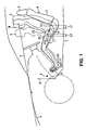
- the drivers L , M and S adjust their driving positions themselves to obtain the proper operation of the accelerator pedal 102 and a brake pedal and the clear front view.
- the height of pedal pressing face can be adjusted respectively by the pedal position adjusting device: in the lower position for the large size of driver with long legs; in the upper position for the small size of driver with short legs; and in the middle position for the standard size of driver.
- the pedal operation can be further improved, enabling the driver to press the pedal center.
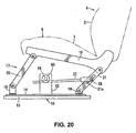
- both the proper driving position and the clear front view can be obtained, and such proper driving position can be obtained even though the longitudinal adjusting distance of the seat is small, and also the proper pedal operation can be obtained by adjusting the floor panel.
- the pedal operating position and angle, floor panel position and seat face position are adjusted, optimization of the leg-portion angle and the pedal operating direction of the driver operating the pedal can be attained. Further, optimization of the arm-portion angle of the driver operating the steering wheel can be attained by the adjustment of steering position.
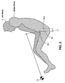
- a reference character L denotes a large size of driver
- a reference character M denotes a standard (medium) size of driver
- a reference character S denotes a small size of driver.
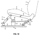
- the drivers L , M and S sit on a seat (driver seat) 4 including a seat cushion 1 , a seat back 2 and a headrest 3 .
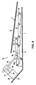
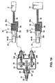
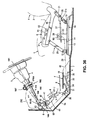
- a gearbox 37 is attached via a bracket 36 to a lower-end slant portion 6a of the dash lower panel 6 , utilizing an open space, a rack member 39 is driven by a pinion 38 or a worm which is supported in the gearbox 37 , a pin 40 at the rear end of the rack member 39 is inserted in a long or oblong hole 34a of the front link 34 , and the link 34 is configured so as to get up or down or recline forward or backward according to the back-and-forth movement of the above-described rack member 39 .
- the seat position adjusting device 17 adjusts the seat-face position of the seat 4 on which the drivers L, M and S
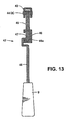
- the pedal position adjusting devices 42 and 42B adjust the operating angles or inclinations of the pedals 9 and 51 operated by the driver's leg portions
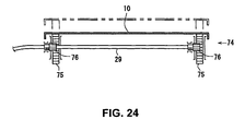
- the movable floor panel adjusting mechanism 30 adjusts the position of the movable floor panel 10 on which the leg portions (specifically, see the heels) of the driver operating the pedals 9 and 51 are placed.
- the movable floor panel adjusting mechanism 30, the seat position adjusting device 17, and the pedal position adjusting devices 42 and 42B are operated preferably together by the driving position operating device (see the lever 23 and the flexible shafts 29 , 29A and 29B ), the improvement of operation can be attained.
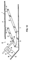
- a plurality of rack members 75 , 75 are fixed to (preferably the bottom face of) the movable floor panel 10 , and pinions 76 , 76 (or worm) meshing with the rack members 75 , 75 are attached to specified (predetermined or predeterminable) portions of the flexible shaft 29 which correspond respectively to the rack members 75 , 75 . Accordingly, the movable floor panel 10 is moved substantially up and down or away and towards the floor panel 7 via the rack and poison mechanism during the rotation of the flexible shaft 29 .
- the pedal position adjusting devices 42 and 42B operative to adjust the operating angles of the pedals 9 and 51 operated by the drivers L , M and S . Accordingly, since the pedal operating angles of the pedals 9 and 51 are adjusted in addition to the adjustment of position of the movable floor panel 10 , the leg of even small size of driver S can reach the pedals enough to provide the proper driving position. This proper driving position can also improve the operation of pedals 9 and 51 and steering wheel 161 and provide the driver with the proper sitting on the seat 4 . Thus, proper views for vehicle side mirrors, providing the narrower view angle, and vehicle meters advantageously are obtained as well.
Applications Claiming Priority (8)
| Application Number | Priority Date | Filing Date | Title |
|---|---|---|---|
| JP2003390121 | 2003-11-20 | ||
| JP2003390121A JP4341381B2 (ja) | 2003-11-20 | 2003-11-20 | 車両の運転姿勢調整装置 |
| JP2003400988A JP4306431B2 (ja) | 2003-12-01 | 2003-12-01 | 車両の運転姿勢調整装置 |
| JP2003400988 | 2003-12-01 | ||
| JP2003405362A JP4259301B2 (ja) | 2003-12-04 | 2003-12-04 | 車両の運転姿勢調整装置 |
| JP2003405362 | 2003-12-04 | ||
| JP2003422415 | 2003-12-19 | ||
| JP2003422415A JP4479233B2 (ja) | 2003-12-19 | 2003-12-19 | 車両の運転姿勢調整装置 |
Publications (2)
| Publication Number | Publication Date |
|---|---|
| EP1533190A1 true EP1533190A1 (de) | 2005-05-25 |
| EP1533190B1 EP1533190B1 (de) | 2006-07-26 |
Family
ID=34437730
Family Applications (1)
| Application Number | Title | Priority Date | Filing Date |
|---|---|---|---|
| EP04027199A Expired - Fee Related EP1533190B1 (de) | 2003-11-20 | 2004-11-16 | Vorrichtung und Methode zur Einstellung der Fahrerposition |
Country Status (3)
| Country | Link |
|---|---|
| US (1) | US7419029B2 (de) |
| EP (1) | EP1533190B1 (de) |
| DE (1) | DE602004001654T2 (de) |
Cited By (4)
| Publication number | Priority date | Publication date | Assignee | Title |
|---|---|---|---|---|
| FR3065410A1 (fr) * | 2017-04-25 | 2018-10-26 | Faurecia Interieur Industrie | Vehicule comprenant un dispositif de support de pieds deformable |
| CN109955741A (zh) * | 2018-10-29 | 2019-07-02 | 永康市臣贸工贸有限公司 | 电动座椅自动调节机构 |
| FR3105948A1 (fr) * | 2020-01-03 | 2021-07-09 | Faurecia Sièges d'Automobile | Support de siège de véhicule, ensemble de siège comportant un tel support et procédé de montage d’un tel dans un véhicule |
| EP3960547A1 (de) * | 2020-08-31 | 2022-03-02 | FERRARI S.p.A. | Verfahren zur automatisierten anpassung eines cockpits innerhalb eines strassenfahrzeugs und zugehöriges strassenfahrzeug |
Families Citing this family (18)
| Publication number | Priority date | Publication date | Assignee | Title |
|---|---|---|---|---|
| DE102004051256A1 (de) * | 2004-10-21 | 2006-05-24 | Deere & Company, Moline | Anpassungsvorrichtung für eine Fahrzeugplattform |
| US20070034435A1 (en) * | 2004-11-24 | 2007-02-15 | Berg Norman O | Adjustable ergonomic vehicles |
| US20070158116A1 (en) * | 2006-01-12 | 2007-07-12 | Trw Automotive U.S. Llc | Adjustable steering column assembly |
| EP1816056B1 (de) * | 2006-02-02 | 2016-11-02 | Mazda Motor Corporation | Vorrichtung für einen beweglichen Boden eines Kraftfahrzeugs |
| JP2007216751A (ja) * | 2006-02-15 | 2007-08-30 | Mazda Motor Corp | 運転姿勢調節装置 |
| US7533936B2 (en) | 2006-08-24 | 2009-05-19 | Mazda Motor Corporation | Vehicle seat assembly |
| US7712816B2 (en) * | 2006-08-25 | 2010-05-11 | Mazda Motor Corporation | Movable floor apparatus for vehicle |
| US7695045B2 (en) | 2007-03-30 | 2010-04-13 | Mazda Motor Corporation | Driving position adjusting device |
| EP2045119A3 (de) * | 2007-10-02 | 2011-02-23 | Mazda Motor Corporation | Fahrhaltungseinstellungsvorrichtung |
| US7946641B2 (en) * | 2008-03-04 | 2011-05-24 | Mazda Motor Corporation | Driver-side floor structure of vehicle |
| IT1393265B1 (it) * | 2009-03-17 | 2012-04-12 | Nilfisk Advance Spa | Macchina per la pulizia di superfici con operatore a bordo |
| JP5803180B2 (ja) * | 2011-03-18 | 2015-11-04 | マツダ株式会社 | ペダル傾斜角度の決定方法 |
| CN104709249B (zh) * | 2015-01-27 | 2017-04-12 | 湖南湖大艾盛汽车技术开发有限公司 | 汽车制动踏板的可调及防侵入结构 |
| DE102015212451A1 (de) * | 2015-07-02 | 2017-01-05 | Bayerische Motoren Werke Aktiengesellschaft | Verfahren und Steuereinheit zur Festlegung einer Sitzposition in einem Fahrzeug |
| JP2018197089A (ja) * | 2017-05-25 | 2018-12-13 | トヨタ紡織株式会社 | 乗物用フットレスト装置 |
| JP2020131923A (ja) * | 2019-02-20 | 2020-08-31 | 本田技研工業株式会社 | 乗員姿勢調整装置およびペダル装置 |
| CN113040571B (zh) * | 2021-04-15 | 2022-05-03 | 吾将文化科技集团有限公司 | 一种基于液压的互动展台 |
| DE102022203637A1 (de) | 2022-04-11 | 2023-10-12 | Volkswagen Aktiengesellschaft | Verfahren zum Einstellen von Fahrmodi eines Fahrzeugs |
Citations (4)
| Publication number | Priority date | Publication date | Assignee | Title |
|---|---|---|---|---|
| JPH0796784A (ja) | 1993-09-29 | 1995-04-11 | Mazda Motor Corp | 車両の運転姿勢調整装置 |
| US5748473A (en) * | 1992-05-05 | 1998-05-05 | Automotive Technologies International, Inc. | Automatic vehicle seat adjuster |
| WO2001064468A1 (de) * | 2000-03-02 | 2001-09-07 | Siemens Aktiengesellschaft | Verfahren und system zum einstellen von für die benutzung eines kraftfahrzeugs relevanten parametern |
| WO2003078201A1 (en) * | 2002-03-14 | 2003-09-25 | Intier Automotive Inc. | Drop down stow in floor automotive vehicle seat assembly |
Family Cites Families (11)
| Publication number | Priority date | Publication date | Assignee | Title |
|---|---|---|---|---|
| US3288239A (en) * | 1964-05-25 | 1966-11-29 | Gen Motors Corp | Adjustable toeboard and control pedal for vehicles |
| DE2510725C2 (de) * | 1975-03-12 | 1985-02-21 | Dr.Ing.H.C. F. Porsche Ag, 7000 Stuttgart | Knierückhaltevorrichtung für Kraftfahrzeuginsassen |
| US4392546A (en) * | 1980-12-24 | 1983-07-12 | Deere & Company | Suspended operator station |
| US4484722A (en) * | 1982-06-30 | 1984-11-27 | The United States Of America As Represented By The Secretary Of The Air Force | Translating rudder pedal system |
| JP2989680B2 (ja) * | 1991-02-15 | 1999-12-13 | 株式会社山田製作所 | チルト・テレスコピックステアリング装置 |
| US6151986A (en) * | 1997-10-09 | 2000-11-28 | Ksr Industrial Corporation | Adjustable vehicle control pedals |
| SE518099C2 (sv) * | 1997-11-21 | 2002-08-27 | Claes Johansson Automotive Ab | Inställbart pedalställ för ett fordon |
| US6293584B1 (en) * | 1998-09-23 | 2001-09-25 | Vehicle Safety Systems, Inc. | Vehicle air bag minimum distance enforcement apparatus, method and system |
| JP4599696B2 (ja) * | 2000-09-21 | 2010-12-15 | アイシン精機株式会社 | 自動車のドライビングポジション調整装置 |
| US6450530B1 (en) * | 2000-10-17 | 2002-09-17 | Ford Global Technologies, Inc. | Seating system with optimum visibilty |
| US6474728B1 (en) * | 2000-10-17 | 2002-11-05 | Ford Global Technologies, Inc. | Adjustable pedalbox and floor for an automobile interior |
-
2004
- 2004-10-20 US US10/968,389 patent/US7419029B2/en not_active Expired - Fee Related
- 2004-11-16 EP EP04027199A patent/EP1533190B1/de not_active Expired - Fee Related
- 2004-11-16 DE DE602004001654T patent/DE602004001654T2/de active Active
Patent Citations (4)
| Publication number | Priority date | Publication date | Assignee | Title |
|---|---|---|---|---|
| US5748473A (en) * | 1992-05-05 | 1998-05-05 | Automotive Technologies International, Inc. | Automatic vehicle seat adjuster |
| JPH0796784A (ja) | 1993-09-29 | 1995-04-11 | Mazda Motor Corp | 車両の運転姿勢調整装置 |
| WO2001064468A1 (de) * | 2000-03-02 | 2001-09-07 | Siemens Aktiengesellschaft | Verfahren und system zum einstellen von für die benutzung eines kraftfahrzeugs relevanten parametern |
| WO2003078201A1 (en) * | 2002-03-14 | 2003-09-25 | Intier Automotive Inc. | Drop down stow in floor automotive vehicle seat assembly |
Cited By (6)
| Publication number | Priority date | Publication date | Assignee | Title |
|---|---|---|---|---|
| FR3065410A1 (fr) * | 2017-04-25 | 2018-10-26 | Faurecia Interieur Industrie | Vehicule comprenant un dispositif de support de pieds deformable |
| US10703246B2 (en) | 2017-04-25 | 2020-07-07 | Faurecia Interieur Industrie | Vehicle comprising a deformable feet support device |
| CN109955741A (zh) * | 2018-10-29 | 2019-07-02 | 永康市臣贸工贸有限公司 | 电动座椅自动调节机构 |
| FR3105948A1 (fr) * | 2020-01-03 | 2021-07-09 | Faurecia Sièges d'Automobile | Support de siège de véhicule, ensemble de siège comportant un tel support et procédé de montage d’un tel dans un véhicule |
| US11590874B2 (en) | 2020-01-03 | 2023-02-28 | Faurecia Sièges d'Automobile | Vehicle seat support, seat assembly comprising such a support, and method for mounting in a vehicle |
| EP3960547A1 (de) * | 2020-08-31 | 2022-03-02 | FERRARI S.p.A. | Verfahren zur automatisierten anpassung eines cockpits innerhalb eines strassenfahrzeugs und zugehöriges strassenfahrzeug |
Also Published As
| Publication number | Publication date |
|---|---|
| US7419029B2 (en) | 2008-09-02 |
| DE602004001654T2 (de) | 2007-07-26 |
| EP1533190B1 (de) | 2006-07-26 |
| US20050109555A1 (en) | 2005-05-26 |
| DE602004001654D1 (de) | 2006-09-07 |
Similar Documents
| Publication | Publication Date | Title |
|---|---|---|
| EP1533190B1 (de) | Vorrichtung und Methode zur Einstellung der Fahrerposition | |
| US7695045B2 (en) | Driving position adjusting device | |
| US7517019B2 (en) | Vehicle driving posture adjusting device | |
| US6857498B2 (en) | Console with driver's interface | |
| JPH11327673A (ja) | 調整可能ペダル装置 | |
| US6030043A (en) | Motor vehicle seat, in particular back seat | |
| JP2009208636A (ja) | 自動車運転席のフロア構造 | |
| US9707864B2 (en) | Seat device of vehicle | |
| US20060169863A1 (en) | Seat position adjusting device of automotive vehicle | |
| JP4479233B2 (ja) | 車両の運転姿勢調整装置 | |
| JP4492383B2 (ja) | 自動車のシート位置調整装置 | |
| JP2004519766A (ja) | 乗物用のフットレスト及びこれを用いた自動車 | |
| EP1571064B1 (de) | Einstellbarer Pedal- und Lenksäulemechanismus | |
| JP4894787B2 (ja) | 自動車運転席のフロア構造 | |
| JP4341381B2 (ja) | 車両の運転姿勢調整装置 | |
| JP3145430B2 (ja) | 自動車のドライビングポジション調整装置 | |
| JP4259301B2 (ja) | 車両の運転姿勢調整装置 | |
| JP3513890B2 (ja) | 車両の運転姿勢調整装置 | |
| CN206664363U (zh) | 用于车辆的扶手组件、车辆中央控制台组件以及车辆 | |
| JP4341389B2 (ja) | 車両の運転姿勢調整装置 | |
| EP1849651A2 (de) | Sitz für Erdbaumaschinen oder Ähnliches | |
| JP4306431B2 (ja) | 車両の運転姿勢調整装置 | |
| JP5277666B2 (ja) | 自動車運転席のフロア構造 | |
| JP3303716B2 (ja) | 車両用シート姿勢制御装置 | |
| JP4894786B2 (ja) | 自動車運転席のフロア構造 |
Legal Events
| Date | Code | Title | Description |
|---|---|---|---|
| PUAI | Public reference made under article 153(3) epc to a published international application that has entered the european phase |
Free format text: ORIGINAL CODE: 0009012 |
|
| AK | Designated contracting states |
Kind code of ref document: A1 Designated state(s): AT BE BG CH CY CZ DE DK EE ES FI FR GB GR HU IE IS IT LI LU MC NL PL PT RO SE SI SK TR |
|
| AX | Request for extension of the european patent |
Extension state: AL HR LT LV MK YU |
|
| 17P | Request for examination filed |
Effective date: 20051006 |
|
| GRAP | Despatch of communication of intention to grant a patent |
Free format text: ORIGINAL CODE: EPIDOSNIGR1 |
|
| AKX | Designation fees paid |
Designated state(s): DE |
|
| GRAS | Grant fee paid |
Free format text: ORIGINAL CODE: EPIDOSNIGR3 |
|
| GRAA | (expected) grant |
Free format text: ORIGINAL CODE: 0009210 |
|
| AK | Designated contracting states |
Kind code of ref document: B1 Designated state(s): DE |
|
| REF | Corresponds to: |
Ref document number: 602004001654 Country of ref document: DE Date of ref document: 20060907 Kind code of ref document: P |
|
| PLBE | No opposition filed within time limit |
Free format text: ORIGINAL CODE: 0009261 |
|
| STAA | Information on the status of an ep patent application or granted ep patent |
Free format text: STATUS: NO OPPOSITION FILED WITHIN TIME LIMIT |
|
| 26N | No opposition filed |
Effective date: 20070427 |
|
| PGFP | Annual fee paid to national office [announced via postgrant information from national office to epo] |
Ref country code: DE Payment date: 20171108 Year of fee payment: 14 |
|
| REG | Reference to a national code |
Ref country code: DE Ref legal event code: R119 Ref document number: 602004001654 Country of ref document: DE |
|
| PG25 | Lapsed in a contracting state [announced via postgrant information from national office to epo] |
Ref country code: DE Free format text: LAPSE BECAUSE OF NON-PAYMENT OF DUE FEES Effective date: 20190601 |