EP1533185A1 - Elément de compensation de déviations de tolérance - Google Patents
Elément de compensation de déviations de tolérance Download PDFInfo
- Publication number
- EP1533185A1 EP1533185A1 EP04021661A EP04021661A EP1533185A1 EP 1533185 A1 EP1533185 A1 EP 1533185A1 EP 04021661 A EP04021661 A EP 04021661A EP 04021661 A EP04021661 A EP 04021661A EP 1533185 A1 EP1533185 A1 EP 1533185A1
- Authority
- EP
- European Patent Office
- Prior art keywords
- roof
- counter
- support part
- distance device
- support member
- Prior art date
- Legal status (The legal status is an assumption and is not a legal conclusion. Google has not performed a legal analysis and makes no representation as to the accuracy of the status listed.)
- Granted
Links
Images


Classifications
-
- B—PERFORMING OPERATIONS; TRANSPORTING
- B60—VEHICLES IN GENERAL
- B60R—VEHICLES, VEHICLE FITTINGS, OR VEHICLE PARTS, NOT OTHERWISE PROVIDED FOR
- B60R9/00—Supplementary fittings on vehicle exterior for carrying loads, e.g. luggage, sports gear or the like
- B60R9/04—Carriers associated with vehicle roof
Definitions
- the invention relates to a spacer device for bridging a Freiraums between a support member and a roof body for the attachment of a roof rack, a roof rail, a Roof strip or the like on a vehicle roof.
- the supporting part can absorb the forces that occur which are present in heavy roof loads and especially in accident situations (strong delays) are expected.
- the supporting part is Not visible from the outside, as it is below the sheet of the roof body lies. Also from the interior of the vehicle is the supporting part not visible because of the interior lining (roof paneling) is covered. Between the bottom of the roof body and the top of the support part is a free space formed due to of manufacturing tolerances is more or less high. In the Installation of the roof rack must be ensured that a firm connection to the supporting part exists, but at the same time no Pressure is exerted on the roof body, leading to sheet metal deformation lead and would be recognized as disturbing distortions.
- the spacer device a support member and a counter-support member, said support member and Support member held together via a screw connection and adjustable relative to each other for adjusting the bridging length are, wherein the support member and / or the counter-support part a internal adjustment tool attack seat for a setting Having the bridging length serving adjusting tool.
- the invention further relates to a vehicle roof area with a Carrying part, a distance therefrom and thus a free space to the supporting part forming roof body and one, the bridging the clearance serving distance device for the Fixing a roof rack, a roof rail, a roof rail or the like on the vehicle roof, wherein the supporting part having a tapered in width breakthrough whose maximum width allows the passage of the spacer device and whose tapered width prevents the passage. This allows the Distance device from the vehicle interior ago by the corresponding wide area of the opening inserted in the free space become.
- the spacer device is laterally in Free space shifted, so compared to the aforementioned insertion movement moved transversely thereto, in such a way that the spacer device in the width-tapered region of the aperture so they settle on the edge areas of the breakthrough can support, as this tapered width the passage back in denied the vehicle interior.
- an adjustment tool is used the at the mentioned adjusting tool attack seat of support member and / or counter-support part attacks. At the adjustment tool, the spacer device held axially. The adjusting tool allows the Handling / manipulation of the spacer device, d.
- Adjustment tool allows the distance device from the vehicle interior Insert axially into the free space and displace it radially.
- the terms "axial” and “radial” are on the axis of rotation of the threaded connection related between the support member and the counter support member.
- the spacer device latching and has rotational transmission means on to the relative rotation between the support part and To enable counter-support part.
- the invention further relates to a method for positioning and / or actuation of a spacer device which is in a free space between a supporting part and a roof body for on the Vehicle roof attachment of a roof rack, a roof rail, a roof rail or the like is introduced, wherein the introduction by a breakthrough of the supporting part of Interior of the vehicle is done here.
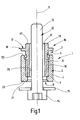
- FIG. 1 shows a spacer device 1, the assembly of a Roof strip on a vehicle roof is used.
- the passage 8 and a corresponding proportion of the through hole 6 of a Shank 13 of a threaded screw 12 passes through.
- the head 14 of the Threaded screw 12 is a relatively large diameter washer 15 assigned.
- the counter-support part 3 protrudes a piece far out of the support part 2 out. This is true even if both parts are bolted together as far as possible and results from the fact that the counter-support part 3 in the region of the outstanding End 16 a roof body contact surface 17 in the form a collar 18 which projects beyond the external thread 10 radially and about a diameter equal to the outer diameter the outer sleeve 4 corresponds.
- the collar 18 is from a Hollow pipe 19 projecting axially, which is integrally formed on the counter support part. 4 formed and is penetrated by the passageway 8.
- the Outer sleeve 4 has its facing the screw head 14, So the collar 18 side facing away from an end face 20, the forms a support member contact surface 21.
- Adjustment tool attack seat 22, 23 is formed, wherein the adjusting tool attack seat 22 on the support member 2 and the adjusting tool-attacking seat 23 is located on the counter support part 3.
- the figure 3 is too see that the adjusting tool attack seat 22 as the end face 20 of the support member 2 open-edge sleeve wall recess 24th is trained. This sleeve wall recess 24 can radially the enforce the entire wall thickness of the outer sleeve 4.
- the adjustment tool has a relative for holding mandrel rotatable stop on, from the end face 20th her axially inserted into at least one of the sleeve wall recesses 24 becomes.
- the arrangement is made such that the Adjusting tool -at least in the spacer device 1 facing Area around the center line 11 lying around the periphery of Distance device 1 is not projected radially to the assembly of the spacer device 1 to make. This will be explained below discussed in more detail. It is possible that the engagement of the retaining pin of the adjusting frictionally in the passageway. 8 he follows.
- the passage 8 may be formed as a cylinder bore.
- the retaining mandrel -in cross section Seen not rotationally symmetrical, but for example as Polygon is formed, with the cross section of the passageway 8 has a corresponding shape, so that a rotational drive can be done.
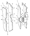
- FIG. 2 shows a vehicle roof area 27 of a not closer shown vehicle.
- the vehicle roof area 27 has a Support member 28 in the form of a stable sheet 29 on and -in the Z direction spaced from it - a roof body 30, so that on the vehicle visible from the outside, painted roof panel 31.
- the present in the Z direction Distance between these two sheets may be in the course of Manufacturing fluctuate due to manufacturing tolerances.
- the supporting part 28 is not visible from the interior of the vehicle as it is covered by the roof lining (sky).
- the roof body 30 is penetrated by a circular opening 32. Below This opening 32 is located in the support member 28 is a tapered Breakthrough 33, which is formed as a keyhole opening 34 is.
- the arrangement is such that the tapered width 35 seen in the Z direction below the opening 32 and that the larger, maximum width 36 of the opening 33 in the X direction offset by the center of the circular opening 32 extending Z-axis is located.
- the Z-axis is in the figure 2 with the line 37 and the center of the maximum width 36 of the Breakthrough 33 indicated by the line 38.
- a free space 39 is formed, which -as below be explained in more detail-bridged by the spacer device 1 becomes.
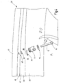
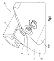
- FIG. 4 illustrates the mounting of a roof rail 41 on the roof Roof 42 of a motor vehicle, not shown.
- the roof 42 is from the resulting from the figures 2 and 3 roof body 30 formed. Seen from the vehicle interior 43 from below the roof body 30, the already mentioned support member 28, being to this support member 28 due to the not yet assembled Roof covering access exists.
- FIG. 4 shows only one Part of the vehicle roof area 27, so only one Section of roof rail 41 to be mounted on the roof.
- the threaded shank 13 of the threaded screw 12 is in a threaded bore 46 'of the roof rail 41st screwed and therefore takes an axial tension of the components before, between the head 14 of the threaded screw 12 and the bottom 46 of the roof rail 41 is a firm tension, without the roof body 30, so the relatively sensitive, painted Roof plate 31 of the motor vehicle are charged excessively would.
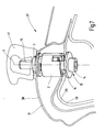
- FIGS. 5 to 8 show sectional views through the vehicle roof area 27. Ferner an adjusting tool 47 can be seen, the one-end an operating portion 48 and at the other end with a retaining pin 49th is provided, as seen from the figure 5, the spacer device 1 can take up by their passageway 8 on the retaining pin 49 axially (center line 11) is plugged. hereby is a positive connection between the retaining pin 49 and passage 8 and therefore the counter support part 3 is generated such that a rotation the operating portion 48 about the center line 11 to a corresponding one Rotation of the counter-support part 3 about the center line 11 leads.
- Relative to the retaining pin 49 is a stop on the adjusting tool 47 50 formed, which is independent of the rotation of the retaining pin 49th or the actuating portion 48 about the center line 11th can be turned.
- the stopper 50 has a parallel to the Holding mandrel 49 extending driving mandrel 51, whose free End portion 52 in one of the sleeve wall recesses 24 of the support member 2 is axially inserted, as can be seen from Figure 5. Of the Driving mandrel 51 extends beyond the periphery of the support member 2 in the radial Not direction.
- the assembly of the spacer device 1 is carried out as follows: a in the interior 43 of the vehicle mechanic is infected the adjusting tool 43 on a spacer device 1, the complete screwed together, that is the underside of the collar 18 rests on the end face 53 of the outer sleeve 4 or has only small Distance from this. He then detects the operating section 48 of the adjusting tool 47 and puts the spacer device 1 from the interior 43 of the vehicle forth in the keyhole opening 34, where the maximum width 36 is present. In this situation, the distance device 1 is in Cavity 39; the operating section 48 lies in the interior space 43, So below the bottom 44 of the support member 28.
- the fitter pulls the adjusting tool 47 axially from the Distance device 1 in the direction of the vehicle interior 43 out.
- the Distance device 1 is pre-assembled so that below the Threaded screw 12 together with washer 15 are mounted can to attach the mentioned roof rail 41.
- Figure 5 shows the means of adjustment 47 in the Freiraum 39 introduced spacer device, wherein the latter still in the bolted state.
- Figure 6 illustrates the axial unscrewing of the support member 2 and counter-support part 3 by means of the adjusting tool 47.
- FIG. 7 shows then the finished assembled state of the roof rail 41.
- the figure 8 corresponds to the illustration of Figure 7, but is as a perspective Drawing executed and therefore illustrates the situation.
- the unscrewing of the support member 2 and the counter-support part 3 takes place in that on the operating portion 48 is an assembly tool, for example a cordless screwdriver, is placed, the one adjustable accordingly Slip clutch, so always a defined torque is exercised and therefore the assembly of the spacer device 1 reproducible occurs.
- the assembly tool a Ratchet that does not allow this counter-rotation.
Landscapes
- Engineering & Computer Science (AREA)
- Mechanical Engineering (AREA)
- Fittings On The Vehicle Exterior For Carrying Loads, And Devices For Holding Or Mounting Articles (AREA)
Priority Applications (2)
| Application Number | Priority Date | Filing Date | Title |
|---|---|---|---|
| SI200432231T SI1533185T1 (sl) | 2003-11-19 | 2004-09-11 | Izravnalni element za toleranäśna odstopanja |
| PL04021661T PL1533185T3 (pl) | 2003-11-19 | 2004-09-11 | Element kompensujący tolerancję wymiaru |
Applications Claiming Priority (2)
| Application Number | Priority Date | Filing Date | Title |
|---|---|---|---|
| DE10354117A DE10354117B4 (de) | 2003-11-19 | 2003-11-19 | Toleranzausgleichselement |
| DE10354117 | 2003-11-19 |
Publications (2)
| Publication Number | Publication Date |
|---|---|
| EP1533185A1 true EP1533185A1 (fr) | 2005-05-25 |
| EP1533185B1 EP1533185B1 (fr) | 2014-12-31 |
Family
ID=34428806
Family Applications (1)
| Application Number | Title | Priority Date | Filing Date |
|---|---|---|---|
| EP04021661.6A Not-in-force EP1533185B1 (fr) | 2003-11-19 | 2004-09-11 | Elément de compensation de déviations de tolérance |
Country Status (8)
| Country | Link |
|---|---|
| US (1) | US7591403B2 (fr) |
| EP (1) | EP1533185B1 (fr) |
| CN (1) | CN1618679B (fr) |
| DE (1) | DE10354117B4 (fr) |
| ES (1) | ES2532093T3 (fr) |
| PL (1) | PL1533185T3 (fr) |
| PT (1) | PT1533185E (fr) |
| SI (1) | SI1533185T1 (fr) |
Cited By (9)
| Publication number | Priority date | Publication date | Assignee | Title |
|---|---|---|---|---|
| FR2920015A3 (fr) * | 2007-08-16 | 2009-02-20 | Renault Sas | Structure de vehicule automobile et procede de fixation d'un accessoire |
| EP2113421A1 (fr) * | 2008-04-30 | 2009-11-04 | Seat, S.A. | Ancrage pour galerie de toit de véhicule |
| EP2532555A3 (fr) * | 2010-10-08 | 2013-01-23 | Skoda Auto a.s. | Dispositif de fixation pour une galerie de toit |
| US8944736B2 (en) * | 2011-10-27 | 2015-02-03 | Böllhoff Verbindungstechnik GmbH | Fastening element with a tolerance-compensation function |
| FR3027570A1 (fr) * | 2014-10-23 | 2016-04-29 | Peugeot Citroen Automobiles Sa | Dispositif de fixation d'une barre de toit sur une caisse de vehicule automobile |
| FR3066732A1 (fr) * | 2017-05-29 | 2018-11-30 | Peugeot Citroen Automobiles Sa | Vehicule avec entretoise de fixation de piece |
| ES2705741A1 (es) * | 2017-09-22 | 2019-03-26 | Itw Metal Fasteners S L | Dispositivo y procedimiento de sujeción de un accesorio de un vehículo |
| ES2737682A1 (es) * | 2018-07-11 | 2020-01-15 | Illinois Tool Works | Tuerca de compensación |
| EP4095395A1 (fr) | 2021-05-27 | 2022-11-30 | Böllhoff Verbindungstechnik GmbH | Élément de réglage, premier composant comprenant l'élément de réglage, structure de connexion comportant le premier composant, procédé de fabrication de l'élément de réglage et procédé de connexion |
Families Citing this family (13)
| Publication number | Priority date | Publication date | Assignee | Title |
|---|---|---|---|---|
| DE102005018158A1 (de) * | 2004-09-24 | 2006-04-06 | Hans und Ottmar Binder GmbH Oberflächenveredelung | Dachträgersystem für ein Fahrzeug sowie Verfahren zur Herstellung des Dachträgersystems und Fahrzeug mit einem Dachträgersystem |
| DE102008026414B4 (de) | 2008-06-02 | 2010-04-08 | Böllhoff Verbindungstechnik GmbH | Toleranzausgleichselement |
| DE102008062894B4 (de) | 2008-12-12 | 2011-07-21 | Hans und Ottmar Binder GbR (vertretungsberechtigte Gesellschafter: Hans Binder, 89558 Böhmenkirch; Ottmar Binder, 89558 Böhmenkirch), 89558 | Distanzvorrichtung und Befestigungsanordnung mit Distanzvorrichtung |
| CN103287345B (zh) * | 2012-02-22 | 2016-12-14 | 标致·雪铁龙汽车公司 | 一种用于机动车的纵向布置的车顶行李架的通用固定设备 |
| US9133870B2 (en) | 2013-04-03 | 2015-09-15 | Ford Global Technologies, Llc | Adjustable tower stud assembly |
| US9302716B2 (en) | 2014-04-14 | 2016-04-05 | Ford Global Technologies, Llc | Compensator assembly for a vehicle frame |
| US9359012B2 (en) | 2014-04-14 | 2016-06-07 | Ford Global Technologies, Llc | Tolerance compensator for a vehicle frame |
| DE102015013598B4 (de) | 2015-10-21 | 2021-04-08 | Audi Ag | Toleranzausgleichselement und zugehörige Kraftfahrzeugkarosserie |
| DE102015122744A1 (de) | 2015-12-23 | 2017-06-29 | Böllhoff Verbindungstechnik GmbH | Verstellbare Distanzhülse |
| CN105564329A (zh) * | 2016-02-04 | 2016-05-11 | 成都银利汽车零部件有限公司 | 支撑调节装置 |
| CN108327644B (zh) * | 2017-01-19 | 2023-03-14 | 福特环球技术公司 | 车顶行李架及包含其的车辆 |
| CN107599993A (zh) * | 2017-09-16 | 2018-01-19 | 湖北博士隆科技股份有限公司 | 外装式公差吸收器 |
| JP6774999B2 (ja) * | 2018-12-12 | 2020-10-28 | 本田技研工業株式会社 | 物品固定装置 |
Citations (10)
| Publication number | Priority date | Publication date | Assignee | Title |
|---|---|---|---|---|
| DE3121086A1 (de) * | 1981-05-27 | 1982-12-16 | Gebr. Happich Gmbh, 5600 Wuppertal | Vorrichtung zur befestigung eines aufbaus, insbesondere einer reling fuer einen dachgepaeckstaender auf einem fahrzeugdach |
| DE3133932A1 (de) * | 1981-08-27 | 1983-03-17 | Volkswagenwerk Ag, 3180 Wolfsburg | "anordnung zur befestigung eines aufbaus, insbesondere einer reling fuer einen dachgepaecktraeger, auf einem fahrzeugdach" |
| DE3524558A1 (de) * | 1985-07-10 | 1987-01-15 | Happich Gmbh Gebr | Vorrichtung zum befestigen eines mit stuetzfuessen versehenen aufbaus, insbesondere einer reling fuer einen dachgepaeckstaender auf einem fahrzeugdach |
| DE3736028C1 (en) * | 1987-10-24 | 1989-02-02 | Bayerische Motoren Werke Ag | Fastening device for a roofrack arranged on a vehicle roof |
| DE3932193A1 (de) * | 1989-09-27 | 1991-04-04 | Bayerische Motoren Werke Ag | Befestigungseinrichtung fuer einen auf einem fahrzeugdach angeordneten gepaecktraeger |
| DE9209769U1 (fr) * | 1992-06-25 | 1992-10-08 | Itw Befestigungssysteme Gmbh, 5860 Iserlohn, De | |
| DE4240079A1 (de) * | 1992-11-28 | 1994-06-01 | Happich Gmbh Gebr | Befestigungsanordnung |
| DE19706611C1 (de) * | 1997-02-20 | 1998-04-09 | Happich Fahrzeug Dachsysteme | Befestigungsvorrichtung |
| WO2003062016A1 (fr) * | 2002-01-25 | 2003-07-31 | Thule Automotive Limited | Moyen de fixation d'une galerie sur le toit d'un vehicule |
| DE10239022A1 (de) * | 2002-08-22 | 2004-03-04 | Sportrack Gmbh | Vorrichtung zur Befestigung einer Dachreling auf einem Fahrzeugdach |
Family Cites Families (16)
| Publication number | Priority date | Publication date | Assignee | Title |
|---|---|---|---|---|
| US1051144A (en) * | 1911-07-12 | 1913-01-21 | Henry C Manny | Lifting-jack. |
| ZA772680B (en) * | 1977-05-04 | 1978-10-25 | Knipping Ltd | An attachment for a power tool |
| US4448336A (en) * | 1979-05-15 | 1984-05-15 | Bott John Anthony | Combination of permanent luggage carrier adapters with selected and removable primary luggage carriers |
| US4299346A (en) * | 1979-10-04 | 1981-11-10 | Auto Trends, Inc. | Automobile luggage rack |
| DE3620005C1 (en) * | 1986-06-13 | 1987-09-03 | Audi Ag | Device for adjusting a first structural part relative to a second structural part |
| US4780571A (en) * | 1986-07-25 | 1988-10-25 | Huang Chien Teh | Combined floor pedestal and floor outlet |
| DE4220842A1 (de) * | 1992-06-25 | 1994-01-05 | Itw Befestigungssysteme | Vorrichtung zum Befestigen eines Bauteils an einem zwei beabstandete Bleche aufweisenden Tragteil |
| DE19542489A1 (de) * | 1995-11-15 | 1997-05-22 | Dethleffs Gmbh | Vorrichtung zur Halterung eines Reserverads |
| DE19546703C1 (de) * | 1995-12-14 | 1997-09-04 | Porsche Ag | Befestigungselement für plattenförmige Bauelemente |
| US6178716B1 (en) * | 1996-01-30 | 2001-01-30 | Chen Hsin-Hsiung | Reinforced-concrete floor slab thickness indicator/reinforcement rod spacer combination |
| US5699944A (en) * | 1996-07-25 | 1997-12-23 | Avibank Mfg., Inc. | Vehicle roof rack assembly |
| KR100391537B1 (ko) * | 1999-12-13 | 2003-07-12 | 기아자동차주식회사 | 자동차의 센터 필라 조립체 |
| TW447424U (en) * | 2000-05-16 | 2001-07-21 | Formosa Saint Jose Corp | Retaining device for sled capable of adjusting position |
| US20040035064A1 (en) * | 2000-05-19 | 2004-02-26 | Kugler William E. | Non-threaded apparatus for selectively adjusting the elevation of a building surface |
| US6363685B1 (en) * | 2000-05-19 | 2002-04-02 | William E. Kugler | Method and apparatus for selectively adjusting the elevation of an undulating or plannar surface |
| GB0100372D0 (en) * | 2001-01-06 | 2001-02-14 | Owen George | Support apparatus |
-
2003
- 2003-11-19 DE DE10354117A patent/DE10354117B4/de not_active Expired - Fee Related
-
2004
- 2004-09-11 PT PT04021661T patent/PT1533185E/pt unknown
- 2004-09-11 ES ES04021661.6T patent/ES2532093T3/es active Active
- 2004-09-11 EP EP04021661.6A patent/EP1533185B1/fr not_active Not-in-force
- 2004-09-11 SI SI200432231T patent/SI1533185T1/sl unknown
- 2004-09-11 PL PL04021661T patent/PL1533185T3/pl unknown
- 2004-11-17 US US10/991,292 patent/US7591403B2/en not_active Expired - Fee Related
- 2004-11-19 CN CN2004100957601A patent/CN1618679B/zh not_active Expired - Fee Related
Patent Citations (10)
| Publication number | Priority date | Publication date | Assignee | Title |
|---|---|---|---|---|
| DE3121086A1 (de) * | 1981-05-27 | 1982-12-16 | Gebr. Happich Gmbh, 5600 Wuppertal | Vorrichtung zur befestigung eines aufbaus, insbesondere einer reling fuer einen dachgepaeckstaender auf einem fahrzeugdach |
| DE3133932A1 (de) * | 1981-08-27 | 1983-03-17 | Volkswagenwerk Ag, 3180 Wolfsburg | "anordnung zur befestigung eines aufbaus, insbesondere einer reling fuer einen dachgepaecktraeger, auf einem fahrzeugdach" |
| DE3524558A1 (de) * | 1985-07-10 | 1987-01-15 | Happich Gmbh Gebr | Vorrichtung zum befestigen eines mit stuetzfuessen versehenen aufbaus, insbesondere einer reling fuer einen dachgepaeckstaender auf einem fahrzeugdach |
| DE3736028C1 (en) * | 1987-10-24 | 1989-02-02 | Bayerische Motoren Werke Ag | Fastening device for a roofrack arranged on a vehicle roof |
| DE3932193A1 (de) * | 1989-09-27 | 1991-04-04 | Bayerische Motoren Werke Ag | Befestigungseinrichtung fuer einen auf einem fahrzeugdach angeordneten gepaecktraeger |
| DE9209769U1 (fr) * | 1992-06-25 | 1992-10-08 | Itw Befestigungssysteme Gmbh, 5860 Iserlohn, De | |
| DE4240079A1 (de) * | 1992-11-28 | 1994-06-01 | Happich Gmbh Gebr | Befestigungsanordnung |
| DE19706611C1 (de) * | 1997-02-20 | 1998-04-09 | Happich Fahrzeug Dachsysteme | Befestigungsvorrichtung |
| WO2003062016A1 (fr) * | 2002-01-25 | 2003-07-31 | Thule Automotive Limited | Moyen de fixation d'une galerie sur le toit d'un vehicule |
| DE10239022A1 (de) * | 2002-08-22 | 2004-03-04 | Sportrack Gmbh | Vorrichtung zur Befestigung einer Dachreling auf einem Fahrzeugdach |
Cited By (11)
| Publication number | Priority date | Publication date | Assignee | Title |
|---|---|---|---|---|
| FR2920015A3 (fr) * | 2007-08-16 | 2009-02-20 | Renault Sas | Structure de vehicule automobile et procede de fixation d'un accessoire |
| EP2113421A1 (fr) * | 2008-04-30 | 2009-11-04 | Seat, S.A. | Ancrage pour galerie de toit de véhicule |
| EP2532555A3 (fr) * | 2010-10-08 | 2013-01-23 | Skoda Auto a.s. | Dispositif de fixation pour une galerie de toit |
| US8944736B2 (en) * | 2011-10-27 | 2015-02-03 | Böllhoff Verbindungstechnik GmbH | Fastening element with a tolerance-compensation function |
| FR3027570A1 (fr) * | 2014-10-23 | 2016-04-29 | Peugeot Citroen Automobiles Sa | Dispositif de fixation d'une barre de toit sur une caisse de vehicule automobile |
| FR3066732A1 (fr) * | 2017-05-29 | 2018-11-30 | Peugeot Citroen Automobiles Sa | Vehicule avec entretoise de fixation de piece |
| ES2705741A1 (es) * | 2017-09-22 | 2019-03-26 | Itw Metal Fasteners S L | Dispositivo y procedimiento de sujeción de un accesorio de un vehículo |
| US10926810B2 (en) | 2017-09-22 | 2021-02-23 | Itw Metal Fasteners, S.L. | Device and method for fastening a vehicle accessory |
| ES2737682A1 (es) * | 2018-07-11 | 2020-01-15 | Illinois Tool Works | Tuerca de compensación |
| EP4095395A1 (fr) | 2021-05-27 | 2022-11-30 | Böllhoff Verbindungstechnik GmbH | Élément de réglage, premier composant comprenant l'élément de réglage, structure de connexion comportant le premier composant, procédé de fabrication de l'élément de réglage et procédé de connexion |
| WO2022248121A1 (fr) | 2021-05-27 | 2022-12-01 | Böllhoff Verbindungstechnik GmbH | Élément de réglage, premier composant doté d'un élément de réglage, structure de liaison comprenant le premier élément, procédé de fabrication de l'élément de réglage et procédé de liaison |
Also Published As
| Publication number | Publication date |
|---|---|
| CN1618679B (zh) | 2010-12-08 |
| ES2532093T3 (es) | 2015-03-24 |
| US7591403B2 (en) | 2009-09-22 |
| CN1618679A (zh) | 2005-05-25 |
| DE10354117A1 (de) | 2005-06-30 |
| PT1533185E (pt) | 2015-03-31 |
| DE10354117B4 (de) | 2007-08-23 |
| SI1533185T1 (sl) | 2015-05-29 |
| US20050102938A1 (en) | 2005-05-19 |
| EP1533185B1 (fr) | 2014-12-31 |
| PL1533185T3 (pl) | 2015-06-30 |
Similar Documents
| Publication | Publication Date | Title |
|---|---|---|
| EP1533185A1 (fr) | Elément de compensation de déviations de tolérance | |
| EP2110565B1 (fr) | Composant de raccordement destiné à la fixation d'un élément de construction sur un élément de support | |
| EP2720907B1 (fr) | Dispositif de fixation comprenant un compensateur de tolérance | |
| DE602005000797T2 (de) | Element zum Befestigen von Zubehörteilen an Metallfenstern und Metalltüren | |
| EP1869334B1 (fr) | Palier lisse, systeme de palier lisse et montage d'un systeme de palier lisse | |
| DE60101761T2 (de) | Gegenlagerböckchen für Fahrzeugsonnenblenden | |
| DE10055647B4 (de) | Hilfsgriffsbefestigungsstruktur und -verfahren | |
| DE112008004188B4 (de) | Befestigungsstruktur mit einer Durchgangstülle | |
| DE102012009173B4 (de) | Toleranzausgleichseinrichtung | |
| DE69917827T2 (de) | Befestigungsvorrichtung | |
| DE102010002847A1 (de) | Blindniet mit einem Nietkörper aus Kunststoff | |
| EP1852643A2 (fr) | Collier destiné à la fixation d'un objet tubulaire | |
| EP3036443B1 (fr) | Procédé pour assembler des pièces et module correspondant | |
| EP3586018B1 (fr) | Dispositif de fixation et module de fixation | |
| WO2006103265A1 (fr) | Element de fixation a monter sur un boulon filete | |
| EP1070003B1 (fr) | Dispositif de fixation de revetements interieurs destine a des vehicules | |
| EP3404153B1 (fr) | Ensemble de fixation destiné à la fixation d'un chassis de montage pour objets sanitaires et utilisation d'un tel ensemble de fixation | |
| EP3569880A1 (fr) | Agencement flottant imperdable d'un élément de raccordement sur un composant | |
| DE102005051172B4 (de) | Befestigungselement für die mechanische Befestigung von Dämm- und Dichtungsmaterialien auf Flachdächern | |
| EP3363969B1 (fr) | Poignée d'actionnement | |
| DE19750252A1 (de) | Befestigungsvorrichtung | |
| DE3114283A1 (de) | "befestigungselement aus kunststoff, insbesondere zur loesbaren befestigung von flachen werkstuecken" | |
| DE102017011237A1 (de) | Befestigungsteil und Dachanordnung | |
| DE102019117086A1 (de) | Befestigungseinheit | |
| DE20317894U1 (de) | Toleranzausgleichselement |
Legal Events
| Date | Code | Title | Description |
|---|---|---|---|
| PUAI | Public reference made under article 153(3) epc to a published international application that has entered the european phase |
Free format text: ORIGINAL CODE: 0009012 |
|
| AK | Designated contracting states |
Kind code of ref document: A1 Designated state(s): AT BE BG CH CY CZ DE DK EE ES FI FR GB GR HU IE IT LI LU MC NL PL PT RO SE SI SK TR |
|
| AX | Request for extension of the european patent |
Extension state: AL HR LT LV MK |
|
| 17P | Request for examination filed |
Effective date: 20051125 |
|
| AKX | Designation fees paid |
Designated state(s): AT BE BG CH CY CZ DE DK EE ES FI FR GB GR HU IE IT LI LU MC NL PL PT RO SE SI SK TR |
|
| 17Q | First examination report despatched |
Effective date: 20131024 |
|
| GRAP | Despatch of communication of intention to grant a patent |
Free format text: ORIGINAL CODE: EPIDOSNIGR1 |
|
| INTG | Intention to grant announced |
Effective date: 20140729 |
|
| GRAS | Grant fee paid |
Free format text: ORIGINAL CODE: EPIDOSNIGR3 |
|
| GRAA | (expected) grant |
Free format text: ORIGINAL CODE: 0009210 |
|
| AK | Designated contracting states |
Kind code of ref document: B1 Designated state(s): AT BE BG CH CY CZ DE DK EE ES FI FR GB GR HU IE IT LI LU MC NL PL PT RO SE SI SK TR |
|
| REG | Reference to a national code |
Ref country code: CH Ref legal event code: EP Ref country code: GB Ref legal event code: FG4D Free format text: NOT ENGLISH |
|
| REG | Reference to a national code |
Ref country code: IE Ref legal event code: FG4D Free format text: LANGUAGE OF EP DOCUMENT: GERMAN |
|
| REG | Reference to a national code |
Ref country code: AT Ref legal event code: REF Ref document number: 704161 Country of ref document: AT Kind code of ref document: T Effective date: 20150215 |
|
| REG | Reference to a national code |
Ref country code: DE Ref legal event code: R096 Ref document number: 502004014801 Country of ref document: DE Effective date: 20150219 |
|
| REG | Reference to a national code |
Ref country code: RO Ref legal event code: EPE |
|
| REG | Reference to a national code |
Ref country code: ES Ref legal event code: FG2A Ref document number: 2532093 Country of ref document: ES Kind code of ref document: T3 Effective date: 20150324 |
|
| REG | Reference to a national code |
Ref country code: NL Ref legal event code: T3 |
|
| REG | Reference to a national code |
Ref country code: PT Ref legal event code: SC4A Free format text: AVAILABILITY OF NATIONAL TRANSLATION Effective date: 20150317 |
|
| REG | Reference to a national code |
Ref country code: SE Ref legal event code: TRGR |
|
| PG25 | Lapsed in a contracting state [announced via postgrant information from national office to epo] |
Ref country code: FI Free format text: LAPSE BECAUSE OF FAILURE TO SUBMIT A TRANSLATION OF THE DESCRIPTION OR TO PAY THE FEE WITHIN THE PRESCRIBED TIME-LIMIT Effective date: 20141231 |
|
| PG25 | Lapsed in a contracting state [announced via postgrant information from national office to epo] |
Ref country code: GR Free format text: LAPSE BECAUSE OF FAILURE TO SUBMIT A TRANSLATION OF THE DESCRIPTION OR TO PAY THE FEE WITHIN THE PRESCRIBED TIME-LIMIT Effective date: 20150401 |
|
| REG | Reference to a national code |
Ref country code: SK Ref legal event code: T3 Ref document number: E 18263 Country of ref document: SK |
|
| REG | Reference to a national code |
Ref country code: PL Ref legal event code: T3 |
|
| REG | Reference to a national code |
Ref country code: HU Ref legal event code: AG4A Ref document number: E024245 Country of ref document: HU |
|
| REG | Reference to a national code |
Ref country code: DE Ref legal event code: R097 Ref document number: 502004014801 Country of ref document: DE |
|
| PG25 | Lapsed in a contracting state [announced via postgrant information from national office to epo] |
Ref country code: EE Free format text: LAPSE BECAUSE OF FAILURE TO SUBMIT A TRANSLATION OF THE DESCRIPTION OR TO PAY THE FEE WITHIN THE PRESCRIBED TIME-LIMIT Effective date: 20141231 Ref country code: DK Free format text: LAPSE BECAUSE OF FAILURE TO SUBMIT A TRANSLATION OF THE DESCRIPTION OR TO PAY THE FEE WITHIN THE PRESCRIBED TIME-LIMIT Effective date: 20141231 |
|
| PLBE | No opposition filed within time limit |
Free format text: ORIGINAL CODE: 0009261 |
|
| STAA | Information on the status of an ep patent application or granted ep patent |
Free format text: STATUS: NO OPPOSITION FILED WITHIN TIME LIMIT |
|
| PGFP | Annual fee paid to national office [announced via postgrant information from national office to epo] |
Ref country code: SI Payment date: 20150825 Year of fee payment: 12 |
|
| 26N | No opposition filed |
Effective date: 20151001 |
|
| PG25 | Lapsed in a contracting state [announced via postgrant information from national office to epo] |
Ref country code: MC Free format text: LAPSE BECAUSE OF FAILURE TO SUBMIT A TRANSLATION OF THE DESCRIPTION OR TO PAY THE FEE WITHIN THE PRESCRIBED TIME-LIMIT Effective date: 20141231 Ref country code: LU Free format text: LAPSE BECAUSE OF FAILURE TO SUBMIT A TRANSLATION OF THE DESCRIPTION OR TO PAY THE FEE WITHIN THE PRESCRIBED TIME-LIMIT Effective date: 20150911 |
|
| REG | Reference to a national code |
Ref country code: CH Ref legal event code: PL |
|
| REG | Reference to a national code |
Ref country code: NL Ref legal event code: MM Effective date: 20151001 |
|
| REG | Reference to a national code |
Ref country code: IE Ref legal event code: MM4A |
|
| PG25 | Lapsed in a contracting state [announced via postgrant information from national office to epo] |
Ref country code: LI Free format text: LAPSE BECAUSE OF NON-PAYMENT OF DUE FEES Effective date: 20150930 Ref country code: IE Free format text: LAPSE BECAUSE OF NON-PAYMENT OF DUE FEES Effective date: 20150911 Ref country code: CH Free format text: LAPSE BECAUSE OF NON-PAYMENT OF DUE FEES Effective date: 20150930 |
|
| PG25 | Lapsed in a contracting state [announced via postgrant information from national office to epo] |
Ref country code: NL Free format text: LAPSE BECAUSE OF NON-PAYMENT OF DUE FEES Effective date: 20151001 |
|
| REG | Reference to a national code |
Ref country code: FR Ref legal event code: PLFP Year of fee payment: 13 |
|
| PG25 | Lapsed in a contracting state [announced via postgrant information from national office to epo] |
Ref country code: BG Free format text: LAPSE BECAUSE OF NON-PAYMENT OF DUE FEES Effective date: 20160630 |
|
| PG25 | Lapsed in a contracting state [announced via postgrant information from national office to epo] |
Ref country code: CY Free format text: LAPSE BECAUSE OF FAILURE TO SUBMIT A TRANSLATION OF THE DESCRIPTION OR TO PAY THE FEE WITHIN THE PRESCRIBED TIME-LIMIT Effective date: 20141231 |
|
| REG | Reference to a national code |
Ref country code: SI Ref legal event code: KO00 Effective date: 20170612 |
|
| PG25 | Lapsed in a contracting state [announced via postgrant information from national office to epo] |
Ref country code: SI Free format text: LAPSE BECAUSE OF NON-PAYMENT OF DUE FEES Effective date: 20160912 |
|
| REG | Reference to a national code |
Ref country code: FR Ref legal event code: PLFP Year of fee payment: 14 |
|
| PGFP | Annual fee paid to national office [announced via postgrant information from national office to epo] |
Ref country code: DK Payment date: 20170724 Year of fee payment: 16 |
|
| REG | Reference to a national code |
Ref country code: FR Ref legal event code: PLFP Year of fee payment: 15 |
|
| REG | Reference to a national code |
Ref country code: AT Ref legal event code: MM01 Ref document number: 704161 Country of ref document: AT Kind code of ref document: T Effective date: 20180911 |
|
| PG25 | Lapsed in a contracting state [announced via postgrant information from national office to epo] |
Ref country code: AT Free format text: LAPSE BECAUSE OF NON-PAYMENT OF DUE FEES Effective date: 20180911 |
|
| PGFP | Annual fee paid to national office [announced via postgrant information from national office to epo] |
Ref country code: PT Payment date: 20190821 Year of fee payment: 16 Ref country code: CZ Payment date: 20190827 Year of fee payment: 16 Ref country code: SK Payment date: 20190827 Year of fee payment: 16 Ref country code: SE Payment date: 20190918 Year of fee payment: 16 Ref country code: RO Payment date: 20190824 Year of fee payment: 16 |
|
| PGFP | Annual fee paid to national office [announced via postgrant information from national office to epo] |
Ref country code: HU Payment date: 20190913 Year of fee payment: 16 Ref country code: PL Payment date: 20190827 Year of fee payment: 16 Ref country code: BE Payment date: 20190918 Year of fee payment: 16 |
|
| PGFP | Annual fee paid to national office [announced via postgrant information from national office to epo] |
Ref country code: ES Payment date: 20191022 Year of fee payment: 16 |
|
| PGFP | Annual fee paid to national office [announced via postgrant information from national office to epo] |
Ref country code: FR Payment date: 20200914 Year of fee payment: 17 Ref country code: DE Payment date: 20200917 Year of fee payment: 17 Ref country code: TR Payment date: 20200910 Year of fee payment: 17 Ref country code: GB Payment date: 20200922 Year of fee payment: 17 |
|
| PGFP | Annual fee paid to national office [announced via postgrant information from national office to epo] |
Ref country code: IT Payment date: 20200923 Year of fee payment: 17 |
|
| PG25 | Lapsed in a contracting state [announced via postgrant information from national office to epo] |
Ref country code: RO Free format text: LAPSE BECAUSE OF NON-PAYMENT OF DUE FEES Effective date: 20200911 Ref country code: CZ Free format text: LAPSE BECAUSE OF NON-PAYMENT OF DUE FEES Effective date: 20200911 |
|
| REG | Reference to a national code |
Ref country code: SK Ref legal event code: MM4A Ref document number: E 18263 Country of ref document: SK Effective date: 20200911 |
|
| REG | Reference to a national code |
Ref country code: BE Ref legal event code: MM Effective date: 20200930 |
|
| PG25 | Lapsed in a contracting state [announced via postgrant information from national office to epo] |
Ref country code: PT Free format text: LAPSE BECAUSE OF NON-PAYMENT OF DUE FEES Effective date: 20210413 Ref country code: SK Free format text: LAPSE BECAUSE OF NON-PAYMENT OF DUE FEES Effective date: 20200911 |
|
| PG25 | Lapsed in a contracting state [announced via postgrant information from national office to epo] |
Ref country code: SE Free format text: LAPSE BECAUSE OF NON-PAYMENT OF DUE FEES Effective date: 20200912 Ref country code: HU Free format text: LAPSE BECAUSE OF NON-PAYMENT OF DUE FEES Effective date: 20200912 Ref country code: BE Free format text: LAPSE BECAUSE OF NON-PAYMENT OF DUE FEES Effective date: 20200930 |
|
| REG | Reference to a national code |
Ref country code: SE Ref legal event code: EUG |
|
| REG | Reference to a national code |
Ref country code: ES Ref legal event code: FD2A Effective date: 20220117 |
|
| REG | Reference to a national code |
Ref country code: DE Ref legal event code: R119 Ref document number: 502004014801 Country of ref document: DE |
|
| GBPC | Gb: european patent ceased through non-payment of renewal fee |
Effective date: 20210911 |
|
| PG25 | Lapsed in a contracting state [announced via postgrant information from national office to epo] |
Ref country code: ES Free format text: LAPSE BECAUSE OF NON-PAYMENT OF DUE FEES Effective date: 20200912 |
|
| PG25 | Lapsed in a contracting state [announced via postgrant information from national office to epo] |
Ref country code: TR Free format text: LAPSE BECAUSE OF NON-PAYMENT OF DUE FEES Effective date: 20210911 |
|
| PG25 | Lapsed in a contracting state [announced via postgrant information from national office to epo] |
Ref country code: GB Free format text: LAPSE BECAUSE OF NON-PAYMENT OF DUE FEES Effective date: 20210911 Ref country code: FR Free format text: LAPSE BECAUSE OF NON-PAYMENT OF DUE FEES Effective date: 20210930 Ref country code: DE Free format text: LAPSE BECAUSE OF NON-PAYMENT OF DUE FEES Effective date: 20220401 |
|
| PG25 | Lapsed in a contracting state [announced via postgrant information from national office to epo] |
Ref country code: IT Free format text: LAPSE BECAUSE OF NON-PAYMENT OF DUE FEES Effective date: 20210911 |
|
| PG25 | Lapsed in a contracting state [announced via postgrant information from national office to epo] |
Ref country code: PL Free format text: LAPSE BECAUSE OF NON-PAYMENT OF DUE FEES Effective date: 20200911 |