EP1533016A1 - Filtervorrichtung zum Abtrennen von Staub aus einem luftförmigen Fluid und insbesondere zum Abscheiden von Textilstaub - Google Patents
Filtervorrichtung zum Abtrennen von Staub aus einem luftförmigen Fluid und insbesondere zum Abscheiden von Textilstaub Download PDFInfo
- Publication number
- EP1533016A1 EP1533016A1 EP03425752A EP03425752A EP1533016A1 EP 1533016 A1 EP1533016 A1 EP 1533016A1 EP 03425752 A EP03425752 A EP 03425752A EP 03425752 A EP03425752 A EP 03425752A EP 1533016 A1 EP1533016 A1 EP 1533016A1
- Authority
- EP
- European Patent Office
- Prior art keywords
- filtering
- chamber
- above mentioned
- filter
- dust
- Prior art date
- Legal status (The legal status is an assumption and is not a legal conclusion. Google has not performed a legal analysis and makes no representation as to the accuracy of the status listed.)
- Withdrawn
Links
- 238000001914 filtration Methods 0.000 title claims abstract description 85
- 239000000428 dust Substances 0.000 title claims abstract description 61
- 239000012530 fluid Substances 0.000 title claims description 3
- 239000004753 textile Substances 0.000 title description 6
- 230000003750 conditioning effect Effects 0.000 claims abstract description 4
- 238000000926 separation method Methods 0.000 claims description 6
- 239000002699 waste material Substances 0.000 description 6
- 239000000835 fiber Substances 0.000 description 4
- 238000009434 installation Methods 0.000 description 3
- 238000012423 maintenance Methods 0.000 description 3
- 230000001010 compromised effect Effects 0.000 description 2
- 238000005520 cutting process Methods 0.000 description 2
- 238000010586 diagram Methods 0.000 description 2
- 230000000694 effects Effects 0.000 description 2
- 230000006978 adaptation Effects 0.000 description 1
- 238000007792 addition Methods 0.000 description 1
- 238000012512 characterization method Methods 0.000 description 1
- 238000010276 construction Methods 0.000 description 1
- 230000009977 dual effect Effects 0.000 description 1
- 230000007613 environmental effect Effects 0.000 description 1
- 238000003754 machining Methods 0.000 description 1
- 238000004519 manufacturing process Methods 0.000 description 1
- 239000000463 material Substances 0.000 description 1
- 238000012986 modification Methods 0.000 description 1
- 230000004048 modification Effects 0.000 description 1
- 239000002245 particle Substances 0.000 description 1
- 238000000746 purification Methods 0.000 description 1
- 238000007789 sealing Methods 0.000 description 1
- 238000010008 shearing Methods 0.000 description 1
Images



Classifications
-
- B—PERFORMING OPERATIONS; TRANSPORTING
- B01—PHYSICAL OR CHEMICAL PROCESSES OR APPARATUS IN GENERAL
- B01D—SEPARATION
- B01D46/00—Filters or filtering processes specially modified for separating dispersed particles from gases or vapours
- B01D46/10—Particle separators, e.g. dust precipitators, using filter plates, sheets or pads having plane surfaces
-
- B—PERFORMING OPERATIONS; TRANSPORTING
- B01—PHYSICAL OR CHEMICAL PROCESSES OR APPARATUS IN GENERAL
- B01D—SEPARATION
- B01D46/00—Filters or filtering processes specially modified for separating dispersed particles from gases or vapours
- B01D46/56—Filters or filtering processes specially modified for separating dispersed particles from gases or vapours with multiple filtering elements, characterised by their mutual disposition
- B01D46/58—Filters or filtering processes specially modified for separating dispersed particles from gases or vapours with multiple filtering elements, characterised by their mutual disposition connected in parallel
- B01D46/60—Filters or filtering processes specially modified for separating dispersed particles from gases or vapours with multiple filtering elements, characterised by their mutual disposition connected in parallel arranged concentrically or coaxially
-
- B—PERFORMING OPERATIONS; TRANSPORTING
- B01—PHYSICAL OR CHEMICAL PROCESSES OR APPARATUS IN GENERAL
- B01D—SEPARATION
- B01D46/00—Filters or filtering processes specially modified for separating dispersed particles from gases or vapours
- B01D46/66—Regeneration of the filtering material or filter elements inside the filter
- B01D46/68—Regeneration of the filtering material or filter elements inside the filter by means acting on the cake side involving movement with regard to the filter elements
- B01D46/682—Regeneration of the filtering material or filter elements inside the filter by means acting on the cake side involving movement with regard to the filter elements by nozzles
-
- B—PERFORMING OPERATIONS; TRANSPORTING
- B01—PHYSICAL OR CHEMICAL PROCESSES OR APPARATUS IN GENERAL
- B01D—SEPARATION
- B01D2201/00—Details relating to filtering apparatus
- B01D2201/08—Regeneration of the filter
- B01D2201/081—Regeneration of the filter using nozzles or suction devices
- B01D2201/082—Suction devices placed on the cake side of the filtering element
-
- B—PERFORMING OPERATIONS; TRANSPORTING
- B01—PHYSICAL OR CHEMICAL PROCESSES OR APPARATUS IN GENERAL
- B01D—SEPARATION
- B01D2273/00—Operation of filters specially adapted for separating dispersed particles from gases or vapours
- B01D2273/28—Making use of vacuum or underpressure
Definitions
- the subject of the present invention is a filtering device for separating dust from aeriform fluids and particularly suited for the separation of textile dust.
- the dusty air "q" is first fed into a chamber B and then into a second chamber C from which it issues in the form of clean air "g". Passage of the air from the first chamber to the second chamber takes place through a filter disk D made to rotate around its axis and separating the less fine dust "p" (waste, fibers et cetera).
- Dust deposited on D is carried off through a nozzle E whose suction mouth is arranged in a stationary manner along a radius of the filter disk D.
- Dusty air issueing from D is then passed through a stationary filtering diaphragm F arranged along the side surface of a cylindrical chamber (Fig. 1) or through filtering diaphragms arranged on a series of flat panels G (Fig. 2) on which the fine dust is stopped.
- a stationary filtering diaphragm F arranged along the side surface of a cylindrical chamber (Fig. 1) or through filtering diaphragms arranged on a series of flat panels G (Fig. 2) on which the fine dust is stopped.
- the fine dust withheld on the cylindrical filtering diaphragm is collected by a series of nozzles H arranged near the internal surface of the filter and animated by both rotary and translational motion around the axis of the cylindrical surface and in the direction of said axis.
- the fine dust deposited on the panels is collected by a series of sucking nozzles moved by robots along the entire filtering surface of the panels.
- Figs. 1 and 2 The main drawbacks of the solutions illustrated in Figs. 1 and 2 are considerable cost and structural complexity as well as large space occupied which in purification systems of large capacity can reach more than 50 m 3 .
- the solution of Fig. 2 is more advantageous than that of Fig. 1 because it concerns the lesser space occupied requested for a given air-carrying capacity but is less cost effective as regards problems of maintenance of the operating robots for the sucking nozzles because said robots are forced to operate in a dusty environment.
- the first chamber B and its filter D are absent if in the air to be purified there is only fine dust.
- the present invention proposes the embodiment of a filtering device which while being very reliable and effective due to its compactness, simplicity and low cost would obviate the above mentioned shortcomings and in particular those of cost, structural complexity, power consumption, maintenance, great space occupied and limited filtration efficiency.
- the filtering device of the present invention is characterized in accordance with the solution idea of more general significance by the presence in combination of the following items:
- the above mentioned filter chamber (12) has a smooth inner surface virtually in cylindrical shape and has a mouth (13) for inlet of dusty air located at the edge of the filtering chamber surface and shaped in such a manner as to create an entering flow of dusty air tangent to the curved surface of the chamber and directed at a right angle to the direction of the cylinder axis in accordance with which the filter chamber is shaped.
- the solution idea underlying the present invention originates from the intuition that the first filtering diaphragm D illustrated diagrammatically in figs 1 and 2 could be advantageously adapted to filtration of fine instead of coarse dust as takes place in the diagrams of the above mentioned figs when two conditions have been met, to wit,
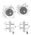
- FIG. 3 A first embodiment of a filter in accordance with the present invention is illustrated in Fig. 3. It is designed in particular for filtering environmental air in which the concentration of fine dust is lower than the safe limit (1,0 mg/m 3 ) beneath which air is breathable by those working in the environment so that ducts designed for taking dusty air directly from the sources of such dust (textile machines et cetera) and inputting it in the filter inlet are not necessary.
- the filter comprises the following items.
- Fig. 4 shows a view of the device of Fig. 3 cross sectioned along a vertical plane carried along the axis of the cylindrical shaft 4 with the cross section assuming the suction mouths 3 and 3' arranged in a vertical position. It shows a tapered shape of said mouths and the outlet direction 6 of the fine dust collected by the suction mouths 3 and 3' as well as a motor 7 for driving the shaft 4 and two supports 8 for said shaft.
- the filter of the example of figures 3 and 4 lends itself to installation directly in the environment whose air is to be filtered.
- the filter is to be installed outside said environment it is necessary to provide a duct for carrying the dusty air to the filter.
- FIGS. 5 and 6 show how in this case the filter of figures 3 and 4 must be integrated.
- these figures show the terminal part of two ducts 9 and 9' for carrying the dusty air to the filter.
- FIGS. 7 and 8 show a dual solution of the filter of figures 5 and 6.
- a single duct 10 and two ducts 11 and 11' for filtered air outlet are used with associated exhausters not shown in the figures.
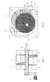
- a second embodiment of a filter in accordance with the present invention is shown in figures 9, 10 and 11. It is especially designed for filtering the air of working environments in which it is necessary to install exhaust ducts designed to take the dust and fiber waste directly from their sources such as textile machines, clipping machines et cetera. This dust is made up in large part of coarse dust and waste and only for a smaller part (for example 5%) of fine dust.
- the filter comprises as the main component illustrated in Fig. 9 the following items:
- the above mentioned characterization of the dusty air inlet opening 13 located in the margin of the filter chamber surface and shaped in such a manner as to create an entering dusty air flow tangent to the curved surface of the chamber and directed at a right angle to the direction of the filter chamber conformation cylinder axis is directed to create in the filter chamber a cyclonic movement of the dusty air so that the coarser dust and waste particles due to the effect of the centrifugal force to which they are subject are taken behind the cylindrical shell of the chamber and can be sucked in by the end of the suction mouth near said shell.
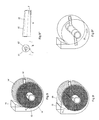
- Fig. 9' concerns the upper part of the cylindrical shell of the filter chamber 12 immediately near the mouth 13 which is a part which instead of being curved as in Fig. 9 is made with two flat surfaces 23 and 24 tangent to the original curved part.
- This variant is a construction simplification which however does not noticeably compromise the cyclonic movement of the dusty air inside the chamber.
- Fig. 9"' shows a preferred embodiment of the exhaust mouth usable in the chamber of figures 9 and 9'.
- the right-hand part of Fig. 9"' shows a front view of the suction mouth shown in Fig. 9"' while the left-hand part shows a view from the right.
- the arrow indicates the direction of running of the mouth along the filtering diaphragm.
- the suction mouth consists of two tubes t1 and t2 fitted one in the other and of which the outer one has a slightly truncated cone shape and the inner one a virtually cylindrical shape.
- the outer tube is designed to suck fine dust and has its larger diameter end leading to the cylindrical suction duct (duct 16 of figures 9 and 9') and is also open laterally through a slot "f" provided with a mouth designed to run near the filtering diaphragm "s".
- the inner tube is designed for suction of the coarser dust and has one end entering the cylindrical suction duct and the other end designed to run close to the cylindrical surface of the filter chamber.
- Fig. 9 provides that the suction mouths 15 and 15' can be closed in the terminal part opposite the cylindrical shell of the filter chamber and that the fibers and coarse waste circulating behind the cylindrical shell and which are no longer collected by said terminal part are sucked in by a purposeful suction duct whose inlet to the filter chamber consists of a hole 25 located in the lower part of the bottom of the shell.
- FIG. 9 the main component of figures 9 or 9' in which are provided two filtering diaphragms 14 and 14' can be located within a housing designed to convey the clean air issueing from the filtering diaphragms to an outlet duct.
- FIG. 10 An example of said main duct located within an associated housing is illustrated diagrammatically in figures 10 and 11.
- Fig. 9 the component of Fig. 9 is located within a boxed body 17 so as to create two chambers 18 and 18' beside the filtering diaphragms 14 and 14' i.e. side chambers into which clean air coming out of the diaphragms is let. If said chambers 18 and 18' are separated it is necessary to provide two openings 20 and 20' for outlet of clean air, i.e. one for each side chamber. If the side chambers 18 and 18' are mutually communicating above and below the cylindrical chamber the clean air can be conveyed into a single outlet opening, i.e. opening 19 shown in broken lines in Fig. 10.
- Fig. 11 shows a view of the device of Fig. 10 cross sectioned along a vertical plane conducted along the axis of the cylindrical shaft 16 which is a cross section assuming the suction mouths 15 and 15' arranged in a cylindrical shape.
- the outer tube is designed to suck fine dust and has its larger diameter end leading to the cylindrical suction duct (duct 16 of figures 9 and 9') and is also open laterally through a slot "f" provided with a mouth designed to run near the filtering diaphragm "s".
- the inner tube is designed for suction of the coarser dust and has one end entering the cylindrical suction duct and the other end designed to run close to the cylindrical surface of the filter chamber.
- Fig. 9 provides that the suction mouths 15 and 15' can be closed in the terminal part opposite the cylindrical shell of the filter chamber and that the fibers and coarse waste circulating behind the cylindrical shell and which are no longer collected by said terminal part are sucked in by a purposeful suction duct whose inlet to the filter chamber consists of a hole 25 located in the lower part of the bottom of the shell.
- FIG. 9 the main component of figures 9 or 9' in which are provided two filtering diaphragms 14 and 14' can be located within a housing designed to convey the clean air issueing from the filtering diaphragms to an outlet duct.
- FIG. 10 An example of said main duct located within an associated housing is illustrated diagrammatically in figures 10 and 11.
- Fig. 9 the component of Fig. 9 is located within a boxed body 17 so as to create two chambers 18 and 18' beside the filtering diaphragms 14 and 14' i.e. side chambers into which clean air coming out of the diaphragms is let. If said chambers 18 and 18' are separated it is necessary to provide two openings 20 and 20' for outlet of clean air, i.e. one for each side chamber. If the side chambers 18 and 18' are mutually communicating above and below the cylindrical chamber the clean air can be conveyed into a single outlet opening, i.e. opening 19 shown in broken lines in Fig. 10.
- Fig. 11 shows a view of the device of Fig. 10 cross sectioned along a vertical plane conducted along the axis of the cylindrical shaft 16 which is a cross section assuming the suction mouths 15 and 15' arranged in a vertical cross section. It shows a tapered conformation of said mouths and the presence of a motor 21 for operation of the shaft 16 and the direction 22 of outlet of the dust collected by the suction mouths 15 and 15'.
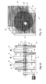
- figures 12 and 13 concern a variant of the filter of figures 10-11 to be used when high filtration efficiency is necessary.
- the machines shown in figures 1 and 2 have generally a filtering efficiency allowing treatment of dusty air having a maximum entering air dustiness of approximately 60 mg/m 3 . It follows that when the dustiness of the entering air taken directly at the points of origin of the dust, i.e. on machines such as for example in the hair-cutting or fiber-cutting zones of the teaseling or shearing machines, noticeably exceeds said maximum the machines of figures 1 and 2 require adoption of another filtration step downstream of the machines with resulting considerably increased costs and space occupied by the installation.
- the filter shown differs from that of figures 10 and 11 basically in that in place of the outlets 20 and 20' of figures 10 and 11 the two sides of the filter housing which are beside the internal filtering diaphragms are used for outlet of the filtered air subject to installation on said two sides of two external filtering diaphragms 23 and 24 with their suction mouths 25 and 26 from which to expel the filtered air.
- the in-coming dusty air undergoes two filtering stages with a resulting increase in filtering efficiency.
- FIG. 10 and 11 Another variant of the solution of figures 10 and 11 is that instead of using as in figures 10 and 11 a single outlet for the dust taken from the filtering diaphragms it is preferred to use an outlet 27 for the fine and coarse dust taken from the internal diaphragms separate from the outlets 28 and 28' of the fine dust taken by the external diaphragms to help the operations of separation of the fine dust from the coarse generally provided for the dust leaving a filter.
- the following are provided:
- Fig. 14 shows for example a filter with four filtering diaphragms obtainable by placing side-by-side two filter units similar to that of Fig. 4 and in Fig. 15 is shown for example a filter with four filtering diaphragms obtainable by placing side-by-side two filter units similar to that of Fig. 11.
- Fig. 18 shows a variant for the means adopted in the above examples to prevent passage of dust in the crack between the filtering diaphragm and the rotating shaft supporting the suction mouths. Indeed, as shown in Fig. 17, which is an enlargement of the detail 32 of Fig. 16 reproducing in turn a detail of Fig. 4, in the above examples an annular gasket 33 - for example, of felt - was adopted to prevent passage of dust.
- Fig. 18 aims at avoiding any possible danger of insufficient seal of the gasket 33 by eliminating it and adopting in its place a tube or sleeve 34 with inside diameter greater than the outside diameter of the rotating tube 4 and fitted over same in the section included between the sides of the filtering diaphragms from which filtered air issues and welded at its ends to the walls 35 in which the filtering diaphragms are fitted.
Landscapes
- Chemical & Material Sciences (AREA)
- Chemical Kinetics & Catalysis (AREA)
- Filtering Of Dispersed Particles In Gases (AREA)
Priority Applications (1)
| Application Number | Priority Date | Filing Date | Title |
|---|---|---|---|
| EP03425752A EP1533016A1 (de) | 2003-11-24 | 2003-11-24 | Filtervorrichtung zum Abtrennen von Staub aus einem luftförmigen Fluid und insbesondere zum Abscheiden von Textilstaub |
Applications Claiming Priority (1)
| Application Number | Priority Date | Filing Date | Title |
|---|---|---|---|
| EP03425752A EP1533016A1 (de) | 2003-11-24 | 2003-11-24 | Filtervorrichtung zum Abtrennen von Staub aus einem luftförmigen Fluid und insbesondere zum Abscheiden von Textilstaub |
Publications (1)
| Publication Number | Publication Date |
|---|---|
| EP1533016A1 true EP1533016A1 (de) | 2005-05-25 |
Family
ID=34429655
Family Applications (1)
| Application Number | Title | Priority Date | Filing Date |
|---|---|---|---|
| EP03425752A Withdrawn EP1533016A1 (de) | 2003-11-24 | 2003-11-24 | Filtervorrichtung zum Abtrennen von Staub aus einem luftförmigen Fluid und insbesondere zum Abscheiden von Textilstaub |
Country Status (1)
| Country | Link |
|---|---|
| EP (1) | EP1533016A1 (de) |
Cited By (2)
| Publication number | Priority date | Publication date | Assignee | Title |
|---|---|---|---|---|
| CN112007916A (zh) * | 2020-08-15 | 2020-12-01 | 江先庆 | 一种纺织机的纺织尘收集设备 |
| CN116688660A (zh) * | 2023-07-11 | 2023-09-05 | 昆山恒清净化设备科技有限公司 | 一种高效低阻袋式过滤器 |
Citations (4)
| Publication number | Priority date | Publication date | Assignee | Title |
|---|---|---|---|---|
| US3306012A (en) * | 1963-07-12 | 1967-02-28 | Svenska Flaektfabriken Ab | Cleaning device for framemounted net filters |
| US3377780A (en) * | 1966-08-04 | 1968-04-16 | W C Wiedenmann & Son Inc | Self-cleaning filter apparatus |
| DE1935153A1 (de) * | 1968-07-08 | 1970-01-15 | American Air Filter Co | Selbstreinigender Filter |
| EP1038567A1 (de) * | 1999-02-25 | 2000-09-27 | Airtec Di Grieco Annamaria | Filtervorrichtung zum Abtrennen von Staub aus einem luftförmigen Fluid und insbesondere zum Abscheiden von Textilstaub |
-
2003
- 2003-11-24 EP EP03425752A patent/EP1533016A1/de not_active Withdrawn
Patent Citations (4)
| Publication number | Priority date | Publication date | Assignee | Title |
|---|---|---|---|---|
| US3306012A (en) * | 1963-07-12 | 1967-02-28 | Svenska Flaektfabriken Ab | Cleaning device for framemounted net filters |
| US3377780A (en) * | 1966-08-04 | 1968-04-16 | W C Wiedenmann & Son Inc | Self-cleaning filter apparatus |
| DE1935153A1 (de) * | 1968-07-08 | 1970-01-15 | American Air Filter Co | Selbstreinigender Filter |
| EP1038567A1 (de) * | 1999-02-25 | 2000-09-27 | Airtec Di Grieco Annamaria | Filtervorrichtung zum Abtrennen von Staub aus einem luftförmigen Fluid und insbesondere zum Abscheiden von Textilstaub |
Cited By (2)
| Publication number | Priority date | Publication date | Assignee | Title |
|---|---|---|---|---|
| CN112007916A (zh) * | 2020-08-15 | 2020-12-01 | 江先庆 | 一种纺织机的纺织尘收集设备 |
| CN116688660A (zh) * | 2023-07-11 | 2023-09-05 | 昆山恒清净化设备科技有限公司 | 一种高效低阻袋式过滤器 |
Similar Documents
| Publication | Publication Date | Title |
|---|---|---|
| US10118115B2 (en) | Centripetal separation system for cleaning particulate-pervaded air or gas | |
| CN101061930A (zh) | 用于具有吸入能力的电动工具的带有叶片元件集尘器 | |
| CN107850325A (zh) | 纤薄型空气处理设备 | |
| JP4937189B2 (ja) | 電動空気清浄機およびその製造方法 | |
| CN118997757A (zh) | 一种采煤机机载除尘系统和采煤机 | |
| KR102206093B1 (ko) | 공기 정화 장치 | |
| JP2006514582A (ja) | 電動空気清浄機およびその製造方法 | |
| CN204672052U (zh) | 一种具有清洁功能的空气过滤装置 | |
| EP3034830B1 (de) | Motorluftvorreinigerevakuierungssystem für eine arbeitsmaschine | |
| CN101829460A (zh) | 用于制造交叉卷绕筒子的纺织机械的过滤装置 | |
| CN208097673U (zh) | 油雾分离装置 | |
| CN118718636B (zh) | 一种真空负压机用分离过滤装置 | |
| CN117482681B (zh) | 一种用于离心式通风机的进气过滤装置 | |
| CN102794287B (zh) | 多工位节能低噪除尘系统 | |
| CN117249510A (zh) | Ffu过滤模组 | |
| CN215719601U (zh) | 一种双出风的物料输送高压离心风机 | |
| KR20180070242A (ko) | 나선형 스크류 회전자 구조의 액슬리스 모터를 사용하는 진공청소기 | |
| CN210385155U (zh) | 转网除尘装置 | |
| CN208694538U (zh) | 一种粉尘呼吸器 | |
| KR102081942B1 (ko) | 청소기 | |
| CN208504595U (zh) | 一种分散式空气净化器 | |
| CN119793101B (zh) | 烟尘循环净化装置 | |
| CN108296023B (zh) | 一种节能环保旋转水处理空气净化器 | |
| CN120678357A (zh) | 一种采用内置气流预处理结构的便携式一体吹吸结构 | |
| CN215462855U (zh) | 一种移动式烟尘净化器 |
Legal Events
| Date | Code | Title | Description |
|---|---|---|---|
| PUAI | Public reference made under article 153(3) epc to a published international application that has entered the european phase |
Free format text: ORIGINAL CODE: 0009012 |
|
| AK | Designated contracting states |
Kind code of ref document: A1 Designated state(s): AT BE BG CH CY CZ DE DK EE ES FI FR GB GR HU IE IT LI LU MC NL PT RO SE SI SK TR |
|
| AX | Request for extension of the european patent |
Extension state: AL LT LV MK |
|
| 17P | Request for examination filed |
Effective date: 20050708 |
|
| AKX | Designation fees paid |
Designated state(s): AT BE BG CH CY CZ DE DK EE ES FI FR GB GR HU IE IT LI LU MC NL PT RO SE SI SK TR |
|
| 17Q | First examination report despatched |
Effective date: 20060718 |
|
| GRAP | Despatch of communication of intention to grant a patent |
Free format text: ORIGINAL CODE: EPIDOSNIGR1 |
|
| STAA | Information on the status of an ep patent application or granted ep patent |
Free format text: STATUS: THE APPLICATION IS DEEMED TO BE WITHDRAWN |
|
| 18D | Application deemed to be withdrawn |
Effective date: 20070601 |