EP1532881A2 - Method and apparatus for producing a wrapper-free filter rod of the tobacco industry - Google Patents
Method and apparatus for producing a wrapper-free filter rod of the tobacco industry Download PDFInfo
- Publication number
- EP1532881A2 EP1532881A2 EP04024223A EP04024223A EP1532881A2 EP 1532881 A2 EP1532881 A2 EP 1532881A2 EP 04024223 A EP04024223 A EP 04024223A EP 04024223 A EP04024223 A EP 04024223A EP 1532881 A2 EP1532881 A2 EP 1532881A2
- Authority
- EP
- European Patent Office
- Prior art keywords
- format
- filter
- strand
- strip
- filter material
- Prior art date
- Legal status (The legal status is an assumption and is not a legal conclusion. Google has not performed a legal analysis and makes no representation as to the accuracy of the status listed.)
- Withdrawn
Links
Images


Classifications
-
- A—HUMAN NECESSITIES
- A24—TOBACCO; CIGARS; CIGARETTES; SIMULATED SMOKING DEVICES; SMOKERS' REQUISITES
- A24D—CIGARS; CIGARETTES; TOBACCO SMOKE FILTERS; MOUTHPIECES FOR CIGARS OR CIGARETTES; MANUFACTURE OF TOBACCO SMOKE FILTERS OR MOUTHPIECES
- A24D3/00—Tobacco smoke filters, e.g. filter-tips, filtering inserts; Filters specially adapted for simulated smoking devices; Mouthpieces for cigars or cigarettes
- A24D3/02—Manufacture of tobacco smoke filters
- A24D3/0204—Preliminary operations before the filter rod forming process, e.g. crimping, blooming
- A24D3/0208—Cutting filter materials
-
- A—HUMAN NECESSITIES
- A24—TOBACCO; CIGARS; CIGARETTES; SIMULATED SMOKING DEVICES; SMOKERS' REQUISITES
- A24D—CIGARS; CIGARETTES; TOBACCO SMOKE FILTERS; MOUTHPIECES FOR CIGARS OR CIGARETTES; MANUFACTURE OF TOBACCO SMOKE FILTERS OR MOUTHPIECES
- A24D3/00—Tobacco smoke filters, e.g. filter-tips, filtering inserts; Filters specially adapted for simulated smoking devices; Mouthpieces for cigars or cigarettes
- A24D3/02—Manufacture of tobacco smoke filters
- A24D3/0229—Filter rod forming processes
- A24D3/0233—Filter rod forming processes by means of a garniture
Definitions
- the invention relates to a method for producing a wrapping material strip-free Filter strand of tobacco processing Industry, where filter material is applied to a format tape and is formed in a formatting device to the filter strand, wherein the filter strand in the format device or in the conveying direction the filter material downstream of the format device with Energy is applied to a composite of the filter material to reach.
- the invention further relates to a device for producing a tobacco-processing cladding strip-free filter strand Industry comprising a format device in which a format tape is movable, the finer to filter material comprising fibers Length is windable.
- the invention further relates to a format device of the tobacco processing Industry comprising a sub-format and an upper format, wherein the format device has an inlet region and wherein the format device is designed to be a format tape, the by the format device is movable to material, in particular Filter material to wrap the tobacco processing industry.
- a corresponding method and a corresponding device are known from US-A-3,377,220.
- Filteracetattow which exists in an endless form, crushed in a corresponding device and means an air stream an air-permeable format tape in a format device fed.
- In the area of the format device becomes Steam added to the filter material to make a connection of the filter material to accomplish.
- This object is achieved by a method for producing a tobacco-processing cladding strip-free filter strand Industry, where filter material applied to a format tape is formed and in a formatting device to the filter strand with the filter strand in the format device or in Conveying direction of the filter material downstream of the format device is energized to a composite of the filter material to reach, and wherein the filter material upstream of the Step of applying to the format tape substantially completely is isolated.
- the filter materials preferably fibers of finite length include, are essentially completely separated.
- the transporting of the separated fibers is preferably done by means of a stream of air, so that the isolated fibers, without Fiber groups to form, can be transported.
- the separation happens by means of an air flow. This will the degree of separation very high.
- the filter materials may correspond to those mentioned in the Patent applications are disclosed. It can also filter materials Find use, for example, in the European Patent application with the file number 03 004 594.2 the Applicant are disclosed. These are in particular Multi-component fibers having a length between 0.5 mm and 30 mm and preferably between 2 mm and 8 mm and in particular preferably between 3 mm and 6 mm. They are preferably a core is provided in the multi-component fiber and a corresponding shell, which have different material, wherein the shell material has a lower melting point than having the core material. There may also be other filter materials such as activated carbon granules, for example, or cellulose fibers.
- the disclosure content of the European patent application with the file number 03 004 594.2 should also fully included in the disclosure of this patent application be.
- a wrapping material strip-free filter strand is in particular a filter strand understood that not with a wrapping material strip is surrounded.
- a wrapping material strip For example, it is a filter paper strip.
- a wrapping material strip-free filter strand is thus a Filter strand, the no wrapping material strip, in particular has no filter paper strip.
- a fleece comprising the filter material, which is subsequently formed
- the format tape is stored is the homogeneity of the formed Filter strand increased.
- the fleece is expediently in formed a Saugstrangier.
- the Saugstrangadder points at least one suction belt on which the fleece is aufauert.
- the applied on the format tape Filter material by means of at least one beveled disc is preformed. This makes it very evenly and with appropriate low friction reduce the cross section of the filter material or the format tape according to the filter material wrap or partially wrap, making an effective manufacturing process is possible.
- two discs are used, their chamfers border each other in particular. If the Slices are swash plates, is a particularly homogeneous filter strand formation possible.
- the energy is to connect the fibers microwave energy or hot air.
- a special fast manufacturing process is given when after loading with energy the filter strand is cooled.
- the handling properties of cut-to-length filter elements be improved by the strand with a curable Coat is provided from a liquid material.
- an outer skin is applied after production of the filter strand. This happens, for example, by dipping or spraying with a hardenable material, such as hot melt adhesive, starchy Glue, polypropylene or similar.
- a device for producing a tobacco-processing cladding strip-free filter strand Industry comprising a format device, solved, in a format tape is movable, comprising the filter material Fibers of finite length can be wound, wherein a Aufschauervoriques is provided upstream of the format device, by means of the substantially completely separated fibers to a nonwoven are aufschauerbar.
- the device according to the invention can without a wrapping material strip feeding device be designed.
- Corresponding is none Hüllmaterial micvoriques necessary.
- the format band borders thus directly to the filter material on the format tape can be applied.
- the device according to the invention can be a very uniform and homogeneous filter strand are produced.
- the Aufschauervoriques comprises a Saugstrangrawer, which preferably has at least one suction belt. If at least one beveled in the area of the format device Slice is provided, can be a very uniform preforming the filter strand or the fleece allows his.
- the term “pane” also includes the term “pane” Role.
- the chamfered disk is preferably designed to rotate, wherein the circumference of the disc in the conveying direction of the format strip or the filter material moves.
- the chipped slice serves to preform the web for the final formation of the Filter strand in the format device.
- the chamfer is preferably at least partially circular or elliptical, preferably provided a quarter circle or aêtellipse is.
- Particularly preferred is an embodiment in which two chamfered discs are provided, in particular the same Rotate rotation axis and their chamfers adjoin each other. If at least one disc is a swash plate and preferably both discs are swash plates, is particularly effective a preforming of the web possible.
- the swash plates are preferably aligned in the conveying direction inclined to each other.
- a swash plate is an oblique within the scope of the invention Asked disc that is not at right angles to the driving them Axis is arranged.
- a unit supplying energy to the filter material is provided is.
- This unit is preferably in the range of the format device arranged.
- the energy is in the form of microwaves or hot air can be supplied.
- the filter properties of the filter strand can be improved when a sheath device is provided by means of the Filter strand is providable with an outer skin.
- a very effective one and uniform filter stranding is possible when the Width of the format tape at least equal to the circumference of forming filter strand is. If the width is equal to the circumference of the is to form a filter strand, is a filter strand formation with a very small seam possible. At a width greater than the circumference is to be formed of the filter strand, an overlap happens of the format tape in the format device.
- a format device of the tobacco processing Industry including a sub-format and an upper format solved, wherein the format device has an inlet region and wherein the format device is configured such that a format tape that is movable by the format device to Material, in particular filter material, the tobacco processing industry can be wound, wherein in the inlet region a rotatably mounted Disc pair is provided which is adapted to at least to bend a part of the format band progressively.
- the format device according to the invention is a very uniform strand formation possible.
- the pair of discs is a pair of swash plates.
- the axes of rotation of the discs coaxial.
- the Slices provided a common axis of rotation.
- the chamfer is a pitch circle, in particular a quarter circle. If one in cross-section elliptical Filter strand is desired, the chamfer can at least a part of a Ellipse include, in particular a quarter ellipse.
- the object is further achieved by the use of a swash plate pair in the range of a format device of tobacco processing Industry for bending a format tape solved.
- a swash plate pair in the range of a format device of tobacco processing Industry for bending a format tape solved.
- Fig. 1 shows a schematic side view of an inventive Stranding machine 1.
- the stranding machine 1 substantially corresponds in the European patent application with the file number 03 007 675.6 and the European patent application with the Reference 03 007 672.3 disclosed stranding machine, wherein in Difference to the strand machines disclosed therein a filter strand in the filter rod machine 1 shown in Fig. 1 without Wrapping strip can be produced.
- the remaining on the suction belt 13 fiber layer 15 ' is compressed after leveling in a pressing device 17.
- the Pressing device is in this embodiment as a conveyor belt formed, which includes a corresponding press roller.
- the Conveyor belt is or the press roller is substantially in the conveying direction emotional. This is in Fig. 1 counterclockwise.
- the transfer of the densified fiber layer 15 "of the suction belt conveyor 14 the format device 20 is in this embodiment a fiber fleece.
- suction air is used by a suction air connection 18 acts on the suction belt 13.
- Compressed air connection 19 provided by means of which the fiber layer 15 "is detached from the suction belt 13 and on the format tape 23 of the format device 20 is applied.
- the format device 20 comprises a format console 21, a format set 22 and, as already mentioned, the format tape 23. Die Further components of the format device 20 are described below described in more detail.
- the formed in the format device 20 Filter strand 33 is optionally in a Besprühü 34 with, for example Polypropylene sprayed to a coat or an outer skin to provide on the filter strand 33. Subsequently, the Filter strand 33 of a cutting device 35 supplied in the filter rods 36 are cut off from the filter strand 33.
- Fig. 2 shows a schematic side view of the invention Strand machine or a part of the invention Stranding machine in direction A of Fig. 1.
- Fig. 2 is the separation the fibers 10 and the supply of the separated fibers 10 to Saugstrangier 14 shown schematically.
- the isolation corresponds to that, as for example in the European Patent applications with the file number 03 007 675.6 and 03 007 672.3. It can be any kind of in both European Patent applications mentioned singling use Find.
- a storage shaft 24 fibers are introduced.
- Two feed rollers 25 promote the fibers in the effective range of a transport roller 27, which deflects the fibers from the stowage bay.
- the separating device 26 are also separating rollers 28 are provided, which are in operative connection with a grid 29. through the transport air, which is not shown schematically in Fig. 2 (This will be to the above-mentioned European patent applications ), And the separating rollers 28 become fibers that have been essentially completely separated promoted by the grid 29, so that in the area of the fluidized bed 12 predominantly scattered fiber prevail.
- the isolated fibers also by means of transport air in particular by substantially continuous acceleration isolated the suction belt 13 of the suction belt conveyor 14th fed. Excess transport air is in the exhaust 30 or in a rolling room, not shown, of the fluidized bed 12th dissipated.
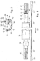
- FIG. 3 shows a top view of a format device according to the invention, the component of the strand machine 1 according to the invention is.
- the format set 22 comprises an inlet chamber 41, a sub-format 46 and an upper format 47, see also the 4 is a microwave unit 31, a cooling unit 32 and an outlet chamber 45 is provided.
- the format tape 23 is counterclockwise in the conveying direction 50 'moves. Before the inlet chamber 41 and after the outlet chamber 45, the format tape 23 is being guided. In the inlet chamber 41, the format tape 23 'laterally increasingly upward shaped round. At the end of the inlet chamber 41, the upwards curved sides of the format strip 23 'by a pair of swash plates 42 and increasingly bent inwards. To Leaving the effective range of the swash plate pair 42 is the Format band 23 'already almost completely round shaped. Between the sub-format 46 and the upper format 47 is the full Circular forming of the 23 "format tape The side edges of the format tape 23 "either face or overlap on impact.
- the format tape 23 is as wide as the size of the too generating filter strand.
- Fig. 5 is a schematic sectional view taken along the Section A-A of Fig. 4 shown. In particular, they are the swash plates 42 clearly recognizable, in the lower part of the strand cross-section 49 at least partially generate by the respective chamfer 51.
- 6 is a schematic cross-sectional view along of the section B-B of Fig. 4. At this point is the filter strand already fully formed. The filter strand or fibers in However, the filter strand do not have a completely solid Composite formed.
- the fiber layer 15 " is in the region of the inlet chamber 41 of Saugstrang detergenter 14 passed to the format tape 23 '.
- the 23" format tape holds and leads the fiber strand 33 through the microwave unit 31.
- Binding fibers are in particular bicomponent fibers in question, which include a core and a jacket, wherein the sheath comprises a lower melting material than the sheath Core.
- the European patent application with the application number 03 004 594.2 of the Applicant.
- Suitable filler fibers are, for example, cellulose fibers. These fibers are also in the aforementioned European patent application disclosed accordingly.
- the advantage of using a microwave unit 31 is the low heating of the Filter strand 33, allowing a format cooling, a contact cooling is sufficient.
- the fiber strand 33 After the microwave unit 31, according to the principle of contact cooling can be configured, the fiber strand 33 by a Cooling unit 32 out.
- cooling water is through the upper format 47 and sub-format 46 passed. There they cool and harden fused areas.
- the fiber strand 33 is then cured.
- the type, material and condition of the format tape 23 are chosen so that a fusion of binding fibers with the Format tape is not possible.
- the format tape permeable to air.
- the format tape 23 "in 23 'and then 23 remains the cured fiber strand 33 in round Shape. It can also be a fiber strand 33 in oval or elliptical Form to be formed. This is the format device or form fitting 22 corresponding oval or elliptical form.
- the format strip 23 ' is the fiber strand up and to the side free and promotes him to the cutting device 35th There is the cured Fiber strand 33 cut into filter rods 36. Before the Cutting the filter rods 36 may around the fiber strand 33 in a Spray unit 34, which may also be a dip, is a wrapping material be applied, such as a hot melt adhesive.
- the chamfer 51 of the swash plates is according to the desired Form configured of the filter strand to be formed.
Abstract
Description
Die Erfindung betrifft ein Verfahren zur Herstellung eines umhüllungsmaterialstreifenfreien Filterstrangs der tabakverarbeitenden Industrie, wobei Filtermaterial auf ein Formatband aufgebracht wird und in einer Formatvorrichtung zu dem Filterstrang geformt wird, wobei der Filterstrang in der Formatvorrichtung oder in Förderrichtung des Filtermaterials stromabwärts der Formatvorrichtung mit Energie beaufschlagt wird, um einen Verbund des Filtermaterials zu erreichen.The invention relates to a method for producing a wrapping material strip-free Filter strand of tobacco processing Industry, where filter material is applied to a format tape and is formed in a formatting device to the filter strand, wherein the filter strand in the format device or in the conveying direction the filter material downstream of the format device with Energy is applied to a composite of the filter material to reach.
Die Erfindung betrifft ferner eine Vorrichtung zur Herstellung eines umhüllungsmaterialstreifenfreien Filterstrangs der tabakverarbeitenden Industrie umfassend eine Formatvorrichtung, in der ein Formatband bewegbar ist, das um Filtermaterial umfassend Fasern endlicher Länge wickelbar ist. The invention further relates to a device for producing a tobacco-processing cladding strip-free filter strand Industry comprising a format device in which a format tape is movable, the finer to filter material comprising fibers Length is windable.
Die Erfindung betrifft ferner eine Formatvorrichtung der tabakverarbeitenden Industrie umfassend ein Unterformat und ein Oberformat, wobei die Formatvorrichtung einen Einlaufbereich aufweist und wobei die Formatvorrichtung ausgestaltet ist, um ein Formatband, das durch die Formatvorrichtung bewegbar ist, um Material, insbesondere Filtermaterial, der tabakverarbeitenden Industrie zu wickeln.The invention further relates to a format device of the tobacco processing Industry comprising a sub-format and an upper format, wherein the format device has an inlet region and wherein the format device is designed to be a format tape, the by the format device is movable to material, in particular Filter material to wrap the tobacco processing industry.
Ein entsprechendes Verfahren und eine entsprechende Vorrichtung sind aus der US-A-3 377 220 bekannt. In diesem Dokument, vergleiche insbesondere Fig. 11 und die dazugehörige Figurenbeschreibung, wird Filteracetattow, das in einer endlosen Form vorliegt, in einer entsprechenden Vorrichtung zerkleinert und mittels eines Luftstroms einem luftdurchlässigen Formatband in einer Formatvorrichtung zugeführt. Im Bereich der Formatvorrichtung wird Dampf dem Filtermaterial hinzugeführt, um eine Verbindung des Filtermaterials zu schaffen.A corresponding method and a corresponding device are known from US-A-3,377,220. In this document, compare in particular FIG. 11 and the associated description of the figures, becomes Filteracetattow, which exists in an endless form, crushed in a corresponding device and means an air stream an air-permeable format tape in a format device fed. In the area of the format device becomes Steam added to the filter material to make a connection of the filter material to accomplish.
Gegenüber diesem Stand der Technik ist es Aufgabe der vorliegenden Erfindung, ein Verfahren und eine Vorrichtung anzugeben, mittels der ein sehr homogener Strang eines Materials der tabakverarbeitenden Industrie, insbesondere ein Filterstrang, gebildet werden kann.Compared to this prior art, it is an object of the present invention Invention to provide a method and an apparatus by means of a very homogenous strand of tobacco processing material Industry, in particular a filter strand, are formed can.
Gelöst wird diese Aufgabe durch ein Verfahren zur Herstellung eines umhüllungsmaterialstreifenfreien Filterstrangs der tabakverarbeitenden Industrie, wobei Filtermaterial auf ein Formatband aufgebracht wird und in einer Formatvorrichtung zu dem Filterstrang geformt wird, wobei der Filterstrang in der Formatvorrichtung oder in Förderrichtung des Filtermaterials stromabwärts der Formatvorrichtung mit Energie beaufschlagt wird, um einen Verbund des Filtermaterials zu erreichen, und wobei das Filtermaterial stromaufwärts des Schritts des Aufbringens auf das Formatband im wesentlichen vollständig vereinzelt wird.This object is achieved by a method for producing a tobacco-processing cladding strip-free filter strand Industry, where filter material applied to a format tape is formed and in a formatting device to the filter strand with the filter strand in the format device or in Conveying direction of the filter material downstream of the format device is energized to a composite of the filter material to reach, and wherein the filter material upstream of the Step of applying to the format tape substantially completely is isolated.
Durch die im wesentlichen vollständige Vereinzelung des Filtermaterials ist eine sehr homogene Filterstrangbildung möglich.By essentially complete separation of the filter material is a very homogeneous stranding possible.
Hierzu wird insbesondere auf die europäische Patentanmeldung EP 03 007 675.6, die am 03.04.2003 angemeldet wurde und die europäische Patentanmeldung EP 03 007 672.3 mit demselben Anmeldetag verwiesen. Beide Anmeldungen sind von der Anmelderin der vorliegenden Patentanmeldung. Der Offenbarungsgehalt dieser Patentanmeldungen soll vollumfänglich in der vorliegenden Patentanmeldung aufgenommen sein. Es ist erfindungsgemäß wesentlich, dass die Filtermaterialien, die vorzugsweise Fasern endlicher Länge umfassen, im wesentlichen vollständig vereinzelt werden. Hierbei ist das Erscheinungsbild eines Stromes aus vereinzelten Fasern ähnlich einem Schneesturm, also einem Strom von Fasern, der eine homogene statistische Verteilung der Fasern sowohl räumlich als auch zeitlich aufweist. Insbesondere bedeutet das im wesentlichen vollständige Vereinzeln der Fasern, dass im wesentlichen keine Gruppen von Fasern, die miteinander verbunden sind, mehr vorhanden sind. Erst nach dem Vereinzeln der Fasern wird wieder ein Verbund der Fasern, beispielsweise dann in dem Filterstrang, hergestellt. Hierdurch ist es möglich, einen Filterstrang herzustellen, der keine Brücken oder Hohlräume enthält.For this purpose, in particular the European patent application EP 03 007 675.6, which was filed on 03.04.2003 and the European Patent application EP 03 007 672.3 with the same filing date directed. Both applications are filed by the applicant of the present patent application. The disclosure of these patent applications is intended in its entirety in the present patent application be included. It is essential according to the invention that the filter materials, preferably fibers of finite length include, are essentially completely separated. Here is the appearance of a stream of isolated fibers similar a blizzard, that is, a stream of fibers, the one homogeneous statistical distribution of fibers both spatially and also temporally. In particular, this essentially means complete separation of the fibers, that essentially no Groups of fibers that are interconnected, more present are. Only after the separation of the fibers is a composite again the fibers, for example, then in the filter strand produced. This makes it possible to produce a filter strand, the contains no bridges or cavities.
Das Transportieren der vereinzelten Fasern geschieht vorzugsweise mittels eines Luftstromes, so dass die vereinzelten Fasern, ohne Fasergruppen zu bilden, transportiert werden können. Vorzugsweise geschieht das Vereinzeln mittels eines Luftstromes. Hierdurch wird der Vereinzelungsgrad sehr hoch.The transporting of the separated fibers is preferably done by means of a stream of air, so that the isolated fibers, without Fiber groups to form, can be transported. Preferably the separation happens by means of an air flow. This will the degree of separation very high.
Die Filtermaterialien können denjenigen entsprechen, die in den genannten Patentanmeldungen offenbart sind. Es können auch Filtermaterialien Verwendung finden, die beispielsweise in der europäischen Patentanmeldung mit dem Aktenzeichen 03 004 594.2 der Anmelderin offenbart sind. Hierbei handelt es sich insbesondere um Mehrfachkomponentenfasern, die eine Länge zwischen 0,5 mm und 30 mm aufweisen und vorzugsweise zwischen 2 mm und 8 mm und insbesondere vorzugsweise zwischen 3 mm und 6 mm. Es sind vorzugsweise ein Kern in der Mehrfachkomponentenfaser vorgesehen und eine entsprechende Hülle, die unterschiedliches Material aufweisen, wobei das Hüllmaterial einen niedrigeren Schmelzpunkt als das Kernmaterial aufweist. Es können auch andere Filtermaterialien hinzugefügt werden, wie Aktivkohlegranulat beispielsweise oder Zellulosefasern. Der Offenbarungsgehalt der europäischen Patentanmeldung mit dem Aktenzeichen 03 004 594.2 soll auch vollumfänglich in den Offenbarungsgehalt dieser Patentanmeldung aufgenommen sein.The filter materials may correspond to those mentioned in the Patent applications are disclosed. It can also filter materials Find use, for example, in the European Patent application with the file number 03 004 594.2 the Applicant are disclosed. These are in particular Multi-component fibers having a length between 0.5 mm and 30 mm and preferably between 2 mm and 8 mm and in particular preferably between 3 mm and 6 mm. They are preferably a core is provided in the multi-component fiber and a corresponding shell, which have different material, wherein the shell material has a lower melting point than having the core material. There may also be other filter materials such as activated carbon granules, for example, or cellulose fibers. The disclosure content of the European patent application with the file number 03 004 594.2 should also fully included in the disclosure of this patent application be.
Unter einem umhüllungsmaterialstreifenfreien Filterstrang wird insbesondere ein Filterstrang verstanden, der nicht mit einem Umhüllungsmaterialstreifen umgeben ist. Bei einem Umhüllungsmaterialstreifen handelt es sich beispielsweise um einen Filterpapierstreifen. Ein umhüllungsmaterialstreifenfreier Filterstrang ist somit ein Filterstrang, der keinen Umhüllungsmaterialstreifen, insbesondere keinen Filterpapierstreifen aufweist.Under a wrapping material strip-free filter strand is in particular a filter strand understood that not with a wrapping material strip is surrounded. In a wrapping material strip For example, it is a filter paper strip. A wrapping material strip-free filter strand is thus a Filter strand, the no wrapping material strip, in particular has no filter paper strip.
Wenn nach der Vereinzelung des Filtermaterials zunächst ein Vlies, umfassend das Filtermaterial, gebildet wird, das anschließend auf das Formatband abgelegt wird, ist die Homogenität des gebildeten Filterstrangs erhöht. Hierbei wird das Vlies zweckmäßigerweise in einem Saugstrangförderer gebildet. Der Saugstrangförderer weist wenigstens ein Saugband auf, auf das das Vlies aufgeschauert wird. If, after the separation of the filter material, a fleece, comprising the filter material, which is subsequently formed The format tape is stored is the homogeneity of the formed Filter strand increased. Here, the fleece is expediently in formed a Saugstrangförderer. The Saugstrangförderer points at least one suction belt on which the fleece is aufauert.
Es ist besonders bevorzugt, wenn das auf dem Formatband aufgebrachte Filtermaterial mittels wenigstens einer gefasten Scheibe vorgeformt wird. Hierdurch lässt sich sehr gleichmäßig und mit entsprechend geringer Reibung der Querschnitt des Filtermaterials verringern bzw. das Formatband entsprechend um das Filtermaterial wickeln bzw. teilweise wickeln, so dass ein effektives Herstellungsverfahren ermöglicht ist. Vorzugsweise finden zwei Scheiben Verwendung, deren Fasen insbesondere aneinander grenzen. Wenn die Scheiben Taumelscheiben sind, ist eine besonders homogene Filterstrangbildung möglich.It is particularly preferred if the applied on the format tape Filter material by means of at least one beveled disc is preformed. This makes it very evenly and with appropriate low friction reduce the cross section of the filter material or the format tape according to the filter material wrap or partially wrap, making an effective manufacturing process is possible. Preferably, two discs are used, their chamfers border each other in particular. If the Slices are swash plates, is a particularly homogeneous filter strand formation possible.
In einer zweckmäßigen Ausgestaltung ist die Energie zum Verbinden der Fasern Mikrowellenenergie oder Heißluft. Ein besonders schnelles Herstellungsverfahren ist dann gegeben, wenn nach Beaufschlagung mit Energie der Filterstrang gekühlt wird. Die Handhabungseigenschaften von von dem Strang abgelängten Filterelementen werden dadurch verbessert, dass der Strang mit einem aushärtbaren Mantel aus einem flüssigen Material versehen wird. Hierbei wird nach Herstellung des Filterstrangs eine Außenhaut aufgetragen. Dieses geschieht beispielsweise durch Eintauchen oder Besprühen mit einem aushärtbaren Material, wie Schmelzkleber, stärkehaltigem Kleber, Polypropylen oder ähnlichem.In an expedient embodiment, the energy is to connect the fibers microwave energy or hot air. A special fast manufacturing process is given when after loading with energy the filter strand is cooled. The handling properties of cut-to-length filter elements be improved by the strand with a curable Coat is provided from a liquid material. in this connection an outer skin is applied after production of the filter strand. This happens, for example, by dipping or spraying with a hardenable material, such as hot melt adhesive, starchy Glue, polypropylene or similar.
Wenn anschließend zu dem vorgeschriebenen Verfahren der hergestellte Filterstrang in Filterelemente abgelängt wird, ist ein erfindungsgemäßes Herstellungsverfahren für Filterelemente angegeben.When subsequently to the prescribed procedure the manufactured Filter strand is cut to length in filter elements, is an inventive Manufacturing process for filter elements specified.
Die Aufgabe wird ferner durch eine Vorrichtung zur Herstellung eines umhüllungsmaterialstreifenfreien Filterstrangs der tabakverarbeitenden Industrie, umfassend eine Formatvorrichtung, gelöst, in der ein Formatband bewegbar ist, das um Filtermaterial umfassend Fasern endlicher Länge wickelbar ist, wobei eine Aufschauervorrichtung stromaufwärts der Formatvorrichtung vorgesehen ist, mittels der im wesentlichen vollständig vereinzelte Fasern zu einem Vlies aufschauerbar sind. Die erfindungsgemäße Vorrichtung kann ohne eine Umhüllungsmaterialstreifenzuführvorrichtung bzw. Hüllmaterialzuführvorrichtung ausgestaltet sein. Entsprechend ist auch keine Hüllmaterialfördervorrichtung notwendig. Das Formatband grenzt somit unmittelbar an das Filtermaterial, das auf das Formatband aufbringbar ist.The object is further achieved by a device for producing a tobacco-processing cladding strip-free filter strand Industry, comprising a format device, solved, in a format tape is movable, comprising the filter material Fibers of finite length can be wound, wherein a Aufschauervorrichtung is provided upstream of the format device, by means of the substantially completely separated fibers to a nonwoven are aufschauerbar. The device according to the invention can without a wrapping material strip feeding device be designed. Corresponding is none Hüllmaterialfördervorrichtung necessary. The format band borders thus directly to the filter material on the format tape can be applied.
Durch die erfindungsgemäße Vorrichtung kann ein sehr gleichmäßiger und homogener Filterstrang hergestellt werden.By the device according to the invention can be a very uniform and homogeneous filter strand are produced.
Vorzugsweise umfasst die Aufschauervorrichtung einen Saugstrangförderer, der vorzugsweise wenigstens ein Saugband aufweist. Wenn im Bereich der Formatvorrichtung wenigstens eine gefaste Scheibe vorgesehen ist, kann eine sehr gleichmäßige Vorformung des Filterstrangs bzw. des Vlieses ermöglicht sein. Im Rahmen der Erfindung umfasst der Begriff Scheibe insbesondere auch den Begriff Rolle. Die gefaste Scheibe ist vorzugsweise rotierend ausgebildet, wobei der Umfang der Scheibe sich in Förderrichtung des Formatbandes bzw. des Filtermaterials bewegt. Die gefaste Scheibe dient zur Vorformung des Vlieses zur endgültigen Ausbildung des Filterstrangs in der Formatvorrichtung.Preferably, the Aufschauervorrichtung comprises a Saugstrangförderer, which preferably has at least one suction belt. If at least one beveled in the area of the format device Slice is provided, can be a very uniform preforming the filter strand or the fleece allows his. As part of the In particular, the term "pane" also includes the term "pane" Role. The chamfered disk is preferably designed to rotate, wherein the circumference of the disc in the conveying direction of the format strip or the filter material moves. The chipped slice serves to preform the web for the final formation of the Filter strand in the format device.
Vorzugsweise ist auch eine Wirkverbindung mit dem Formatband dergestalt vorgesehen, dass das Formatband von der Fase erfasst wird und zunehmend nach innen gebogen wird. Die Form der Fase ist vorzugsweise wenigstens teilweise kreisförmig oder elliptisch, wobei vorzugsweise ein Viertelkreis bzw. eine Viertelellipse vorgesehen ist. Besonders bevorzugt ist eine Ausgestaltung, bei der zwei gefaste Scheiben vorgesehen sind, die insbesondere um die gleiche Rotationsachse rotieren und deren Fasen aneinander grenzen. Wenn wenigstens eine Scheibe eine Taumelscheibe ist und vorzugsweise beide Scheiben Taumelscheiben sind, ist besonders effektiv eine Vorformung des Vlieses möglich. Die Taumelscheiben sind vorzugsweise in Förderrichtung zueinander geneigt ausgerichtet. Eine Taumelscheibe ist im Rahmen der Erfindung eine schräg gestellte Scheibe, die nicht im rechten Winkel auf der sie antreibenden Achse angeordnet ist.Preferably also an operative connection with the format tape provided such that the format tape detected by the chamfer becomes and is increasingly bent inward. The shape of the chamfer is preferably at least partially circular or elliptical, preferably provided a quarter circle or a Viertelellipse is. Particularly preferred is an embodiment in which two chamfered discs are provided, in particular the same Rotate rotation axis and their chamfers adjoin each other. If at least one disc is a swash plate and preferably both discs are swash plates, is particularly effective a preforming of the web possible. The swash plates are preferably aligned in the conveying direction inclined to each other. A swash plate is an oblique within the scope of the invention Asked disc that is not at right angles to the driving them Axis is arranged.
Eine effektive Verbindung der Filtermaterialien ist dann möglich, wenn eine dem Filtermaterial Energie zuführende Einheit vorgesehen ist. Diese Einheit ist vorzugsweise im Bereich der Formatvorrichtung angeordnet. Vorzugsweise ist die Energie in Form von Mikrowellen oder Heißluft zuführbar.An effective connection of the filter materials is then possible when a unit supplying energy to the filter material is provided is. This unit is preferably in the range of the format device arranged. Preferably, the energy is in the form of microwaves or hot air can be supplied.
Die Filtereigenschaften des Filterstrangs können verbessert werden, wenn eine Ummantelungsvorrichtung vorgesehen ist, mittels der der Filterstrang mit einer Außenhaut versehbar ist. Eine sehr effektive und gleichmäßige Filterstrangbildung ist dann möglich, wenn die Breite des Formatbandes wenigstens gleich dem Umfang des zu bildenden Filterstrangs ist. Sofern die Breite gleich dem Umfang des zu bildenden Filterstrangs ist, ist eine Filterstrangbildung mit einer sehr kleinen Naht möglich. Bei einer Breite, die größer als der Umfang des zu bildenden Filterstrangs ist, geschieht eine Überlappung des Formatbandes in der Formatvorrichtung.The filter properties of the filter strand can be improved when a sheath device is provided by means of the Filter strand is providable with an outer skin. A very effective one and uniform filter stranding is possible when the Width of the format tape at least equal to the circumference of forming filter strand is. If the width is equal to the circumference of the is to form a filter strand, is a filter strand formation with a very small seam possible. At a width greater than the circumference is to be formed of the filter strand, an overlap happens of the format tape in the format device.
Die Aufgabe wird ferner durch eine Formatvorrichtung der tabakverarbeitenden Industrie, umfassend ein Unterformat und ein Oberformat gelöst, wobei die Formatvorrichtung einen Einlaufbereich aufweist und wobei die Formatvorrichtung derart ausgestaltet ist, dass ein Formatband, das durch die Formatvorrichtung bewegbar ist, um Material, insbesondere Filtermaterial, der tabakverarbeitenden Industrie wickelbar ist, wobei im Einlaufbereich ein drehbar gelagertes Scheibenpaar vorgesehen ist, das ausgebildet ist, um wenigstens einen Teil des Formatbandes fortschreitend umzubiegen.The object is further achieved by a format device of the tobacco processing Industry, including a sub-format and an upper format solved, wherein the format device has an inlet region and wherein the format device is configured such that a format tape that is movable by the format device to Material, in particular filter material, the tobacco processing industry can be wound, wherein in the inlet region a rotatably mounted Disc pair is provided which is adapted to at least to bend a part of the format band progressively.
Durch die erfindungsgemäße Formatvorrichtung ist eine sehr gleichmäßige Strangbildung möglich.The format device according to the invention is a very uniform strand formation possible.
Vorzugsweise ist das Scheibenpaar ein Taumelscheibenpaar. In einer zweckmäßigen Ausgestaltung, sind die Drehachsen der Scheiben koaxial. In einer weiteren bevorzugten Ausgestaltung ist für die Scheiben eine gemeinsame Drehachse vorgesehen.Preferably, the pair of discs is a pair of swash plates. In a expedient embodiment, the axes of rotation of the discs coaxial. In a further preferred embodiment is for the Slices provided a common axis of rotation.
Wenn die Scheiben an ihren jeweiligen Umfangsflächen gefast sind, ist eine besonders effektive Vorformung des Filterstrangs möglich. Hierzu ist vorzugsweise wenigstens ein Teil der Fase ein Teilkreis, insbesondere ein Viertelkreis. Sofern ein im Querschnitt elliptischer Filterstrang gewünscht ist, kann die Fase wenigstens ein Teil einer Ellipse umfassen, insbesondere einer Viertelellipse.When the discs are chamfered at their respective peripheral surfaces, is a particularly effective preforming of the filter strand possible. For this purpose, preferably at least a part of the chamfer is a pitch circle, in particular a quarter circle. If one in cross-section elliptical Filter strand is desired, the chamfer can at least a part of a Ellipse include, in particular a quarter ellipse.
Unter Fase wird im Rahmen dieser Erfindung insbesondere eine Form der Umfangsfläche der Schreibe verstanden, die im Querschnitt keine gerade Strecke ist, die senkrecht zu wenigstens einer Stirnseite ist. Stattdessen kann eine Aushöhlung oder Ausfräsung vorliegen.Under bevel is in the context of this invention, in particular a Form of the peripheral surface of the letter understood in cross section there is no straight line perpendicular to at least one Front side is. Instead, a hollow or milled out available.
Die Aufgabe wird ferner durch die Verwendung eines Taumelscheibenpaars im Bereich einer Formatvorrichtung der tabakverarbeitenden Industrie zur Verbiegung eines Formatbandes gelöst. Vorzugsweise geschieht die Verbiegung quer zur Förderrichtung des Formatbandes.The object is further achieved by the use of a swash plate pair in the range of a format device of tobacco processing Industry for bending a format tape solved. Preferably happens the bending transverse to the conveying direction of the format strip.
Die Erfindung wird nachstehend ohne Beschränkung des allgemeinen Erfindungsgedankens anhand von Ausführungsbeispielen unter Bezugnahme auf die Zeichnungen beschrieben. Bezüglich aller im Text nicht näher erläuterten erfindungsgemäßen Einzelheiten wird ausdrücklich auf die Zeichnungen verwiesen. Es zeigen:
- Fig. 1
- eine schematische Seitenansicht einer erfindungsgemäßen Strangmaschine,
- Fig. 2
- eine schematische Schnittdarstellung der Strangmaschine aus Fig. 1 in Richtung A der Fig. 1,
- Fig. 3
- im oberen Bereich eine schematische Draufsicht auf eine erfindungsgemäße Formatvorrichtung und im unteren Bereich zur besseren Veranschaulichung eine Draufsicht auf ein Formatband, das durch die Formatvorrichtung hindurch bewegbar ist,
- Fig. 4
- im oberen Bereich eine schematische Seitenansicht der Formatvorrichtung aus Fig. 3 und im unteren Bereich eine schematische Seitenansicht des Formatbandes aus Fig. 3,
- Fig. 5
- eine schematische Schnittdarstellung entlang des Schnitts A-A aus Fig. 4, und
- Fig. 6
- eine schematische Schnittdarstellung entlang B-B aus Fig. 4.
- Fig. 1
- a schematic side view of a strand machine according to the invention,
- Fig. 2
- 1 is a schematic sectional view of the strand machine of FIG. 1 in the direction A of FIG. 1,
- Fig. 3
- in the upper area a schematic plan view of a formatting device according to the invention and in the lower area for a better illustration a plan view of a format strip which is movable through the formatting device,
- Fig. 4
- in the upper area a schematic side view of the format device of FIG. 3 and in the lower area a schematic side view of the format strip of FIG. 3,
- Fig. 5
- a schematic sectional view along the section AA of Fig. 4, and
- Fig. 6
- a schematic sectional view along BB of Fig. 4th
Fig. 1 zeigt eine schematische Seitenansicht einer erfindungsgemäßen Strangmaschine 1. Die Strangmaschine 1 entspricht im wesentlichen der in der europäischen Patentanmeldung mit dem Aktenzeichen 03 007 675.6 und der europäischen Patentanmeldung mit dem Aktenzeichen 03 007 672.3 offenbarten Strangmaschine, wobei im Unterschied zu den dort offenbarten Strangmaschinen ein Filterstrang in der in Fig. 1 dargestellten Filterstrangmaschine 1 ohne Umhüllungsstreifen herstellbar ist.Fig. 1 shows a schematic side view of an inventive Stranding machine 1. The stranding machine 1 substantially corresponds in the European patent application with the file number 03 007 675.6 and the European patent application with the Reference 03 007 672.3 disclosed stranding machine, wherein in Difference to the strand machines disclosed therein a filter strand in the filter rod machine 1 shown in Fig. 1 without Wrapping strip can be produced.
Wie in den eben genannten europäischen Patentanmeldungen offenbart,
werden entsprechende endliche Fasern 10 vereinzelt bzw.
im wesentlichen vollständig vereinzelt und über ein Fließbett 12 in
Richtung eines Saugbandes 13 eines Saugstrangförderers 14 mittels
Transportluft in Förderrichtung 50 gefördert. Die vereinzelten
Fasern 10 werden auf dem Saugband 13 aufgeschauert und bilden
eine in Fig. 1 nach links zunehmende Faserschicht 15 im Kanal des
Saugstrangförderers 14 auf dem sich in Fig. 1 nach links bewegenden
Saugband 13. Die Faserschicht 15 nimmt in Förderrichtung 50'
zu und wird auf dem Weg in Förderrichtung 50' an dem Trimmer 16
egalisiert. Nach der Trimmung wird eine Faserschicht 15''' abgeführt.
Die an dem Saugband 13 verbleibende Faserschicht 15' wird
nach dem Egalisieren in einer Pressvorrichtung 17 verdichtet. Die
Pressvorrichtung ist in diesem Ausführungsbeispiel als ein Förderband
ausgebildet, das eine entsprechende Presswalze umfasst. Das
Förderband wird bzw. die Presswalze wird im wesentlichen in Förderrichtung
bewegt. Dieses ist in Fig. 1 entgegen dem Uhrzeigersinn.As disclosed in the aforementioned European patent applications,
appropriate
Nach der Egalisierung und Verdichtung erfolgt die Übergabe der
verdichteten Faserschicht 15" von dem Saugstrangförderer 14 auf
die Formatvorrichtung 20. Die Faserschicht ist in diesem Ausführungsbeispiel
ein Faservlies. Um die Faserschicht an dem Saugband
13 anhäufen zu lassen, wird Saugluft verwendet, die durch
einen Saugluftanschluss 18 an dem Saugband 13 wirkt. Im Bereich
der Übergabe der Faserschicht 15" zur Formatvorrichtung ist ein
Druckluftanschluss 19 vorgesehen, mittels dem die Faserschicht
15" von dem Saugband 13 abgelöst wird und auf das Formatband
23 der Formatvorrichtung 20 aufgebracht wird.After leveling and compaction, the transfer of the
densified
Die Formatvorrichtung 20 umfasst eine Formatkonsole 21, eine Formatgarnitur
22 und, wie schon erwähnt, das Formatband 23. Die
weiteren Komponenten der Formatvorrichtung 20 werden im Folgenden
näher beschrieben. Der in der Formatvorrichtung 20 gebildete
Filterstrang 33 wird optional in einer Besprüheinheit 34 mit beispielsweise
Polypropylen besprüht, um einen Mantel bzw. eine Außenhaut
an dem Filterstrang 33 vorzusehen. Anschließend wird der
Filterstrang 33 einer Schneidvorrichtung 35 zugeführt, in der Filterstäbe
36 von dem Filterstrang 33 abgeschnitten werden.The
Fig. 2 zeigt eine schematische Seitenansicht der erfindungsgemäßen
Strangmaschine bzw. eines Teils der erfindungsgemäßen
Strangmaschine in Richtung A aus Fig. 1. In der Fig. 2 ist die Vereinzelung
der Fasern 10 und die Zuführung der vereinzelten Fasern
10 zum Saugstrangförderer 14 schematisch dargestellt. Die Vereinzelung
entspricht derjenigen, wie beispielsweise in den europäischen
Patentanmeldungen mit dem Aktenzeichen 03 007 675.6 und
03 007 672.3 beschrieben. Es kann jede Art der in beiden europäischen
Patentanmeldungen genannten Vereinzelungen Verwendung
finden.Fig. 2 shows a schematic side view of the invention
Strand machine or a part of the invention
Stranding machine in direction A of Fig. 1. In Fig. 2 is the separation
the
In einem Stauschacht 24 werden Fasern eingebracht. Zwei Einzugswalzen
25 fördern die Fasern in den Wirkbereich einer Transportwalze
27, die die Fasern aus dem Stauschacht ausschlägt. In
der Vereinzelungsvorrichtung 26 sind ferner Vereinzelungswalzen
28 vorgesehen, die in Wirkverbindung mit einem Gitter 29 sind. Mittels
der Transportluft, die in Fig. 2 nicht schematisch dargestellt ist
(hierzu wird auf die vorstehend genannten europäischen Patentanmeldungen
Bezug genommen), und der Vereinzelungswalzen 28
werden Fasern, die im wesentlichen vollständig vereinzelt wurden,
durch das Gitter 29 gefördert, so dass im Bereich des Fließbettes
12 im wesentlichen vereinzelte Faser vorherrschen. Im Bereich des
Fließbettes 12 werden die vereinzelten Fasern auch mittels Transportluft
insbesondere durch im wesentlichen andauernde Beschleunigung
vereinzelt dem Saugband 13 des Saugstrangförderers 14
zugeführt. Überschüssige Transportluft wird in den Absaugstutzen
30 bzw. in einem nicht dargestellten Wälzraum des Fließbettes 12
abgeführt.In a
Fig. 3 zeigt eine Draufsicht auf eine erfindungsgemäße Formatvorrichtung,
die Bestandteil der erfindungsgemäßen Strangmaschine 1
ist. In Fig. 3 und auch in Fig. 4 ist das Formatband 23 zur besseren
Darstellbarkeit außerhalb, jedoch parallel zur Formatgarnitur 22
dargestellt. Die Formatgarnitur 22 umfasst eine Einlaufkammer 41,
ein Unterformat 46 und ein Oberformat 47, siehe hierzu auch die
Fig. 4. Es ist ferner eine Mikrowelleneinheit 31, eine Kühleinheit 32
und eine Auslaufkammer 45 vorgesehen.3 shows a top view of a format device according to the invention,
the component of the strand machine 1 according to the invention
is. In Fig. 3 and also in Fig. 4, the
Das Formatband 23 wird entgegen dem Uhrzeigersinn in Förderrichtung
50' bewegt. Vor der Einlaufkammer 41 und nach der Auslaufkammer
45 wird das Formatband 23 gerade geführt. In der Einlaufkammer
41 wird das Formatband 23' seitlich zunehmend nach oben
rund geformt. Am Ende der Einlaufkammer 41 werden die nach oben
gebogenen Seiten des Formatbandes 23' durch ein Paar Taumelscheiben
42 erfasst und zunehmend nach innen gebogen. Nach
Verlassen des Wirkbereichs des Taumelscheibenpaars 42 ist das
Formatband 23' schon nahezu vollständig rund geformt. Zwischen
dem Unterformat 46 und dem Oberformat 47 erfolgt die vollständige
Rundformung des Formatbandes 23". Die Seitenränder des Formatbandes
23" stehen sich entweder auf Stoß gegenüber oder überlappen.
Es ist bevorzugt, wenn die Seitenränder des Formatbandes
23" auf Stoß gegenüberstehen, so dass eine Naht 40 entsteht.
In diesem Fall ist das Formatband so breit wie der Umfang des zu
erzeugenden Filterstrangs. Nach Durchlauf durch das Unterformat
46, das Oberformat 47, die Mikrowelleneinheit 31 und die Kühleinheit
32 gelangt das Formatband 23" in die Auslaufkammer 45. Dort
wird das Formatband 23' in die gerade Form 23 zurückgeformt.The
Um die Führung der Taumelscheiben 42 zu ermöglichen, sind zwei
Auslenkräder 43 am Ende der Einlaufkammer 41 angeordnet. Die
Taumelscheiben 42 sind an einer Welle 44 befestigt, um die sich die
Taumelscheiben drehen. Es sind ferner Seitenwände 48 vorgesehen,
in denen die Welle 44 gelagert ist.To allow the guidance of the
In Fig. 5 ist eine schematische Schnittdarstellung entlang des
Schnitts A-A aus Fig. 4 dargestellt. Es sind insbesondere die Taumelscheiben
42 gut erkennbar, die im unteren Bereich den Strangquerschnitt
49 durch die jeweilige Fase 51 wenigstens teilweise erzeugen.
Fig. 6 ist eine schematische Querschnittsdarstellung entlang
des Schnitts B-B der Fig. 4. An dieser Stelle ist der Filterstrang
schon vollständig ausgeformt. Der Filterstrang bzw. die Fasern in
dem Filterstrang haben allerdings noch keinen vollständig festen
Verbund gebildet.In Fig. 5 is a schematic sectional view taken along the
Section A-A of Fig. 4 shown. In particular, they are the
Die Faserschicht 15" wird im Bereich der Einlaufkammer 41 vom
Saugstrangförderer 14 auf das Formatband 23' übergeben. Im Laufe
der Rundformung des Formatbandes 23' bzw. 23" wird die auf das
Formatband 23' übergebene Faserschicht 15" rund von dem Formatband
23" umschlossen gehalten. Das Formatband 23" hält und
führt den Faserstrang 33 durch die Mikrowelleneinheit 31. Dort werden
die Bindefasern des Faserstranges 33 durch Mikrowelleneinwirkung
angeschmolzen, um sich so miteinander und mit Füllfasern zu
verschmelzen. Als Bindefasern kommen insbesondere Bikomponentenfasern
in Frage, die einen Kern und einen Mantel umfassen, wobei
der Mantel ein niedrigschmelzenderes Material umfasst als der
Kern. Hierbei sei insbesondere auf die europäische Patentanmeldung
mit dem Aktenzeichen 03 004 594.2 der Anmelderin verwiesen.
Als Füllfasern eignen sich beispielsweise Cellulosefasern.
Auch diese Fasern sind in der eben genannten europäischen Patentanmeldung
entsprechend offenbart. Der Vorteil der Verwendung
einer Mikrowelleneinheit 31 liegt in der geringen Erwärmung des
Filterstrangs 33, so dass eine Formatkühlung, die eine Kontaktkühlung
ist, ausreicht.The
Nach der Mikrowelleneinheit 31, die nach dem Prinzip der Kontaktkühlung
ausgestaltet sein kann, wird der Faserstrang 33 durch eine
Kühleinheit 32 geführt. Hierzu wird Kühlwasser durch das Oberformat
47 und Unterformat 46 geleitet. Dort erkalten und erhärten die
verschmolzenen Bereiche. Der Faserstrang 33 ist dann ausgehärtet.
Die Art, das Material und die Beschaffenheit des Formatbandes 23
sind so gewählt, dass ein Verschmelzen von Bindefasern mit dem
Formatband nicht möglich ist. Vorzugsweise ist das Formatband
luftdurchlässig. Beim Entformen des Formatbandes 23" in 23' und
anschließend 23 verbleibt der ausgehärtete Faserstrang 33 in runder
Form. Es kann auch ein Faserstrang 33 in ovaler bzw. elliptischer
Form ausgebildet werden. Hierzu ist die Formatvorrichtung
bzw. Formatgarnitur 22 entsprechend oval bzw. elliptisch auszubilden.After the
Das Formatband 23' gibt den Faserstrang nach oben und seitlich
frei und fördert ihn zur Schneideinrichtung 35. Dort wird der ausgehärtete
Faserstrang 33 in Filterstäbe 36 geschnitten. Vor dem
Schneiden der Filterstäbe 36 kann um den Faserstrang 33 in einer
Besprüheinheit 34, die auch ein Tauchbad sein kann, ein Umhüllungsmaterial
aufgebracht werden, wie beispielsweise ein Heißschmelzkleber. The format strip 23 'is the fiber strand up and to the side
free and promotes him to the cutting device 35th There is the cured
Die Fase 51 der Taumelscheiben ist entsprechend der gewünschten
Form des zu bildenden Filterstrangs ausgestaltet. The
- 11
- Strangmaschinerod machine
- 1010
- Fasernfibers
- 1212
- Fließbettfluidized bed
- 1313
- Saugbandsuction belt
- 1414
- Saugstrangförderersuction rod
- 1515
- Faserschichtfiber layer
- 15'15 '
- getrimmte Faserschichttrimmed fiber layer
- 15"15 "
- verdichtete Faserschichtcompacted fiber layer
- 15'''15 '' '
- abgeführte Faserschichtdischarged fiber layer
- 1616
- Trimmertrimmer
- 1717
- Pressvorrichtungpressing device
- 1818
- Saugluftanschlusssuction air
- 1919
- DruckluftanschlussCompressed air connection
- 2020
- Formatvorrichtungformat device
- 2121
- Formatkonsoleformat console
- 2222
- Formatgarniturgarniture
- 23, 23', 23"23, 23 ', 23 "
- Formatbandformat tape
- 2424
- Stauschachtaccumulating shaft
- 2525
- Einzugswalzefeed roller
- 2626
- Vereinzelungsvorrichtungseparating device
- 2727
- Transportwalzetransport roller
- 2828
- Vereinzelungswalzeseparating roller
- 2929
- Gittergrid
- 3030
- Absaugstutzensuction
- 3131
- Mikrowelleneinheitmicrowave unit
- 3232
- Kühleinheitcooling unit
- 3333
- Filterstrangfilter rod
- 3434
- BesprüheinheitBesprüheinheit
- 3535
- Schneidvorrichtungcutter
- 3636
- Faserfilterstab Fiber filter rod
- 4040
- Nahtseam
- 4141
- Einlaufkammerinlet chamber
- 4242
- Taumelscheibeswash plate
- 4343
- Auslenkrolledeflection roller
- 4444
- Wellewave
- 4545
- Auslaufkammeroutlet chamber
- 4646
- Unterformatunder format
- 4747
- Oberformatupper format
- 4848
- SeitenwandSide wall
- 4949
- StrangquerschnittStrand cross-section
- 5050
- Förderrichtungconveying direction
- 50'50 '
- Förderrichtungconveying direction
- 5151
- Fasechamfer
Claims (27)
Applications Claiming Priority (2)
| Application Number | Priority Date | Filing Date | Title |
|---|---|---|---|
| DE10354797A DE10354797A1 (en) | 2003-11-21 | 2003-11-21 | Method and device for producing a wrapping material strip-free filter strand of the tobacco processing industry |
| DE10354797 | 2003-11-21 |
Publications (2)
| Publication Number | Publication Date |
|---|---|
| EP1532881A2 true EP1532881A2 (en) | 2005-05-25 |
| EP1532881A3 EP1532881A3 (en) | 2005-06-01 |
Family
ID=34428877
Family Applications (1)
| Application Number | Title | Priority Date | Filing Date |
|---|---|---|---|
| EP04024223A Withdrawn EP1532881A3 (en) | 2003-11-21 | 2004-10-12 | Method and apparatus for producing a wrapper-free filter rod of the tobacco industry |
Country Status (5)
| Country | Link |
|---|---|
| US (1) | US20050113232A1 (en) |
| EP (1) | EP1532881A3 (en) |
| JP (1) | JP2005151993A (en) |
| CN (1) | CN1640334A (en) |
| DE (1) | DE10354797A1 (en) |
Cited By (1)
| Publication number | Priority date | Publication date | Assignee | Title |
|---|---|---|---|---|
| IT201600090857A1 (en) * | 2016-09-08 | 2018-03-08 | Montrade S P A | PROCEDURE AND EQUIPMENT FOR THE PRODUCTION OF A FILTER WAND FOR SMOKE ITEMS |
Families Citing this family (6)
| Publication number | Priority date | Publication date | Assignee | Title |
|---|---|---|---|---|
| DE102010000677A1 (en) * | 2010-01-05 | 2011-07-07 | Hauni Maschinenbau AG, 21033 | Apparatus for the simultaneous production of at least two fibrous webs for the production of filter rods of the tobacco processing industry |
| DE102011015045A1 (en) * | 2011-03-24 | 2012-09-27 | Hauni Maschinenbau Ag | Device for melting hotmelt for products of the tobacco processing industry |
| DE102011015047A1 (en) * | 2011-03-24 | 2012-09-27 | Hauni Maschinenbau Ag | Heißleimschmelzvorrichtung |
| TW201328860A (en) * | 2012-01-13 | 2013-07-16 | Fuoshan Hao Bo Environment Prot Product Co Ltd | Automatic molding machinery and technique capable of integrally flipping pulp mold |
| DE102013222055A1 (en) | 2013-10-30 | 2015-04-30 | Hauni Maschinenbau Ag | Apparatus and method for making a cladding-free filter strand, and format unit and guide mandrel for use in this device |
| EP3378488A4 (en) * | 2015-11-18 | 2019-10-30 | Chugai Seiyaku Kabushiki Kaisha | Method for enhancing humoral immune response |
Citations (8)
| Publication number | Priority date | Publication date | Assignee | Title |
|---|---|---|---|---|
| US2796810A (en) * | 1952-09-09 | 1957-06-25 | Muller Paul Adolf | Machinery for producing filter strands from fibrous pulp |
| US3470008A (en) * | 1965-09-27 | 1969-09-30 | Celanese Corp | Process for making paperless cigarette filter |
| US3560298A (en) * | 1968-07-30 | 1971-02-02 | Reynolds Tobacco Co R | Paperless cigarette filter and apparatus for manufacture thereof |
| US3813996A (en) * | 1971-04-15 | 1974-06-04 | F Labbe | Continuous filter rod making machines |
| US3852009A (en) * | 1972-02-07 | 1974-12-03 | Celanese Corp | Filter making apparatus |
| GB2030440A (en) * | 1978-09-11 | 1980-04-10 | Philip Morris Inc | Method for the manufacture of fibrous articles |
| GB2145918A (en) * | 1980-08-04 | 1985-04-11 | Molins Plc | Producing filler material, particularly for cigarette filters |
| EP1464239A1 (en) * | 2003-04-03 | 2004-10-06 | Hauni Maschinenbau AG | Method and apparatus for the production of a filter rod |
Family Cites Families (14)
| Publication number | Priority date | Publication date | Assignee | Title |
|---|---|---|---|---|
| NL128335C (en) * | 1956-12-18 | |||
| US3377220A (en) * | 1967-06-09 | 1968-04-09 | American Filtrona Corp | Process for making stable elongated elements |
| US3819435A (en) * | 1968-11-13 | 1974-06-25 | Celanese Corp | Process for making cigarette filters from short synthetic fibers |
| US4357188A (en) * | 1979-10-22 | 1982-11-02 | Mitsubishi Rayon Co., Ltd. | Method for manufacturing cigarette filters |
| US4507107A (en) * | 1979-11-21 | 1985-03-26 | American Filtrona Corporation | Filter manufacturing technique |
| US4508525A (en) * | 1980-05-27 | 1985-04-02 | American Filtrona Corporation | Method and apparatus for producing tobacco smoke filter having improved tar/carbon monoxide ratio |
| US4528050A (en) * | 1981-07-30 | 1985-07-09 | Molins Plc | Producing filler material, particularly for cigarette filters |
| JPS6048156B2 (en) * | 1982-07-07 | 1985-10-25 | 三菱アセテート株式会社 | tobacco smoke filter |
| US4780988A (en) * | 1983-05-25 | 1988-11-01 | Korber Ag | Method of producing rod-shaped incipient plant carrying devices |
| US4567902A (en) * | 1983-08-11 | 1986-02-04 | Philip Morris Incorporated | Tobacco trimmer device |
| JPH0231593Y2 (en) * | 1984-09-27 | 1990-08-27 | ||
| US5732718A (en) * | 1994-08-23 | 1998-03-31 | Schweitzer-Mauduit International, Inc. | Selective filtration device |
| US5736473A (en) * | 1994-09-14 | 1998-04-07 | Kimberly-Clark Corp. | Fibrous composite structure including particulates |
| DE10217410A1 (en) * | 2002-04-18 | 2003-10-30 | Hauni Maschinenbau Ag | Cigarette filter and method of making the same |
-
2003
- 2003-11-21 DE DE10354797A patent/DE10354797A1/en not_active Ceased
-
2004
- 2004-10-12 EP EP04024223A patent/EP1532881A3/en not_active Withdrawn
- 2004-11-15 US US10/986,832 patent/US20050113232A1/en not_active Abandoned
- 2004-11-19 JP JP2004335783A patent/JP2005151993A/en not_active Withdrawn
- 2004-11-22 CN CN200410103358.3A patent/CN1640334A/en active Pending
Patent Citations (8)
| Publication number | Priority date | Publication date | Assignee | Title |
|---|---|---|---|---|
| US2796810A (en) * | 1952-09-09 | 1957-06-25 | Muller Paul Adolf | Machinery for producing filter strands from fibrous pulp |
| US3470008A (en) * | 1965-09-27 | 1969-09-30 | Celanese Corp | Process for making paperless cigarette filter |
| US3560298A (en) * | 1968-07-30 | 1971-02-02 | Reynolds Tobacco Co R | Paperless cigarette filter and apparatus for manufacture thereof |
| US3813996A (en) * | 1971-04-15 | 1974-06-04 | F Labbe | Continuous filter rod making machines |
| US3852009A (en) * | 1972-02-07 | 1974-12-03 | Celanese Corp | Filter making apparatus |
| GB2030440A (en) * | 1978-09-11 | 1980-04-10 | Philip Morris Inc | Method for the manufacture of fibrous articles |
| GB2145918A (en) * | 1980-08-04 | 1985-04-11 | Molins Plc | Producing filler material, particularly for cigarette filters |
| EP1464239A1 (en) * | 2003-04-03 | 2004-10-06 | Hauni Maschinenbau AG | Method and apparatus for the production of a filter rod |
Cited By (2)
| Publication number | Priority date | Publication date | Assignee | Title |
|---|---|---|---|---|
| IT201600090857A1 (en) * | 2016-09-08 | 2018-03-08 | Montrade S P A | PROCEDURE AND EQUIPMENT FOR THE PRODUCTION OF A FILTER WAND FOR SMOKE ITEMS |
| WO2018047075A1 (en) * | 2016-09-08 | 2018-03-15 | Montrade S.P.A. | A method and apparatus for producing a filter rod for smoking articles |
Also Published As
| Publication number | Publication date |
|---|---|
| JP2005151993A (en) | 2005-06-16 |
| EP1532881A3 (en) | 2005-06-01 |
| CN1640334A (en) | 2005-07-20 |
| US20050113232A1 (en) | 2005-05-26 |
| DE10354797A1 (en) | 2005-06-30 |
Similar Documents
| Publication | Publication Date | Title |
|---|---|---|
| DE69425051T3 (en) | METHOD FOR PRODUCING AN ISOLATING MINERAL FIBER RAILWAY | |
| DE19751598A1 (en) | Method and device for treating a filter tow strip | |
| DE2259814C2 (en) | Cigarette making machine for making cigarettes consisting of two smoking materials of different composition | |
| WO2016162273A1 (en) | Device and method for producing a multilayer three-dimensional structural film, multilayer structural film and bar-shaped article made of such a structural film | |
| EP1464239B1 (en) | Method and apparatus for the production of a filter rod | |
| EP1616985A1 (en) | Manufacture of a mineral fibre web with substantially upright fibres | |
| EP1532881A2 (en) | Method and apparatus for producing a wrapper-free filter rod of the tobacco industry | |
| DE102006045810B4 (en) | Suction-belt conveyor and method for producing a strand of the tobacco-processing industry | |
| EP1275311B1 (en) | Device for preparing a stream of fibres in the tobacco industry | |
| EP2868214A1 (en) | Device for manufacturing a filter rod and machine for the tobacco processing industry | |
| EP1464238A1 (en) | Method and apparatus for the preparation of separated fibers for use in the production of filters | |
| EP1464240B1 (en) | Method and apparatus for producing a fabric for the production of a filter rod | |
| DE1947894A1 (en) | Device for producing a fleece from randomly stored fibers | |
| DE102019126583A1 (en) | Providing metal strip sections for tobacco segments | |
| DE2210928C2 (en) | Process for producing a material for tobacco smoke filters from plastic fiber material | |
| DE102019116263A1 (en) | Equipment with a multiple towing device and process of the tobacco processing industry | |
| DE2437331A1 (en) | EQUIPMENT FOR PRODUCING FIBER REINFORCED FORMATERIAL | |
| EP1532876B1 (en) | Cooling device for a wall for guiding a rod of tobacco processing industry | |
| EP1692957A1 (en) | Treating a strip of filter material in the tobacco industry | |
| DE19854662A1 (en) | Tobacco cutting method and device | |
| DE3508498A1 (en) | METHOD AND DEVICE FOR PRODUCING A STRING OF FIBERS OF THE TOBACCO-PROCESSING INDUSTRY | |
| DE60038566T2 (en) | Glass fiber web roll and production process of roll and glass fiber web | |
| EP1504681B2 (en) | Method and apparatus for producing a filter rod | |
| EP1504682B1 (en) | Method and apparatus for producing a filter rod | |
| EP1405573A2 (en) | Egalisator for a cigarette rod machine |
Legal Events
| Date | Code | Title | Description |
|---|---|---|---|
| PUAI | Public reference made under article 153(3) epc to a published international application that has entered the european phase |
Free format text: ORIGINAL CODE: 0009012 |
|
| PUAL | Search report despatched |
Free format text: ORIGINAL CODE: 0009013 |
|
| AK | Designated contracting states |
Kind code of ref document: A2 Designated state(s): AT BE BG CH CY CZ DE DK EE ES FI FR GB GR HU IE IT LI LU MC NL PL PT RO SE SI SK TR |
|
| AX | Request for extension of the european patent |
Extension state: AL HR LT LV MK |
|
| AK | Designated contracting states |
Kind code of ref document: A3 Designated state(s): AT BE BG CH CY CZ DE DK EE ES FI FR GB GR HU IE IT LI LU MC NL PL PT RO SE SI SK TR |
|
| AX | Request for extension of the european patent |
Extension state: AL HR LT LV MK |
|
| 17P | Request for examination filed |
Effective date: 20051029 |
|
| AKX | Designation fees paid |
Designated state(s): AT BE BG CH CY CZ DE DK EE ES FI FR GB GR HU IE IT LI LU MC NL PL PT RO SE SI SK TR |
|
| 17Q | First examination report despatched |
Effective date: 20060222 |
|
| GRAP | Despatch of communication of intention to grant a patent |
Free format text: ORIGINAL CODE: EPIDOSNIGR1 |
|
| STAA | Information on the status of an ep patent application or granted ep patent |
Free format text: STATUS: THE APPLICATION IS DEEMED TO BE WITHDRAWN |
|
| 18D | Application deemed to be withdrawn |
Effective date: 20071009 |