EP1464238A1 - Method and apparatus for the preparation of separated fibers for use in the production of filters - Google Patents
Method and apparatus for the preparation of separated fibers for use in the production of filters Download PDFInfo
- Publication number
- EP1464238A1 EP1464238A1 EP03007672A EP03007672A EP1464238A1 EP 1464238 A1 EP1464238 A1 EP 1464238A1 EP 03007672 A EP03007672 A EP 03007672A EP 03007672 A EP03007672 A EP 03007672A EP 1464238 A1 EP1464238 A1 EP 1464238A1
- Authority
- EP
- European Patent Office
- Prior art keywords
- fibers
- fiber
- separating
- filter
- metering
- Prior art date
- Legal status (The legal status is an assumption and is not a legal conclusion. Google has not performed a legal analysis and makes no representation as to the accuracy of the status listed.)
- Granted
Links
Images


Classifications
-
- A—HUMAN NECESSITIES
- A24—TOBACCO; CIGARS; CIGARETTES; SIMULATED SMOKING DEVICES; SMOKERS' REQUISITES
- A24D—CIGARS; CIGARETTES; TOBACCO SMOKE FILTERS; MOUTHPIECES FOR CIGARS OR CIGARETTES; MANUFACTURE OF TOBACCO SMOKE FILTERS OR MOUTHPIECES
- A24D3/00—Tobacco smoke filters, e.g. filter-tips, filtering inserts; Filters specially adapted for simulated smoking devices; Mouthpieces for cigars or cigarettes
- A24D3/02—Manufacture of tobacco smoke filters
- A24D3/0204—Preliminary operations before the filter rod forming process, e.g. crimping, blooming
- A24D3/0208—Cutting filter materials
Definitions
- the invention relates to a method for processing finite fibers for Use in the manufacture of filters for tobacco processing Industry.
- the invention further relates to a processing device for finite fibers for use in the manufacture of filters tobacco processing industry, comprising at least one device for separating the finite fibers, and at least one Dosing device, wherein at least one means for transporting the finite fibers from the at least one metering device to the at least one device for separating is provided.
- a process for the preparation of filter materials and a appropriate device for the preparation of filter materials for Manufacture of filters for the tobacco processing industry is from the UK 718 332 known.
- a tobacco cutting machine Snippets of a material produced and this a strand machine, similar to a cigarette rod machine, with the snippets be impregnated with a chemical agent to make an unwanted one To prevent taste and prevent the snippets from coming out End pieces of the correspondingly manufactured filters fall out.
- the cut snippets are in the knitting area by means of a drum promoted a spiked roller and by means of the spiked roller of the Conveyed drum on a conveyor belt, then another To be fed conveyor drum, from which the snippets by means of a another spiked or beater roller are knocked out and one Format are supplied in which the filter strand with a Wrapping strip is formed.
- the snippets of materials like paper, Cellulose, textiles, synthetic materials or the like have one structure similar to cut tobacco.
- the object of the present invention is a method for the treatment of filter material and a treatment device for Filter material for use in the manufacture of filters specify tobacco processing industry, by means of the very homogeneous filter are producible and the high variability of the properties of the enable filters to be manufactured.
- the appearance of a stream of isolated fibers is similar to that a snowstorm, a stream of fibers that is homogeneous statistical distribution of the fibers both spatially and temporally having.
- the complete separation of the fibers means that essentially no groups of fibers that are together are connected, there are more. Only after separating the Fibers again become a composite of the fibers, for example a fleece-like structure manufactured. By dissolving the fiber groups, by separating the Fibers in single fibers, a nonwoven can then be made contains no bridges and cavities.
- the separated fibers When transporting the separated fibers at least partially happens by means of an air flow, the separated fibers without Form fiber groups to be transported.
- a particularly preferred one Embodiment of the method according to the invention is present when separating the fibers at least partially by means of an air stream happens. This makes the degree of separation very high. It will be a lot Air is used to separate the fibers. Then in the fluidized bed area excess air from the fiber stream at least partially deposited.
- the separation of the fibers at least partially by means of a Passing through openings one with a plurality of openings provided device is a high efficiency in the Separation possible.
- pre-separated fibers remain with Feeding essentially isolated.
- the scattered fibers and also the fiber groups that vorm (essentially complete) separating the fibers are processed, essentially only supplied with transport air or an air flow.
- At least two separation steps are provided, one becomes higher degree of fiber separation.
- a hammer mill or a Bale breaker used.
- a hammer mill is then used, if a fiber felt is provided.
- a bale breaker finds Use when a fiber bale is made available.
- At least one dosing step is provided, by means of which the amount of Fibers, in particular predeterminable, is metered.
- the throughput of the fibers to be processed becomes rough set.
- a finer setting is achieved allows.
- Fiber materials come, for example, cellulose acetate, cellulose, carbon fibers and multi-component fibers, in particular bicomponent fibers in Question.
- Fiber materials come, for example, cellulose acetate, cellulose, carbon fibers and multi-component fibers, in particular bicomponent fibers in Question.
- components in question in particular reference to the applicant's DE 102 17 410.5.
- the different types of fibers are preferably mixed. It is also possible to add at least one additive.
- the additive is it, for example, a binder such as latex or Granulate material that is particularly effective components of the Cigarette smoke binds like, for example, coal granules.
- the procedure is completely separated with or afterwards to a second or third dosing step, after a third dosing step, especially when providing a pre-dosing is possible.
- the fiber length is shorter than the length of the filter to manufacture.
- the fiber length too fully referred to the applicant's DE 102 17 410.5, which in the disclosure content of this application should be included.
- the Accordingly, the length of the fibers should be between 0.1 mm and 30 mm and in particular between 0.2 mm and 10 mm.
- the average fiber diameter is in the range of 10 to 40 ⁇ m, in particular 20 to 38 ⁇ m, and particularly preferably between 30 and 35 microns, is a very homogeneous filter according to the invention Preparation can be made.
- a method for producing filters is preferably the tobacco processing industry, comprising an inventive Process for the preparation of filter material of the above described type provided that in addition subsequently Fiber strand is formed and the strand is divided into filter rods.
- the invention is further enhanced by a processing device for Filter material for use in the manufacture of filters tobacco processing industry solved the at least one device for Separating the filter material and at least one metering device comprising at least one means for feeding the filter material from the at least one dosing device to the at least one Device for separating is provided, the Processing device is further developed in that the Processing device is configured to the filter material comprises finite fibers, to prepare and wherein the at least one Device for separating the finite fibers essentially one complete separation possible.
- the means for feeding comprises an air flow, thereby an even more homogeneous filter can be produced.
- Processing device is an air flow through to separate the fiber and / or required in the device. This will Degree of separation very high. If the device for separating a Includes a plurality of openings through which the fibers from the device Leaving sporadically is a particularly effective treatment facility given.
- a particularly easy to implement metering device includes one Fall chute from which a rotating roller conveys fibers. If in the lower area of the metering device a pair of feed rollers provided, filter material can be dosed gently.
- a particularly good and homogeneous separation is given if the device for separating by interaction of at least one rotating element, at least one provided with passages Elements and an air flow allows the fibers to be separated.
- the metering device or the at least one preferably has Dosing device additionally a separating function, whereby the The degree of separation of the entire processing facility continues can be enlarged. If preferably a mixing device provided, it is possible to use different materials and also to prepare different fibers.
- the fibers can be Cellulose fibers, fibers made of thermoplastic starch, flax fibers, Hemp fibers, flax fibers, sheep wool fibers and cotton fibers or, as Already described above, multi-component fibers, act.
- the mixing device additionally enables one Separation and / or dosing of the fibers.
- the processing device designed such that finite fibers with a Length that is smaller than that of a filter to be manufactured.
- the processing device is preferably designed such that around finite fibers with an average fiber diameter in the range of Prepare 10 to 40 ⁇ m, especially 20 to 38 ⁇ m.
- a special one preferred fiber diameter is in a range of 30 to 35 microns.
- a filter manufacturing device comprises a Processing device according to the invention, described above has been.
- An inventive filter is according to one of the above described method produced.
- Fig. 1 shows a schematic representation of a process flow from the Preparation up to the production of a filter tobacco processing industry.
- fiber preparation 1 takes place first, in which primarily the transfer of all fixed delivery forms from Fibers are made in an airy-wooly state. in this connection loosened fiber groups should arise. In addition to these fiber groups individual fibers can already be created.
- the Fiber preparation 1 is, for example, with a device according to FIG. 2 carried out. Such a device is known per se.
- To the pressed delivery forms include, for example, fiber bales and fiber mats (10) or a fiber felt (10). Fiber bales are usually by means of Unpacked bale breaker and fiber mats (10) or fiber felt (10) by means a hammer mill 13.
- bale breaker for fiber materials is from the company, for example Trützschler available and a hammer mill for fiber materials, for example from from the Kamas company.
- a pre-metering 2 is, for example, with the 3 possible.
- the pre-metering serves a rough one Dosage of the fiber material and a further separation to the extent that they are present in groups or as a tight packing Fibers continue to be loosened. At this point, too further completely isolated fibers arise.
- a main dosing or dosing 4 can also be carried out alone become. Whether a pre-dosing 2 is necessary depends on the Quality of the material originating from the fiber preparation.
- the aim of metering 4 or pre-metering 2 is to implement it a defined stable, uniform mass flow of fibers and in addition, some pre-separation.
- the step of Dosing 4 leads to a further separation of the fiber groups. It is possible, before the step of dosing 4 a step of mixing and / or dosing 3. At this step, several Filter materials, as in Fig. 1 by those leading into box 3 Ways is indicated, and possibly an additive such as a binder for example or an activated carbon granulate can be mixed.
- the different fiber materials continuously or discontinuously mixed together. 5 is a continuous one Mixing device 111 shown.
- the mixing device 111 also fulfills a buffer storage function for the fibrous materials.
- additives in solid or liquid form are used for Binding of the fibers to each other and / or influence the Filtration properties of the fiber filter favorable.
- the discharge from the mixing device 111 is defined, whereby a Dosing function is given.
- a Dosing function is given.
- dose 4 by mixing and / or dosing 5.
- the fiber material is one Step of separating 6 fed.
- the goal of the separation is one complete dissolution of the remaining fiber groups in individual fibers.
- This is used in the subsequent step of strand production 7 to group the individual fibers so that an optimal fleece structure can arise in which no bridges and cavities are contained. It is important that fiber for fiber can be put together such a fleece can be formed. It is thus possible according to FIG to use three dosing steps. There can be more Dosage levels upstream of the separation.
- the fiber stream emerging from the separation consists of individual Fibers that are carried in air or in an air stream.
- the Appearance of the air flow with the carried fibers or a with Airflow loaded with fibers is very similar to that of a snowstorm.
- the separated fibers are, for example, with a Fluid bed fed to the suction belt of a special suction belt conveyor.
- a strand with a constant cross section is produced generated, the cross section in particular being constantly square, at the same time producing a uniform density. No later than when building the strands, the fibers are in a fleece-like structure.
- the finished fiber filter strand has sufficient hardness, tensile resistance, Weight consistency, retention and further processability.
- FIG. 2 shows a fiber preparation device 114.
- a fiber field 10 is by means of feed rollers 11 into the effective range of a hammer mill 13 Hammered 12 promoted.
- the hammers 12 of the hammer mill 13 are in housed a housing 14.
- Die Fiber groups 16 are in a tube 18 by means of air flow 17th transported.
- An air flow loaded with fiber groups is created 19. At this point, isolated fibers can also arise his.
- the hammers 12 of the hammer mill 13 rotate in the falling direction, so that the fibers in the direction of rotor rotation tangentially from the housing 14 of the Hammer mill 13 are ejected.
- a pre-metering device 113 is shown schematically in FIG. 3.
- a with Fiber material 41 loaded air stream is fed to a separator 20 which separates the fibrous material 41 from the air flow, so that Fiber material 42 falls through the shaft 21 into the storage container 22.
- a separator 20 which separates the fibrous material 41 from the air flow, so that Fiber material 42 falls through the shaft 21 into the storage container 22.
- in the the lower part of the storage container 22 are two spiked rollers 23 arranged.
- the spiked rollers 23 rotate slowly and perform this Fiber material to a third spiked roller 24.
- the third spiked roller 24 rotates quickly and pulls fiber groups out of the fiber material.
- These fiber groups get into the funnel 25 by going down slip.
- a cellular wheel sluice 26 arranged at the lower end of the funnel 25.
- the fiber groups slide into the cells of the cellular wheel sluice 26 and are carried into channel 27.
- Air flow 28 which the fibers or discharged into the channel 27 Takes fiber groups with it.
- the air flow 28 is already taking out Process returned fibers with that fed to the fiber groups become.
- the air stream 29 is fully loaded with fibers and fiber groups.
- a fiber / fiber group mixture 29 becomes with the air flow transported.
- Fig. 4 shows a schematic representation of a metering device with the a main dosage is possible.
- the fiber / fiber group mixture 29 is by means of an air flow in the separator 30 e.g. one Rotary separator transported.
- the separated fiber material 31 arrives in the storage shaft 32 and falls down to it Feed rollers 34.
- Several pairs of rollers can also be provided or one pair of feed belts or several pairs of feed belts.
- vibration elements 33 are located in a section of the storage well 32 provided by means of a seamless supply of the fiber / fiber group mixture 31 to the feed rollers 34 is made possible.
- the feed rollers 34 convey the fiber material between the wipers 35 in the metering channel 36 formed by this.
- a rotating roller 37 for example a spiked roller, tears the fibers out of the fiber material out and enters this in the channel 38.
- Air flow 39 which detects the fibers or the fiber material 40 and accordingly transported in the direction of the arrow.
- About the speed of the Feed rollers 34 become the mass flow rate of metering channel 36 specified.
- a mixing device 111 is schematic, three-dimensional Representation shown.
- Different fiber materials 43 and 44 as well further fiber materials or additives 45 in the liquid or solid phase are introduced into the mixing space 46.
- the fiber materials can it is cellulose fibers, fibers made of thermoplastic starch, Flax fibers, hemp fibers, linseed fibers, sheep wool fibers, cotton fibers or multi-component fibers, in particular bicomponent fibers act that have a length that is smaller than the one to be manufactured Filters and have a thickness, for example in the range of 25 and 30 microns lies.
- stora fluff EF cellulose fibers are untreatable from the company StoraEnso Pulp AB can be used which has an average cross section of 30 ⁇ m and a length between 0.4 and 7.2 mm.
- Synthetic fibers such as bicomponent fibers can be fibers of the type Trevira, 255 3.0 dtex HM with a length of 6 mm from Trevira GmbH Find use. These have a diameter of 25 ⁇ m.
- synthetic fibers can include cellulose acetate fibers, Polypropylene fibers, polyethylene fibers and polyethylene terephthalate fibers Find use.
- Additives can be the taste or the smoke influencing materials are used such as coal granules or Flavors and binders, by means of which the fibers can be glued together.
- the fiber material 43 and 44 introduced into the mixing space 46 or corresponding additives 45 are fed to rollers 50-52 which during the filling and mixing process with suitable Rotate speeds.
- the position of the rollers 50-52 is preferred adjustable both horizontally and vertically. With that they are Center distance of the rollers to each other adjustable. You can also have several Rollers can be arranged on different floors.
- the ones to be mixed Components are detected by the rollers 50-52, accelerated and in Mixing room 46 swirled together. The swirling causes a thorough mixing of the components.
- the length of stay of the mixing components in the mixing space 46 is due to the geometric Texture of the sieve 47 adjustable.
- the length of stay of the components to be mixed in the mixing space 46 by the position a pusher by means of which the openings of the sieve 47 partially or can also be closed entirely.
- the drawer is in not shown in the figure.
- the fiber mixture 53 or generally the mixture 53 is by the Openings of the sieve 47 are conveyed into the chamber 54. This can continuously or at intervals. Chamber 54 is preferred pivotable and an air stream 55 flows through it. The airflow 55 seizes the mixture 53 and takes it with it. The loaded airflow 56 leaves the chamber 54 and continues the mixture 53.
- FIG. 6 shows a separation device 115 in schematic form Represented in connection with a metering device 112.
- the dosing device 112 corresponds essentially to the dosing device 4, but the vibration elements 33 as separate Sections of the chute 32 are shown and the wipers 35 a have a slightly different shape than that in FIG. 4. That by the rotating Roller 37 fiber material torn out of the metering channel 36 fed directly to a separation chamber 61. About the speed of the Feed rollers 34 become the mass flow rate of metering channel 36 certainly.
- the entire separation device is made of air flows through. This flow 133 is caused by the negative pressure at the fluid bed end. This negative pressure is created on the one hand by the Suction nozzle 71 guided air flow 72 and the other through the Flow in the suction belt conveyor, which is arranged at the fluid bed end 69 and is not shown in this figure.
- a sieve with appropriate Sieving steps can also be perforated sheets or round bar grids Find use.
- the fiber groups in Individual fibers dissolve and eventually pass through sieve 64. That is, the fibers are separated from the by the Sieve leading flow 133 detected and passed through the sieve 64 or sucked.
- the speed of the rollers 60 and the area as well as the thickness of the Flow 133 determine the mass flow rate of the separation chamber 61 of the openings of the sieve 64.
- the separated fibers 65 reach the fluidized bed 66. There they become from one on the air nozzle, which is designed as a nozzle bar 67, escaping air flow 68 detected and moved on the fluidized bed 66. It A plurality of nozzle strips 67 can also be provided. Mainly the negative pressure applied at the end of the fluidized bed 69 ensures sufficient Flow 133 to convey the separated fibers to the end of the fluid bed 69 out.
- the flow 133 is partly through the flow divider 70 Fluid bed end 69 separated from the fiber stream and enters the Suction nozzle 71.
- the by the vacuum and the nozzle bar 67th generated flow withdraws air from the separation chamber 61. About the Ventilation openings 62 in the separation chamber 61 flow air 63 to.
- the individual fibers are then in the air flow Current 133, which previously served the separation, transported. This happens almost vertically to the fluid bed and then along thereof.
- the flow 133 can, for example, by further air flows.
- Airflow 68 can be supplemented.
- a suction belt conveyor connects to the fluidized bed 66, which in this figure is not shown (see in particular FIGS. 10 and 12). On the The individual fibers are piled up on the suction belt. It can too two suction belts are used or even more suction belts.
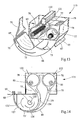
- Fig. 7 shows a further embodiment of an inventive Separating device.
- one roller 60 is provided in this exemplary embodiment.
- Air nozzles 73 as shown in Fig. 7 can be used. These have to not only be arranged on the chamber surface, but can be in the separation chamber 61 can also be distributed.
- the air currents carry the Fibers of the roller 60 too. Instead of one roller, several can be used Rollers are used.
- the function of the roller 60 or more Rollers 60 corresponds to the function of Fig. 6.
- By the air currents 74 there is increased turbulence in the separation chamber 61, so that the separation of the fibers compared to the embodiment 6 is improved.
- the separated fibers 65 arrive correspondingly through the screen 64 as in the example according to FIG. 6.
- the air flow is thereby the negative pressure applied at the end of the fleece 69 and that from the Nozzle ledge 67 flowing air flow 68 generated. It can too several nozzle strips are used.
- the main air flow begins above the sieve 64, passes the stirrer rows 82 and 83 as well as that Sieve 64. The main air flow then reaches the fluidized bed area 66 and passes through the fluidized bed 66 to the end.
- the essentially non-isolated fiber material or fiber / fiber group mixture 31 reaches the housing above the screen 64. Instead of the illustration in FIG. 8, this can also be inclined at an angle be like with 45 ° to the horizontal.
- the fiber / fiber group mixture 31 comes under the influence of gravity and under the influence of Main air flow in the area of stirring tools 82 and 83.
- Die Stirrer rows 82 and 83 consist of one behind the other Stirring rods that drive a suitable stirring tool.
- the Mixing tools are offset by 90 ° to each other. It can too other displacement angles can be provided.
- the uncommon Fiber groups are torn apart by the rotating stirring tools, accelerated and hit against the screen 64 of the housing. Instead of of the screen 64 can also be a perforated plate or a round bar grid Find use.
- the fiber groups or the fiber group mixture 31 is thrown against the sieve 64 until it is in Have dissolved individual fibers and passed the sieve 64 in the main air flow to have. Then the fibers arrive as in the previous ones Embodiments on the fluidized bed 66 and one Suction belt conveyor, which is also not shown in Fig. 8.
- the in Fig. 8 shown separating device is at least with respect to Stirrer series 82 and 83 from EP 0 616 056 B1 from M + J Fibretech A / S, Denmark, known.
- the disclosure content of EP 0 616 056 B1 is intended be fully included in this patent application.
- Separating device 115 is in a schematic in FIG. 9 three-dimensional representation disclosed. That essentially uncommon fiber material or fiber / fiber group mixture transported through the air streams 76 into the sieve drums 78. This happens via lateral openings 77 in the housing 79. The fiber material is in Blown in direction of the longitudinal axes of the sieve drums 78. By the blowing the fiber material on both sides counterclockwise results there is a circumferential ring flow 80. The ring flow is superimposed 80 of a flow normal or substantially perpendicular to it, the by a vacuum applied to the fleece bed end 69 and a Airflow 68 is caused.
- Negative pressure arises from the negative pressure in a not shown Suction belt conveyor, which is arranged at the fluid bed end 69 and for another on the air flow 72, which is conveyed through the suction nozzle 71 becomes.
- the normal flow takes its place above the sieve drums 78 Beginning and passes the screening drums 78 through their jacket openings.
- the Normal flow then reaches the fluidized bed area 66 and passes through it the same to the end 69, where part of the normal flow at the wedge 70 is separated from the fibers.
- the non-isolated fiber material arrives in the drums 78 Inner circumferential surfaces of the drums 78.
- the drums 78 rotate with one Direction of rotation 81 of the sieve drums 78 in the clockwise direction. That on the Drum jacket surfaces stored, essentially uncontaminated
- the rotating drum drums the fiber material Separation rollers 85 fed.
- the separating rollers 85 rotate in Direction of rotation 84 of the separating rollers 85 against the Clockwise. Alternatively, it would be clockwise rotation possible.
- the separating rollers 85 or needle rollers capture the unsingle fiber groups and tear them apart as well as accelerate them this.
- the fiber groups are against the inner surface of the Drums 78 flung until they dissolved into individual fibers and have passed the jacket openings, i.e. from the air flow (the Normal flow) detected and passed through the sieve drum 78 or be sucked.
- a drum can also be used be provided with perforated sheets or round bar grids.
- the fibers or individual fibers are caught by an air stream and sucked through the radial openings of the drum.
- the air flow causes the fibers to become a fluid bed promoted.
- the fiber-laden flow reaches the fluid bed is deflected and guided along the curved fluid bed. Due to the centrifugal forces acting on the fibers, they move Fibers to the curved guide wall and flow to the suction belt conveyor.
- the air flowing above the fibers becomes on the wedge or separator 70 separated and discharged via the suction nozzle 71.
- the corresponding fiber streams 75 are shown schematically in FIG. 9. There are isolated fibers from one of the nozzle strips 67 escaping air flow 68 is detected and corresponding to that Fluid bed end 69 fed, just like that on the fluid bed 66 individual fibers coming through the air flow 68. It can several nozzle strips can also be provided.
- Fiber groups that pass through the Drums 78 that have not or have not been completely separated come with the ring flow 80 into the parallel drum 78.
- the fibers pass through the openings 132 of the sieve drums 78. Im only isolated fibers can essentially pass through the openings 132 to step.
- the openings 132 are thus designed such that only individual fibers can pass through.
- the separating device shown in FIG. 9 corresponds at least to partly those of WU 01/54873 A1 or US 4,640,810 A from Scanweb, Denmark or USA.
- the revelation the just mentioned patent application or the just mentioned US patent is to be fully included in the disclosure content of this Patent application to be included.
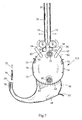
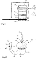
- FIG. 10 shows a schematic representation of a Strand making machine 110.
- FIG. 11 shows part of the strand making machine 110 in one Top view in the direction of arrow A and Fig. 12 is a side view of the 10 in the direction of arrow B.
- the uncontaminated fiber material arrives at the chute 32 Dosing device 34, which in this example has a pair of feed rollers 34 a rotating roller 32.
- the direction of material entry 100 is in Fig. 11 in the plane of the drawing down, as is shown schematically there.
- the non-separated fiber material is in the separation chamber 61 sporadically.
- the by the air flow in the suction nozzle 71 and the Air flow 72 ′ in the suction belt conveyor 89 generates air flow on the fluidized bed 66 promotes the individual fibers 65.
- the air flow 72 in the suction nozzle 71 is upward from the plane of the drawing with respect to their direction in Fig. 11 out as shown in Fig. 11. Airflow 72 also transports excess fibers.
- the separated fibers 65 move on the fluidized bed 66 in the direction of Fluid bed end 69, at which, as shown in the figures Suction belt conveyor 89 is arranged.
- the suction belt conveyor 89 prevails through continuous air suction vacuum. This air suction is represented schematically by the air flow 72 '. The vacuum sucks the isolated fibers 65 and holds them on the air-permeable suction belt Suction belt conveyor 89 fixed.
- the separated fibers 65 are corresponding to the air-permeable Suction belt of the suction belt conveyor 89 showered.
- the suction belt 116 moves in the direction of the strand production machine 110, that is to say in FIG. 10 to the left.
- a thickness is formed linearly towards the strand machine 110 increasing fiber cake or fiber stream 86 on the suction belt.
- the heaped fiber stream 86 is of different strengths and will end the fill-up zone of the suction belt conveyor 89 by means of trimming by a Trimmer 88 trimmed to a uniform thickness.
- the Trimming device 88 may be a mechanical one such as Trimmer disks or a pneumatic one, for example using air nozzles.
- the Mechanical trimming is inherent in cigarette rod machines known.
- Pneumatic trimming is done in such a way that it is horizontal at the end of the fiber stream 86 a nozzle is arranged from which a Air jet emerges and pulls out part of the fiber stream 86 so that Excess fibers 87 are removed. It can be a point jet nozzle or use a flat jet nozzle.
- the fiber stream 86 is divided into a trimmed one Fiber strand 90 and a strand of excess fibers 87. It is too possible, all fibers below a trim size of one Detect the jet and tear it away. The excess fibers are returned to the fiber processing process and will later again formed into a fiber strand.
- the trimmed fiber strand 90 is held on the suction belt 116 and in Moved towards the strand machine 110. With the trimmed fiber strand 90 it is a loose nonwoven fabric, which by a Compression band 92 is compressed. Instead of the compression band 92 a role can also be used. You can also have several Tapes or rolls are used. There is also a side Densification of the fiber cake, as shown in particular by Fig. 11 is. In Fig. 11, the compression bands 101 are shown that are conical run to each other at the speed of the suction belt with the Fiber cake. Create the toothed shape of the compression bands 101 Zones of different densities in the compressed fiber cake. In the zones The filter strand is cut later with a higher density.
- the trimmed and compressed fiber strand 91 is fed to the strand machine 110 passed.
- the transfer takes place by releasing the compacted Fiber strand 91 from suction belt 116 and the application of fiber strand 91 on a format tape of the strand machine 110.
- the format tape is in the Figures not shown. This can be a standard format tape act that also with a normal filter rod machine or Cigarette rod machine is used.
- the handover is from a nozzle 93 directed from above onto the compressed fiber strand 91 carried by an air flow 94.
- a fiber filter strand 95 is produced in the strand machine 110, whereby from a bobbin 98 a wrapping material strip 99 around the fiber material is wrapped as usual. Through volume reduction and round shaping or oval shaping of the compressed fiber strand 91 when enveloping with A certain internal pressure builds up in the wrapping material strip 99 Fiber filter strand 95 on.
- Binding components contained in the fiber mixture superficial heated and melted. Accordingly, the outer Layers of bicomponent fibers are melted so that a Connection between the fibers is created. This is particularly true of referred to the applicant's patent application DE 102 17 410.5.
- the Hardener 96 can also be a microwave heater, a Include laser heating, heating plates or sliding contacts.
- the binding components By Heating the binding components combines the individual fibers in the Fiber strand with each other and merge superficially. When cooling down the melted areas of the fiber strand harden again. The The resulting lattice structure gives the fiber strand stability and hardness. Finally, the hardened fiber filter strand 95 is turned into fiber filter rods 97 cut. The hardening of the fiber filter is also after Cutting into the fiber filter rods 97 possible.
- the air flow 102 still shown in FIG. 12 serves as the air flows previous embodiments also for the transport of the fiber material.
- FIG. 13 is a three-dimensional schematic representation of a fifth Embodiment of the separating device according to the invention shown, which is similar to that of FIG. 9.
- a granulate metering device 120 provided.
- the granulate metering device 120 scatters over the entire width of the separating device 115 a granulate between the sieve drums 78 into the separating device 115 Granules 121 mix in the area of the sieve drums 78 with the the fibers emerging from the sieve drums 78.
- a mixture is created isolated fibers and granules, which in the air flow on the fluidized bed to Suction line conveyor, which is behind the suction line end 79 in the conveying direction is arranged, is promoted.
- FIG. 14 shows a schematic cross-sectional illustration of another Separating device 115 according to the invention.
- the airflow is improved, so that more uniform Fiber streams 75 and 75 'are generated.
- An air stream 122 enters the upper area of the sieve drum 78 into the device.
- the from the Sieve drums 78 emerging individual fibers enter channels 123 and 124 and are down by the appropriate airflow led into the area of the fluidized bed 66.
- the fiber streams 75 are combined into a fiber stream 75 '.
- a large part of the transport air is from the fiber stream separated, which is represented by the air flow 122 '.
- the Fiber stream 75 comes in after the union of the two fiber streams 75 a channel formed by the fluidized bed 66 and the separator 127 becomes. At this point, depending on the procedure, it may be possible that a fleece has already formed or it may also be that the fibers are still isolated.
- the fiber stream 75 ' is then through the negative pressure applied to the suction belt conveyor 89 to the fluid bed end 69 and the suction belt conveyor 89 transported.
- FIG 15 shows a corresponding schematic sectional illustration, the 14 is similar to that of FIG.
- a granule metering device 120 above the screening drums 78 arranged.
- Two extraction nozzles become the respective Sieve drums 78 granules 121 fed.
- FIG. 16 shows a further embodiment according to the invention Separating device 115.
- the addition of granules 121 from the granule metering device 120 is near the fluidized bed end 69 carried out.
- Granules 121 reach an acceleration element 129, which can be a roller, a brush or a nozzle. That accelerated Granules 121 reach the fluidized bed through line 130, specifically into a vertical fluidized bed section 131.
Landscapes
- Cigarettes, Filters, And Manufacturing Of Filters (AREA)
- Nonwoven Fabrics (AREA)
- Glass Compositions (AREA)
- Manufacturing Of Cigar And Cigarette Tobacco (AREA)
Abstract
Description
Die Erfindung betrifft ein Verfahren zur Aufbereitung endlicher Fasern zur Verwendung bei der Herstellung von Filtern der tabakverarbeitenden Industrie. Die Erfindung betrifft ferner eine Aufbereitungseinrichtung für endliche Fasern zur Verwendung bei der Herstellung von Filtern der tabakverarbeitenden Industrie, umfassend wenigstens eine Vorrichtung zum Vereinzeln der endlichen Fasern, und wenigstens eine Dosiervorrichtung, wobei wenigstens ein Mittel zum Transportieren der endlichen Fasern von der wenigstens einen Dosiervorrichtung zur wenigstens einen Vorrichtung zum Vereinzeln vorgesehen ist.The invention relates to a method for processing finite fibers for Use in the manufacture of filters for tobacco processing Industry. The invention further relates to a processing device for finite fibers for use in the manufacture of filters tobacco processing industry, comprising at least one device for separating the finite fibers, and at least one Dosing device, wherein at least one means for transporting the finite fibers from the at least one metering device to the at least one device for separating is provided.
Ein Verfahren zur Aufbereitung von Filtermaterialien und eine entsprechende Einrichtung zur Aufbereitung von Filtermaterialien zur Herstellung von Filtern der tabakverarbeitenden Industrie ist aus der GB 718 332 bekannt. Hierbei werden mittels einer Tabakschneidemaschine Schnipsel eines Materials hergestellt und diese einer Strangmaschine, ähnlich einer Zigarettenstrangmaschine, zugeführt, wobei die Schnipsel mit einem chemischen Mittel imprägniert werden, um einen ungewünschten Geschmack zu verhindern und zu verhindern, daß die Schnipsel aus den Endstücken der entsprechend hergestellten Filter herausfallen. Die geschnittenen Schnipsel werden mittels einer Trommel in den Wirkbereich einer Stachelwalze gefördert und mittels der Stachelwalze von der Trommel auf ein Förderband gefördert, um anschließend einer weiteren Fördertrommel zugeführt zu werden, aus der die Schnipsel mittels einer weiteren Stachel- bzw. Schlägerwalze ausgeschlagen werden und einem Format zugeführt werden, in dem der Filterstrang mit einem Umhüllungsstreifen gebildet wird. Die Schnipsel aus Materialien wie Papier, Cellulose, Textilien, synthetische Materialien oder ähnlichem, haben eine ähnliche Struktur wie geschnittener Tabak.A process for the preparation of filter materials and a appropriate device for the preparation of filter materials for Manufacture of filters for the tobacco processing industry is from the UK 718 332 known. Here, using a tobacco cutting machine Snippets of a material produced and this a strand machine, similar to a cigarette rod machine, with the snippets be impregnated with a chemical agent to make an unwanted one To prevent taste and prevent the snippets from coming out End pieces of the correspondingly manufactured filters fall out. The cut snippets are in the knitting area by means of a drum promoted a spiked roller and by means of the spiked roller of the Conveyed drum on a conveyor belt, then another To be fed conveyor drum, from which the snippets by means of a another spiked or beater roller are knocked out and one Format are supplied in which the filter strand with a Wrapping strip is formed. The snippets of materials like paper, Cellulose, textiles, synthetic materials or the like have one structure similar to cut tobacco.
Aufgrund der Form der Schnipsel ist es nur schwer möglich, Filter mit homogenen Eigenschaften herzustellen. Außerdem ist die Variabilität der Einstellung der Filtereigenschaften nur sehr bedingt möglich.Due to the shape of the snippet, it is difficult to use filters to produce homogeneous properties. In addition, the variability of the Setting the filter properties is only possible to a very limited extent.
Demgegenüber ist es Aufgabe der vorliegenden Erfindung, ein Verfahren zur Aufbereitung von Filtermaterial und eine Aufbereitungseinrichtung für Filtermaterial zur Verwendung bei der Herstellung von Filtern der tabakverarbeitenden Industrie anzugeben, mittels der sehr homogene Filter herstellbar sind und die eine hohe Variabilität der Eigenschaften des herzustellenden Filters ermöglichen.In contrast, the object of the present invention is a method for the treatment of filter material and a treatment device for Filter material for use in the manufacture of filters specify tobacco processing industry, by means of the very homogeneous filter are producible and the high variability of the properties of the enable filters to be manufactured.
Gelöst wird diese Aufgabe durch ein Verfahren zur Aufbereitung von Filtermaterial zur Verwendung bei der Herstellung von Filtern der tabakverarbeitenden Industrie mit den folgenden Verfahrensschritten:
- Zuführen endlicher Fasern zu einer Vereinzelungsvorrichtung,
- Vereinzeln der Fasern und
- Transportieren der vereinzelten Fasern in Richtung einer Strangaufbauvorrichtung.
- Feeding finite fibers to a separating device,
- Separating the fibers and
- Transporting the separated fibers in the direction of a strand building device.
Durch Verwendung von endlichen Fasern als Filtermaterial und durch ein im wesentlichen vollständiges Vereinzeln dieser Fasern vor dem Bilden des Stranges, aus dem im folgenden der Filter gebildet wird, ist es möglich, sehr homogene Filtereigenschaften zu erzielen. Hierbei ist gerade das im wesentlichen vollständige Vereinzeln der Fasern von immanenter Wichtigkeit, da nur vereinzelte Fasern, die anschließend wieder zu einem Vlies aus den vereinzelten Fasern umgebildet werden, es ermöglichen, ein Vlies mit gleichmäßiger und homogener Dichte herzustellen.By using finite fibers as filter material and by a essentially completely separating these fibers before forming the Strand, from which the filter is subsequently formed, it is possible to achieve very homogeneous filter properties. This is exactly what essential complete separation of the fibers of immanent Importance, since only isolated fibers, which subsequently become one Fleece can be reshaped from the individual fibers, making it possible to To produce fleece with a uniform and homogeneous density.
Das Erscheinungsbild eines Stromes aus vereinzelten Fasern ähnelt dem eines Schneesturmes, also einem Strom von Fasern, der eine homogene statistische Verteilung der Fasern sowohl räumlich als auch zeitlich aufweist. Insbesondere bedeutet das vollständige Vereinzeln der Fasern, daß im wesentlichen keine Gruppen von Fasern, die miteinander verbunden sind, mehr vorhanden sind. Erst nach dem Vereinzeln der Fasern wird wieder ein Verbund der Fasern bspw. eine vliesartige Struktur hergestellt. Durch Auflösung der Fasergruppen, durch Vereinzelung der Fasern in Einzelfasern, kann anschließend ein Vlies hergestellt werden, der keine Brücken und Hohlräume enthält.The appearance of a stream of isolated fibers is similar to that a snowstorm, a stream of fibers that is homogeneous statistical distribution of the fibers both spatially and temporally having. In particular, the complete separation of the fibers means that essentially no groups of fibers that are together are connected, there are more. Only after separating the Fibers again become a composite of the fibers, for example a fleece-like structure manufactured. By dissolving the fiber groups, by separating the Fibers in single fibers, a nonwoven can then be made contains no bridges and cavities.
Wenn das Transportieren der vereinzelten Fasern wenigstens teilweise mittels eines Luftstromes geschieht, können die vereinzelten Fasern, ohne Fasergruppen zu bilden, transportiert werden. Eine besonders bevorzugte Ausführungsform des erfindungsgemäßen Verfahrens liegt dann vor, wenn das Vereinzeln der Fasern wenigstens teilweise mittels eines Luftstroms geschieht. Hierdurch wird der Vereinzelungsgrad sehr hoch. Es wird viel Luft verwendet, um die Fasern zu vereinzeln. Im Fließbettbereich wird dann überschüssige Luft von dem Faserstrom wenigstens teilweise abgeschieden. When transporting the separated fibers at least partially happens by means of an air flow, the separated fibers without Form fiber groups to be transported. A particularly preferred one Embodiment of the method according to the invention is present when separating the fibers at least partially by means of an air stream happens. This makes the degree of separation very high. It will be a lot Air is used to separate the fibers. Then in the fluidized bed area excess air from the fiber stream at least partially deposited.
Wenn das Vereinzeln der Fasern wenigstens teilweise mittels eines Hindurchtretens durch Öffnungen eines mit einer Mehrzahl von Öffnungen versehenen Vorrichtung geschieht, ist ein hoher Wirkungsgrad bei der Vereinzelung möglich. Wenn das Zuführen der Fasern wenigstens teilweise mittels eines Luftstromes geschieht, verbleiben vorvereinzelte Fasern beim Zuführen im wesentlichen vereinzelt. Vorzugsweise werden die vereinzelten Fasern und auch die Fasergruppen, die vorm (im wesentlichen vollständigen) Vereinzeln der Fasern aufbereitet werden, im wesentlichen nur mit Transportluft bzw. einem Luftstrom zugeführt.If the separation of the fibers at least partially by means of a Passing through openings one with a plurality of openings provided device is a high efficiency in the Separation possible. When feeding the fibers at least partially happens by means of an air flow, pre-separated fibers remain with Feeding essentially isolated. Preferably the scattered fibers and also the fiber groups that vorm (essentially complete) separating the fibers are processed, essentially only supplied with transport air or an air flow.
Wenn wenigstens zwei Vereinzelungsschritte vorgesehen sind, wird ein höherer Grad der Vereinzelung der Fasern erreicht. Vorzugsweise geschieht eine Vorvereinzelung von in einem Verbund vorliegenden endlichen Fasern. Hierzu wird vorzugsweise eine Hammermühle oder ein Ballenauflöser verwendet. Eine Hammermühle findet dann Anwendung, wenn ein Faserfilz zur Verfügung gestellt wird. Ein Ballenauflöser findet dann Anwendung, wenn ein Faserballen zur Verfügung gestellt wird.If at least two separation steps are provided, one becomes higher degree of fiber separation. Preferably there is a pre-separation of existing in a network finite fibers. For this purpose, a hammer mill or a Bale breaker used. A hammer mill is then used, if a fiber felt is provided. A bale breaker finds Use when a fiber bale is made available.
In einer bevorzugten Weiterbildung des erfindungsgemäßen Verfahrens ist wenigstens ein Dosierungsschritt vorgesehen, mittels dem die Menge der Fasern, insbesondere vorgebbar, dosiert wird. Es kann hierbei eine Vordosierung und/oder eine Hauptdosierung vorgesehen sein. Mittels der Vordosierung wird grob der Durchsatz der aufzubereitenden Fasern eingestellt. Mittels der Hauptdosierung wird eine feinere Einstellung ermöglicht.In a preferred development of the method according to the invention at least one dosing step is provided, by means of which the amount of Fibers, in particular predeterminable, is metered. There can be one Predosing and / or a main dosing may be provided. By means of the The throughput of the fibers to be processed becomes rough set. By means of the main dosage, a finer setting is achieved allows.
Wenn wenigstens ein Dosierungsschritt gleichzeitig mit einem Vereinzelungsschritt geschieht, ist eine besonders effektive und schnelle Verfahrensführung möglich.If at least one dosing step coincides with one Separation step happens to be a particularly effective and quick Procedure management possible.
Vorzugsweise finden verschiedene Fasersorten Verwendung, so daß Filter
mit den verschiedensten Filtereigenschaften herstellbar sind. Als
Fasermaterialien kommen bspw. Celluloseacetat, Cellulose, Kohlefasern
und Mehrfachkomponentenfasern, insbesondere Bikomponentenfasern in
Frage. Bezüglich der in Frage kommenden Komponenten wird
insbesondere Bezug genommen auf die DE 102 17 410.5 der Anmelderin.Different types of fibers are preferably used, so that filters
can be produced with a wide variety of filter properties. As
Fiber materials come, for example, cellulose acetate, cellulose, carbon fibers
and multi-component fibers, in particular bicomponent fibers in
Question. Regarding the components in question
in particular reference to the applicant's
Vorzugsweise werden die verschiedenen Fasersorten gemischt. Es ist ferner möglich, wenigstens ein Additiv hinzuzufügen. Bei dem Additiv handelt es sich bspw. um ein Bindemittel wie Latex oder um Granulatmaterial, das besonders effektiv Bestandteile des Zigarettenrauches bindet wie bspw. Kohleaktivgranulat.The different types of fibers are preferably mixed. It is also possible to add at least one additive. With the additive is it, for example, a binder such as latex or Granulate material that is particularly effective components of the Cigarette smoke binds like, for example, coal granules.
In einer besonders bevorzugten Ausführungsform des erfindungsgemäßen
Verfahrens geschieht eine vollständige Vereinzelung mit oder im Anschluß
an einen zweiten oder dritten Dosierungsschritt, wobei diese nach einem
dritten Dosierungsschritt insbesondere beim Vorsehen einer Vordosierung
ermöglicht ist. Besonders bevorzugt ist es, wenn die Faserlänge kleiner ist
als die Länge des herzustellen Filters. Bezüglich der Faserlänge wird auch
vollumfänglich auf die DE 102 17 410.5 der Anmelderin verwiesen, die in
den Offenbarungsgehalt dieser Anmeldung aufgenommen sein soll. Die
Länge der Fasern soll demnach zwischen 0,1 mm und 30 mm und
insbesondere zwischen 0,2 mm und 10 mm liegen. Bei der Länge des
herzustellenden Filters handelt es sich um einen üblichen Filter für eine
Zigarette bzw. ein Filtersegment beim Multisegmentfiltern von Zigaretten.
Wenn außerdem der mittlere Faserdurchmesser im Bereich von 10 bis 40
µm, insbesondere 20 bis 38 µm liegt und besonders bevorzugt zwischen 30
und 35 µm, ist ein sehr homogener Filter nach der erfindungsgemäßen
Aufbereitung herstellbar.In a particularly preferred embodiment of the invention
The procedure is completely separated with or afterwards
to a second or third dosing step, after a
third dosing step, especially when providing a pre-dosing
is possible. It is particularly preferred if the fiber length is shorter
than the length of the filter to manufacture. Regarding the fiber length, too
fully referred to the applicant's
Vorzugsweise ist ein Verfahren zur Herstellung von Filtern der tabakverarbeitenden Industrie, umfassend ein erfindungsgemäßes Verfahren zur Aufbereitung von Filtermaterial der vorstehend beschriebenen Art dadurch vorgesehen, daß außerdem anschließend ein Faserstrang gebildet wird und der Strang in Filterstäbe zerteilt wird.A method for producing filters is preferably the tobacco processing industry, comprising an inventive Process for the preparation of filter material of the above described type provided that in addition subsequently Fiber strand is formed and the strand is divided into filter rods.
Vorzugsweise wird bei dem Verfahren zur Herstellung von Filtern der tabakverarbeitenden Industrie spätestens beim Strangaufbau ein Vlies aus den vereinzelten endlichen Fasern gebildet. Zum Strangaufbau aus endlichen Fasern werden diesen über ein Fließ transportiert und einem Saugbandförderer zugeführt. Hierdurch bildet sich ein Vlies auf der Oberfläche des Saugbandförderers. Der Saugbandförderer ist speziell ausgebildet, um die endlichen Fasern, die bspw. einen relativ kleinen Durchmesser haben, auf dem Saugband zu halten. Der Strangaufbau entspricht an sich im wesentlichen dem Strangaufbau eines Tabakstrangs, wobei allerdings entsprechende Maßnahmen bzw. Variationen eingeführt werden, um das von der Größe und Struktur her andere Material der endlichen Fasern im Vergleich zu Tabakfasern in einen homogenen Strang zu überführen. Hierzu wird insbesondere Bezug genommen auf die am selben Tage eingereichte europäische Patentanmeldung der Anmelderin mit dem Titel "Verfahren und Einrichtung zur Herstellung eines Filterstrangs".In the method for producing filters, the tobacco-processing industry at the latest when building a strand the isolated finite fibers. To build up from Finite fibers are transported over a flow and one Suction belt conveyor supplied. This creates a fleece on the Surface of the suction belt conveyor. The suction belt conveyor is special formed to the finite fibers, for example a relatively small Have diameters to hold on the suction belt. The strand construction essentially corresponds to the structure of a tobacco rod, however, appropriate measures or variations have been introduced in order to use the material of different sizes and structures finite fibers compared to tobacco fibers in a homogeneous strand to convict. In this regard, reference is made in particular to the on European patent application filed by the applicant on the same day entitled "Process and Equipment for the Production of a Filter rod ".
Die Erfindung wird ferner durch eine Aufbereitungseinrichtung für Filtermaterial zur Verwendung bei der Herstellung von Filtern der tabakverarbeitenden Industrie gelöst, die wenigstens eine Vorrichtung zum Vereinzeln des Filtermaterials und wenigstens eine Dosiervorrichtung umfaßt, wobei wenigstens ein Mittel zum Zuführen des Filtermaterials von der wenigstens einen Dosiervorrichtung zu der wenigstens einen Vorrichtung zum Vereinzeln vorgesehen ist, wobei die Aufbereitungseinrichtung dadurch weitergebildet ist, daß die Aufbereitungseinrichtung ausgestaltet ist, um das Filtermaterial, das endliche Fasern umfaßt, aufzubereiten und wobei die wenigstens eine Vorrichtung zum Vereinzeln der endlichen Fasern eine im wesentlichen vollständige Vereinzelung ermöglicht.The invention is further enhanced by a processing device for Filter material for use in the manufacture of filters tobacco processing industry solved the at least one device for Separating the filter material and at least one metering device comprising at least one means for feeding the filter material from the at least one dosing device to the at least one Device for separating is provided, the Processing device is further developed in that the Processing device is configured to the filter material comprises finite fibers, to prepare and wherein the at least one Device for separating the finite fibers essentially one complete separation possible.
Durch die erfindungsgemäße Aufbereitungseinrichtung ist ein aus dem entsprechend aufbereiteten Filtermaterial hergestellter Filter mit sehr homogenen Eigenschaften realisierbar.By means of the processing device according to the invention, one from the according to prepared filter material, filter with very homogeneous properties can be realized.
Vorzugsweise umfaßt das Mittel zum Zuführen einen Luftstrom, wodurch ein noch homogenerer Filter herstellbar ist. Preferably, the means for feeding comprises an air flow, thereby an even more homogeneous filter can be produced.
In einer besonders bevorzugten Ausführungsform der erfindungsgemäßen Aufbereitungseinrichtung ist zum Vereinzeln der Faser ein Luftstrom durch und/oder in der Vorrichtung erforderlich. Hierdurch wird der Vereinzelungsgrad sehr hoch. Wenn die Vorrichtung zum Vereinzeln eine Mehrzahl von Öffnungen umfasst, durch die die Fasern aus der Vorrichtung vereinzelt austreten können, ist eine besonders effektive Aufbereitungseinrichtung gegeben.In a particularly preferred embodiment of the invention Processing device is an air flow through to separate the fiber and / or required in the device. This will Degree of separation very high. If the device for separating a Includes a plurality of openings through which the fibers from the device Leaving sporadically is a particularly effective treatment facility given.
Eine besonders einfach zu realisierende Dosiervorrichtung umfaßt einen Fallschacht, aus dem eine rotierende Walze Fasern herausbefördert. Wenn im unteren Bereich der Dosiervorrichtung ein Paar Einzugswalzen vorgesehen ist, kann auf schonende Weise Filtermaterial dosiert werden.A particularly easy to implement metering device includes one Fall chute from which a rotating roller conveys fibers. If in the lower area of the metering device a pair of feed rollers provided, filter material can be dosed gently.
Eine besonders gute und homogene Vereinzelung ist dann gegeben, wenn
die Vorrichtung zum Vereinzeln durch Zusammenwirken wenigstens eines
sich drehenden Elements, wenigstens eines mit Durchlässen versehenen
Elements und einem Luftstrom eine Vereinzelung der Fasern ermöglicht.
Vorzugsweise hat die Dosiervorrichtung bzw. die wenigstens eine
Dosiervorrichtung zusätzlich eine Vereinzelungsfunktion, wodurch der
Vereinzelungsgrad der gesamten Aufbereitungseinrichtung weiter
vergrößert werden kann. Wenn vorzugsweise eine Mischvorrichtung
vorgesehen ist, ist es möglich, verschiedene Materialien und auch
verschiedene Fasern aufzubereiten. Bei den Fasern kann es sich um
Cellulosefasern, Fasern aus thermoplastischer Stärke, Flachsfasern,
Hanffasern, Leinfasern, Schafwollfasern und Baumwollfasern bzw., wie
oben schon dargestellt, Mehrfachkomponentenfasern, handeln.
Vorzugsweise ermöglicht die Mischvorrichtung zusätzlich eine
Vereinzelung und/oder Dosierung der Fasern. In diesem Fall ist eine sehr
kompakt bauende Aufbereitungseinrichtung möglich. In einer besonders
bevorzugten Ausführungsform der Erfindung ist die
Aufbereitungseinrichtung derart ausgebildet, daß endliche Fasern mit einer
Länge, die kleiner als die eines herzustellenden Filters ist, aufzubereiten.
Ferner vorzugsweise ist die Aufbereitungseinrichtung derart ausgestaltet,
um endliche Fasern mit einem mittleren Faserdurchmesser im Bereich von
10 bis 40 µm, insbesondere 20 bis 38 µm aufzubereiten. Ein besonders
bevorzugter Faserdurchmesser liegt in einem Bereich von 30 bis 35 µm.A particularly good and homogeneous separation is given if
the device for separating by interaction of at least one
rotating element, at least one provided with passages
Elements and an air flow allows the fibers to be separated.
The metering device or the at least one preferably has
Dosing device additionally a separating function, whereby the
The degree of separation of the entire processing facility continues
can be enlarged. If preferably a mixing device
provided, it is possible to use different materials and also
to prepare different fibers. The fibers can be
Cellulose fibers, fibers made of thermoplastic starch, flax fibers,
Hemp fibers, flax fibers, sheep wool fibers and cotton fibers or, as
Already described above, multi-component fibers, act.
Preferably, the mixing device additionally enables one
Separation and / or dosing of the fibers. In this case it is a very
compact processing device possible. In one particularly
preferred embodiment of the invention is the
Processing device designed such that finite fibers with a
Length that is smaller than that of a filter to be manufactured.
Furthermore, the processing device is preferably designed such that
around finite fibers with an average fiber diameter in the range of
Erfindungsgemäß umfaßt eine Filterherstelleinrichtung eine erfindungsgemäße Aufbereitungseinrichtung, die vorstehend beschrieben wurde.According to the invention, a filter manufacturing device comprises a Processing device according to the invention, described above has been.
Ein erfindungsgemäßer Filter wird nach einem der vorstehend beschriebenen Verfahren hergestellt.An inventive filter is according to one of the above described method produced.
Im folgenden wird die Erfindung unter Bezugnahme auf die Zeichnungen, auf die im übrigen bezüglich aller im Text nicht näher erläuterten erfindungsgemäßen Einzelheiten ausdrücklich verwiesen wird, beschrieben. Es zeigen:
- Fig. 1
- eine schematische Darstellung des Verfahrensablaufs zur Aufbereitung von Filtermaterial,
- Fig. 2
- eine schematische Darstellung einer Vorrichtung zur Faservorbereitung,
- Fig. 3
- eine schematische Darstellung einer Vorrichtung zur Vordosierung,
- Fig. 4
- eine schematische Darstellung einer Vorrichtung zur Hauptdosierung,
- Fig. 5
- eine schematische Darstellung einer Mischtrommel,
- Fig. 6
- eine schematische Darstellung einer Dosiervorrichtung mit einer Vereinzelungsvorrichtung in einer ersten Ausführungsform,
- Fig. 7
- eine schematische Darstellung einer Hauptdosiervorrichtung mit einer Vereinzelungsvorrichtung in einer zweiten Ausführungsform,
- Fig. 8
- eine schematische Darstellung einer Vereinzelungsvorrichtung in einer dritten Ausführungsform,
- Fig. 9
- eine dreidimensionale schematische Darstellung einer Vereinzelungsvorrichtung in einer vierten Ausführungsform,
- Fig. 10
- eine schematische Ansicht einer Vorrichtung zur Filterstrangherstellung,
- Fig. 11
- einen Teil der Fig. 10 in einer Aufsicht in Richtung A, und
- Fig. 12
- einen Teil der Fig. 10 in schematischer Darstellung in Seitenansicht, in Richtung B,
- Fig.13
- eine schematische dreidimensionale Ansicht einer Vereinzelungsvorrichtung in einer fünften Ausführungsform,
- Fig. 14
- eine schematische Querschnittsdarstellung durch eine weitere erfinderische Ausführungsform einer Vereinzelungsvorrichtung,
- Fig. 15
- eine entsprechende schematische Darstellung wie in Fig. 14, wobei die Zufuhr von Granulat zusätzlich dargestellt ist, und
- Fig. 16
- eine schematische Darstellung entsprechend der Fig. 15, wobei die Granulatzufuhr in einem anderen Bereich vorgenommen wird.
- Fig. 1
- 1 shows a schematic representation of the process sequence for the preparation of filter material,
- Fig. 2
- 1 shows a schematic representation of a device for fiber preparation,
- Fig. 3
- 1 shows a schematic representation of a device for predosing,
- Fig. 4
- 1 shows a schematic representation of a device for main dosing,
- Fig. 5
- a schematic representation of a mixing drum,
- Fig. 6
- 1 shows a schematic illustration of a metering device with a separating device in a first embodiment,
- Fig. 7
- 1 shows a schematic representation of a main metering device with a separating device in a second embodiment,
- Fig. 8
- 1 shows a schematic illustration of a separating device in a third embodiment,
- Fig. 9
- 3 shows a three-dimensional schematic illustration of a separating device in a fourth embodiment,
- Fig. 10
- 1 shows a schematic view of a device for producing filter strands,
- Fig. 11
- a part of FIG. 10 in a plan in direction A, and
- Fig. 12
- 10 a part of FIG. 10 in a schematic illustration in a side view, in the direction B,
- Figure 13
- 2 shows a schematic three-dimensional view of a separating device in a fifth embodiment,
- Fig. 14
- 2 shows a schematic cross-sectional representation through a further inventive embodiment of a separating device,
- Fig. 15
- a corresponding schematic representation as in Fig. 14, wherein the supply of granules is also shown, and
- Fig. 16
- a schematic representation corresponding to FIG. 15, wherein the granulate feed is carried out in another area.
Fig. 1 zeigt eine schematische Darstellung eines Verfahrensablaufs von der
Aufbereitung bis zur Strangherstellung eines Filters der
tabakverarbeitenden Industrie. Durch die verschiedenen Wege der
Verfahrensführung ist die Verfahrensführung variabel möglich. In dem
Beispiel der Fig. 1 geschieht zunächst eine Faservorbereitung 1, bei der in
erster Linie die Überführung aller festgepreßten Lieferformen von
Faserstoffen in einen luftig-wolligen Zustand vorgenommen wird. Hierbei
sollen aufgelockerte Fasergruppen entstehen. Neben diesen Fasergruppen
können auch schon einzelne Fasern erzeugt werden. Die
Faservorbereitung 1 wird bspw. mit einer Vorrichtung gemäß Fig. 2
durchgeführt. Eine derartige Vorrichtung ist an sich bekannt. Zu den
festgepreßten Lieferformen gehören bspw. Faserballen und Fasermatten
(10) bzw. ein Faserfilz (10). Faserballen werden üblicherweise mittels
Ballenauflöser entpackt und Fasermatten (10) bzw. Faserfilz (10) mittels
einer Hammermühle 13.Fig. 1 shows a schematic representation of a process flow from the
Preparation up to the production of a filter
tobacco processing industry. Through the different ways of
The procedure is variable. By doing
Example of FIG. 1,
Auch unverpreßte Faserstoffe, die in einer dichten Packung vorliegen, werden in der Faservorbereitung aufgelockert und luftig, wollig aufgebauscht. Ein Ballenauflöser für Faserstoffe ist bspw. von der Firma Trützschler erwerbbar und eine Hammermühle für Faserstoffe bspw. von der Firma Kamas.Even uncompressed fibrous materials that are in a tight package, are loosened up in the fiber preparation and airy, woolly exaggerated. A bale breaker for fiber materials is from the company, for example Trützschler available and a hammer mill for fiber materials, for example from from the Kamas company.
Als zweiter Schritt, der optional in diesem Ausführungsbeispiel möglich ist,
geschieht eine Vordosierung 2. Eine Vordosierung 2 ist bspw. mit der
Vorrichtung gemäß Fig. 3 möglich. Das Vordosieren dient einer groben
Dosierung des Fasermaterials und einer weiteren Vereinzelung
dahingehend, daß die in Gruppen bzw. als dichte Packung vorliegenden
Fasern weiterhin aufgelockert werden. Auch an dieser Stelle können
weitere vollständig vereinzelte Fasern entstehen. Anstelle der Vordosierung
2 kann auch eine Hauptdosierung bzw. ein Dosieren 4 alleine durchgeführt
werden. Ob eine Vordosierung 2 notwendig ist, hängt von der
Beschaffenheit des der Faservorbereitung entstammenden Materials ab.
Das Ziel der Dosierung 4 bzw. der Vordosierung 2 ist die Realisierung
eines definierten stabilen gleichmäßigen Massenstromes von Fasern und
außerdem auch zum Teil schon eine Vorvereinzelung. Der Schritt des
Dosierens 4 führt zu einer weiteren Vereinzelung der Fasergruppen. Es ist
möglich, vor dem Schritt des Dosierens 4 einen Schritt des Mischens
und/oder Dosierens 3 vorzusehen. Bei diesem Schritt können mehrere
Filtermaterialien, wie in Fig. 1 durch die in das Kästchen 3 hineinführenden
Wege angedeutet ist, und ggf. ein Additiv wie ein Bindemittel
beispielsweise oder ein Aktivkohlegranulat gemischt werden.As a second step, which is optionally possible in this exemplary embodiment,
there is a
Es ist ferner möglich, das Verfahren in unterschiedlich aufgebauten bzw. gleich aufgebauten parallelen Aufbereitungs- und Dosierungsstrecken auszuführen, so daß mehrere verschiedene Faserstoffe parallel aufbereitet und dosiert werden können. Das Ziel des Mischens ist es, eine homogene Durchmischung der einzelnen Faserkomponenten und verschiedenen Zusätze zu erreichen. Ein Mischen und/oder Dosieren ist bspw. mit einer Vorrichtung gemäß der Fig. 5 möglich. Eine Hauptdosierung ist bspw. mit einer Vorrichtung gemäß Fig. 4 möglich.It is also possible to use differently constructed or identical preparation and dosing lines of the same design execute, so that several different fibers are processed in parallel and can be dosed. The goal of mixing is to get a homogeneous one Mixing of the individual fiber components and various To achieve additives. Mixing and / or dosing is, for example, with a 5 possible. A main dosage is, for example, with a device according to FIG. 4 possible.
Bei dem Schritt des Mischens und/oder Dosierens werden die
verschiedenen Fasermaterialien kontinuierlich oder diskontinuierlich
miteinander vermischt. Als Beispiel der Fig. 5 ist eine kontinuierliche
Mischvorrichtung 111 dargestellt. Die Mischvorrichtung 111 erfüllt auch
eine Pufferspeicherfunktion für die Faserstoffe. In dem Verfahrensschritt
des Mischens und/oder des Dosierens ist es nicht nur möglich,
verschiedene Fasern miteinander zu mischen, sondern auch Additive in
fester oder flüssiger Form beizumischen. Diese Additive dienen der
Bindung der Fasern aneinander und/oder beeinflussen die
Filtrationseigenschaften des Faserfilters günstig.In the mixing and / or dosing step, the
different fiber materials continuously or discontinuously
mixed together. 5 is a continuous
Der Austrag aus der Mischvorrichtung 111 erfolgt definiert, wodurch eine
Dosierfunktion gegeben ist. Insofern wäre es möglich, das Dosieren 4
durch ein Mischen und/oder Dosieren 5 zu umgehen. Nach dem Dosieren 4
oder dem Mischen und/oder Dosieren 5 wird das Fasermaterial einem
Schritt des Vereinzelns 6 zugeführt. Das Ziel der Vereinzelung ist eine
gänzliche Auflösung der verbliebenen Fasergruppen in Einzelfasern.
Dieses dient dazu, um im anschließenden Schritt des Strangherstellens 7
die einzelnen Fasern so neu zu gruppieren, daß eine optimale Vliesstruktur
entstehen kann, in der keine Brücken und Hohlräume enthalten sind.
Hierbei ist es wichtig, daß sich Faser für Faser aneinanderlegen kann und
so ein Vlies gebildet werden kann. Es ist somit gemäß Fig. 1 möglich, bis
zu drei Dosierschritte zu verwenden. Es können auch weitere
Dosierungsstufen der Vereinzelung vorgeschaltet sein.The discharge from the
Der aus der Vereinzelung austretende Faserstrom besteht aus einzelnen
Fasern, die in Luft bzw. in einem Luftstrom geführt werden. Das
Erscheinungsbild des Luftstromes mit den mitgeführten Fasern bzw. ein mit
Fasern beladener Luftstrom ist dem eines Schneesturmes sehr ähnlich.
Zum Strangherstellen werden die vereinzelten Fasern bspw. mit einem
Fließbett dem Saugband eines speziellen Saugbandförderers zugeführt.
Beim Strangherstellen 7 wird ein Strang mit konstantem Querschnitt
erzeugt, wobei der Querschnitt insbesondere konstant quadratisch ist,
wobei gleichzeitig eine gleichmäßige Dichte hergestellt wird. Spätestens
beim Strangaufbau liegen die Fasern in einer vliesartigen Struktur vor. Der
fertige Faserfilterstrang hat eine ausreichende Härte, Zugwiderstand,
Gewichtskonstanz, Retention und Weiterverarbeitbarkeit.The fiber stream emerging from the separation consists of individual
Fibers that are carried in air or in an air stream. The
Appearance of the air flow with the carried fibers or a with
Airflow loaded with fibers is very similar to that of a snowstorm.
For the production of the strand, the separated fibers are, for example, with a
Fluid bed fed to the suction belt of a special suction belt conveyor.
When producing
Fig. 2 zeigt eine Faservorbereitungsvorrichtung 114. Ein Faserfeld 10 wird
mittels Einzugswalzen 11 in den Wirkbereich einer Hammermühle 13 mit
Hämmern 12 gefördert. Die Hämmer 12 der Hammermühle 13 sind in
einem Gehäuse 14 untergebracht. Im Abreißbereich 15 schlagen die
Hämmer 12 auf den Faserfilz und bilden so Fasergruppen 16. Die
Fasergruppen 16 werden in einem Rohr 18 mittels Luftstrom 17
weitertransportiert. Es entsteht ein mit Fasergruppen beladener Luftstrom
19. An dieser Stelle können auch schon vereinzelte Fasern entstanden
sein. Die Hämmer 12 der Hammermühle 13 rotieren in Fallrichtung, so daß
die Fasern in Rotordrehrichtung tangential aus dem Gehäuse 14 der
Hammermühle 13 ausgeworfen werden.Fig. 2 shows a
In Fig. 3 ist schematisch eine Vordosiervorrichtung 113 dargestellt. Ein mit
Fasermaterial 41 beladener Luftstrom wird einem Abscheider 20 zugeführt,
der das Fasermaterial 41 von dem Luftstrom abscheidet, so daß
Fasermaterial 42 durch den Schacht 21 in den Speicherbehälter 22 fällt. Im
unteren Teil des Speicherbehälters 22 sind zwei Stachelwalzen 23
angeordnet. Die Stachelwalzen 23 rotieren langsam und führen das
Fasermaterial einer dritten Stachelwalze 24 zu. Die dritte Stachelwalze 24
rotiert schnell und reißt Fasergruppen aus dem Fasermaterial heraus.
Diese Fasergruppen gelangen in den Trichter 25, indem sie nach unten
rutschen. Am unteren Ende des Trichters 25 ist eine Zellradschleuse 26
angeordnet. Die Fasergruppen rutschen in die Zellen der Zellradschleuse
26 und werden in den Kanal 27 befördert. In dem Kanal 27 herrscht ein
Luftstrom 28, der die in den Kanal 27 abgegebenen Fasern bzw.
Fasergruppen mit sich nimmt. Der Luftstrom 28 nimmt auch schon aus dem
Verfahren zurückgeführte Fasern mit, die den Fasergruppen zugeführt
werden. Der Luftstrom 29 ist voll mit Fasern und Fasergruppen beladen.
Mit dem Luftstrom wird ein Fasern-/ Fasergruppen-Gemisch 29
transportiert. Durch eine Variation der Drehzahl der drehenden Teile,
nämlich Stachelwalzen 23 und 24 sowie der Zellradschleuse 26 kann der
Massendurchsatz eingestellt werden, so daß eine Vordosierung realisierbar
ist.A
Fig. 4 zeigt eine schematische Darstellung einer Dosiervorrichtung, mit der
eine Hauptdosierung ermöglicht ist. Das Fasern-/Fasergruppen-Gemisch
29 wird mittels eines Luftstromes in den Abscheider 30 z.B. eines
Rotationsabscheiders transportiert. Dort wird das Faser-/Fasergruppen-Gemisch
vom Luftstrom abgeschieden. Das abgeschiedene Fasermaterial
31 gelangt in den Stauschacht 32 und fällt in diesem nach unten zu den
Einzugswalzen 34. Es können auch mehrere Walzenpaare vorgesehen
sein oder ein Einzugsbänderpaar bzw. mehrere Einzugsbänderpaare. In
einem Abschnitt des Stauschachts 32 sind Vibrationselemente 33
vorgesehen, mittels der eine lückenlose Zufuhr des Fasern-/Fasergruppen-Gemisches
31 zu den Einzugswalzen 34 ermöglicht ist.Fig. 4 shows a schematic representation of a metering device with the
a main dosage is possible. The fiber /
Die Einzugswalzen 34 fördern das Fasermaterial zwischen die Abstreifer
35 in den durch diese gebildeten Dosierkanal 36. Eine rotierende Walze
37, bspw. eine Stachelwalze, reißt die Fasern aus dem Fasermaterial
heraus und trägt diese in den Kanal 38 ein. Im Kanal 38 herrscht eine
Luftströmung 39, die die Fasern bzw. das Fasermaterial 40 erfaßt und
entsprechend in Pfeilrichtung transportiert. Über die Drehzahl der
Einzugswalzen 34 wird der Massendurchsatz des Dosierkanals 36
vorgegeben.The
In Fig. 5 ist eine Mischvorrichtung 111 in schematischer, dreidimensionaler
Darstellung gezeigt. Verschiedene Fasermaterialien 43 und 44 sowie
weitere Fasermaterialien oder Additive 45 in flüssiger oder fester Phase
werden in den Mischraum 46 eingebracht. Bei den Fasermaterialien kann
es sich um Cellulosefasern, Fasern aus thermoplastischer Stärke,
Flachsfasern, Hanffasern, Leinfasern, Schafwollfasern, Baumwollfasern
oder Mehrfachkomponentenfasern, insbesondere Bikomponentenfasern
handeln, die eine Länge aufweisen, die kleiner ist als der herzustellende
Filter und eine Dicke aufweisen, die bspw. im Bereich von 25 und 30 µm
liegt. So sind bspw. Cellulosefasern stora fluff EF untreatet der Firma
StoraEnso Pulp AB verwendbar, die einen durchschnittlichen Querschnitt
von 30 µm aufweisen und eine Länge zwischen 0,4 und 7,2 mm. Als
Kunstfasern wie bspw. Bikomponentenfasern, können Fasern vom Typ
Trevira, 255 3,0 dtex HM mit einer Länge von 6 mm der Fa. Trevira GmbH
Verwendung finden. Diese haben einen Durchmesser von 25 µm. Als
weitere Beispiele von Kunstfasern können Celluloseacetatfasern,
Polypropylenfasern, Polyäthylenfasern und Polyäthylenterephthalatfasern
Verwendung finden. Als Additive können den Geschmack bzw. den Rauch
beeinflussende Materialien Verwendung finden wie Kohleaktivgranulat oder
Geschmacksstoffe und ferner Bindemittel, mittels der die Fasern
miteinander verklebt werden können.5, a
Das in den Mischraum 46 eingebrachte Fasermaterial 43 und 44 bzw. die
entsprechenden Additive 45 werden Walzen 50 - 52 zugeführt, die
während der Befüllung und des Mischvorganges mit geeigneten
Drehzahlen rotieren. Die Position der Walzen 50 - 52 ist vorzugsweise
sowohl horizontal als auch vertikal einstellbar. Damit sind die
Achsabstände der Walzen zueinander einstellbar. Es können auch mehrere
Walzen in verschiedenen Etagen angeordnet sein. Die zu mischenden
Komponenten werden von den Walzen 50 - 52 erfaßt, beschleunigt und im
Mischraum 46 durcheinandergewirbelt. Das Durcheinanderwirbeln bewirkt
eine Durchmischung der Komponenten. Die Verweildauer der zu
mischenden Komponenten im Mischraum 46 ist durch die geometrische
Beschaffenheit des Siebes 47 einstellbar. Außerdem ist die Verweildauer
der zu mischenden Komponenten im Mischraum 46 durch die Position
einer Schubblende, mittels der die Öffnungen des Siebes 47 teilweise oder
auch ganz geschlossen werden können, bestimmt. Die Schubblende ist in
der Figur nicht dargestellt.The
Das Fasergemisch 53 bzw. allgemein das Gemisch 53 wird durch die
Öffnungen des Siebes 47 in die Kammer 54 gefördert. Dieses kann
kontinuierlich oder in Intervallen erfolgen. Die Kammer 54 ist vorzugsweise
schwenkbar und wird von einem Luftstrom 55 durchströmt. Der Luftstrom
55 erfaßt das Gemisch 53 und reißt es mit sich. Der beladene Luftstrom 56
verläßt die Kammer 54 und führt das Gemisch 53 weiter.The
In Fig. 6 ist eine Vereinzelungsvorrichtung 115 in schematischer
Darstellung im Zusammenhang mit einer Dosiervorrichtung 112 dargestellt.
Die Dosiervorrichtung 112 entspricht im wesentlichen der Dosiervorrichtung
aus Fig. 4, wobei allerdings die Vibrationselemente 33 als getrennte
Abschnitte des Fallschachtes 32 dargestellt sind und die Abstreifer 35 eine
etwas andere Form als die in Fig. 4 aufweisen. Das durch die rotierende
Walze 37 aus dem Dosierkanal 36 herausgerissene Fasermaterial wird
direkt einer Vereinzelungskammer 61 zugeführt. Über die Drehzahl der
Einzugswalzen 34 wird der Massendurchsatz des Dosierkanals 36
bestimmt. Die gesamte Vereinzelungsvorrichtung wird von Luft
durchströmt. Diese Strömung 133 wird hervorgerufen durch den Unterdruck
am Fließbettende. Dieser Unterdruck entsteht zum einen durch die in dem
Absaugstutzen 71 geführte Luftströmung 72 und zum anderen durch die
Strömung im Saugbandförderer, der am Fließbettende 69 angeordnet ist
und in dieser Figur nicht dargestellt ist. 6 shows a
In der Vereinzelungskammer 61 bewegen sich die Fasern bzw. die
Fasergruppen unter Schwerkraft- und Strömungseinfluß durch die
Luftströmung 63 bzw. den Lufteintritt 63, der durch die
Ventilationsöffnungen 62 geschieht, in den Bereich der Walzen 60. Die
Walzen 60 der Reihe von Walzen 60 erfassen die unvereinzelten Fasern
(und natürlich auch schon teilweise vereinzelt vorliegende Fasern),
beschleunigen diese und schlagen sie gegen das Sieb 64 der
Vereinzelungskammer 61. Anstelle eines Siebes mit entsprechenden
Siebaustrittsflächen, können auch Lochbleche oder Rundstabgitter
Verwendung finden.The fibers or the move in the singling
Durch die mechanische Beanspruchung werden die Fasergruppen in
Einzelfasern aufgelöst und passieren schließlich das Sieb 64. Das heißt,
die Fasern werden nach ausreichender Vereinzelung von der durch das
Sieb führenden Strömung 133 erfasst und durch das Sieb 64 geführt bzw.
gesaugt. Die Drehzahl der Walzen 60 und die Fläche so wie die Stärke der
Strömung 133 bestimmen den Massendurchsatz der Vereinzelungskammer
61 der Öffnungen des Siebes 64.Due to the mechanical stress, the fiber groups in
Individual fibers dissolve and eventually pass through
Die vereinzelten Fasern 65 gelangen auf das Fließbett 66. Dort werden sie
von einem an der Luftdüse, die als Düsenleiste 67 ausgebildet ist,
austretenden Luftstrom 68 erfaßt und auf dem Fließbett 66 bewegt. Es
können auch mehrere Düsenleisten 67 vorgesehen sein. Hauptsächlich
sorgt der am Fließbettende 69 angelegte Unterdruck für eine ausreichende
Strömung 133 zur Förderung der vereinzelten Fasern zum Fließbettende
69 hin. Die Strömung 133 wird zum Teil durch den Strömungsteiler 70 am
Fließbettende 69 vom Faserstrom abgetrennt und gelangt in den
Absaugstutzen 71. Die durch den Unterdruck und die Düsenleiste 67
erzeugte Strömung entzieht der Vereinzelungskammer 61 Luft. Über die
Ventilationsöffnungen 62 in der Vereinzelungskammer 61 strömt Luft 63
nach.The separated
Im Fließbettbereich werden dann die vereinzelten Fasern im Luftstrom der
Strömung 133, der zuvor der Vereinzelung diente, transportiert. Dieses
geschieht annähernd senkrecht bis zum Fließbett und danach entlang
desselben. Die Strömung 133 kann durch weitere Luftströme bspw.
Luftstrom 68 ergänzt werden.In the fluidized bed area, the individual fibers are then in the air flow
Current 133, which previously served the separation, transported. This
happens almost vertically to the fluid bed and then along
thereof. The
An das Fließbett 66 schließt ein Saugbandförderer an, der in dieser Figur
nicht dargestellt ist (siehe hierzu insbesondere Fig. 10 und 12). Auf das
Saugband werden die vereinzelten Fasern aufgeschüttet. Es können auch
zwei Saugbänder Verwendung finden oder noch mehr Saugbänder.A suction belt conveyor connects to the
Fig. 7 zeigt eine weitere Ausführungsform einer erfindungsgemäßen
Vereinzelungsvorrichtung. Im Unterschied zur Ausführungsform gem. Fig. 6
ist in diesem Ausführungsbeispiel nur eine Walze 60 vorgesehen.
Außerdem sind in der Vereinzelungskammer 61 mehrere Luftströme 74
vorgesehen, die durch Luftdüsen 73 erzeugt werden. Es können mehrere
Luftdüsen 73 als in Fig. 7 dargestellt, verwendet werden. Diese müssen
nicht nur an der Kammer-Mantelfläche angeordnet sein, sondern können in
der Vereinzelungskammer 61 auch verteilt sein. Die Luftströme führen die
Fasern der Walze 60 zu. Anstelle einer Walze können auch mehrere
Walzen Verwendung finden. Die Funktion der Walze 60 bzw. mehrerer
Walzen 60, entspricht der Funktion aus Fig. 6. Durch die Luftströmungen
74 findet eine erhöhte Verwirbelung in der Vereinzelungskammer 61 statt,
so daß die Vereinzelung der Fasern im Vergleich zu der Ausführungsform
gemäß Fig. 6 verbessert ist. Die vereinzelten Fasern 65 gelangen
entsprechend durch das Sieb 64 wie in dem Beispiel gemäß Fig. 6.Fig. 7 shows a further embodiment of an inventive
Separating device. In contrast to the embodiment according to Fig. 6
only one
In Fig. 8 ist eine weitere Ausführungsform einer erfindungsgemäßen
Vereinzelungsvorrichtung 115 dargestellt. Der Luftstrom wird hierbei durch
den am Vliesbettende 69 angelegten Unterdruck und den aus der
Düsenleiste 67 strömenden Luftströmung 68 erzeugt. Es können auch
mehrere Düsenleisten Verwendung finden. Die Hauptluftströmung beginnt
oberhalb des Siebes 64, passiert die Rührerreihen 82 und 83 sowie das
Sieb 64. Danach gelangt die Hauptluftströmung in den Fließbettbereich 66
und durchläuft das Fließbett 66 bis zu dessen Ende. 8 is a further embodiment of an
Das im wesentlichen unvereinzelte Fasermaterial bzw. Fasern-/Fasergruppen-Gemisch
31 gelangt oberhalb vom Sieb 64 in das Gehäuse.
Dieses kann anstelle der Darstellung in Fig. 8 auch in einem Winkel geneigt
sein wie bspw. mit 45° zur Waagerechten. Das Fasern-/Fasergruppen-Gemisch
31 gelangt unter Einfluß der Schwerkraft sowie unter Einfluß der
Hauptluftströmung in den Bereich der Rührwerkzeuge 82 und 83. Die
Rührerreihen 82 und 83 bestehen aus hintereinander angeordneten
Rührstäben, die ein geeignetes Rührwerkzeug antreiben. Die
Rührwerkzeuge stehen um 90° versetzt zueinander. Es können auch
andere Versetzungswinkel vorgesehen sein. Die unvereinzelten
Fasergruppen werden von den rotierenden Rührwerkzeugen zerrissen,
beschleunigt und gegen das Sieb 64 des Gehäuses geschlagen. Anstelle
des Siebes 64 kann auch ein Lochblech oder ein Rundstabgitter
Verwendung finden. Die Fasergruppen bzw. das Fasergruppen-Gemisch
31 wird so lange gegen das Sieb 64 geschleudert, bis sie sich in
Einzelfasern aufgelöst haben und das Sieb 64 im Hauptluftstrom passiert
haben. Danach gelangen die Fasern wie in den vorherigen
Ausführungsbeispielen auf das Fließbett 66 und zu einem
Saugbandförderer, der auch in Fig. 8 nicht dargestellt ist. Die in Fig. 8
dargestellte Vereinzelungsvorrichtung ist bezüglich zumindest der
Rührerreihen 82 und 83 aus der EP 0 616 056 B1 der M + J Fibretech A/S,
Dänemark, bekannt. Der Offenbarungsgehalt der EP 0 616 056 B1 soll
vollumfänglich in dieser Patentanmeldung aufgenommen sein.The essentially non-isolated fiber material or fiber /
Eine weitere bevorzugte Ausführungsform der erfindungsgemäßen
Vereinzelungsvorrichtung 115 ist in Fig. 9 in einer schematischen
dreidimensionalen Darstellung offenbart. Das im wesentlichen
unvereinzelte Fasermaterial bzw. Fasern-/Fasergruppen-Gemisch wird
durch die Luftströme 76 in die Siebtrommeln 78 transportiert. Dies erfolgt
über seitliche Öffnungen 77 im Gehäuse 79. Das Fasermaterial wird in
Richtung der Längsachsen der Siebtrommeln 78 eingeblasen. Durch das
beidseitige Einblasen des Fasermaterials gegen den Uhrzeigersinn ergibt
sich eine umlaufende Ringströmung 80. Überlagert wird die Ringströmung
80 von einer Strömung normal bzw. im wesentlichen senkrecht zu dieser,
die durch einen am Vliesbettende 69 angelegten Unterdruck und einen
Luftstrom 68 hervorgerufen wird. Der am Fließbettende 69 herrschende
Unterdruck entsteht durch den Unterdruck in einem nicht dargestellten
Saugbandförderer, der am Fließbettende 69 angeordnet ist und zum
anderen an dem Luftstrom 72, der durch den Absaugstutzen 71 gefördert
wird. Die Normalströmung nimmt oberhalb der Siebtrommeln 78 ihren
Anfang und passiert die Siebtrommeln 78 über deren Mantelöffnungen. Die
Normalströmung gelangt dann in den Fließbettbereich 66 und durchläuft
denselben bis zu dem Ende 69, wo ein Teil der Normalströmung am Keil 70
von den Fasern abgeschieden wird.Another preferred embodiment of the
Das unvereinzelte Fasermaterial gelangt in den Trommeln 78 auf die
Innenmantelflächen der Trommeln 78. Die Trommeln 78 rotieren mit einer
Rotationsrichtung 81 der Siebtrommeln 78 im Uhrzeigersinn. Das auf den
Trommelmantelflächen gelagerte, im wesentlichen unvereinzelte
Fasermaterial wird von den rotierenden Trommeln den
Vereinzelungswalzen 85 zugeführt. Die Vereinzelungswalzen 85 rotieren in
Rotationsrichtung 84 der Vereinzelungswalzen 85 gegen den
Uhrzeigersinn. Es wäre auch als Alternative eine Rotation im Uhrzeigersinn
möglich. Die Vereinzelungswalzen 85 bzw. Nadelwalzen erfassen die
unvereinzelten Fasergruppen und zerreißen diese sowie beschleunigen
diese. Die Fasergruppen werden solange gegen die Innenmantelfläche der
Trommeln 78 geschleudert, bis sie sich in Einzelfasern aufgelöst haben
und die Mantelöffnungen passiert haben, d.h. von dem Luftrom (der
Normalströmung) erfasst und durch die Siebtrommel 78 geführt bzw.
gesaugt werden. Anstelle einer Siebtrommel 78 kann auch eine Trommel
mit Lochblechen oder Rundstabgitter vorgesehen sein.The non-isolated fiber material arrives in the
Die Fasern bzw. vereinzelten Fasern werden von einem Luftstrom erfasst
und durch die radialen Öffnungen der Trommel geführt bzw. gesogen.
Durch die Luftströmung werden die Fasern nach unten zum Fließbett
gefördert. Sobald die faserbefrachtete Strömung am Fließbett angelangt
ist, wird diese abgelenkt und entlang des gekrümmten Fließbettes geführt.
Aufgrund der auf die Fasern einwirkenden Fliehkräfte bewegen sich die
Fasern zur gekrümmten Leitwand und fließen bis zum Saugbandförderer.
Die oberhalb der Fasern mitfließende Luft wird am Keil bzw. Abscheider 70
abgeschieden und über den Absaugstutzen 71 abgeführt.The fibers or individual fibers are caught by an air stream
and sucked through the radial openings of the drum.
The air flow causes the fibers to become a fluid bed
promoted. As soon as the fiber-laden flow reaches the fluid bed
is deflected and guided along the curved fluid bed.
Due to the centrifugal forces acting on the fibers, they move
Fibers to the curved guide wall and flow to the suction belt conveyor.
The air flowing above the fibers becomes on the wedge or
In Fig. 9 sind die entsprechenden Faserströme 75 schematisch dargestellt.
Es werden vereinzelte Fasern von einer aus der Düsenleiste 67
austretenden Luftstrom 68 erfaßt und entsprechend auch dem
Fließbettende 69 zugeführt, genau wie die auf das Fließbett 66
gelangenden vereinzelten Fasern durch die Luftströmung 68. Es können
auch mehrere Düsenleisten vorgesehen sein.The corresponding fiber streams 75 are shown schematically in FIG. 9.
There are isolated fibers from one of the nozzle strips 67
escaping
Fasergruppen, die bei einem einmaligen Trommeldurchgang durch die
Trommeln 78 nicht oder nicht vollständig vereinzelt wurden, gelangen mit
der Ringströmung 80 in die jeweils parallele Trommel 78. Zum Vereinzeln
treten die Fasern durch die Öffnungen 132 der Siebtrommeln 78. Im
wesentlichen können nur vereinzelte Fasern durch die Öffnungen 132
treten. Die Öffnungen 132 sind somit derart ausgestaltet, daß lediglich
vereinzelte Fasern hindurchtreten können.Fiber groups that pass through the
Die in Fig. 9 dargestellte Vereinzelungsvorrichtung entspricht wenigstens teilweise derjenigen, die in der WU 01/54873 A1 bzw. der US 4,640,810 A der Fa. Scanweb, Dänemark, bzw. USA, offenbart sind. Die Offenbarung der eben genannten Patentanmeldung bzw. des eben genannten US-Patents soll vollumfänglich in den Offenbarungsgehalt dieser Patentanmeldung mit aufgenommen sein.The separating device shown in FIG. 9 corresponds at least to partly those of WU 01/54873 A1 or US 4,640,810 A from Scanweb, Denmark or USA. The revelation the just mentioned patent application or the just mentioned US patent is to be fully included in the disclosure content of this Patent application to be included.
Fig. 10 zeigt in einer schematischen Darstellung eine
Strangherstellungsmaschine 110.10 shows a schematic representation of a
Fig. 11 zeigt einen Teil der Strangherstellungsmaschine 110 in einer
Draufsicht in Richtung des Pfeils A und Fig. 12 eine Seitenansicht der
Strangherstellungsmaschine 110 gemäß Fig. 10 in Richtung des Pfeils B. 11 shows part of the
Das unvereinzelte Fasermaterial gelangt über den Stauschacht 32 zur
Dosiereinrichtung 34, das in diesem Beispiel ein Einzugswalzenpaar 34 mit
einer rotierenden Walze 32 ist. Die Richtung des Materialeintrags 100 ist in
Fig. 11 in Zeichenebene nach unten, wie dort schematisch dargestellt ist.
Das unvereinzelte Fasermaterial wird in der Vereinzelungskammer 61
vereinzelt. Der durch die Luftströmung im Absaugstutzen 71 und den
Luftstrom 72' im Saugbandförderer 89 erzeugte Luftstrom am Fließbett 66
fördert die vereinzelten Fasern 65. Der Luftstrom 72 im Absaugstutzen 71
ist bezüglich deren Richtung in Fig. 11 nach oben aus der Zeichenebene
heraus, wie in Fig. 11 dargestellt ist. Der Luftstrom 72 transportiert auch
überschüssige Fasern ab. Der Luftstrom 72' dient zum Halten der auf dem
Saugband 89 ausgeschauerten Fasern 65.The uncontaminated fiber material arrives at the
Die vereinzelten Fasern 65 bewegen sich am Fließbett 66 in Richtung zum
Fließbettende 69, an dem, wie in den Figuren dargestellt ist, ein
Saugbandförderer 89, angeordnet ist. Im Saugbandförderer 89 herrscht
durch kontinuierliches Luftabsaugen Unterdruck. Dieses Luftabsaugen ist
durch den Luftstrom 72' schematisch dargestellt. Der Unterdruck saugt die
vereinzelten Fasern 65 an und hält sie am luftdurchlässigen Saugband des
Saugbandförderers 89 fest.The separated
Die vereinzelten Fasern 65 werden entsprechend auf das luftdurchlässige
Saugband des Saugbandförderers 89 aufgeschauert. Das Saugband 116
bewegt sich in Richtung Strangherstellungsmaschine 110, also in Fig. 10
nach links. Es bildet sich ein zur Strangmaschine 110 hin an Stärke linear
zunehmender Faserkuchen bzw. Faserstrom 86 auf dem Saugband. Der
aufgeschüttete Faserstrom 86 ist unterschiedlich stark und wird am Ende
der Aufschüttzone des Saugbandförderers 89 mittels Trimmung durch eine
Trimmvorrichtung 88 auf eine einheitliche Stärke getrimmt. Die
Trimmvorrichtung 88 kann eine mechanische sein wie bspw.
Trimmerscheiben oder eine pneumatische mittels bspw. Luftdüsen. Die
mechanische Trimmung ist bei Zigarettenstrangmaschinen an sich
bekannt. Die pneumatische Trimmung geschieht dergestalt, daß horizontal
am Ende des Faserstroms 86 eine Düse angeordnet ist, aus der ein
Luftstrahl austritt und einen Teil des Faserstroms 86 herausreißt, so daß
überschüssige Fasern 87 abgeführt werden. Es kann eine Punktstrahldüse
oder eine Flachstrahldüse Verwendung finden.The separated
Nach dem Trimmen ist der Faserstrom 86 aufgeteilt in einen getrimmten
Faserstrang 90 und einen Strang überschüssiger Fasern 87. Es ist auch
möglich, alle Fasern unterhalb eines Trimmungsmaßes von einem
Düsenstrahl zu erfassen und wegzureißen. Die überschüssigen Fasern
werden in den Faseraufbereitungsprozeß zurückgeführt und werden später
wieder zu einem Faserstrang ausgebildet.After trimming, the
Der getrimmte Faserstrang 90 wird am Saugband 116 gehalten und in
Richtung der Strangmaschine 110 bewegt. Beim getrimmten Faserstrang
90 handelt es sich um ein loses Faservlies, das durch ein
Verdichtungsband 92 verdichtet wird. Anstelle des Verdichtungsbandes 92
kann auch eine Rolle Verwendung finden. Es können auch mehrere
Bänder bzw. Rollen Verwendung finden. Es erfolgt auch seitlich eine
Verdichtung des Faserkuchens, wie insbesondere durch Fig. 11 dargestellt
ist. In Fig. 11 sind die Verdichtungsbänder 101 dargestellt, die konisch
zueinander verlaufen und zwar in Saugbandgeschwindigkeit mit dem
Faserkuchen. Die gezahnte Form der Verdichtungsbänder 101 erzeugen
Zonen unterschiedlicher Dichte im verdichteten Faserkuchen. In den Zonen
höherer Dichte wird der Filterstrang später geschnitten. Die höhere
Faserdichte im Filterendbereich sorgt für einen kompakteren
Zusammenhalt der Fasern in dieser sensiblen Zone und außerdem zu einer
besseren Verarbeitbarkeit der Filterstäbe. Zum Verdichten in vertikaler
Richtung ist ein Verdichtungsband 92 vorgesehen. Anstelle des
Verdichtungsbandes 92 können auch Rollen vorgesehen sein.The trimmed
Der getrimmte und verdichtete Faserstrang 91 wird an die Strangmaschine
110 übergeben. Die Übergabe erfolgt durch das Ablösen des verdichteten
Faserstrangs 91 vom Saugband 116 und den Auftrag des Faserstrangs 91
auf ein Formatband der Strangmaschine 110. Das Formatband ist in den
Figuren nicht dargestellt. Es kann sich hierbei um ein übliches Formatband
handeln, das auch bei einer normalen Filterstrangmaschine bzw.
Zigarettenstrangmaschine Verwendung findet. Die Übergabe wird von einer
von oben auf den verdichteten Faserstrang 91 gerichteten Düse 93, durch
die ein Luftstrom 94 führt, unterstützt.The trimmed and
In der Strangmaschine 110 wird ein Faserfilterstrang 95 erzeugt, wobei von
einer Bobine 98 ein Umhüllungsmaterialstreifen 99 um das Fasermaterial
wie üblich gewickelt wird. Durch Volumenverkleinerung und Rundformung
bzw. Ovalformung des verdichteten Faserstrangs 91 beim Umhüllen mit
dem Umhüllungsmaterialstreifen 99 baut sich ein gewisser Innendruck im
Faserfilterstrang 95 auf. In der Aushärtevorrichtung 96 werden
Bindekomponenten, die in der Fasermischung enthalten sind, oberflächlich
erhitzt und angeschmolzen. Entsprechend können auch die äußeren
Schichten von Bikomponentenfasern angeschmolzen werden, so daß eine
Verbindung zwischen den Fasern entsteht. Hierzu wird insbesondere auf
die Patentanmeldung der Anmelderin DE 102 17 410.5 verwiesen. Die
Aushärtevorrichtung 96 kann auch eine Mikrowellenheizung, eine
Laserheizung, Heizplatten bzw. Schleifkontakte umfassen. Durch
Aufheizen der Bindekomponenten verbinden sich die Einzelfasern im
Faserstrang miteinander und verschmelzen oberflächlich. Beim Abkühlen
des Faserstrangs erhärten die angeschmolzenen Bereiche wieder. Das
entstandene Gittergerüst verleiht dem Faserstrang Stabilität und Härte.
Abschließend wird der ausgehärtete Faserfilterstrang 95 in Faserfilterstäbe
97 geschnitten. Die Aushärtung des Faserfilters ist auch nach dem
Schneiden in die Faserfilterstäbe 97 möglich.A
Der in Fig. 12 noch dargestellte Luftstrom 102 dient wie die Luftströme der
vorherigen Ausführungsbeispiele auch zum Transport des Fasermaterials.The
In Fig. 13 ist eine dreidimensionale schematische Darstellung einer fünften
Ausführungsform der erfindungsgemäßen Vereinzelungsvorrichtung
dargestellt, die derjenigen aus Fig. 9 entsprechend ähnelt. Zusätzlich zu
der Ausführungsform aus Fig. 9 ist noch eine Granulatdosiervorrichtung
120 vorgesehen. Die Granulatdosiervorrichtung 120 streut über die
gesamte Breite der Vereinzelungsvorrichtung 115 ein Granulat zwischen
die Siebtrommeln 78 in die Vereinzelungsvorrichtung 115. Das eingestreute
Granulat 121 vermischt sich im Bereich der Siebtrommeln 78 mit den aus
den Siebtrommeln 78 austretenden Fasern. Es entsteht ein Gemisch aus
vereinzelten Fasern und Granulat, das im Luftstrom auf dem Fließbett zum
Saugstrangförderer, der in Förderrichtung hinter dem Saugstrangende 79
angeordnet ist, gefördert wird.13 is a three-dimensional schematic representation of a fifth
Embodiment of the separating device according to the invention
shown, which is similar to that of FIG. 9. In addition to
the embodiment from FIG. 9 is a
Fig. 14 zeigt eine schematische Querschnittdarstellung einer weiteren
erfindungsgemäßen Vereinzelungsvorrichtung 115. In dieser
Ausführungsform ist die Luftführung verbessert, so dass gleichmäßigere
Faserströme 75 bzw. 75' erzeugt werden. Ein Luftstrom 122 gelangt in dem
oberen Bereich der Siebtrommel 78 in die Vorrichtung. Die aus den
Siebtrommeln 78 heraustretenden vereinzelten Fasern gelangen in Kanäle
123 und 124 und werden durch den entsprechenden Luftstrom nach unten
in den Bereich des Fließbettes 66 geführt. Im unteren Bereich des
Fließbettes werden die Faserströme 75 zu einem Faserstrom 75' vereinigt.
In diesem Bereich wird ein Großteil der Transportluft von dem Faserstrom
getrennt, was durch den Luftstrom 122' dargestellt ist. Hierzu ist ein
Absaugstutzen 125 im Wälzraum des Fließbettes 66 vorgesehen. Der
Faserstrom 75' gelangt nach der Vereinigung der beiden Faserströme 75 in
einen Kanal, der durch das Fließbett 66 und den Abscheider 127 gebildet
wird. An dieser Stelle kann es je nach Verfahrensführung möglich sein,
dass sich schon ein Vließ gebildet hat oder aber es kann auch sein, dass
die Fasern noch vereinzelt sind. Der Faserstrom 75' wird dann durch den
am Saugbandförderer 89 anliegenden Unterdruck zum Fließbettende 69
und dem Saugbandförderer 89 transportiert.14 shows a schematic cross-sectional illustration of another
Separating
Fig. 15 zeigt eine entsprechende schematische Schnittdarstellung, die
derjenigen aus Fig. 14 ähnelt. Zusätzlich zu dem Ausführungsbeispiel der
Fig. 14 ist eine Granulatdosiervorrichtung 120 oberhalb der Siebtrommeln
78 angeordnet. Aus zwei Entnahmestutzen wird den jeweiligen
Siebtrommeln 78 Granulat 121 zugeführt. Der gebildete Faser-/Granulatstrom
128, der in den Kanälen 123 und 124 transportiert wird, wird
im unteren Bereich des Fließbettes 66 vereinigte und zu einem Faser-/Granulatstrom
128'.15 shows a corresponding schematic sectional illustration, the
14 is similar to that of FIG. In addition to the embodiment of FIG
14 is a
Fig. 16 stellt eine weitere erfindungsgemäße Ausführungsform einer
Vereinzelungsvorrichtung 115 dar. Die Hinzufügung von Granulat 121 aus
der Granulatdosiervorrichtung 120 wird in der Nähe des Fließbettendes 69
durchgeführt. Granulat 121 gelangt auf ein Beschleunigungselement 129,
das eine Walze, eine Bürste oder eine Düse sein kann. Das beschleunigte
Granulat 121 gelangt durch die Leitung 130 in das Fließbett und zwar in
einen vertikalen Fließbettabschnitt 131. 16 shows a further embodiment according to the
- 11
- Faservorbereitungfiber preparation
- 22
- vordosierenpredispense
- 33
- mischen und/oder dosierenmix and / or dose
- 44
- dosierendose
- 55
- mischen und/oder dosierenmix and / or dose
- 66
- vereinzelnseperate
- 77
- Strang herstellenMake strand
- 1010
- Faserfilz-EinzugswalzeFiber felt-feed roller
- 1212
- Hammerhammer
- 1313
- Hammermühlehammer mill
- 1414
- Gehäusecasing
- 1515
- Abreißbereichtear away
- 1616
- Fasergruppenfiber groups
- 1717
- Luftstromairflow
- 1818
- Rohrpipe
- 1919
- Luftstromairflow
- 2020
- Abscheiderseparators
- 2121
- Schachtshaft
- 2222
- Speicherbehälterstorage container
- 2323
- Stachelwalzespiked roller
- 2424
- Stachelwalzespiked roller
- 2525
- Trichterfunnel
- 2626
- Zellradschleuserotary valve
- 2727
- Kanalchannel
- 2828
- Luftstromairflow
- 2929
- Fasern-/Fasergruppen-GemischFiber / fiber group mixture
- 3030
- Abscheiderseparators
- 3131
- Fasern-/Fasergruppen-GemischFiber / fiber group mixture
- 3232
- Stauschachtaccumulating shaft
- 3333
- Vibrationselementvibrating element
- 3434
- Einzugswalzefeed roller
- 3535
- Abstreifer scraper
- 3636
- Dosierkanalmetering
- 3737
- Walzeroller
- 3838
- Kanalchannel
- 3939
- Luftstromairflow
- 40 - 4440-44
- Fasermaterialfiber material
- 4545
- Additivadditive
- 4646
- Mischraummixing room
- 4747
- Siebscree
- 50 - 5250-52
- Walzenroll
- 5353
- Fasergemischfiber mixture
- 5454
- Kammerchamber
- 5555
- Luftstromairflow
- 5656
- beladener Luftstromladen airflow
- 6060
- Walzeroller
- 6161
- Vereinzelungskammerseparation chamber
- 6262
- Ventilationsöffnungvent
- 6363
- Lufteintrittair inlet
- 6464
- Siebscree
- 6565
- vereinzelte Fasernisolated fibers
- 6666
- Fließbettfluidized bed
- 6767
- Düsenleistenozzle bar
- 6868
- Luftstromairflow
- 6969
- FließbettendeFluidized bed end
- 7070
- Strömungsteilerflow divider
- 7171
- Absaugstutzensuction
- 7272
- Luftstromairflow
- 7373
- Luftdüseair nozzle
- 7474
- Luftstromairflow
- 7575
- Faserstromfiber stream
- 7676
- Luftstromairflow
- 7777
- Öffnungopening
- 7878
- Siebtrommelscreen drum
- 7979
- Gehäusecasing
- 8080
- Ringströmung annular flow
- 8181
- Rotationsrichtung der SiebtrommelDirection of rotation of the screening drum
- 8282
- RührerreiheRührerreihe
- 8383
- RührerreiheRührerreihe
- 8484
- Rotationsrichtung der VereinzelungswalzeDirection of rotation of the separating roller
- 8585
- Vereinzelungswalzeseparating roller
- 8686
- Faserstromfiber stream
- 8787
- überschüssige Fasernexcess fibers
- 8888
- Trimmvorrichtungtrimming device
- 8989
- Saugbandförderersuction belt
- 9090
- getrimmter Faserstrangtrimmed fiber strand
- 9191
- verdichteter Faserstrangcompacted fiber strand
- 9292
- Verdichtungsbandcompression band
- 9393
- Düsejet
- 9494
- Luftstromairflow
- 9595
- FaserfilterstrangFiber filter rod
- 9696
- Aushärtevorrichtungcuring
- 9797
- FaserfilterstäbeFiber filter rods
- 9898
- Bobinereel
- 9999
- UmhüllungsmaterialstreifenWrapping material strip
- 100100
- Materialeintragmaterial input
- 101101
- Verdichtungsbandcompression band
- 102102
- Luftstromairflow
- 103103
- Luftstromairflow
- 110110
- StrangherstellungsmaschineRod making machine
- 111111
- Mischvorrichtungmixing device
- 112112
- Dosiervorrichtungmetering
- 113113
- Vordosiervorrichtungpremetering
- 114114
- FaservorbereitungsvorrichtungFiber preparation device
- 115115
- Vereinzelungsvorrichtungseparating device
- 116116
- Saugbandsuction belt
- 120120
- GranulatdosiervorrichtungGranulatdosiervorrichtung
- 121121
- Granulatgranules
- 122122
- Luftstromairflow
- 122'122 '
- Luftstrom airflow
- 123123
- Kanalchannel
- 124124
- Kanalchannel
- 125125
- Absaugstutzensuction
- 126126
- Trennelementseparating element
- 127127
- Abscheiderseparators
- 128128
- Faser-/GranulatstromFiber / granulate flow
- 128'128 '
- Faser-/GranulatstromFiber / granulate flow
- 129129
- Beschleunigungselementaccelerator
- 130130
- Leitungmanagement
- 131131
- Vertikaler FließbettabschnittVertical fluid bed section
- 132132
- Öffnungopening
- 133133
- Strömungflow
Claims (30)
Priority Applications (18)
| Application Number | Priority Date | Filing Date | Title |
|---|---|---|---|
| ES03007672T ES2264744T3 (en) | 2003-04-03 | 2003-04-03 | PROCEDURE FOR THE PREPARATION OF DISCONTINUOUS FIBERS AND DEVICE FOR THE PREPARATION OF DISCONTINUOUS FIBERS FOR USE IN THE MANUFACTURE OF FILTERS. |
| DE50304210T DE50304210D1 (en) | 2003-04-03 | 2003-04-03 | Process for the preparation of finite fibers and finite fiber processing equipment for use in the manufacture of filters |
| EP03007672A EP1464238B1 (en) | 2003-04-03 | 2003-04-03 | Method and apparatus for the preparation of separated fibers for use in the production of filters |
| AT03007672T ATE332651T1 (en) | 2003-04-03 | 2003-04-03 | METHOD FOR PROCESSING FINAL FIBERS AND PROCESSING DEVICE FOR FINAL FIBERS FOR USE IN THE PRODUCTION OF FILTERS |
| ES04003359T ES2270198T3 (en) | 2003-04-03 | 2004-03-01 | PROCEDURE FOR THE MANUFACTURE OF A FABRIC NOT FABRICED FOR THE MANUFACTURE OF FILTERS IN THE TOBACCO INDUSTRY, AS WELL AS A DEVICE FOR THE MANUFACTURE OF FILTER RODS. |
| PL04003359T PL1464241T3 (en) | 2003-04-03 | 2004-03-01 | Method for producing a fabric for the production of filters of the tobacco industry and apparatus for the production of a filter rod |
| DE502004001630T DE502004001630D1 (en) | 2003-04-03 | 2004-03-01 | Process for the production of a nonwoven for the production of filters of the tobacco processing industry as well as Filterstrangherstelleinrichtung |
| EP04003359A EP1464241B1 (en) | 2003-04-03 | 2004-03-01 | Method for producing a fabric for the production of filters of the tobacco industry and apparatus for the production of a filter rod |
| EP06011475A EP1698241A1 (en) | 2003-04-03 | 2004-03-01 | Method for producing a fabric for the production of filters of the tobacco industry and apparatus for the production of a filter rod |
| AT04003359T ATE341233T1 (en) | 2003-04-03 | 2004-03-01 | METHOD FOR PRODUCING A FLEECE FOR THE PRODUCTION OF FILTERS IN THE TOBACCO PROCESSING INDUSTRY AND FILTER STRAND PRODUCTION DEVICE |
| JP2004104124A JP2004337160A (en) | 2003-04-03 | 2004-03-31 | Method for producing fleece used for producing filter in tobacco processing industry and device for adjusting fiber terminal in apparatus for producing filter continuous material |
| JP2004102611A JP4512398B2 (en) | 2003-04-03 | 2004-03-31 | Method for preparing end fiber and end fiber preparation device for use in filter manufacture |
| PL366816A PL210055B1 (en) | 2003-04-03 | 2004-04-01 | Method for pretreatment of filter material for making filters in the tobacco industry, method for fabrication of filters containing method for pretreatment of filter material as well as device for pretreatment of filter material equipped with attachment f |
| US10/815,933 US20040235631A1 (en) | 2003-04-03 | 2004-04-02 | Method and a continuous rod machine arrangement for producing nonwoven filters |
| US10/815,959 US20050011529A1 (en) | 2003-04-03 | 2004-04-02 | Method and arrangement for processing finite fibers for use in the manufacture of filters |
| CN200410055060A CN100584227C (en) | 2003-04-03 | 2004-04-05 | Method and arrangement for processing finite fibers for use in the manufacture of filters |
| CNA2004100550614A CN1568844A (en) | 2003-04-03 | 2004-04-05 | Method and arrangement for processing finite fibers for use in the manufacture of filters |
| US11/214,934 US7318797B2 (en) | 2003-04-03 | 2005-08-31 | Continuous rod machine arrangement for producing nonwoven filters |
Applications Claiming Priority (1)
| Application Number | Priority Date | Filing Date | Title |
|---|---|---|---|
| EP03007672A EP1464238B1 (en) | 2003-04-03 | 2003-04-03 | Method and apparatus for the preparation of separated fibers for use in the production of filters |
Publications (2)
| Publication Number | Publication Date |
|---|---|
| EP1464238A1 true EP1464238A1 (en) | 2004-10-06 |
| EP1464238B1 EP1464238B1 (en) | 2006-07-12 |
Family
ID=32842752
Family Applications (1)
| Application Number | Title | Priority Date | Filing Date |
|---|---|---|---|
| EP03007672A Expired - Lifetime EP1464238B1 (en) | 2003-04-03 | 2003-04-03 | Method and apparatus for the preparation of separated fibers for use in the production of filters |
Country Status (8)
| Country | Link |
|---|---|
| US (1) | US20050011529A1 (en) |
| EP (1) | EP1464238B1 (en) |
| JP (1) | JP4512398B2 (en) |
| CN (1) | CN100584227C (en) |
| AT (1) | ATE332651T1 (en) |
| DE (1) | DE50304210D1 (en) |
| ES (1) | ES2264744T3 (en) |
| PL (1) | PL210055B1 (en) |
Cited By (2)
| Publication number | Priority date | Publication date | Assignee | Title |
|---|---|---|---|---|
| DE102006025738B3 (en) * | 2006-05-31 | 2007-11-08 | Hauni Maschinenbau Ag | Production of a filter strand used in cigarette production comprises feeding a support cord with regularly arranged bodies to a base strand via a transport device |
| EP1504681B2 (en) † | 2003-08-08 | 2011-05-11 | Hauni Maschinenbau AG | Method and apparatus for producing a filter rod |
Families Citing this family (9)
| Publication number | Priority date | Publication date | Assignee | Title |
|---|---|---|---|---|
| DE102005017478A1 (en) * | 2005-04-15 | 2006-10-19 | Reemtsma Cigarettenfabriken Gmbh | Tobacco smoke filter |
| DE102006018102A1 (en) * | 2006-04-18 | 2007-10-25 | Hauni Maschinenbau Ag | Fiber filter production |
| US10064429B2 (en) | 2011-09-23 | 2018-09-04 | R.J. Reynolds Tobacco Company | Mixed fiber product for use in the manufacture of cigarette filter elements and related methods, systems, and apparatuses |
| US9179709B2 (en) | 2012-07-25 | 2015-11-10 | R. J. Reynolds Tobacco Company | Mixed fiber sliver for use in the manufacture of cigarette filter elements |
| US9119419B2 (en) | 2012-10-10 | 2015-09-01 | R.J. Reynolds Tobacco Company | Filter material for a filter element of a smoking article, and associated system and method |
| US10524500B2 (en) | 2016-06-10 | 2020-01-07 | R.J. Reynolds Tobacco Company | Staple fiber blend for use in the manufacture of cigarette filter elements |
| EP3903606A3 (en) * | 2020-04-30 | 2022-02-23 | Swisher International, Inc. | Machine for wrapping a smokable material in a wrapper, a feeding device for the machine, and a smokable product therefrom |
| CN112167705B (en) * | 2020-10-23 | 2022-05-27 | 湖北中烟工业有限责任公司 | HNB leaf silk atomizing agent processingequipment |
| CN114142922B (en) * | 2021-11-26 | 2023-04-07 | 山东华汉电子有限公司 | Optical fiber communication testing device based on communication bearing network |
Citations (8)
| Publication number | Priority date | Publication date | Assignee | Title |
|---|---|---|---|---|
| GB718332A (en) | 1951-09-12 | 1954-11-10 | Korber Kurt | Improvements in filter plugs for cigarettes and the like and the methods for the production of such plugs |
| US2931076A (en) | 1948-11-23 | 1960-04-05 | Fibrofelt Corp | Apparatus and method for producing fibrous structures |
| US3050427A (en) | 1957-04-29 | 1962-08-21 | Owens Corning Fiberglass Corp | Fibrous glass product and method of manufacture |
| US3644078A (en) | 1965-06-11 | 1972-02-22 | Honshu Paper Co Ltd | Apparatus for producing nonwoven fabrics |
| US3792943A (en) | 1970-10-14 | 1974-02-19 | Ingenjorsfa Ab | Dry fiber distribution |
| GB2145918A (en) * | 1980-08-04 | 1985-04-11 | Molins Plc | Producing filler material, particularly for cigarette filters |
| US4640810A (en) | 1984-06-12 | 1987-02-03 | Scan Web Of North America, Inc. | System for producing an air laid web |
| WO2001054873A1 (en) | 2000-01-28 | 2001-08-02 | Scan-Web I/S | Apparatus for dry-distributing of fibrous materials |
Family Cites Families (4)
| Publication number | Priority date | Publication date | Assignee | Title |
|---|---|---|---|---|
| JPS5758878A (en) * | 1980-08-04 | 1982-04-08 | Molins Ltd | Filler material, especially, apparatus and method for producing tobacco filter |
| CH647935A5 (en) * | 1980-08-04 | 1985-02-28 | Molins Ltd | PROCESS FOR THE PRODUCTION OF A FILLING MATERIAL, MACHINE FOR IMPLEMENTING SAME, APPLICATION OF THE PROCESS AND PLANT FOR THE PRODUCTION OF A SEAL OF CIGARETTE FILTERS. |
| US20030027597A1 (en) * | 2001-07-31 | 2003-02-06 | Lagrotta James T. | Use of over-the-air optical link within a geographically distributed base station |
| DE10217410A1 (en) * | 2002-04-18 | 2003-10-30 | Hauni Maschinenbau Ag | Cigarette filter and method of making the same |
-
2003
- 2003-04-03 DE DE50304210T patent/DE50304210D1/en not_active Expired - Lifetime
- 2003-04-03 EP EP03007672A patent/EP1464238B1/en not_active Expired - Lifetime
- 2003-04-03 AT AT03007672T patent/ATE332651T1/en not_active IP Right Cessation
- 2003-04-03 ES ES03007672T patent/ES2264744T3/en not_active Expired - Lifetime
-
2004
- 2004-03-31 JP JP2004102611A patent/JP4512398B2/en not_active Expired - Fee Related
- 2004-04-01 PL PL366816A patent/PL210055B1/en unknown
- 2004-04-02 US US10/815,959 patent/US20050011529A1/en not_active Abandoned
- 2004-04-05 CN CN200410055060A patent/CN100584227C/en not_active Expired - Fee Related
Patent Citations (9)
| Publication number | Priority date | Publication date | Assignee | Title |
|---|---|---|---|---|
| US2931076A (en) | 1948-11-23 | 1960-04-05 | Fibrofelt Corp | Apparatus and method for producing fibrous structures |
| GB718332A (en) | 1951-09-12 | 1954-11-10 | Korber Kurt | Improvements in filter plugs for cigarettes and the like and the methods for the production of such plugs |
| US3050427A (en) | 1957-04-29 | 1962-08-21 | Owens Corning Fiberglass Corp | Fibrous glass product and method of manufacture |
| US3644078A (en) | 1965-06-11 | 1972-02-22 | Honshu Paper Co Ltd | Apparatus for producing nonwoven fabrics |
| US3792943A (en) | 1970-10-14 | 1974-02-19 | Ingenjorsfa Ab | Dry fiber distribution |
| GB2145918A (en) * | 1980-08-04 | 1985-04-11 | Molins Plc | Producing filler material, particularly for cigarette filters |
| US4640810A (en) | 1984-06-12 | 1987-02-03 | Scan Web Of North America, Inc. | System for producing an air laid web |
| WO2001054873A1 (en) | 2000-01-28 | 2001-08-02 | Scan-Web I/S | Apparatus for dry-distributing of fibrous materials |
| US20030010683A1 (en) * | 2000-01-28 | 2003-01-16 | Christensen Kenn Mosgaard | Apparatus for dry-distributing of fibrous materials |
Cited By (2)
| Publication number | Priority date | Publication date | Assignee | Title |
|---|---|---|---|---|
| EP1504681B2 (en) † | 2003-08-08 | 2011-05-11 | Hauni Maschinenbau AG | Method and apparatus for producing a filter rod |
| DE102006025738B3 (en) * | 2006-05-31 | 2007-11-08 | Hauni Maschinenbau Ag | Production of a filter strand used in cigarette production comprises feeding a support cord with regularly arranged bodies to a base strand via a transport device |
Also Published As
| Publication number | Publication date |
|---|---|
| JP2004337159A (en) | 2004-12-02 |
| CN100584227C (en) | 2010-01-27 |
| JP4512398B2 (en) | 2010-07-28 |
| ES2264744T3 (en) | 2007-01-16 |
| ATE332651T1 (en) | 2006-08-15 |
| US20050011529A1 (en) | 2005-01-20 |
| EP1464238B1 (en) | 2006-07-12 |
| PL210055B1 (en) | 2011-11-30 |
| CN1568842A (en) | 2005-01-26 |
| PL366816A1 (en) | 2004-10-04 |
| DE50304210D1 (en) | 2006-08-24 |
Similar Documents
| Publication | Publication Date | Title |
|---|---|---|
| EP1464241B1 (en) | Method for producing a fabric for the production of filters of the tobacco industry and apparatus for the production of a filter rod | |
| DE1657244B1 (en) | Method and device for the production of fiber rods, in particular for use as a cigarette filter | |
| DE1303588B (en) | Method and device for the continuous production of a strip-shaped cushioning and / or insulating material | |
| WO2005106091A1 (en) | Moulded head and method for the production of a nonwoven fabric | |
| EP1464239B1 (en) | Method and apparatus for the production of a filter rod | |
| EP1464238B1 (en) | Method and apparatus for the preparation of separated fibers for use in the production of filters | |
| EP2289356A1 (en) | Device for processing waste from smoked products | |
| DE3885692T2 (en) | Changeable stacker. | |
| EP1847185B1 (en) | Manufacture of fibre filters | |
| EP1464240B1 (en) | Method and apparatus for producing a fabric for the production of a filter rod | |
| DE102009041030B9 (en) | Distribution device and method for feeding a cigarette rod machine | |
| DE69027259T2 (en) | Controlled opening of a fibrous material | |
| EP2641484A2 (en) | Fibre treatment device for the tobacco industry and method for the treatment of finite fibres for the formation of a fibre strand for the tobacco processing industry | |
| WO2011029904A1 (en) | System for converting wood fibres into a state processed by metering devices, prepared wood fibre material and extrudate produced therefrom | |
| EP2342982A1 (en) | Production of filter cables and filter cable machine | |
| DE10359902A1 (en) | Manufacture of web of mineral wool, e.g. for heat insulation, involves opening a primary web and recombining it to form the final web | |
| DE8506950U1 (en) | Device for forming tobacco portions | |
| DE3508498A1 (en) | METHOD AND DEVICE FOR PRODUCING A STRING OF FIBERS OF THE TOBACCO-PROCESSING INDUSTRY | |
| EP1504681B2 (en) | Method and apparatus for producing a filter rod | |
| DE102010063593A1 (en) | Filter material for use in manufacturing of filter rod of cigarette, has stripe locations whose mixing ratio is used for adjusting tensile strength of filter rods | |
| DE3508497A1 (en) | METHOD AND DEVICE FOR MAKING TOBACCO PORTIONS, ESPECIALLY FOR THE PRODUCTION OF A TOBACCO STRAND MADE FROM SEPARATE TOBACCO SECTIONS OF DIFFERENT KINDS | |
| DE102010000677A1 (en) | Apparatus for the simultaneous production of at least two fibrous webs for the production of filter rods of the tobacco processing industry | |
| WO2017190939A1 (en) | Method for reconstituting tobacco material, and device for the tobacco-processing industry | |
| DE1653189C3 (en) | Method and device for the formation of a fleece from a glued mixture of different sized fine chips and / or fibers | |
| EP1504684B1 (en) | Method and device for producing a filter rod |
Legal Events
| Date | Code | Title | Description |
|---|---|---|---|
| PUAI | Public reference made under article 153(3) epc to a published international application that has entered the european phase |
Free format text: ORIGINAL CODE: 0009012 |
|
| AK | Designated contracting states |
Kind code of ref document: A1 Designated state(s): AT BE BG CH CY CZ DE DK EE ES FI FR GB GR HU IE IT LI LU MC NL PT RO SE SI SK TR |
|
| AX | Request for extension of the european patent |
Extension state: AL LT LV MK |
|
| 17P | Request for examination filed |
Effective date: 20050307 |
|
| TPAC | Observations filed by third parties |
Free format text: ORIGINAL CODE: EPIDOSNTIPA |
|
| 17Q | First examination report despatched |
Effective date: 20050518 |
|
| AKX | Designation fees paid |
Designated state(s): AT BE BG CH CY CZ DE DK EE ES FI FR GB GR HU IE IT LI LU MC NL PT RO SE SI SK TR |
|
| GRAP | Despatch of communication of intention to grant a patent |
Free format text: ORIGINAL CODE: EPIDOSNIGR1 |
|
| GRAS | Grant fee paid |
Free format text: ORIGINAL CODE: EPIDOSNIGR3 |
|
| GRAA | (expected) grant |
Free format text: ORIGINAL CODE: 0009210 |
|
| AK | Designated contracting states |
Kind code of ref document: B1 Designated state(s): AT BE BG CH CY CZ DE DK EE ES FI FR GB GR HU IE IT LI LU MC NL PT RO SE SI SK TR |
|
| PG25 | Lapsed in a contracting state [announced via postgrant information from national office to epo] |
Ref country code: IT Free format text: LAPSE BECAUSE OF FAILURE TO SUBMIT A TRANSLATION OF THE DESCRIPTION OR TO PAY THE FEE WITHIN THE PRESCRIBED TIME-LIMIT;WARNING: LAPSES OF ITALIAN PATENTS WITH EFFECTIVE DATE BEFORE 2007 MAY HAVE OCCURRED AT ANY TIME BEFORE 2007. THE CORRECT EFFECTIVE DATE MAY BE DIFFERENT FROM THE ONE RECORDED. Effective date: 20060712 Ref country code: SI Free format text: LAPSE BECAUSE OF FAILURE TO SUBMIT A TRANSLATION OF THE DESCRIPTION OR TO PAY THE FEE WITHIN THE PRESCRIBED TIME-LIMIT Effective date: 20060712 Ref country code: SK Free format text: LAPSE BECAUSE OF FAILURE TO SUBMIT A TRANSLATION OF THE DESCRIPTION OR TO PAY THE FEE WITHIN THE PRESCRIBED TIME-LIMIT Effective date: 20060712 Ref country code: CZ Free format text: LAPSE BECAUSE OF FAILURE TO SUBMIT A TRANSLATION OF THE DESCRIPTION OR TO PAY THE FEE WITHIN THE PRESCRIBED TIME-LIMIT Effective date: 20060712 Ref country code: IE Free format text: LAPSE BECAUSE OF FAILURE TO SUBMIT A TRANSLATION OF THE DESCRIPTION OR TO PAY THE FEE WITHIN THE PRESCRIBED TIME-LIMIT Effective date: 20060712 Ref country code: FI Free format text: LAPSE BECAUSE OF FAILURE TO SUBMIT A TRANSLATION OF THE DESCRIPTION OR TO PAY THE FEE WITHIN THE PRESCRIBED TIME-LIMIT Effective date: 20060712 Ref country code: RO Free format text: LAPSE BECAUSE OF FAILURE TO SUBMIT A TRANSLATION OF THE DESCRIPTION OR TO PAY THE FEE WITHIN THE PRESCRIBED TIME-LIMIT Effective date: 20060712 |
|
| REG | Reference to a national code |
Ref country code: GB Ref legal event code: FG4D Free format text: NOT ENGLISH |
|
| REG | Reference to a national code |
Ref country code: CH Ref legal event code: EP |
|
| GBT | Gb: translation of ep patent filed (gb section 77(6)(a)/1977) |
Effective date: 20060725 |
|
| REG | Reference to a national code |
Ref country code: IE Ref legal event code: FG4D Free format text: LANGUAGE OF EP DOCUMENT: GERMAN |
|
| REF | Corresponds to: |
Ref document number: 50304210 Country of ref document: DE Date of ref document: 20060824 Kind code of ref document: P |
|
| PG25 | Lapsed in a contracting state [announced via postgrant information from national office to epo] |
Ref country code: DK Free format text: LAPSE BECAUSE OF FAILURE TO SUBMIT A TRANSLATION OF THE DESCRIPTION OR TO PAY THE FEE WITHIN THE PRESCRIBED TIME-LIMIT Effective date: 20061012 Ref country code: BG Free format text: LAPSE BECAUSE OF FAILURE TO SUBMIT A TRANSLATION OF THE DESCRIPTION OR TO PAY THE FEE WITHIN THE PRESCRIBED TIME-LIMIT Effective date: 20061012 Ref country code: SE Free format text: LAPSE BECAUSE OF FAILURE TO SUBMIT A TRANSLATION OF THE DESCRIPTION OR TO PAY THE FEE WITHIN THE PRESCRIBED TIME-LIMIT Effective date: 20061012 |
|
| REG | Reference to a national code |
Ref country code: HU Ref legal event code: AG4A Ref document number: E000629 Country of ref document: HU |
|
| PG25 | Lapsed in a contracting state [announced via postgrant information from national office to epo] |
Ref country code: PT Free format text: LAPSE BECAUSE OF FAILURE TO SUBMIT A TRANSLATION OF THE DESCRIPTION OR TO PAY THE FEE WITHIN THE PRESCRIBED TIME-LIMIT Effective date: 20061212 |
|
| ET | Fr: translation filed | ||
| REG | Reference to a national code |
Ref country code: ES Ref legal event code: FG2A Ref document number: 2264744 Country of ref document: ES Kind code of ref document: T3 |
|
| REG | Reference to a national code |
Ref country code: IE Ref legal event code: FD4D |
|
| PGFP | Annual fee paid to national office [announced via postgrant information from national office to epo] |
Ref country code: ES Payment date: 20070418 Year of fee payment: 5 |
|
| PGFP | Annual fee paid to national office [announced via postgrant information from national office to epo] |
Ref country code: HU Payment date: 20070419 Year of fee payment: 5 |
|
| PLBE | No opposition filed within time limit |
Free format text: ORIGINAL CODE: 0009261 |
|
| STAA | Information on the status of an ep patent application or granted ep patent |
Free format text: STATUS: NO OPPOSITION FILED WITHIN TIME LIMIT |
|
| 26N | No opposition filed |
Effective date: 20070413 |
|
| BERE | Be: lapsed |
Owner name: HAUNI MASCHINENBAU A.G. Effective date: 20070430 |
|
| PG25 | Lapsed in a contracting state [announced via postgrant information from national office to epo] |
Ref country code: BE Free format text: LAPSE BECAUSE OF NON-PAYMENT OF DUE FEES Effective date: 20070430 |
|
| PG25 | Lapsed in a contracting state [announced via postgrant information from national office to epo] |
Ref country code: GR Free format text: LAPSE BECAUSE OF FAILURE TO SUBMIT A TRANSLATION OF THE DESCRIPTION OR TO PAY THE FEE WITHIN THE PRESCRIBED TIME-LIMIT Effective date: 20061013 |
|
| PGFP | Annual fee paid to national office [announced via postgrant information from national office to epo] |
Ref country code: FR Payment date: 20070413 Year of fee payment: 5 |
|
| PG25 | Lapsed in a contracting state [announced via postgrant information from national office to epo] |
Ref country code: EE Free format text: LAPSE BECAUSE OF FAILURE TO SUBMIT A TRANSLATION OF THE DESCRIPTION OR TO PAY THE FEE WITHIN THE PRESCRIBED TIME-LIMIT Effective date: 20060712 |
|
| PG25 | Lapsed in a contracting state [announced via postgrant information from national office to epo] |
Ref country code: AT Free format text: LAPSE BECAUSE OF NON-PAYMENT OF DUE FEES Effective date: 20070403 |
|
| PG25 | Lapsed in a contracting state [announced via postgrant information from national office to epo] |
Ref country code: HU Free format text: LAPSE BECAUSE OF NON-PAYMENT OF DUE FEES Effective date: 20080404 |
|
| REG | Reference to a national code |
Ref country code: FR Ref legal event code: ST Effective date: 20081231 |
|
| PG25 | Lapsed in a contracting state [announced via postgrant information from national office to epo] |
Ref country code: MC Free format text: LAPSE BECAUSE OF NON-PAYMENT OF DUE FEES Effective date: 20070430 |
|
| PG25 | Lapsed in a contracting state [announced via postgrant information from national office to epo] |
Ref country code: FR Free format text: LAPSE BECAUSE OF NON-PAYMENT OF DUE FEES Effective date: 20080430 |
|
| REG | Reference to a national code |
Ref country code: ES Ref legal event code: FD2A Effective date: 20080404 |
|
| PG25 | Lapsed in a contracting state [announced via postgrant information from national office to epo] |
Ref country code: ES Free format text: LAPSE BECAUSE OF NON-PAYMENT OF DUE FEES Effective date: 20080404 |
|
| PG25 | Lapsed in a contracting state [announced via postgrant information from national office to epo] |
Ref country code: CY Free format text: LAPSE BECAUSE OF FAILURE TO SUBMIT A TRANSLATION OF THE DESCRIPTION OR TO PAY THE FEE WITHIN THE PRESCRIBED TIME-LIMIT Effective date: 20060712 Ref country code: LU Free format text: LAPSE BECAUSE OF NON-PAYMENT OF DUE FEES Effective date: 20070403 |
|
| PG25 | Lapsed in a contracting state [announced via postgrant information from national office to epo] |
Ref country code: TR Free format text: LAPSE BECAUSE OF FAILURE TO SUBMIT A TRANSLATION OF THE DESCRIPTION OR TO PAY THE FEE WITHIN THE PRESCRIBED TIME-LIMIT Effective date: 20060712 |
|
| PGFP | Annual fee paid to national office [announced via postgrant information from national office to epo] |
Ref country code: GB Payment date: 20140422 Year of fee payment: 12 |
|
| PGFP | Annual fee paid to national office [announced via postgrant information from national office to epo] |
Ref country code: CH Payment date: 20140428 Year of fee payment: 12 Ref country code: DE Payment date: 20140423 Year of fee payment: 12 Ref country code: NL Payment date: 20140417 Year of fee payment: 12 Ref country code: IT Payment date: 20140422 Year of fee payment: 12 |
|
| REG | Reference to a national code |
Ref country code: DE Ref legal event code: R119 Ref document number: 50304210 Country of ref document: DE |
|
| REG | Reference to a national code |
Ref country code: CH Ref legal event code: PL |
|
| GBPC | Gb: european patent ceased through non-payment of renewal fee |
Effective date: 20150403 |
|
| REG | Reference to a national code |
Ref country code: NL Ref legal event code: MM Effective date: 20150501 |
|
| PG25 | Lapsed in a contracting state [announced via postgrant information from national office to epo] |
Ref country code: IT Free format text: LAPSE BECAUSE OF NON-PAYMENT OF DUE FEES Effective date: 20150403 Ref country code: GB Free format text: LAPSE BECAUSE OF NON-PAYMENT OF DUE FEES Effective date: 20150403 Ref country code: LI Free format text: LAPSE BECAUSE OF NON-PAYMENT OF DUE FEES Effective date: 20150430 Ref country code: DE Free format text: LAPSE BECAUSE OF NON-PAYMENT OF DUE FEES Effective date: 20151103 Ref country code: CH Free format text: LAPSE BECAUSE OF NON-PAYMENT OF DUE FEES Effective date: 20150430 |
|
| PG25 | Lapsed in a contracting state [announced via postgrant information from national office to epo] |
Ref country code: NL Free format text: LAPSE BECAUSE OF NON-PAYMENT OF DUE FEES Effective date: 20150501 |