EP1464241B1 - Method for producing a fabric for the production of filters of the tobacco industry and apparatus for the production of a filter rod - Google Patents
Method for producing a fabric for the production of filters of the tobacco industry and apparatus for the production of a filter rod Download PDFInfo
- Publication number
- EP1464241B1 EP1464241B1 EP04003359A EP04003359A EP1464241B1 EP 1464241 B1 EP1464241 B1 EP 1464241B1 EP 04003359 A EP04003359 A EP 04003359A EP 04003359 A EP04003359 A EP 04003359A EP 1464241 B1 EP1464241 B1 EP 1464241B1
- Authority
- EP
- European Patent Office
- Prior art keywords
- filter
- fibers
- fiber
- fluidized bed
- filter material
- Prior art date
- Legal status (The legal status is an assumption and is not a legal conclusion. Google has not performed a legal analysis and makes no representation as to the accuracy of the status listed.)
- Expired - Lifetime
Links
- 238000004519 manufacturing process Methods 0.000 title claims abstract description 59
- 241000208125 Nicotiana Species 0.000 title abstract description 23
- 235000002637 Nicotiana tabacum Nutrition 0.000 title abstract description 23
- 239000004744 fabric Substances 0.000 title 1
- 239000000463 material Substances 0.000 claims abstract description 101
- 238000000034 method Methods 0.000 claims abstract description 43
- 238000012545 processing Methods 0.000 claims abstract description 29
- 238000011144 upstream manufacturing Methods 0.000 claims abstract description 5
- 239000000835 fiber Substances 0.000 claims description 407
- 239000000654 additive Substances 0.000 claims description 11
- 238000003801 milling Methods 0.000 claims description 7
- 230000000996 additive effect Effects 0.000 claims description 5
- 230000015572 biosynthetic process Effects 0.000 abstract 1
- 239000002657 fibrous material Substances 0.000 description 40
- 239000000203 mixture Substances 0.000 description 32
- 238000000926 separation method Methods 0.000 description 28
- 238000002156 mixing Methods 0.000 description 27
- 230000032258 transport Effects 0.000 description 26
- 239000008187 granular material Substances 0.000 description 25
- 230000008569 process Effects 0.000 description 19
- 238000002360 preparation method Methods 0.000 description 15
- 235000019504 cigarettes Nutrition 0.000 description 13
- 239000011230 binding agent Substances 0.000 description 11
- 239000004745 nonwoven fabric Substances 0.000 description 11
- 230000006835 compression Effects 0.000 description 7
- 238000007906 compression Methods 0.000 description 7
- 238000010276 construction Methods 0.000 description 6
- 238000012216 screening Methods 0.000 description 6
- 230000003750 conditioning effect Effects 0.000 description 5
- -1 polypropylene Polymers 0.000 description 5
- 229920002994 synthetic fiber Polymers 0.000 description 5
- 238000012546 transfer Methods 0.000 description 5
- 238000009966 trimming Methods 0.000 description 5
- 241000208202 Linaceae Species 0.000 description 4
- 235000004431 Linum usitatissimum Nutrition 0.000 description 4
- 229920002678 cellulose Polymers 0.000 description 4
- 239000001913 cellulose Substances 0.000 description 4
- 238000011049 filling Methods 0.000 description 4
- 239000012530 fluid Substances 0.000 description 4
- 238000003860 storage Methods 0.000 description 4
- OKTJSMMVPCPJKN-UHFFFAOYSA-N Carbon Chemical compound [C] OKTJSMMVPCPJKN-UHFFFAOYSA-N 0.000 description 3
- 229920003043 Cellulose fiber Polymers 0.000 description 3
- 239000004743 Polypropylene Substances 0.000 description 3
- 229920002301 cellulose acetate Polymers 0.000 description 3
- 239000002131 composite material Substances 0.000 description 3
- 238000005520 cutting process Methods 0.000 description 3
- 238000009826 distribution Methods 0.000 description 3
- 238000001914 filtration Methods 0.000 description 3
- 238000007726 management method Methods 0.000 description 3
- 239000002245 particle Substances 0.000 description 3
- 229920001155 polypropylene Polymers 0.000 description 3
- 239000012209 synthetic fiber Substances 0.000 description 3
- 244000025254 Cannabis sativa Species 0.000 description 2
- 235000012766 Cannabis sativa ssp. sativa var. sativa Nutrition 0.000 description 2
- 235000012765 Cannabis sativa ssp. sativa var. spontanea Nutrition 0.000 description 2
- 229920000742 Cotton Polymers 0.000 description 2
- 229920008262 Thermoplastic starch Polymers 0.000 description 2
- 229920004935 Trevira® Polymers 0.000 description 2
- 235000009120 camo Nutrition 0.000 description 2
- 235000005607 chanvre indien Nutrition 0.000 description 2
- 230000001276 controlling effect Effects 0.000 description 2
- 239000000945 filler Substances 0.000 description 2
- 239000000796 flavoring agent Substances 0.000 description 2
- 230000005484 gravity Effects 0.000 description 2
- 238000010438 heat treatment Methods 0.000 description 2
- 239000011487 hemp Substances 0.000 description 2
- VNWKTOKETHGBQD-UHFFFAOYSA-N methane Chemical class C VNWKTOKETHGBQD-UHFFFAOYSA-N 0.000 description 2
- 238000012856 packing Methods 0.000 description 2
- 238000005192 partition Methods 0.000 description 2
- 239000000843 powder Substances 0.000 description 2
- 238000007493 shaping process Methods 0.000 description 2
- 239000011492 sheep wool Substances 0.000 description 2
- 239000000779 smoke Substances 0.000 description 2
- 239000004628 starch-based polymer Substances 0.000 description 2
- 238000003756 stirring Methods 0.000 description 2
- 239000004753 textile Substances 0.000 description 2
- 238000009423 ventilation Methods 0.000 description 2
- 229920000049 Carbon (fiber) Polymers 0.000 description 1
- 239000004698 Polyethylene Substances 0.000 description 1
- 229920002522 Wood fibre Polymers 0.000 description 1
- 230000001133 acceleration Effects 0.000 description 1
- 230000009471 action Effects 0.000 description 1
- 239000010425 asbestos Substances 0.000 description 1
- 238000007664 blowing Methods 0.000 description 1
- 229910052799 carbon Inorganic materials 0.000 description 1
- 239000004917 carbon fiber Substances 0.000 description 1
- 230000008859 change Effects 0.000 description 1
- 239000013043 chemical agent Substances 0.000 description 1
- 210000001520 comb Anatomy 0.000 description 1
- 238000005056 compaction Methods 0.000 description 1
- 238000001816 cooling Methods 0.000 description 1
- 238000011161 development Methods 0.000 description 1
- 238000011038 discontinuous diafiltration by volume reduction Methods 0.000 description 1
- 238000006073 displacement reaction Methods 0.000 description 1
- 238000004090 dissolution Methods 0.000 description 1
- 238000001035 drying Methods 0.000 description 1
- 230000000694 effects Effects 0.000 description 1
- 239000000284 extract Substances 0.000 description 1
- 235000019634 flavors Nutrition 0.000 description 1
- 235000013355 food flavoring agent Nutrition 0.000 description 1
- 239000011491 glass wool Substances 0.000 description 1
- 230000003993 interaction Effects 0.000 description 1
- 239000004816 latex Substances 0.000 description 1
- 229920000126 latex Polymers 0.000 description 1
- 239000007788 liquid Substances 0.000 description 1
- 239000007791 liquid phase Substances 0.000 description 1
- 239000006194 liquid suspension Substances 0.000 description 1
- 230000014759 maintenance of location Effects 0.000 description 1
- 239000002184 metal Substances 0.000 description 1
- 239000011490 mineral wool Substances 0.000 description 1
- 239000000123 paper Substances 0.000 description 1
- 229920000573 polyethylene Polymers 0.000 description 1
- 229920000139 polyethylene terephthalate Polymers 0.000 description 1
- 239000005020 polyethylene terephthalate Substances 0.000 description 1
- 238000004886 process control Methods 0.000 description 1
- 239000002994 raw material Substances 0.000 description 1
- 230000001105 regulatory effect Effects 0.000 description 1
- 229910052895 riebeckite Inorganic materials 0.000 description 1
- 238000005096 rolling process Methods 0.000 description 1
- 238000005070 sampling Methods 0.000 description 1
- 239000007787 solid Substances 0.000 description 1
- 239000011343 solid material Substances 0.000 description 1
- 239000007790 solid phase Substances 0.000 description 1
- 239000007858 starting material Substances 0.000 description 1
- 230000007704 transition Effects 0.000 description 1
- 230000001960 triggered effect Effects 0.000 description 1
- 239000002025 wood fiber Substances 0.000 description 1
Images


Classifications
-
- A—HUMAN NECESSITIES
- A24—TOBACCO; CIGARS; CIGARETTES; SIMULATED SMOKING DEVICES; SMOKERS' REQUISITES
- A24D—CIGARS; CIGARETTES; TOBACCO SMOKE FILTERS; MOUTHPIECES FOR CIGARS OR CIGARETTES; MANUFACTURE OF TOBACCO SMOKE FILTERS OR MOUTHPIECES
- A24D3/00—Tobacco smoke filters, e.g. filter-tips, filtering inserts; Filters specially adapted for simulated smoking devices; Mouthpieces for cigars or cigarettes
- A24D3/02—Manufacture of tobacco smoke filters
- A24D3/0204—Preliminary operations before the filter rod forming process, e.g. crimping, blooming
- A24D3/0208—Cutting filter materials
Definitions
- the invention relates to a process for producing a nonwoven fabric for the production of filters of the tobacco processing industry.
- the invention further relates to a FilterstrangherstellINA the tobacco processing industry, comprising at least one Filtermaterialzu Glassvorides, from which the filter material is metered dispensed and a strand-building apparatus in which the filter material can be formed into a strand, in particular aufschauerbar.
- a process for producing a nonwoven fabric for the manufacture of filters of the tobacco processing industry and a corresponding filter strand manufacturing facility of the tobacco processing industry is from GB 718 332.
- snippets of a material are prepared and fed to a stranding machine, similar to a cigarette rod making machine, which chips are impregnated with a chemical agent to prevent undesirable taste and to prevent the chips from ending in the correspondingly made filters fall out.
- the cut chips are conveyed by means of a drum in the effective range of a spiked roller and conveyed by the spiked roller from the drum on a conveyor belt to be subsequently fed to a further conveyor drum, from which the chips are knocked out by a further spiked or racket roller and a Be fed format in which the filter strand is formed with a wrapping strip.
- the snippets of materials such as paper, cellulose, textiles, synthetic materials or the like, have a similar structure as cut tobacco.
- US Pat. No. 4,640,810 describes a separating device in which a so-called air-laid web of fibers is applied to a conveying element.
- a nonwoven according to this document is a material which consists of fibers, wherein the fibers abut each other or are connected to one another in such a way that an air-permeable mat is produced.
- a cutting device is disclosed by means of in that a fibrous material is continuously cut into fibers, wherein the cut fibers are supplied to a continuous stream, wherein the conveying of the fibers is at least assisted in particular by a gas flow. From the fibers filter rods for cigarettes can be produced.
- US Pat. No. 3,644,078 discloses a device for producing a type of nonwoven, wherein the fibers are thrown onto a conveyor belt by means of an air flow and subsequently transferred to a further conveyor belt. Furthermore, a dryer is also provided.
- US-A-3 834 869 discloses a method and apparatus for better distribution of fibers and particles in a liquid suspension, wherein first a corresponding distribution of the fibers or particles in a gas is provided, the fibers or particles then being placed on a conveyor element be applied.
- the conveyor element is a moving belt.
- US-A-3 792 943 discloses an apparatus for producing a web of natural or synthetic fibers such as wood fibers, textile fibers, glass or mineral wool fibers, asbestos fibers and the like on an air-permeable belt having a drying process using a flowing gas as Medium for sorting out, transporting and distributing the fibers is used.
- a fiber material is transported by means of a conveyor belt in a shower to a separating device, to be promoted by the separating device in an air flow that carries the individual fibers past a wall in a space on the lower part of the fleece can breeze.
- GB-A-2 165 136 discloses a machine for treating tobacco fibers in a distributor of a cigarette rod making machine.
- GB-A-2 145 918 discloses an apparatus for producing a filling material, in particular for cigarette filters, wherein first fibers are dissolved out of an endless filling material and conveyed either on a conveyor belt or by means of a transport air flow to a formatting device.
- This object is achieved by using a fluidized bed in the manufacture of filters of the tobacco processing industry, wherein the fluidized bed is arranged in the conveying direction of the Filtermateriallen upstream of a strand building apparatus, wherein the fluidized bed comprises a filter material leading curved wall.
- a fluidized bed which can also be called a fluidized bed distributor, it is possible and easy to convey filter material, and in particular isolated filter material, metered in the direction of a strand-building device, wherein a very uniform promotion is possible, whereby the homogeneity of the filter produced is high.
- the curved wall is initially directed downwards in the conveying direction, turning into the horizontal, in order to then be directed upward.
- a strand conveyor which comprises an air-permeable conveying medium such as, for example, a conveyor belt is suitable as a strand-building device.
- the inventive method it is possible to produce very homogeneous nonwovens for the production of filters of the tobacco processing industry, so that the filter produced from this nonwoven are also very homogeneous.
- the filter material comprises fibers, a particularly high variability in the adjustment of the filter properties is possible.
- the appearance of a stream of isolated fibers resembles that of a snowstorm, that is, a stream of fibers that has a homogeneous statistical distribution of fibers both spatially and temporally.
- the complete singulation of the fibers means that substantially no groups of fibers that are connected to each other are present anymore. Only after the separation of the fibers is a composite of the fibers, for example, a nonwoven structure produced again. By dissolving the fiber groups by separating the fibers into individual fibers, it is then possible to produce a nonwoven which contains no bridges and cavities.
- the singulated fibers When transporting the singulated fibers occurs at least partially by means of an air flow, the singulated fibers can be transported without forming fiber groups.
- a particularly preferred embodiment of the method is present when the separation of the fibers takes place at least partially by means of an air flow. As a result, the degree of separation is very high. A lot of air is used to separate the fibers. In the fluidized bed area, excess air is then at least partially separated from the fiber stream.
- the singulation of the fibers occurs at least in part by passing through openings of a device provided with a plurality of openings, a high efficiency of singulation is possible.
- the feeding of the fibers is at least partially effected by means of an air flow, pre-separated fibers remain substantially isolated during the feeding.
- the singulated fibers and also the fiber groups which before (substantially complete) singulation of the Are processed fibers essentially supplied only with transport air or an air stream.
- Pre-separation of finite fibers present in a composite preferably takes place.
- a hammer mill or a bale breaker is preferably used.
- a hammer mill is used when a felt is provided.
- a bale breaker is used when a fiber bale is provided.
- At least one metering step is provided, by means of which the quantity of fibers, in particular that which can be predetermined, is metered. It may be provided in this case a predosing and / or a main dosage. By means of the pre-metering, the throughput of the fibers to be processed is roughly adjusted. The main dosage allows a finer adjustment.
- cellulose acetate, cellulose, carbon fibers and multicomponent fibers, in particular bicomponent fibers are suitable as fiber materials.
- components in question reference is made in particular to DE 102 17 410.5 of the Applicant.
- the different fiber types are mixed. It is also possible to add at least one additive.
- the additive is, for example, a binder such as latex or granular material, which binds components of the cigarette smoke particularly effectively, such as, for example, activated carbon granules.
- a complete separation takes place with or following a second or third dosing step, which is made possible after a third dosing step, in particular when providing a pre-dosing.
- the fiber length is smaller than the length of the filter to be produced.
- the length of the fibers should accordingly be between 0.1 mm and 60 mm and in particular between 0.2 mm and 10 mm.
- the fiber thickness should be 1 to 20 dtex, preferably 2 to 6 dtex.
- the length of the filter to be produced is a conventional filter for a cigarette or a filter segment in multi-segment filtering of cigarettes.
- the average fiber diameter in the range of 10 to 40 .mu.m, in particular 20 to 38 .mu.m, and more preferably between 30 and 35 .mu.m, a very homogeneous filter according to the preparation according to the invention can be produced.
- a method for the production of filters of the tobacco processing industry comprising a method for the preparation of filter material of the type described above is provided by the fact that also subsequently a fiber strand is formed and the strand is divided into filter rods.
- a fleece of the singulated finite fibers is formed.
- finite fibers these are transported via a fluidized bed and fed to a suction belt conveyor.
- a fleece forms on the surface of the suction belt conveyor.
- the suction belt conveyor is specially designed to hold the finite fibers, for example, a relatively small diameter, on the suction belt.
- the strand construction corresponds essentially to the strand construction of a tobacco rod, although corresponding measures or variations are introduced in order to convert the material of the finite fibers, which is different in size and structure, into a homogeneous strand in comparison to tobacco fibers.
- different filter materials in the transport direction of the filter materials are successively fed to the fluidized bed, so that a homogeneous mixing is achieved.
- the filter material is separated during feeding.
- the filter material supplied to the feed element may already be completely isolated beforehand or only partially, such as, for example Filter material that was broken or cracked by a bale breaker from the composite.
- the process for the production of filters of the tobacco processing industry comprises a process for producing a nonwoven, which has been described above, wherein also the nonwoven fabric is transferred into a filter strand and the filter strand is divided into filter rods.
- a Filterstrangherstell leverage the tobacco processing industry, comprising at least one Filtermaterialzu Foodvorides from which the filter material is metered dispensed and a strand-building apparatus in which the filter material to form a strand auslagbar, in particular aufschauerbar, dissolved, the filter material in a fluidized bed of the filter material supply device is conveyable to the strand building device.
- the filter material supply device is designed to convey filter material from a filter material supply to the fluidized bed by means of at least one conveying element, in particular a roller
- the filter strand production device can produce homogeneous filter strands without many elaborate singulation devices.
- a transport air flow or conveying air flow serves to detach and separate the filter materials conveyed from the conveying element to the fluidized bed.
- This filter material supply device thus also has a separating function.
- the filter material supply singulated fibers or substantially separated fibers can be supplied, so that no further complicated singulation step for feeding the filter material is necessary.
- the supply of isolated fibers serves to produce a very homogeneous filter strand with good filter properties.
- a channel adjoining the strand building device adjoins the fluidized bed downstream of the conveying direction of the filter material.
- the fluidized bed is at least partially channel-like. If the fluidized bed is curved such that in the conveying direction of the filter material, the fluidized bed is initially directed downwards, goes to the horizontal and then directed upward, a very simple and effective control of the flow rates can be made. For this purpose, only the amount of transport air or the strength of the transport air to adjust or regulate or control.
- the fluidized bed has the shape of an ellipse whose curvature increases in the transport direction.
- the fluidized bed may in general be a fluidized bed, which is described for example in DE 33 01 031 C2.
- the fluidized bed described in this document serves to form a tobacco rod.
- a particularly preferred embodiment of the filter strand manufacturing device is present when the filter material supply device comprises a separating device which separates a fleece of a starting material into fibers.
- Cellulosic fibers for example, can then be used in a simple manner for filter production as well.
- the separating device expediently comprises a fiber mill, which preferably a milling drum or a hammer mill comprises.
- a corresponding fiber mill is produced for example by a company Diatec.
- the dosage of the filter material is preferably done via the feed of the filter material in the separating device.
- the filter material is basically initially in the form of a nonwoven. The advance of the web into the singulator then controls the metering of the filter material which is fed to the fluidized bed.
- At least two Filtermaterialzu Foodvoriquesen are provided.
- further filter material feed devices such as those which feed granules, in particular activated charcoal granules, directly to the fluidized bed.
- the fiber mill reference is made to US Pat. No. 4,673,136 A, in which a corresponding fiber mill is described.
- a filter material processor for use in the manufacture of filters of the tobacco processing industry, comprising at least one apparatus for separating the filter material and at least one metering device, at least one means for feeding the filter material from the at least one metering device to the at least one Device is provided for separating, wherein the processing device is formed by the fact that the processing device is configured to process the filter material comprising finite fibers, and wherein the at least one means for separating the finite fibers allows substantially complete singulation.
- a filter produced from the appropriately prepared filter material can be realized with very homogeneous properties.
- the means for supplying comprises an air flow, whereby an even more homogeneous filter can be produced.
- an air flow through and / or in the device is required for separating the fiber.
- the degree of separation is very high. If the device for separating comprises a plurality of openings through which the fibers can emerge from the device in isolated fashion, a particularly effective treatment device is provided.
- a particularly easy to implement dosing device comprises a chute from which a rotating roller carries out fibers. If a pair of feed rollers is provided in the lower part of the metering device, filter material can be metered in a gentle manner.
- the device for separating by interaction of at least one rotating element, at least one provided with passages element and a stream of air allows separation of the fibers.
- the metering device or the at least one metering device additionally has one Separation function, whereby the degree of separation of the entire processing device can be further increased.
- a mixing device is preferably provided, it is possible to prepare different materials and also different fibers.
- the fibers may be cellulosic fibers, thermoplastic starch fibers, flax fibers, hemp fibers, flax fibers, sheep wool fibers and cotton fibers or, as stated above, multicomponent fibers.
- the mixing device additionally enables separation and / or metering of the fibers.
- the treatment device is designed such that finite fibers with a length which is smaller than that of a filter to be produced, prepare. Furthermore, the treatment device is preferably designed to process finite fibers of natural origin having an average fiber diameter in the range from 10 to 40 .mu.m, in particular from 20 to 38 .mu.m. A particularly preferred fiber diameter is in a range of 30 to 35 microns.
- the fiber thickness of artificial fibers is between 1 and 20 dtex, in particular between 2 and 6 dtex.
- a filter manufacturing device expediently comprises a processing device which has been described above.
- a filter according to the invention is produced by one of the methods described above.
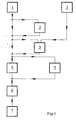
- Fig. 1 shows a schematic representation of a process flow from the preparation to the strand production of a filter of the tobacco processing industry.
- a fiber preparation 1 takes place, in which first of all the transfer of all the compressed forms of delivery of fibrous materials into an airy-wooly state is carried out. This should be loosened fiber groups. In addition to these fiber groups, individual fibers can already be produced.
- the fiber preparation 1 is carried out, for example, with a device according to FIG. 2. Such a device is known per se.
- To the compressed forms of delivery include, for example, fiber bales and fiber mats 10 and a fiber felt 10. fiber bales are usually unpacked by means of bale breaker and fiber mats 10 or fiber felt 10 by means of a hammer mill 13th
- a bale breaker for fibrous materials is obtainable, for example, from the company Trützschler and a hammer mill for fibrous materials, for example from the company Kamas.
- the optional in this embodiment possible is a pre-dosage 2.
- a predosing 2 is, for example. With the device of FIG. 3 possible. The pre-metering serves a coarse dosage of the fiber material and a further separation to the effect that the fibers present in groups or as dense packing are further loosened up. Also at this point more completely separated fibers can arise.
- a main metering or metering 4 alone can be carried out. Whether a pre-dosage 2 is necessary depends on the nature of the fiber preparation. The goal of the metering 4 and the predosing 2 is the realization of a defined stable uniform mass flow of fibers and in addition also already partly pre-separation.
- the dosing step 4 leads to a further separation of the fiber groups. It is possible to provide a mixing and / or dosing step 3 before the dosing step 4. In this step, a plurality of filter materials, as indicated in Fig. 1 by the leading into the box 3 ways, and optionally an additive such as a binder, for example, or an activated carbon granules are mixed.
- a binder for example, or an activated carbon granules
- the various Fiber materials continuously or discontinuously mixed together.
- a continuous mixing device 111 is shown.
- the mixing device 111 also performs a buffer storage function for the pulps.
- additives in solid or liquid form. These additives serve to bond the fibers together and / or favorably influence the filtration properties of the fiber filter.
- the discharge from the mixing device 111 is defined, whereby a metering function is given.
- a metering function is given.
- the fiber material is fed to a singulating step 6.
- the goal of the singulation is a complete dissolution of the remaining fiber groups in single fibers. This serves to regroup the individual fibers in the subsequent step of the strand production 7 in such a way that an optimum nonwoven structure can be formed in which no bridges and cavities are contained.
- fiber for fiber can be placed next to each other and so a fleece can be formed. It is thus possible according to FIG. 1 to use up to three dosing steps. It can also be preceded by further dosing stages of singling.
- the fiber stream emerging from the singling consists of individual fibers which are guided in air or in an air stream.
- the appearance of the air flow with the entrained fibers or a fiber flow laden with air is very similar to that of a snowstorm.
- the isolated fibers are fed, for example, with a fluidized bed to the suction belt of a special suction belt conveyor.
- Strangherstellen 7 is a Strand produced with constant cross-section, wherein the cross-section is particularly constant square, while a uniform density is produced.
- the fibers are present in a fleece-like structure.
- the finished fiber filter strand has sufficient hardness, draw resistance, constant weight, retention and further processing.
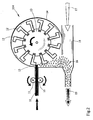
- FIG. 2 shows a fiber preparation device 114.
- a fiber field 10 is conveyed by means of feed rollers 11 into the effective region of a hammer mill 13 with hammers 12.
- the hammers 12 of the hammer mill 13 are housed in a housing 14.
- the hammers 12 strike the fiber felt and thus form fiber groups 16.
- the fiber groups 16 are transported further in a tube 18 by means of air flow 17.
- the result is a loaded with fiber groups air flow 19.
- already isolated fibers may have arisen.
- the hammers 12 of the hammer mill 13 rotate in the direction of fall, so that the fibers are ejected tangentially in the rotor rotation direction from the housing 14 of the hammer mill 13.
- a predosing 113 is shown schematically.
- An air stream loaded with fiber material 41 is fed to a separator 20, which separates the fiber material 41 from the air flow, so that fiber material 42 falls through the shaft 21 into the storage container 22.
- two spiked rollers 23 are arranged in the lower part of the storage container 22.
- the spiked rollers 23 rotate slowly and feed the fiber material to a third spiked roller 24.
- the third spiked roller 24 rotates rapidly and rips fiber groups out of the fiber material.
- These fiber groups enter the funnel 25 by sliding down.
- a rotary valve 26 is arranged. The fiber groups slip into the cells of the rotary valve 26 and are transported in the channel 27.
- the channel 27 there is an air flow 28, which takes the output into the channel 27 fibers or fiber groups with it.
- the air stream 28 also already carries along from the process recycled fibers, which are fed to the fiber groups.
- the airflow 29 is fully loaded with fibers and fiber groups. With the air flow, a fiber / fiber group mixture 29 is transported.
- the fiber / fiber group mixture 29 is introduced by means of an air flow into the separator 30 e.g. transported a rotary separator. There, the fiber / fiber group mixture is separated from the air flow.
- the separated fiber material 31 enters the stowage shaft 32 and falls in this down to the feed rollers 34. It can also be provided a plurality of pairs of rollers or a pair of feeder belts or several Einzugsb sectionplane. Vibrating elements 33 are provided in a section of the stacking shaft 32, by means of which a complete supply of the fiber / fiber group mixture 31 to the infeed rollers 34 is made possible.
- the feed rollers 34 convey the fiber material between the scrapers 35 into the metering channel 36 formed by them.
- a rotating roller 37 for example a spiked roller, tears the fibers out of the fiber material and inserts them into the channel 38.
- In the channel 38 prevails an air flow 39, which detects the fibers or the fiber material 40 and transported accordingly in the arrow direction.
- the mass flow rate of the metering channel 36 is specified.
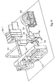
- FIG. 5 shows a mixing device 111 in a schematic, three-dimensional representation.
- Various fiber materials 43 and 44 as well as other fiber materials or additives 45 in liquid or solid phase are introduced into the mixing chamber 46.
- the fibrous materials may be cellulosic fibers, thermoplastic starch fibers, flax fibers, hemp fibers, flax fibers, sheep wool fibers, cotton fibers or multicomponent fibers, especially bicomponent fibers having a length of 2 to 100 mm and a thickness of, for example, 25 and 30 have ⁇ m.
- cellulose fibers stora fluff EF untreated from StoraEnso Pulp AB can be used, which have an average cross section of 30 ⁇ m and a length between 0.4 and 7.2 mm.
- synthetic fibers such as, for example, bicomponent fibers, fibers of the Trevira type, 255 3.0 dtex HM with a length of 6 mm from Trevira GmbH can be used. These have a diameter of 25 microns.
- synthetic fibers cellulose acetate fibers, polypropylene fibers, polyethylene fibers and polyethylene terephthalate fibers may be used.
- the flavor or the smoke influencing materials can be used as carbon reactive granules or flavoring agents and also binders, by means of which the fibers can be glued together.
- the fiber material 43 and 44 or the corresponding additives 45 introduced into the mixing chamber 46 are fed to rollers 50 to 52, which rotate at suitable rotational speeds during the filling and the mixing process.
- the position of the rollers 50-52 is preferably adjustable both horizontally and vertically. Thus, the center distances of the rollers are mutually adjustable. It can also be arranged several rollers in different floors.
- the components to be mixed are from the rollers 50 - 52 detected, accelerated and swirled in the mixing chamber 46. The confusion causes a mixing of the components.
- the residence time of the components to be mixed in the mixing chamber 46 is adjustable by the geometric nature of the screen 47.
- the residence time of the components to be mixed in the mixing chamber 46 is determined by the position of a thrust diaphragm, by means of which the openings of the screen 47 can be partially or even completely closed.
- the thrust diaphragm is not shown in the figure.
- the mixture of fibers 53 and, in general, the mixture 53 is conveyed through the openings of the screen 47 into the chamber 54. This can be done continuously or at intervals.
- the chamber 54 is preferably pivotable and is traversed by an air flow 55.
- the air flow 55 detects the mixture 53 and entrains it.
- the laden air stream 56 leaves the chamber 54 and passes the mixture 53 on.
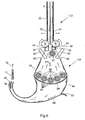
- FIG. 6 shows a diagrammatic illustration of a separating device 115 in connection with a metering device 112.
- the metering device 112 essentially corresponds to the metering device from FIG. 4, although the vibration elements 33 are shown as separate sections of the chute 32 and the strippers 35 have a slightly different shape than that in FIG. 4.
- the fiber material torn out of the dosing channel 36 by the rotating roller 37 is fed directly to a dicing chamber 61. About the speed of the feed rollers 34, the mass flow rate of the metering 36 is determined.
- the entire separating device is traversed by air. This flow 133 is caused by the negative pressure at the fluid bed end. This negative pressure arises on the one hand by the guided in the suction nozzle 71 air flow 72 and the other by the flow in Saugband makeuper, which is arranged at the fluidized bed end 69 and is not shown in this figure.
- the fibers or groups of fibers move under gravity and flow through the air flow 63 and air inlet 63, respectively, through the ventilation openings 62 into the area of the rollers 60.
- the rollers 60 of the row of rollers 60 engage the ununsulated fibers (and of course already partially isolated present fibers), accelerate them and beat them against the sieve 64 of the separation chamber 61.
- a sieve with corresponding sieve treads and perforated or round rod can be used.
- the fiber groups are dissolved in individual fibers and finally pass through the sieve 64. That is to say, after sufficient separation, the fibers are caught by the flow 133 passing through the sieve and guided or drawn through the sieve 64.
- the number of revolutions of the rollers 60 and the area as well as the magnitude of the flow 133 determine the mass flow rate of the singulating chamber 61 of the openings of the screen 64.
- the separated fibers 65 reach the fluidized bed 66 where they are detected by an air jet 68 emerging at the air nozzle, which is designed as a nozzle bar 67, and moved on the fluidized bed 66. There may also be provided a plurality of nozzle strips 67. Mainly the negative pressure applied at the fluidized bed end 69 ensures a sufficient flow 133 for conveying the separated fibers to the fluidized bed end 69.
- the flow 133 is partially separated by the flow divider 70 at the fluidized bed end 69 of the fiber flow and enters the suction nozzle 71st
- the flow generated by the negative pressure and the nozzle bar 67 extracts air from the separating chamber 61. Via the ventilation openings 62 in the separation chamber 61 air 63 flows after.
- the separated fibers are then transported in the air flow of the flow 133, which previously served for the separation. This happens almost vertically to the fluidized bed and then along the same.
- the flow 133 can be supplemented by further air flows, for example air flow 68.
- the fluidized bed 66 is followed by a suction belt conveyor, which is not shown in this figure (see in particular FIGS. 10 and 12).
- a suction belt conveyor On the suction belt, the scattered fibers are heaped up. It can also be used two suction belts or even more suction belts.
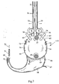
- Fig. 7 shows a further embodiment of a separating device.
- only one roller 60 is provided in this embodiment.
- a plurality of air streams 74 are provided in the separation chamber 61, which are generated by air nozzles 73. Multiple air nozzles 73 may be used as shown in FIG. These need not only be arranged on the chamber lateral surface, but may also be distributed in the separating chamber 61.
- the air streams supply the fibers of the roller 60. Instead of a roller, several rollers can be used.
- the function of the roller 60 or a plurality of rollers 60 corresponds to the function of FIG. 6.
- the air flows 74 result in an increased turbulence in the singling chamber 61, so that the singulation of the fibers is improved in comparison to the embodiment according to FIG ,
- the individual fibers 65 pass accordingly through the screen 64 as in the example of FIG. 6.
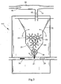
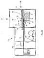
- FIG. 8 shows a further embodiment of a separating device 115.
- the air flow is hereby generated by the vacuum applied to the fluidized bed end 69 and the air flow 68 flowing out of the nozzle bar 67. It can also find multiple nozzle strips use.
- the main air flow begins above the screen 64, passes through the rows of agitators 82 and 83 and the screen 64. Thereafter, the main air flow enters the fluidized bed section 66 and passes through the fluidized bed 66 to its end.
- the essentially unaccurate fiber material or fiber / fiber group mixture 31 passes above the sieve 64 into the housing. This may also be inclined at an angle instead of the representation in FIG. 8, such as, for example, at 45 ° to the horizontal. Under the influence of gravity and under the influence of the main air flow, the fiber / fiber group mixture 31 reaches the area of the agitating tools 82 and 83.
- the rows of stirrers 82 and 83 consist of stirrers arranged behind one another, which drive a suitable stirring tool. The stirring tools are offset by 90 ° to each other. There may also be other displacement angles.
- the unclarified fiber groups are ruptured by the rotating stirrers, accelerated and struck against the screen 64 of the housing.
- the screen 64 can also be a perforated plate or a Rundstabgitter use.
- the fiber groups or the fiber group mixture 31 is thrown against the screen 64 until they have dissolved in individual fibers and have passed the screen 64 in the main air flow. Thereafter, as in the previous embodiments, the fibers reach the fluidized bed 66 and a suction belt conveyor which is not shown in FIG.
- the separating device shown in Fig. 8 with respect to at least the rows of stirrers 82 and 83 from EP 0 616 056 B1 of M + J Fibretech A / S, Denmark.
- the disclosure of EP 0 616 056 B1 is intended to be incorporated in its entirety in this patent application.
- FIG. 9 A further preferred embodiment of the separating device 115 is disclosed in FIG. 9 in a schematic three-dimensional representation.
- the essentially unaccurate fiber material or fiber / fiber group mixture is transported by the air streams 76 into the sieve drums 78. This is done via lateral openings 77 in the housing 79.
- the fiber material is blown in the direction of the longitudinal axes of the sieve drums 78.
- the two-sided blowing of the fiber material counterclockwise results in a circumferential annular flow 80.
- the annular flow 80 is superimposed by a flow normal or substantially perpendicular to this, which is caused by a negative pressure applied to the fluidized bed end 69 and an air flow 68.
- the negative pressure prevailing at the fluidized bed end 69 is produced by the negative pressure in a suction belt conveyor, not shown, which is arranged at the fluidized bed end 69 and, secondly, at the air flow 72 which is conveyed through the suction connection 71.
- the normal flow starts above the sieve drums 78 and passes through the sieve drums 78 via their shell openings.
- the normal flow then enters the fluidized bed region 66 and passes through it to the end 69, where a portion of the normal flow at the wedge 70 is separated from the fibers.
- the unaccurate fiber material passes in the drums 78 on the inner circumferential surfaces of the drums 78.
- the drums 78 rotate in a direction of rotation 81 of the screening drums 78 in a clockwise direction.
- the stored on the drum shell surfaces, essentially unaccompanied fiber material is from the rotating drums fed to the separating rollers 85.
- the separating rollers 85 rotate in the direction of rotation 84 of the separating rollers 85 in the counterclockwise direction. It would also be possible as an alternative, a clockwise rotation.
- the separating rollers 85 and needle rollers detect the unclassified fiber groups and tear them and accelerate them.
- the fiber groups are thrown against the inner circumferential surface of the drums 78 until they have dissolved into individual fibers and have passed through the shell openings, ie are caught by the air flow (the normal flow) and are guided or sucked through the sieve drum 78.
- a drum with perforated plates or Rundstabgitter can be provided instead of a sieve drum 78.
- the fibers or individual fibers are detected by an air flow and guided or sucked through the radial openings of the drum.
- the air flow conveys the fibers down to the fluidized bed. Once the fiber-laden flow has reached the fluidized bed, it is deflected and guided along the curved fluidized bed. Due to the centrifugal forces acting on the fibers, the fibers move to the curved guide wall and flow to the suction belt conveyor.
- the air flowing in above the fibers is deposited on the wedge or separator 70 and discharged via the suction connection 71.
- Fig. 9 the corresponding fiber streams 75 are shown schematically. There are isolated fibers detected by an emerging from the nozzle bar 67 air flow 68 and correspondingly fed to the fluidized bed end 69, as well as reaching the fluidized bed 66 separated fibers through the air flow 68. It can also be provided several nozzle strips.
- For singling the fibers pass through the openings 132 of the screening drums 78. Essentially, only a few fibers can pass through the openings 132.
- the openings 132 are thus configured such that only isolated fibers can pass through.
- the separating device shown in FIG. 9 corresponds at least in part to those disclosed in WO 01/54873 A1 or US Pat. No. 4,640,810 A of Scanweb, Denmark, or USA.
- the disclosure of the aforementioned patent application or of the aforementioned US patent is intended to be incorporated in full in the disclosure content of this patent application.
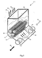
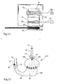
- FIG. 10 shows a schematic representation of a strand production machine 110.
- FIG. 11 shows a part of the strand production machine 110 in a plan view in the direction of the arrow A and FIG. 12 shows a side view of the strand production machine 110 according to FIG. 10 in the direction of the arrow B.
- the unaccurate fiber material passes via the stowage chamber 32 to the metering device 34, which in this example is a pair of intake rollers 34 with a rotating roller 32.
- the direction of the material entry 100 is in FIG. 11 in the drawing plane downwards, as shown schematically there.
- the unclarified fiber material is singulated in the separation chamber 61.
- the air flow generated by the air flow in the suction nozzle 71 and the air stream 72 'in Saugband makeuper 89 on the fluidized bed 66 promotes the isolated fibers 65.
- the air flow 72 in the suction 71 is with respect 11, the direction of which is upward in FIG. 11 out of the plane of the drawing, as shown in FIG.
- the air stream 72 also removes excess fibers.
- the singulated fibers 65 move on the fluidized bed 66 toward the fluid bed end 69 where, as shown in the figures, a suction belt conveyor 89 is disposed.
- a suction belt conveyor 89 prevails by continuous air suction vacuum. This air suction is shown schematically by the air stream 72 '.
- the negative pressure sucks the separated fibers 65 and holds them on the air-permeable suction belt of the suction belt conveyor 89.
- the separated fibers 65 are snapped onto the air-permeable suction belt of the suction belt conveyor 89 accordingly.
- the suction belt 116 moves in the direction of strand production machine 110, that is to say in FIG. 10 to the left.
- a fiber cake 86 which increases linearly with respect to the stranding machine 110, is formed on the suction belt.
- the accumulated fiber stream 86 has different strengths and is trimmed at the end of the filling zone of the suction belt conveyor 89 by trimming by a trimming device 88 to a uniform thickness.
- the trim device 88 may be a mechanical one such as trimmer discs or a pneumatic one by means of, for example, air nozzles. The mechanical trim is known per se in cigarette rod making machines.
- the pneumatic trimming is done in such a way that horizontally at the end of the fiber stream 86 a nozzle is arranged, from which an air jet emerges and tears off part of the fiber stream 86, so that excess fibers 87 are removed. It can find a spot jet nozzle or a flat jet nozzle use.
- the fiber stream 86 is split into a trimmed one Fiber strand 90 and a strand of excess fibers 87. It is also possible to detect and tear away all fibers below a trim level from a jet. The excess fibers are returned to the fiber preparation process and later re-formed into a fiber strand.
- the trimmed fiber strand 90 is held on the suction belt 116 and moved in the direction of the stranding machine 110.
- the trimmed fiber strand 90 is a loose nonwoven fabric that is compacted by a compacting belt 92.
- the compression belt 92 may also find a role use. It can also find multiple bands or roles use.
- the compression belts 101 are shown, which are conical to each other and in Saugband york with the fiber cake.
- the toothed shape of the compaction belts 101 create zones of different density in the compacted fiber cake. In the higher density zones, the filter strand is cut later.
- a compression belt 92 is provided for compressing in the vertical direction. Instead of the compression belt 92 and rollers may be provided.
- the trimmed and compacted fiber strand 91 is transferred to the stranding machine 110.
- the transfer takes place by the detachment of the compacted fiber strand 91 from the suction belt 116 and the application of the fiber strand 91 onto a format belt of the stranding machine 110.
- the format belt is not shown in the figures. This can be a usual format tape, which also works for a normal filter rod machine or cigarette rod machine is used.
- the transfer is supported by a nozzle 93 directed from above onto the compacted fiber strand 91, through which an air stream 94 passes.
- a fiber filter strand 95 is produced, wherein from a bobbin 98, a wrapping material strip 99 is wound around the fiber material as usual.
- a certain internal pressure builds up in the fiber filter strand 95.
- binder components contained in the fiber mixture are superficially heated and fused. Accordingly, the outer layers of bicomponent fibers can be melted, so that a connection between the fibers is formed.
- the curing device 96 may also include a microwave heater, a laser heater, heating plates or sliding contacts.
- the individual fibers combine in the fiber strand and merge superficially.
- the melted areas harden again.
- the resulting lattice framework gives the fiber strand stability and hardness.
- the cured fiber filter strand 95 is cut into fiber filter rods 97. The curing of the fiber filter is possible even after cutting into the fiber filter rods 97.
- FIG. 13 shows a three-dimensional schematic illustration of a fifth embodiment of the separating device according to the invention, which is similar to that of FIG. 9.
- a granule metering device 120 is also provided.
- the granulate dosing device 120 scatters granules between the screening drums 78 and the separating device 115 over the entire width of the separating device 115.
- the interspersed granules 121 mix in the area of the screening drums 78 with the fibers emerging from the screening drums 78.
- the result is a mixture of isolated fibers and granules, which is in the air flow on the fluidized bed to Saugstrang makeuper, which is arranged in the conveying direction behind the Saugstrangende 79.
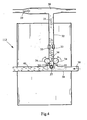
- FIG 14 shows a schematic cross-sectional view of a further separating device 115.
- the air flow is improved, so that more uniform fiber streams 75 and 75 'are produced.
- An airflow 122 enters the device at the top of the screen drum 78.
- the separated fibers emerging from the screening drums 78 pass into channels 123 and 124 and are guided downwards into the region of the fluidized bed 66 by the corresponding air flow.
- the fiber streams 75 are combined to form a fiber stream 75 '.
- a majority of the transport air is separated from the fiber stream, which is represented by the air stream 122 '.
- a suction nozzle 125 is provided in the rolling space of the fluidized bed 66.
- the fiber stream 75 passes after the union of the two fiber streams 75 in a channel formed by the fluidized bed 66 and the separator 127. Depending on the process, it may be possible at this point that a fleece has already formed or else it may also be the case that the fibers are still separated.
- the fiber stream 75 'becomes then transported by the voltage applied to Saugbandageer 89 negative pressure to the fluidized bed end 69 and the Saugband makeuper 89.
- Fig. 15 shows a corresponding schematic sectional view, which is similar to that of FIG. 14.
- a granule dosing device 120 is arranged above the sieve drums 78. From two sampling nozzles 78 granules 121 is fed to the respective sieve drums. The formed fiber / granule stream 128, which is transported in the channels 123 and 124, is combined in the lower region of the fluidized bed 66 and into a fiber / granular stream 128 '.
- FIG. 16 illustrates another embodiment of a dicing device 115 according to the invention.
- the addition of granules 121 from the granule dosing device 120 is performed near the fluidized bed end 69.
- Granules 121 reach an acceleration element 129, which may be a roller, a brush or a nozzle.
- the accelerated granules 121 pass through the line 130 into the fluidized bed, namely into a vertical fluidized bed section 131.
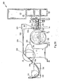
- a filter strand manufacturing device is shown schematically in side view in FIG. 17.
- the method to be carried out with this device is used to produce cigarette filters made of suitable fibrous materials of biological and / or synthetic origin and also other materials such as granules, for example.
- the filter materials may be those already described above.
- the filters produced which can also be called fiber filters, are partly or completely biodegradable, depending on the fiber mixture.
- a nonwoven forms of the filter strand, or as a filter strand form a round or oval cigarette filter may be sought, which is produced at the end of the manufacturing process.
- the device shown in FIG. 17 processes two different fibers which are supplied to the fluidized bed 216 at two metering points of two filter material supply devices, namely a metering opener 209 and a fiber mill 201.
- the first metering point is the transition of the fiber mill 201 into a fiber channel 215, which is immediately followed by the fluidized bed 216.
- a cellulose raw material such as cellulose acetate fibers are in the form of a nonwoven 223 rolled up on a bobbin 202.
- the nonwoven fabric 223 is fed to the fiber mill 201 via a feed roller pair 204 driven by a motor 203.
- a rotary cutter drum 207 driven by a motor 205, fiberizes cellulose plates or the cellulosic web at high speed.
- the cutterhead 207 has a plurality of cutter disks.
- the plurality of milling discs 207 are more clearly seen in Fig. 18, which is a plan view of the device of Fig. 17 in a schematic representation.
- the cellulose fibers are introduced via separator plates 208 into a strong transport air stream 206.
- the second metering point is at a point 214 in the region of the fiber channel 215, in which the outlet of the metering opener 209 is located.
- the meter opener 209 is preceded by a bale opener 226, which is shown in Fig. 19.
- a corresponding bale opener 226 can be purchased, for example, from Trützschler, Germany.
- the existing in the form of bales or stacks of fiber material is isolated in the bale opener 226 or isolated to a high degree.
- the fibrous material may comprise, for example, bicomponent fibers.
- the isolated or pre-separated fibers are supplied to the dosing opener 209 by means of transport air via a pipeline 210. In the dosing opener 209, the fibers are separated from the transport air by means of the sieve 228 and fall into a reservoir shaft 211.
- the reservoir or the reservoir shaft 211 in which the fibers are deposited, or fall into it, serves to compensate for fluctuating flow rates of the bale opener, which can arise, for example, by a bale change.
- the reservoir is thus necessary to allow continuous metering of fibers in a production process.
- Benadelte transport rollers 212 convey by their rotational movement, the fibers on the needled metering roller 213. By speed variation of the rotating parts of the mass flow rate is adjustable.
- the fibers are combed out of the needles by the transport air stream 206 and completely separated. This can also be supported by appropriate Abscheiderbleche, which are not shown. Subsequently, the fibers are conveyed in the fiber channel 215 and fed to the fluidized bed 216.
- the mass flow rate of the fiber mill 201 is effected by controlling or regulating the feed of the material in the form of the nonwoven 223 into the fiber mill 201.
- the transport air stream 206 flows through the two supply channels 229 and 230 shown in FIG. 17, so that first in each feed channel different filter material is conveyed separately from the other filter material.
- the feed channels are separated by a partition wall 231.
- the two supply channels 229 and 230 connect at the point 232 to a fiber channel 215. This is preferably rectangular. From this point, the fiber channel is to be designated as a fluidized bed 216.
- the at least two fiber materials combine in the fluidized bed 216 to form a homogeneous fiber mixture.
- the fluidized bed 216 describes a smooth curve function that is tangential to the fiber channel 215. About the lower and the lowest point 217 to the vertical inlet cheek of Saugstrangkanals 218, the curve describes the quadrant of an ellipse. At the end point of the fluidized bed 216, at which the fluidized bed merges into the suction channel 218, there is the strongest curvature of the curve. Due to the increasingly narrowing radius of curvature in conjunction with the speed of the fibers, the fibers increasingly deposit themselves on the lower sheet-metal wall or fluid-bed wall 227 due to the centrifugal force. In the area of the strongest curve curvature, the greatest centrifugal force prevails. In close proximity to this point or location 219, the fluidized bed 216 splits again into two channels. The lower, fiber-leading, channel opens into the Saugstrangkanal 218th
- the upper, ideally largely fiber-free, channel serves to discharge the large transport air flow from the system. Unsprayed fibers can be deposited and reused in a satisfactorily separator.
- the transport air stream 206 is in part by a to the Saugstrang Wegner 221 connected fan generates in the Saugstrang considerer and in the fluidized bed a negative pressure.
- the necessary air volume flow 206 for the operation of the fiber mill 201 and the Dosieröffners 209 is not only generated by the Saugstrangventilator alone.
- a second additional fan connected to fluid bed separator 220 generates the additional necessary transport air stream 206.
- the ratio of the volume of air to be extracted at the separation point or location 219 is influenced by the desired air velocities and the line cross section. Furthermore, the air volume flows in the two lines can be adjusted after separation by controlling the two fans.
- a fiber cake or a non-woven fabric is formed, which is conveyed on continuously by the suction belt, namely into a filter rod machine 222, which is shown in FIGS. 18 and 19.
- filters are made as usual, for example on a machine of the applicant, which is called KDF, or as described in the European patent application 03 007 675.6 entitled "Method and apparatus for producing a filter strand" of the applicant.
- KDF European patent application 03 007 675.6 entitled "Method and apparatus for producing a filter strand" of the applicant.
- the different types of fibers are fed via different metering systems at different locations to the feed channel of a fluidized bed.
- the transport air for the fibers is conveyed via the fan of the suction belt conveyor connected to the fluidized bed and via a fan generated at the fluidized bed.
- FIG. 18 also shows the filter strand 225 produced, which is conveyed in a conveying direction which is indicated by the arrow on the filter strand 225.
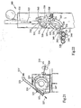
- FIG. 19 shows an arrangement of corresponding machines to be used for a filter-strand production device according to the invention.
- a filter rod machine 222 which is similar in construction to a cigarette rod machine, but is adapted to the properties of the other compared to tobacco fibers material (different filter fiber materials, or granules or powder).
- a further Filterstrangherstell sensible invention is shown schematically.
- the binder fibers such as bicomponent fibers are added to the filter manufacturing process at a first location, whereas filler fibers such as cellulose fibers from a fiber mat 303 and a nonwoven 303 from a reel 302 are fed to the binder fiber stream on a fiber mill rotor 307 and by action the cutter drum 307 are mixed.
- Binding fibers are metered and processed in a dosing and processing device 309.
- the dosing and processing device 309 is arranged upstream of a fiber mill 301.
- the dosing and conditioning device 309 discharges binding fibers 323 from the roller 328 to an air flow 306.
- the operation of the dosing and processing device 309 will be described in more detail below.
- binder fibers multicomponent fibers, especially bicomponent fibers come into question. For this purpose, reference is made in particular to DE 102 17 410.5 of the Applicant.
- the air stream 306 is guided in the channel 326.
- the air flow 306 in the channel 326 and also in the fluidized bed channel 316 is generated either alone or substantially by the rotation of the cutterhead 307 in the channel region 325 of the channel 326.
- the air stream 306 is further assisted by the fan or a suction air blower on the suction belt conveyor 321 and the fan or a circulating air blower, which sucks air from the fluidized bed separator 320 and led out of the process.
- the fan or fan 329 optionally supports the airflow 306.
- the air stream 306 loaded with binding fibers 323 enters the channel region 325 on the milling drum 307.
- the feed rollers 304 convey a fiber mat or nonwoven fabric 303 from the reel 302 to the milling drum 307.
- the milling drum 307 treats the nonwoven fabric 303 into single fibers 324.
- the single fibers 324 are tumbled by the cutterhead 307 into the channel region 325 of the channel 326 where they are mixed with the binding fibers 323.
- the fiber mixture 327 is transported by the air stream 306 from the channel 326 in the fluidized bed channel 316. It is possible in this device according to the invention to add granules to the fiber mixture 327 between the channel 326 and the fluidized-bed channel 316 via a feed shaft 330.
- the binder fibers 323 may also be a blend of different fibers, such as a blend of polypropylene fibers and bicomponent fibers.
- the dosing and conditioning device 309 may serve.
- Fig. 21 shows the detail A of the device according to the invention from Fig. 20 in a schematic view, wherein the sheath of the fiber mill 301 has been removed.
- the mixture of the bicomponent fibers 323 or binding fibers 323 with the individual fibers 324 is illustrated particularly well with the aid of the milling drum 307.
- the conveying direction 323 'of the binding fibers 323 and the conveying direction 327' of the fiber mixture 327 are also shown.
- the conveying direction 310 of the fleece 303 is shown.
- the binder fibers 323 and, alternatively, any fiber blends such as bicomponent binder fibers and polypropylene filler fibers are filled into the well 331.
- the dosing and conditioning device 309 is shown schematically in more detail in Fig. 22 in a particular embodiment.
- the fibers 323 move down the shaft 331. At the lower end of the shaft 331, the fibers 323 are caught by the slow-running feed roller 332.
- the feed roller 332 conveys the fibers 323 against a spring-loaded trough 333.
- the fibers 323 are drawn in and compacted into a thin compact fiber cake, which is not shown.
- the fiber cake which is conveyed downwards between the feed roller 323 and the trough 333, is then milled off at the lower end of the trough 333 by the fast-running drum roller 334.
- the fibers 323 are loosened, separated and introduced into the air flow 339 in the shaft 335.
- the fan 338 generates a recirculated airflow 339.
- the airflow 339 is guided in the channel 340 and then past the feed roller 332. In this case, the air flow 339 cleans the feed roller 332. Subsequently, the air flow 339 absorbs fibers 332 and transports them down into the shaft 335.
- the shaft 335 in the region 336 is designed so that the shaft walls are formed in top and bottom in comb shape, that is, that there are recesses through which air can flow.
- the air flow 339 is deposited by the fibers 323 via the combs, which are not shown in FIG. 22.
- the fan 338 sucks the air stream 339 out of the comb area 336 via the pipes 337. The circulation of the air flow 339 is thus closed.
- the fibers deposited by the air flow 339 are detected at the end by the shaft 335, namely behind the comb region 336, by the slow-moving feed roller 343 and conveyed against the trough 341 and subsequently a leaf spring battery 342.
- the trough 341 is spring-mounted. The result is a thin, compact fiber cake, which is not shown and which is conveyed and compressed between the feed roller 343, the trough 341 and the leaf spring battery 342.
- rollers 344, 345 and 328 are equipped with sawtooth or Trapez leopardgarnituren. The roller speeds are increasing from roller 344 to roller 328.
- the fibers 323 After the fibers 323 have been held in the set of roll 344 for a rotation of about 180 °, the fibers 323 are tangentially transferred to the counter rotating roll 345. Since the roller 345 rotates faster than the roller 344 and in particular has a finer Sge leopard- or Trapez leopardgarnitur, there is a longitudinal alignment, parallelization and separation of the fibers in the transfer.
- the fibers 323 in the clothing of the roller 345 After the fibers 323 in the clothing of the roller 345 have been kept approximately 180 ° long, the fibers 323 are transferred tangentially to the in turn counter rotating roller 328. Since the roller 328 rotates faster than the roller 345 and in particular has a finer Sge leopard- or Trapez leopardgarnitur, there is a longitudinal alignment, parallelization and separation of the fibers in the transfer. After the fibers 323 in the set of roll 328 have been held at approximately 180 °, the fibers 323 are ejected tangentially upwardly in the air stream 306 into the channel 326.
Abstract
Description
Die Erfindung betrifft ein Verfahren zur Herstellung eines Vlieses für die Herstellung von Filtern der tabakverarbeitenden Industrie. Die Erfindung betrifft ferner eine Filterstrangherstelleinrichtung der tabakverarbeitenden Industrie, umfassend wenigstens eine Filtermaterialzuführvorrichtung, aus der das Filtermaterial dosiert abgebbar ist und eine Strangaufbauvorrichtung, in der das Filtermaterial zu einem Strang ausbildbar, insbesondere aufschauerbar, ist.The invention relates to a process for producing a nonwoven fabric for the production of filters of the tobacco processing industry. The invention further relates to a Filterstrangherstelleinrichtung the tobacco processing industry, comprising at least one Filtermaterialzuführvorrichtung, from which the filter material is metered dispensed and a strand-building apparatus in which the filter material can be formed into a strand, in particular aufschauerbar.
Ein Verfahren zur Herstellung eines Vlieses für die Herstellung von Filtern der tabakverarbeitenden Industrie und eine entsprechende Filterstrangherstelleinrichtung der tabakverarbeitenden Industrie ist aus der GB 718 332 bekannt. Hierbei werden mittels einer Tabakschneidemaschine Schnipsel eines Materials hergestellt und diese einer Strangmaschine, ähnlich einer Zigarettenstrangmaschine, zugeführt, wobei die Schnipsel mit einem chemischen Mittel imprägniert werden, um einen ungewünschten Geschmack zu verhindern und zu verhindern, dass die Schnipsel aus den Endstücken der entsprechend hergestellten Filter herausfallen. Die geschnittenen Schnipsel werden mittels einer Trommel in den Wirkbereich einer Stachelwalze gefördert und mittels der Stachelwalze von der Trommel auf ein Förderband gefördert, um anschließend einer weiteren Fördertrommel zugeführt zu werden, aus der die Schnipsel mittels einer weiteren Stachel- bzw. Schlägerwalze ausgeschlagen werden und einem Format zugeführt werden, in dem der Filterstrang mit einem Umhüllungsstreifen gebildet wird. Die Schnipsel aus Materialien wie Papier, Cellulose, Textilien, synthetische Materialien oder ähnlichem, haben eine ähnliche Struktur wie geschnittener Tabak.A process for producing a nonwoven fabric for the manufacture of filters of the tobacco processing industry and a corresponding filter strand manufacturing facility of the tobacco processing industry is from GB 718 332. Here, by means of a tobacco cutting machine, snippets of a material are prepared and fed to a stranding machine, similar to a cigarette rod making machine, which chips are impregnated with a chemical agent to prevent undesirable taste and to prevent the chips from ending in the correspondingly made filters fall out. The cut chips are conveyed by means of a drum in the effective range of a spiked roller and conveyed by the spiked roller from the drum on a conveyor belt to be subsequently fed to a further conveyor drum, from which the chips are knocked out by a further spiked or racket roller and a Be fed format in which the filter strand is formed with a wrapping strip. The snippets of materials such as paper, cellulose, textiles, synthetic materials or the like, have a similar structure as cut tobacco.
Aufgrund der Form der Schnipsel ist es nur schwer möglich, Filter mit homogenen Eigenschaften herzustellen. Außerdem ist die Variabilität der Einstellung der Filtereigenschaften nur sehr bedingt möglich.Due to the shape of the chips, it is difficult to produce filters with homogeneous properties. In addition, the variability of the setting of the filter properties is only possible to a very limited extent.
Die US-A-4 640 810 beschreibt eine Vereinzelungsvorrichtung, bei der ein so genanntes air-laid Vlies aus Fasern auf ein Förderelement aufgebracht wird. Hierbei werden entsprechende Umluftsysteme und sich drehende Trommeln und Walzen verwendet. Bei einem Vlies gemäß diesem Dokument handelt es sich um ein Material, das aus Fasern besteht, wobei die Fasern derart aneinander anliegen oder miteinander verbunden sind, dass eine luftdurchlässige Matte erzeugt wird.US Pat. No. 4,640,810 describes a separating device in which a so-called air-laid web of fibers is applied to a conveying element. Here, appropriate air circulation systems and rotating drums and rollers are used. A nonwoven according to this document is a material which consists of fibers, wherein the fibers abut each other or are connected to one another in such a way that an air-permeable mat is produced.
Aus der GB-A-2 101 642 ist eine Schneidevorrichtung offenbart, mittels der kontinuierlich ein faseriges Material in Fasern zerschnitten wird, wobei die zerschnittenen Fasern einem kontinuierlichen Strom zugeführt werden, wobei insbesondere durch einen Gasstrom die Förderung der Fasern zumindest unterstützt wird. Aus den Fasern können Filterstäbe für Zigaretten hergestellt werden.From GB-A-2 101 642 a cutting device is disclosed by means of in that a fibrous material is continuously cut into fibers, wherein the cut fibers are supplied to a continuous stream, wherein the conveying of the fibers is at least assisted in particular by a gas flow. From the fibers filter rods for cigarettes can be produced.
Die US-3 644 078 offenbart eine Vorrichtung zur Herstellung einer Art Vlies, wobei mittels eines Luftstroms die Fasern auf ein Förderband aufgeschauert werden und anschließend auf ein weiteres Förderband übergeben werden. Ferner ist auch ein Trockner vorgesehen.US Pat. No. 3,644,078 discloses a device for producing a type of nonwoven, wherein the fibers are thrown onto a conveyor belt by means of an air flow and subsequently transferred to a further conveyor belt. Furthermore, a dryer is also provided.
Die US-A-3 834 869 offenbart ein Verfahren und eine Vorrichtung zur besseren Verteilung von Fasern und Teilchen in einer flüssigen Suspension, wobei zuerst eine entsprechende Verteilung der Fasern oder Partikel in einem Gas vorgesehen ist, wobei die Fasern oder Partikel dann auf ein Förderelement aufgebracht werden. Das Förderelement ist ein sich bewegendes Band.US-A-3 834 869 discloses a method and apparatus for better distribution of fibers and particles in a liquid suspension, wherein first a corresponding distribution of the fibers or particles in a gas is provided, the fibers or particles then being placed on a conveyor element be applied. The conveyor element is a moving belt.
Die US-A-3 792 943 offenbart eine Vorrichtung zur Herstellung eines Vlieses bzw. Gewebes aus natürlichen oder künstlichen Fasern wie Holzfasern, Textilfasern, Glas- oder Mineralwollfasern, Asbestfasern und dergleichen auf einem luftdurchlässigen Band mit einem Trocknungsprozess, bei dem ein fließendes Gas als Medium zum Aussortieren, Transportieren und Verteilen der Fasern Verwendung findet. Zunächst wird ein Fasermaterial mittels eines Transportbandes in einem Schauer zu einer Vereinzelungsvorrichtung verbracht, um von der Vereinzelungsvorrichtung in einen Luftstrom gefördert zu werden, der die vereinzelten Fasern an einer Wand vorbei in einen Raum befördert, an dessen unterem Bereich sich das Vlies aufschauern kann.US-A-3 792 943 discloses an apparatus for producing a web of natural or synthetic fibers such as wood fibers, textile fibers, glass or mineral wool fibers, asbestos fibers and the like on an air-permeable belt having a drying process using a flowing gas as Medium for sorting out, transporting and distributing the fibers is used. First, a fiber material is transported by means of a conveyor belt in a shower to a separating device, to be promoted by the separating device in an air flow that carries the individual fibers past a wall in a space on the lower part of the fleece can breeze.
Die GB-A- 2 165 136 offenbart eine Maschine zur Behandlung von Tabakfasern in einem Verteiler einer Zigarettenstrangmaschine.GB-A-2 165 136 discloses a machine for treating tobacco fibers in a distributor of a cigarette rod making machine.
Die GB-A-2 145 918 offenbart eine Vorrichtung zur Herstellung eines Füllmaterials, insbesondere für Zigarettenfilter, wobei zunächst aus einem endlosen Füllmaterial Fasern herausgelöst werden und entweder auf einem Förderband oder mittels eines Transportluftstromes zu einer Formatvorrichtung gefördert werden.GB-A-2 145 918 discloses an apparatus for producing a filling material, in particular for cigarette filters, wherein first fibers are dissolved out of an endless filling material and conveyed either on a conveyor belt or by means of a transport air flow to a formatting device.
Demgegenüber ist es Aufgabe der vorliegenden Erfindung, ein Verfahren zur Herstellung eines Vlieses für die Herstellung von Filtern der tabakverarbeitenden Industrie und eine gattungsgemäße Filterstrangherstelleinrichtung anzugeben, mittels der sehr homogene Filter herstellbar sind und die eine hohe Variabilität der Eigenschaften des herzustellenden Filters ermöglichen.In contrast, it is an object of the present invention to provide a method for producing a nonwoven fabric for the production of filters of the tobacco processing industry and a generic Filterstrangherstelleinrichtung by means of which very homogeneous filter can be produced and allow a high variability of the properties of the filter to be produced.
Gelöst wird diese Aufgabe durch Verwendung eines Fließbetts bei der Herstellung von Filtern der tabakverarbeitenden Industrie, wobei das Fließbett in Förderrichtung der Filtermateriallen stromaufwärts einer Strangaufbauvorrichtung angeordnet ist, wobei das Fließbett eine die Filtermaterialien führende gekrümmte Wand umfasst. Durch Verwendung eines Fließbetts, das auch Fließbettverteiler genannt werden kann, ist es gezielt und auf einfache Weise möglich, Filtermaterial, und insbesondere vereinzeltes Filtermaterial, dosiert in Richtung einer Strangaufbauvorrichtung zu fördern, wobei eine sehr gleichmäßige Förderung möglich ist, wodurch die Homogenität des hergestellten Filters hoch ist.This object is achieved by using a fluidized bed in the manufacture of filters of the tobacco processing industry, wherein the fluidized bed is arranged in the conveying direction of the Filtermateriallen upstream of a strand building apparatus, wherein the fluidized bed comprises a filter material leading curved wall. By using a fluidized bed, which can also be called a fluidized bed distributor, it is possible and easy to convey filter material, and in particular isolated filter material, metered in the direction of a strand-building device, wherein a very uniform promotion is possible, whereby the homogeneity of the filter produced is high.
Hierdurch ist es auch besonders gut möglich, einen möglicherweise verwendeten Transportluftstrom von dem Filtermaterial zu trennen, wodurch sehr gute Strangeigenschaften des aufgeschauerten Filtermaterials auf der Strangaufbauvorrichtung ermöglicht sind, wodurch ein homogener Filter erzeugt werden kann. Vorzugsweise ist die gekrümmte Wand in Förderrichtung zunächst abwärts gerichtet, in die Waagerechte übergehend, um anschließend aufwärts gerichtet zu sein.This also makes it particularly well possible to separate a possibly used transport air flow from the filter material, whereby very good strand properties of the aufgeschauererten filter material are made possible on the strand building apparatus, whereby a homogeneous filter can be generated. Preferably, the curved wall is initially directed downwards in the conveying direction, turning into the horizontal, in order to then be directed upward.
Die Aufgabe wird ferner durch ein Verfahren zur Herstellung eines Vlieses für die Herstellung von Filtern der tabakverarbeitenden Industrie mit den folgenden Verfahrensschritten gelöst:
- Zuführen von vereinzelten Filtermaterialien zu einem Fließbett,
- Transportieren bzw. Fördern des Filtermaterials in dem Fließbett im Wesentlichen mittels eines Transportluftstromes in Richtung einer Strangaufbauvorrichtung und
- Aufschauern des Filtermaterials auf der Strangaufbauvorrichtung.
- Supplying isolated filter materials to a fluidized bed,
- Transporting or conveying the filter material in the fluidized bed essentially by means of a transport air flow in the direction of a strand-building device and
- Shuddering of the filter material on the strand building apparatus.
Als Strangaufbauvorrichtung eignet sich insbesondere ein Strangförderer, der ein luftdurchlässiges Fördermedium wie bspw. ein Förderband umfasst.In particular, a strand conveyor which comprises an air-permeable conveying medium such as, for example, a conveyor belt is suitable as a strand-building device.
Durch das erfindungsgemäße Verfahren ist es möglich, sehr homogene Vliese für die Herstellung von Filtern der tabakverarbeitenden Industrie herzustellen, so dass die erzeugten Filter aus diesem Vlies auch sehr homogen sind. Wenn das Filtermaterial Fasern umfasst, ist zudem eine besonders hohe Variabilität der Einstellung der Filtereigenschaften möglich.The inventive method, it is possible to produce very homogeneous nonwovens for the production of filters of the tobacco processing industry, so that the filter produced from this nonwoven are also very homogeneous. In addition, if the filter material comprises fibers, a particularly high variability in the adjustment of the filter properties is possible.
Ein Verfahren zur Aufbereitung von Filtermaterial zur Verwendung bei der Herstellung von Filtern der tabakverarbeitenden Industrie weist die folgenden Verfahrensschritte auf:
- Zuführen endlicher Fasern zu einer Vereinzelungsvorrichtung,
- Vereinzeln der Fasern und
- Transportieren der vereinzelten Fasern in Richtung einer Strangaufbauvorrichtung.
- Feeding finite fibers to a singulation device,
- Separating the fibers and
- Transporting the separated fibers in the direction of a strand-building device.
Durch Verwendung von endlichen Fasern als Filtermaterial und durch ein im wesentlichen vollständiges Vereinzeln dieser Fasern vor dem Bilden des Stranges, aus dem im folgenden der Filter gebildet wird, ist es möglich, sehr homogene Filtereigenschaften zu erzielen. Hierbei ist gerade das im wesentlichen vollständige Vereinzeln der Fasern von besonderer Wichtigkeit, da nur vereinzelte Fasern, die anschließend wieder zu einem Vlies aus den vereinzelten Fasern umgebildet werden, es ermöglichen, ein Vlies mit gleichmäßiger und homogener Dichte herzustellen.By using finite fibers as the filter material and substantially completely separating these fibers prior to forming the strand from which the filter is subsequently formed, it is possible to achieve very homogeneous filtration properties. Here, just the essentially complete separation of the fibers is of particular importance, since only isolated fibers, which are then transformed again into a nonwoven fabric from the singulated fibers, make it possible to use a fleece produce uniform and homogeneous density.
Das Erscheinungsbild eines Stromes aus vereinzelten Fasern ähnelt dem eines Schneesturmes, also einem Strom von Fasern, der eine homogene statistische Verteilung der Fasern sowohl räumlich als auch zeitlich aufweist. Insbesondere bedeutet das vollständige Vereinzeln der Fasern, dass im Wesentlichen keine Gruppen von Fasern, die miteinander verbunden sind, mehr vorhanden sind. Erst nach dem Vereinzeln der Fasern wird wieder ein Verbund der Fasern bspw. eine vliesartige Struktur hergestellt. Durch Auflösung der Fasergruppen, durch Vereinzelung der Fasern in Einzelfasern, kann anschließend ein Vlies hergestellt werden, der keine Brücken und Hohlräume enthält.The appearance of a stream of isolated fibers resembles that of a snowstorm, that is, a stream of fibers that has a homogeneous statistical distribution of fibers both spatially and temporally. In particular, the complete singulation of the fibers means that substantially no groups of fibers that are connected to each other are present anymore. Only after the separation of the fibers is a composite of the fibers, for example, a nonwoven structure produced again. By dissolving the fiber groups by separating the fibers into individual fibers, it is then possible to produce a nonwoven which contains no bridges and cavities.
Wenn das Transportieren der vereinzelten Fasern wenigstens teilweise mittels eines Luftstromes geschieht, können die vereinzelten Fasern, ohne Fasergruppen zu bilden, transportiert werden. Eine besonders bevorzugte Ausführungsform des Verfahrens liegt dann vor, wenn das Vereinzeln der Fasern wenigstens teilweise mittels eines Luftstroms geschieht. Hierdurch wird der Vereinzelungsgrad sehr hoch. Es wird viel Luft verwendet, um die Fasern zu vereinzeln. Im Fließbettbereich wird dann überschüssige Luft von dem Faserstrom wenigstens teilweise abgeschieden.When transporting the singulated fibers occurs at least partially by means of an air flow, the singulated fibers can be transported without forming fiber groups. A particularly preferred embodiment of the method is present when the separation of the fibers takes place at least partially by means of an air flow. As a result, the degree of separation is very high. A lot of air is used to separate the fibers. In the fluidized bed area, excess air is then at least partially separated from the fiber stream.
Wenn das Vereinzeln der Fasern wenigstens teilweise mittels eines Hindurchtretens durch Öffnungen einer mit einer Mehrzahl von Öffnungen versehenen Vorrichtung geschieht, ist ein hoher Wirkungsgrad bei der Vereinzelung möglich. Wenn das Zuführen der Fasern wenigstens teilweise mittels eines Luftstromes geschieht, verbleiben vorvereinzelte Fasern beim Zuführen im Wesentlichen vereinzelt. Vorzugsweise werden die vereinzelten Fasern und auch die Fasergruppen, die vorm (im Wesentlichen vollständigen) Vereinzeln der Fasern aufbereitet werden, im Wesentlichen nur mit Transportluft bzw. einem Luftstrom zugeführt.When the singulation of the fibers occurs at least in part by passing through openings of a device provided with a plurality of openings, a high efficiency of singulation is possible. When the feeding of the fibers is at least partially effected by means of an air flow, pre-separated fibers remain substantially isolated during the feeding. Preferably, the singulated fibers and also the fiber groups which before (substantially complete) singulation of the Are processed fibers, essentially supplied only with transport air or an air stream.
Wenn wenigstens zwei Vereinzelungsschritte vorgesehen sind, wird ein höherer Grad der Vereinzelung der Fasern erreicht. Vorzugsweise geschieht eine Vorvereinzelung von in einem Verbund vorliegenden endlichen Fasern. Hierzu wird vorzugsweise eine Hammermühle oder ein Ballenauflöser verwendet. Eine Hammermühle findet dann Anwendung, wenn ein Faserfilz zur Verfügung gestellt wird. Ein Ballenauflöser findet dann Anwendung, wenn ein Faserballen zur Verfügung gestellt wird.If at least two singulation steps are provided, a higher degree of singulation of the fibers is achieved. Pre-separation of finite fibers present in a composite preferably takes place. For this purpose, a hammer mill or a bale breaker is preferably used. A hammer mill is used when a felt is provided. A bale breaker is used when a fiber bale is provided.
In einer bevorzugten Weiterbildung des erfindungsgemäßen Verfahrens ist wenigstens ein Dosierungsschritt vorgesehen, mittels dem die Menge der Fasern, insbesondere vorgebbar, dosiert wird. Es kann hierbei eine Vordosierung und/oder eine Hauptdosierung vorgesehen sein. Mittels der Vordosierung wird grob der Durchsatz der aufzubereitenden Fasern eingestellt. Mittels der Hauptdosierung wird eine feinere Einstellung ermöglicht.In a preferred development of the method according to the invention, at least one metering step is provided, by means of which the quantity of fibers, in particular that which can be predetermined, is metered. It may be provided in this case a predosing and / or a main dosage. By means of the pre-metering, the throughput of the fibers to be processed is roughly adjusted. The main dosage allows a finer adjustment.
Wenn wenigstens ein Dosierungsschritt gleichzeitig mit einem Vereinzelungsschritt geschieht, ist eine besonders effektive und schnelle Verfahrensführung möglich.If at least one dosing step occurs simultaneously with a dicing step, a particularly effective and fast process control is possible.
Vorzugsweise finden verschiedene Fasersorten Verwendung, so dass Filter mit den verschiedensten Filtereigenschaften herstellbar sind. Als Fasermaterialien kommen bspw. Celluloseacetat, Cellulose, Kohlefasern und Mehrfachkomponentenfasern, insbesondere Bikomponentenfasern in Frage. Bezüglich der in Frage kommenden Komponenten wird insbesondere Bezug genommen auf die DE 102 17 410.5 der Anmelderin.Preferably, different fiber types are used, so that filters with a wide variety of filter properties can be produced. For example, cellulose acetate, cellulose, carbon fibers and multicomponent fibers, in particular bicomponent fibers, are suitable as fiber materials. With regard to the components in question, reference is made in particular to
Vorzugsweise werden die verschiedenen Fasersorten gemischt. Es ist ferner möglich, wenigstens ein Additiv hinzuzufügen. Bei dem Additiv handelt es sich bspw. um ein Bindemittel wie Latex oder um Granulatmaterial, das besonders effektiv Bestandteile des Zigarettenrauches bindet wie bspw. Kohleaktivgranulat.Preferably, the different fiber types are mixed. It is also possible to add at least one additive. The additive is, for example, a binder such as latex or granular material, which binds components of the cigarette smoke particularly effectively, such as, for example, activated carbon granules.
In einer besonders bevorzugten Ausführungsform des Aufbereitungsverfahrens geschieht eine vollständige Vereinzelung mit oder im Anschluss an einen zweiten oder dritten Dosierungsschritt, wobei diese nach einem dritten Dosierungsschritt insbesondere beim Vorsehen einer Vordosierung ermöglicht ist.In a particularly preferred embodiment of the treatment process, a complete separation takes place with or following a second or third dosing step, which is made possible after a third dosing step, in particular when providing a pre-dosing.
Besonders bevorzugt ist es, wenn die Faserlänge kleiner ist als die Länge des herzustellen Filters. Bezüglich der Faserlänge wird auch vollumfänglich auf die DE 102 17 410.5 der Anmelderin verwiesen. Die Länge der Fasern soll demnach zwischen 0,1 mm und 60 mm und insbesondere zwischen 0,2 mm und 10 mm liegen. Bei künstlich hergestellten Fasern soll die Faserstärke 1 bis 20 dtex, bevorzugt 2 bis 6 dtex, betragen. Bei der Länge des herzustellenden Filters handelt es sich um einen üblichen Filter für eine Zigarette bzw. ein Filtersegment beim Multisegmentfiltern von Zigaretten. Wenn außerdem der mittlere Faserdurchmesser im Bereich von 10 bis 40 µm, insbesondere 20 bis 38 µm, liegt und besonders bevorzugt zwischen 30 und 35 µm, ist ein sehr homogener Filter nach der erfindungsgemäßen Aufbereitung herstellbar.It is particularly preferred if the fiber length is smaller than the length of the filter to be produced. With regard to the fiber length, reference is also made in its entirety to
Vorzugsweise ist ein Verfahren zur Herstellung von Filtern der tabakverarbeitenden Industrie, umfassend ein Verfahren zur Aufbereitung von Filtermaterial der vorstehend beschriebenen Art dadurch vorgesehen, dass außerdem anschließend ein Faserstrang gebildet wird und der Strang in Filterstäbe zerteilt wird.Preferably, a method for the production of filters of the tobacco processing industry, comprising a method for the preparation of filter material of the type described above is provided by the fact that also subsequently a fiber strand is formed and the strand is divided into filter rods.
Vorzugsweise wird bei dem Verfahren zur Herstellung von Filtern der tabakverarbeitenden Industrie spätestens beim Strangaufbau ein Vlies aus den vereinzelten endlichen Fasern gebildet. Zum Strangaufbau aus endlichen Fasern werden diese über ein Fließbett transportiert und einem Saugbandförderer zugeführt. Hierdurch bildet sich ein Vlies auf der Oberfläche des Saugbandförderers. Der Saugbandförderer ist speziell ausgebildet, um die endlichen Fasern, die bspw. einen relativ kleinen Durchmesser haben, auf dem Saugband zu halten. Der Strangaufbau entspricht an sich im wesentlichen dem Strangaufbau eines Tabakstrangs, wobei allerdings entsprechende Maßnahmen bzw. Variationen eingeführt werden, um das von der Größe und Struktur her andere Material der endlichen Fasern im Vergleich zu Tabakfasern in einen homogenen Strang zu überführen. Hierzu wird insbesondere Bezug genommen auf die europäische Patentanmeldung der Anmelderin mit dem Titel "Verfahren und Einrichtung zur Herstellung eines Filterstrangs", Az.: EP 03007675.6.Preferably, in the process for the production of filters of the tobacco-processing industry at the latest in strand construction, a fleece of the singulated finite fibers is formed. For strand construction of finite fibers, these are transported via a fluidized bed and fed to a suction belt conveyor. As a result, a fleece forms on the surface of the suction belt conveyor. The suction belt conveyor is specially designed to hold the finite fibers, for example, a relatively small diameter, on the suction belt. In principle, the strand construction corresponds essentially to the strand construction of a tobacco rod, although corresponding measures or variations are introduced in order to convert the material of the finite fibers, which is different in size and structure, into a homogeneous strand in comparison to tobacco fibers. Reference is made in particular to Applicant's European patent application entitled "Method and Apparatus for Making a Filter Strand", Ref .: EP 03007675.6.
Vorzugsweise werden unterschiedliche Filtermaterialien in Transportrichtung der Filtermaterialien nacheinander dem Fließbett zugeführt, so dass eine homogene Vermischung erreicht wird. Zudem ist es auf diese Weise möglich, viele verschiedene Filtermaterialien zuzuführen. In einer besonders bevorzugten Ausführungsform des erfindungsgemäßen Verfahrens wird das Filtermaterial beim Zuführen vereinzelt. Hierbei wird insbesondere bevorzugt der Transportluftstrom verwendet, der durch das Fließbett strömt. Dieser Transportluftstrom kann an einem Mittel zum Zuführen von Filtermaterial zum Fließbett vorbeiströmen, wodurch von diesem Förderelement bzw. Zuführelement Filtermaterial vereinzelt ausgelöst wird. Das dem Zuführelement zugeführte Filtermaterial kann vorher schon vollständig vereinzelt sein oder nur teilweise, wie beispielsweise Filtermaterial, dass von einem Ballenauflöser aus dem Verbund gebrochen oder gerissen wurde.Preferably, different filter materials in the transport direction of the filter materials are successively fed to the fluidized bed, so that a homogeneous mixing is achieved. In addition, it is possible in this way to supply many different filter materials. In a particularly preferred embodiment of the method according to the invention, the filter material is separated during feeding. In this case, it is particularly preferred to use the transport air stream which flows through the fluidized bed. This transport air stream can flow past a means for supplying filter material to the fluidized bed, which is occasionally triggered by this conveying element or feed element filter material. The filter material supplied to the feed element may already be completely isolated beforehand or only partially, such as, for example Filter material that was broken or cracked by a bale breaker from the composite.
Erfindungsgemäß umfasst das Verfahren zur Herstellung von Filtern der tabakverarbeitenden Industrie ein Verfahren zur Herstellung eines Vlieses, das vorstehend beschrieben wurde, wobei außerdem das Vlies in einen Filterstrang überführt wird und der Filterstrang in Filterstäbe zerteilt wird.According to the invention, the process for the production of filters of the tobacco processing industry comprises a process for producing a nonwoven, which has been described above, wherein also the nonwoven fabric is transferred into a filter strand and the filter strand is divided into filter rods.
Die Aufgabe wird ferner durch eine Filterstrangherstelleinrichtung der tabakverarbeitenden Industrie, umfassend wenigstens eine Filtermaterialzuführvorrichtung, aus der das Filtermaterial dosiert abgebbar ist und eine Strangaufbauvorrichtung, in der das Filtermaterial zu einem Strang ausbildbar, insbesondere aufschauerbar, ist, gelöst, wobei das Filtermaterial in einem Fließbett von der Filtermaterialzuführvorrichtung zu der Strangaufbauvorrichtung förderbar ist.The object is further achieved by a Filterstrangherstelleinrichtung the tobacco processing industry, comprising at least one Filtermaterialzuführvorrichtung from which the filter material is metered dispensed and a strand-building apparatus in which the filter material to form a strand ausbildbar, in particular aufschauerbar, dissolved, the filter material in a fluidized bed of the filter material supply device is conveyable to the strand building device.
Durch die erfindungsgemäße Filterstrangherstelleinrichtung ist eine Filterherstellung möglich, die sehr homogene Filter erzeugt. Wenn die Filtermaterialzuführvorrichtung ausgestaltet ist, um mittels wenigstens eines Förderelements, insbesondere einer Walze, Filtermaterial aus einem Filtermaterialvorrat dem Fließbett zuzufördern, kann die Filterstrangherstelleinrichtung ohne viele aufwendige Vereinzelungsvorrichtungen homogene Filterstränge herstellen. Vorzugsweise dient ein Transportluftstrom bzw. Förderluftstrom dazu, die aus dem Förderelement dem Fließbett zugeförderten Filtermaterialien abzulösen und zu vereinzeln. Diese Filtermaterialzuführvorrichtung hat somit auch eine Vereinzelungsfunktion.By Filterstrangherstelleinrichtung invention filter production is possible, which produces very homogeneous filter. If the filter material supply device is designed to convey filter material from a filter material supply to the fluidized bed by means of at least one conveying element, in particular a roller, the filter strand production device can produce homogeneous filter strands without many elaborate singulation devices. Preferably, a transport air flow or conveying air flow serves to detach and separate the filter materials conveyed from the conveying element to the fluidized bed. This filter material supply device thus also has a separating function.
Vorzugsweise sind dem Filtermaterialvorrat vereinzelte Fasern oder im Wesentlichen vereinzelte Fasern zuführbar, so dass kein weiterer aufwendiger Vereinzelungsschritt zur Zuführung des Filtermaterials nötig ist. Außerdem dient die Zuführung von vereinzelten Fasern dazu, einen sehr homogenen Filterstrang mit guten Filtereigenschaften herzustellen. In einer bevorzugten Ausführungsform der Erfindung schließt sich an das Fließbett stromabwärts der Förderrichtung des Filtermaterial ein der Strangaufbauvorrichtung vorgeschalteter Kanal an. Durch diese Ausgestaltung der Filterstrangherstelleinrichtung kann im Wesentlichen keine Inhomogenisierung des zugeführten Filtermaterials bzw. keine Endmischung von verschiedenen Filtermaterialien in Förderrichtung nach dem Fließbett geschehen.Preferably, the filter material supply singulated fibers or substantially separated fibers can be supplied, so that no further complicated singulation step for feeding the filter material is necessary. In addition, the supply of isolated fibers serves to produce a very homogeneous filter strand with good filter properties. In a preferred embodiment of the invention, a channel adjoining the strand building device adjoins the fluidized bed downstream of the conveying direction of the filter material. As a result of this configuration of the filter strand production device, substantially no inhomogenization of the supplied filter material or no final mixing of different filter materials in the conveying direction downstream of the fluidized bed can take place.
Vorzugsweise ist das Fließbett wenigstens teilweise kanalartig ausgebildet. Wenn das Fließbett dergestalt gekrümmt ist, dass in Förderrichtung des Filtermaterials das Fließbett zunächst abwärts gerichtet ist, in die Waagerechte übergeht und anschließend aufwärts gerichtet ist, kann eine sehr einfache und effektive Regelung der Fördermengen im Fließbett vorgenommen werden. Hierzu ist lediglich die Menge der Transportluft bzw. die Stärke der Transportluft einzustellen bzw. zu regeln oder zu steuern. Vorzugsweise hat das Fließbett die Form einer Ellipse, deren Krümmung in Transportrichtung größer wird. Bei dem Fließbett kann es sich ganz allgemein um ein Fließbett handeln, das beispielsweise in der DE 33 01 031 C2 beschrieben ist. Das in diesem Dokument beschriebene Fließbett dient zur Ausbildung eines Tabakstranges.Preferably, the fluidized bed is at least partially channel-like. If the fluidized bed is curved such that in the conveying direction of the filter material, the fluidized bed is initially directed downwards, goes to the horizontal and then directed upward, a very simple and effective control of the flow rates can be made. For this purpose, only the amount of transport air or the strength of the transport air to adjust or regulate or control. Preferably, the fluidized bed has the shape of an ellipse whose curvature increases in the transport direction. The fluidized bed may in general be a fluidized bed, which is described for example in
Eine besonders bevorzugte Ausgestaltung der erfindungsgemäßen Filterstrangherstelleinrichtung liegt dann vor, wenn die Filtermaterialzuführvorrichtung eine Vereinzelungsvorrichtung umfasst, die ein Vlies eines Ausgangsmaterials in Fasern vereinzelt. Es können dann beispielsweise Cellulosefasern auf einfache Art und Weise auch zur Filterherstellung Verwendung finden. Die Vereinzelungsvorrichtung umfasst zweckmäßigerweise eine Fasermühle, die vorzugsweise eine Fräsertrommel oder eine Hammermühle umfasst. Eine entsprechende Fasermühle wird beispielsweise von einer Firma Diatec hergestellt.A particularly preferred embodiment of the filter strand manufacturing device according to the invention is present when the filter material supply device comprises a separating device which separates a fleece of a starting material into fibers. Cellulosic fibers, for example, can then be used in a simple manner for filter production as well. The separating device expediently comprises a fiber mill, which preferably a milling drum or a hammer mill comprises. A corresponding fiber mill is produced for example by a company Diatec.
Die Dosierung des Filtermaterials geschieht vorzugsweise über den Vorschub des Filtermaterials in die Vereinzelungsvorrichtung. Hierbei liegt das Filtermaterial grundsätzlich zunächst in Form eines Vlieses vor. Der Vorschub des Vlieses in die Vereinzelungsvorrichtung steuert dann die Dosierung des Filtermaterials, das dem Fließbett zugeführt wird.The dosage of the filter material is preferably done via the feed of the filter material in the separating device. Here, the filter material is basically initially in the form of a nonwoven. The advance of the web into the singulator then controls the metering of the filter material which is fed to the fluidized bed.
In einer besonders bevorzugten Ausführungsform der Erfindung sind wenigstens zwei Filtermaterialzuführvorrichtungen vorgesehen. Hierbei handelt es sich vorzugsweise um zwei unterschiedliche Filtermaterialzuführvorrichtung, wobei eine beispielsweise eine Fasermühle umfasst und die andere ein Förderelement, das Fasern aus einem Faservorrat, in dem die Fasern im Wesentlichen vereinzelt vorliegen, dem Fließbett zuführt. Es können auch weitere Filtermaterialzuführvorrichtungen vorgesehen sein, wie beispielsweise solche, die Granulat, insbesondere Aktivkohlegranulat direkt dem Fließbett zuführen. Bezüglich der Fasermühle wird noch auf die US 4,673,136 A verwiesen, in der eine entsprechende Fasermühle beschrieben ist.In a particularly preferred embodiment of the invention, at least two Filtermaterialzuführvorrichtungen are provided. This is preferably two different Filtermaterialzuführvorrichtung, one includes, for example, a fiber mill and the other a conveying element, the fibers from a supply of fibers, in which the fibers are present substantially isolated, the fluidized bed. It is also possible to provide further filter material feed devices, such as those which feed granules, in particular activated charcoal granules, directly to the fluidized bed. With regard to the fiber mill, reference is made to US Pat. No. 4,673,136 A, in which a corresponding fiber mill is described.
Es ist ferner eine Aufbereitungseinrichtung für Filtermaterial zur Verwendung bei der Herstellung von Filtern der tabakverarbeitenden Industrie vorgesehen, die wenigstens eine Vorrichtung zum Vereinzeln des Filtermaterials und wenigstens eine Dosiervorrichtung umfasst, wobei wenigstens ein Mittel zum Zuführen des Filtermaterials von der wenigstens einen Dosiervorrichtung zu der wenigstens einen Vorrichtung zum Vereinzeln vorgesehen ist, wobei die Aufbereitungseinrichtung dadurch ausgebildet ist, dass die Aufbereitungseinrichtung ausgestaltet ist, um das Filtermaterial, das endliche Fasern umfasst, aufzubereiten und wobei die wenigstens eine Vorrichtung zum Vereinzeln der endlichen Fasern eine im wesentlichen vollständige Vereinzelung ermöglicht.There is also provided a filter material processor for use in the manufacture of filters of the tobacco processing industry, comprising at least one apparatus for separating the filter material and at least one metering device, at least one means for feeding the filter material from the at least one metering device to the at least one Device is provided for separating, wherein the processing device is formed by the fact that the processing device is configured to process the filter material comprising finite fibers, and wherein the at least one means for separating the finite fibers allows substantially complete singulation.
Durch diese Aufbereitungseinrichtung ist ein aus dem entsprechend aufbereiteten Filtermaterial hergestellter Filter mit sehr homogenen Eigenschaften realisierbar.By means of this treatment device, a filter produced from the appropriately prepared filter material can be realized with very homogeneous properties.
Vorzugsweise umfasst das Mittel zum Zuführen einen Luftstrom, wodurch ein noch homogenerer Filter herstellbar ist.Preferably, the means for supplying comprises an air flow, whereby an even more homogeneous filter can be produced.
In einer besonders bevorzugten Ausführungsform der Aufbereitungseinrichtung ist zum Vereinzeln der Faser ein Luftstrom durch und/oder in der Vorrichtung erforderlich. Hierdurch wird der Vereinzelungsgrad sehr hoch. Wenn die Vorrichtung zum Vereinzeln eine Mehrzahl von Öffnungen umfasst, durch die die Fasern aus der Vorrichtung vereinzelt austreten können, ist eine besonders effektive Aufbereitungseinrichtung gegeben.In a particularly preferred embodiment of the processing device, an air flow through and / or in the device is required for separating the fiber. As a result, the degree of separation is very high. If the device for separating comprises a plurality of openings through which the fibers can emerge from the device in isolated fashion, a particularly effective treatment device is provided.
Eine besonders einfach zu realisierende Dosiervorrichtung umfasst einen Fallschacht, aus dem eine rotierende Walze Fasern herausbefördert. Wenn im unteren Bereich der Dosiervorrichtung ein Paar Einzugswalzen vorgesehen ist, kann auf schonende Weise Filtermaterial dosiert werden.A particularly easy to implement dosing device comprises a chute from which a rotating roller carries out fibers. If a pair of feed rollers is provided in the lower part of the metering device, filter material can be metered in a gentle manner.
Eine besonders gute und homogene Vereinzelung ist dann gegeben, wenn die Vorrichtung zum Vereinzeln durch Zusammenwirken wenigstens eines sich drehenden Elements, wenigstens eines mit Durchlässen versehenen Elements und einem Luftstrom eine Vereinzelung der Fasern ermöglicht. Vorzugsweise hat die Dosiervorrichtung bzw. die wenigstens eine Dosiervorrichtung zusätzlich eine Vereinzelungsfunktion, wodurch der Vereinzelungsgrad der gesamten Aufbereitungseinrichtung weiter vergrößert werden kann. Wenn vorzugsweise eine Mischvorrichtung vorgesehen ist, ist es möglich, verschiedene Materialien und auch verschiedene Fasern aufzubereiten. Bei den Fasern kann es sich um Cellulosefasern, Fasern aus thermoplastischer Stärke, Flachsfasern, Hanffasern, Leinfasern, Schafwollfasern und Baumwollfasern bzw., wie oben schon dargestellt, Mehrfachkomponentenfasern, handeln. Vorzugsweise ermöglicht die Mischvorrichtung zusätzlich eine Vereinzelung und/oder Dosierung der Fasern. In diesem Fall ist eine sehr kompakt bauende Aufbereitungseinrichtung möglich. In einer besonders bevorzugten Ausführungsform ist die Aufbereitungseinrichtung derart ausgebildet, dass endliche Fasern mit einer Länge, die kleiner als die eines herzustellenden Filters ist, aufzubereiten. Ferner vorzugsweise ist die Aufbereitungseinrichtung derart ausgestaltet, um endliche Fasern natürlichen Ursprungs mit einem mittleren Faserdurchmesser im Bereich von 10 bis 40 µm, insbesondere 20 bis 38 µm, aufzubereiten. Ein besonders bevorzugter Faserdurchmesser liegt in einem Bereich von 30 bis 35 µm. Die Faserstärke von künstlichen Fasern liegt zwischen 1 und 20 dtex, insbesondere zwischen 2 bis 6 dtex.A particularly good and homogeneous separation is given when the device for separating by interaction of at least one rotating element, at least one provided with passages element and a stream of air allows separation of the fibers. Preferably, the metering device or the at least one metering device additionally has one Separation function, whereby the degree of separation of the entire processing device can be further increased. If a mixing device is preferably provided, it is possible to prepare different materials and also different fibers. The fibers may be cellulosic fibers, thermoplastic starch fibers, flax fibers, hemp fibers, flax fibers, sheep wool fibers and cotton fibers or, as stated above, multicomponent fibers. Preferably, the mixing device additionally enables separation and / or metering of the fibers. In this case, a very compact conditioning device is possible. In a particularly preferred embodiment, the treatment device is designed such that finite fibers with a length which is smaller than that of a filter to be produced, prepare. Furthermore, the treatment device is preferably designed to process finite fibers of natural origin having an average fiber diameter in the range from 10 to 40 .mu.m, in particular from 20 to 38 .mu.m. A particularly preferred fiber diameter is in a range of 30 to 35 microns. The fiber thickness of artificial fibers is between 1 and 20 dtex, in particular between 2 and 6 dtex.
Eine Filterherstelleinrichtung umfasst zweckmäßigerweise eine Aufbereitungseinrichtung, die vorstehend beschrieben wurde.A filter manufacturing device expediently comprises a processing device which has been described above.
Ein erfindungsgemäßer Filter wird nach einem der vorstehend beschriebenen Verfahren hergestellt.A filter according to the invention is produced by one of the methods described above.
Im folgenden wird die Erfindung unter Bezugnahme auf die Zeichnungen, auf die im übrigen bezüglich aller im Text nicht näher erläuterten erfindungsgemäßen Einzelheiten ausdrücklich verwiesen wird, beschrieben. Es zeigen:
- Fig. 1
- eine schematische Darstellung des Verfahrensablaufs zur Aufbereitung von Filtermaterial,
- Fig. 2
- eine schematische Darstellung einer Vorrichtung zur Faservorbereitung,
- Fig. 3
- eine schematische Darstellung einer Vorrichtung zur Vordosierung,
- Fig.4
- eine schematische Darstellung einer Vorrichtung zur Hauptdosierung,
- Fig. 5
- eine schematische Darstellung einer Mischtrommel,
- Fig. 6
- eine schematische Darstellung einer Dosiervorrichtung mit einer Vereinzelungsvorrichtung in einer ersten Ausführungsform,
- Fig. 7
- eine schematische Darstellung einer Hauptdosiervorrichtung mit einer Vereinzelungsvorrichtung in einer zweiten Ausführungsform,
- Fig. 8
- eine schematische Darstellung einer Vereinzelungsvorrichtung in einer dritten Ausführungsform,
- Fig. 9
- eine dreidimensionale schematische Darstellung einer Vereinzelungsvorrichtung in einer vierten Ausführungsform,
- Fig. 10
- eine schematische Ansicht einer Vorrichtung zur Filterstrangherstellung,
- Fig. 11
- einen Teil der Fig. 10 in einer Aufsicht in Richtung A, und
- Fig. 12
- einen Teil der Fig. 10 in schematischer Darstellung in Seitenansicht, in Richtung B,
- Fig. 13
- eine schematische dreidimensionale Ansicht einer Vereinzelungsvorrichtung in einer fünften Ausführungsform,
- Fig. 14
- eine schematische Querschnittsdarstellung durch eine weitere erfinderische Ausführungsform einer Vereinzelungsvorrichtung,
- Fig. 15
- eine entsprechende schematische Darstellung wie in Fig. 14, wobei die Zufuhr von Granulat zusätzlich dargestellt ist,
- Fig. 16
- eine schematische Darstellung entsprechend der Fig. 15, wobei die Granulatzufuhr in einem anderen Bereich vorgenommen wird,
- Fig. 17
- eine schematische Seitenansicht einer erfindungsgemäßen Filterstrangherstelleinrichtung,
- Fig. 18
- eine schematische Draufsicht auf die Filterstrangherstelleinrichtung aus Fig. 17,
- Fig. 19
- eine schematische dreidimensionale Darstellung einer erfindungsgemäßen Filterstrangherstelleinrichtung,
- Fig. 20
- eine weitere schematische Darstellung einer erfindungsgemäßen Filterstrangherstelleinrichtung,
- Fig. 21
- eine schematische Ausschnittsvergrößerung eines Teils der Einrichtung gemäß Fig. 20, wobei der Ausschnitt A dargestellt ist, und
- Fig. 22
- eine schematische Ausschnittsvergrößerung eines weitern Teils der Fig. 20
- Fig. 1
- a schematic representation of the procedure for the preparation of filter material,
- Fig. 2
- a schematic representation of a device for fiber preparation,
- Fig. 3
- a schematic representation of a device for predosing,
- Figure 4
- a schematic representation of a device for main dosage,
- Fig. 5
- a schematic representation of a mixing drum,
- Fig. 6
- a schematic representation of a metering device with a separating device in a first embodiment,
- Fig. 7
- a schematic representation of a Hauptdosiervorrichtung with a separating device in a second embodiment,
- Fig. 8
- a schematic representation of a separating device in a third embodiment,
- Fig. 9
- a three-dimensional schematic representation of a separating device in a fourth embodiment,
- Fig. 10
- a schematic view of a device for filter strand production,
- Fig. 11
- a part of Fig. 10 in a plan view in the direction A, and
- Fig. 12
- 10 is a schematic side view, in the direction B, of a part of FIG.
- Fig. 13
- a schematic three-dimensional view of a separating device in a fifth embodiment,
- Fig. 14
- a schematic cross-sectional view through a further inventive embodiment of a separating device,
- Fig. 15
- a corresponding schematic representation as in Fig. 14, wherein the supply of granules is additionally shown,
- Fig. 16
- a schematic representation corresponding to FIG. 15, wherein the granules feed is made in another area,
- Fig. 17
- a schematic side view of a Filterstrangherstelleinrichtung invention,
- Fig. 18
- 1 is a schematic plan view of the filter rod manufacturing device from FIG. 17, FIG.
- Fig. 19
- a schematic three-dimensional representation of a Filterstrangherstelleinrichtung invention,
- Fig. 20
- a further schematic representation of an inventive Filter rope,
- Fig. 21
- a schematic enlarged detail of a portion of the device of FIG. 20, wherein the section A is shown, and
- Fig. 22
- a schematic enlarged detail of a further part of Fig. 20th
Fig. 1 zeigt eine schematische Darstellung eines Verfahrensablaufs von der Aufbereitung bis zur Strangherstellung eines Filters der tabakverarbeitenden Industrie. Durch die verschiedenen Wege der Verfahrensführung ist die Verfahrensführung variabel möglich. In dem Beispiel der Fig. 1 geschieht zunächst eine Faservorbereitung 1, bei der in erster Linie die Überführung aller festgepressten Lieferformen von Faserstoffen in einen luftig-wolligen Zustand vorgenommen wird. Hierbei sollen aufgelockerte Fasergruppen entstehen. Neben diesen Fasergruppen können auch schon einzelne Fasern erzeugt werden. Die Faservorbereitung 1 wird bspw. mit einer Vorrichtung gemäß Fig. 2 durchgeführt. Eine derartige Vorrichtung ist an sich bekannt. Zu den festgepressten Lieferformen gehören bspw. Faserballen und Fasermatten 10 bzw. ein Faserfilz 10. Faserballen werden üblicherweise mittels Ballenauflöser entpackt und Fasermatten 10 bzw. Faserfilz 10 mittels einer Hammermühle 13.Fig. 1 shows a schematic representation of a process flow from the preparation to the strand production of a filter of the tobacco processing industry. Through the different ways of process management, the process management is variable possible. In the example of FIG. 1, first of all, a
Auch unverpresste Faserstoffe, die in einer dichten Packung vorliegen, werden in der Faservorbereitung aufgelockert und luftig, wollig aufgebauscht. Ein Ballenauflöser für Faserstoffe ist bspw. von der Firma Trützschler erwerbbar und eine Hammermühle für Faserstoffe bspw. von der Firma Kamas.Also, unpressed fibers, which are present in a dense packing, are loosened in the fiber preparation and airy, wollig inflated. A bale breaker for fibrous materials is obtainable, for example, from the company Trützschler and a hammer mill for fibrous materials, for example from the company Kamas.
Als zweiter Schritt, der optional in diesem Ausführungsbeispiel möglich ist, geschieht eine Vordosierung 2. Eine Vordosierung 2 ist bspw. mit der Vorrichtung gemäß Fig. 3 möglich. Das Vordosieren dient einer groben Dosierung des Fasermaterials und einer weiteren Vereinzelung dahingehend, dass die in Gruppen bzw. als dichte Packung vorliegenden Fasern weiterhin aufgelockert werden. Auch an dieser Stelle können weitere vollständig vereinzelte Fasern entstehen. Anstelle der Vordosierung 2 kann auch eine Hauptdosierung bzw. ein Dosieren 4 alleine durchgeführt werden. Ob eine Vordosierung 2 notwendig ist, hängt von der Beschaffenheit des der Faservorbereitung entstammenden Materials ab. Das Ziel der Dosierung 4 bzw. der Vordosierung 2 ist die Realisierung eines definierten stabilen gleichmäßigen Massenstromes von Fasern und außerdem auch zum Teil schon eine Vorvereinzelung. Der Schritt des Dosierens 4 führt zu einer weiteren Vereinzelung der Fasergruppen. Es ist möglich, vor dem Schritt des Dosierens 4 einen Schritt des Mischens und/oder Dosierens 3 vorzusehen. Bei diesem Schritt können mehrere Filtermaterialien, wie in Fig. 1 durch die in das Kästchen 3 hineinführenden Wege angedeutet ist, und ggf. ein Additiv wie ein Bindemittel beispielsweise oder ein Aktivkohlegranulat gemischt werden.As a second step, the optional in this embodiment possible is a
Es ist ferner möglich, das Verfahren in unterschiedlich aufgebauten bzw. gleich aufgebauten parallelen Aufbereitungs- und Dosierungsstrecken auszuführen, so dass mehrere verschiedene Faserstoffe parallel aufbereitet und dosiert werden können. Das Ziel des Mischens ist es, eine homogene Durchmischung der einzelnen Faserkomponenten und verschiedenen Zusätze zu erreichen. Ein Mischen und/oder Dosieren ist bspw. mit einer Vorrichtung gemäß der Fig. 5 möglich. Eine Hauptdosierung ist bspw. mit einer Vorrichtung gemäß Fig. 4 möglich.It is also possible to carry out the process in differently constructed or identically constructed parallel preparation and metering sections, so that several different fibrous materials can be processed and metered in parallel. The aim of mixing is to achieve homogeneous mixing of the individual fiber components and various additives. Mixing and / or dosing is possible, for example, with a device according to FIG. 5. A main dosage is possible, for example, with a device according to FIG. 4.
Bei dem Schritt des Mischens und/oder Dosierens werden die verschiedenen Fasermaterialien kontinuierlich oder diskontinuierlich miteinander vermischt. Als Beispiel der Fig. 5 ist eine kontinuierliche Mischvorrichtung 111 dargestellt. Die Mischvorrichtung 111 erfüllt auch eine Pufferspeicherfunktion für die Faserstoffe. In dem Verfahrensschritt des Mischens und/oder des Dosierens ist es nicht nur möglich, verschiedene Fasern miteinander zu mischen, sondern auch Additive in fester oder flüssiger Form beizumischen. Diese Additive dienen der Bindung der Fasern aneinander und/oder beeinflussen die Filtrationseigenschaften des Faserfilters günstig.In the mixing and / or dosing step, the various Fiber materials continuously or discontinuously mixed together. As an example of Fig. 5, a
Der Austrag aus der Mischvorrichtung 111 erfolgt definiert, wodurch eine Dosierfunktion gegeben ist. Insofern wäre es möglich, das Dosieren 4 durch ein Mischen und/oder Dosieren 5 zu umgehen. Nach dem Dosieren 4 oder dem Mischen und/oder Dosieren 5 wird das Fasermaterial einem Schritt des Vereinzelns 6 zugeführt. Das Ziel der Vereinzelung ist eine gänzliche Auflösung der verbliebenen Fasergruppen in Einzelfasern. Dieses dient dazu, um im anschließenden Schritt des Strangherstellens 7 die einzelnen Fasern so neu zu gruppieren, dass eine optimale Vliesstruktur entstehen kann, in der keine Brücken und Hohlräume enthalten sind. Hierbei ist es wichtig, dass sich Faser für Faser aneinanderlegen kann und so ein Vlies gebildet werden kann. Es ist somit gemäß Fig. 1 möglich, bis zu drei Dosierschritte zu verwenden. Es können auch weitere Dosierungsstufen der Vereinzelung vorgeschaltet sein.The discharge from the
Der aus der Vereinzelung austretende Faserstrom besteht aus einzelnen Fasern, die in Luft bzw. in einem Luftstrom geführt werden. Das Erscheinungsbild des Luftstromes mit den mitgeführten Fasern bzw. ein mit Fasern beladener Luftstrom ist dem eines Schneesturmes sehr ähnlich. Zum Strangherstellen werden die vereinzelten Fasern bspw. mit einem Fließbett dem Saugband eines speziellen Saugbandförderers zugeführt. Beim Strangherstellen 7 wird ein Strang mit konstantem Querschnitt erzeugt, wobei der Querschnitt insbesondere konstant quadratisch ist, wobei gleichzeitig eine gleichmäßige Dichte hergestellt wird. Spätestens beim Strangaufbau liegen die Fasern in einer vliesartigen Struktur vor. Der fertige Faserfilterstrang hat eine ausreichende Härte, Zugwiderstand, Gewichtskonstanz, Retention und Weiterverarbeitbarkeit.The fiber stream emerging from the singling consists of individual fibers which are guided in air or in an air stream. The appearance of the air flow with the entrained fibers or a fiber flow laden with air is very similar to that of a snowstorm. For strand production, the isolated fibers are fed, for example, with a fluidized bed to the suction belt of a special suction belt conveyor. When
Fig. 2 zeigt eine Faservorbereitungsvorrichtung 114. Ein Faserfeld 10 wird mittels Einzugswalzen 11 in den Wirkbereich einer Hammermühle 13 mit Hämmern 12 gefördert. Die Hämmer 12 der Hammermühle 13 sind in einem Gehäuse 14 untergebracht. Im Abreißbereich 15 schlagen die Hämmer 12 auf den Faserfilz und bilden so Fasergruppen 16. Die Fasergruppen 16 werden in einem Rohr 18 mittels Luftstrom 17 weitertransportiert. Es entsteht ein mit Fasergruppen beladener Luftstrom 19. An dieser Stelle können auch schon vereinzelte Fasern entstanden sein. Die Hämmer 12 der Hammermühle 13 rotieren in Fallrichtung, so dass die Fasern in Rotordrehrichtung tangential aus dem Gehäuse 14 der Hammermühle 13 ausgeworfen werden.FIG. 2 shows a
In Fig. 3 ist schematisch eine Vordosiervorrichtung 113 dargestellt. Ein mit Fasermaterial 41 beladener Luftstrom wird einem Abscheider 20 zugeführt, der das Fasermaterial 41 von dem Luftstrom abscheidet, so dass Fasermaterial 42 durch den Schacht 21 in den Speicherbehälter 22 fällt. Im unteren Teil des Speicherbehälters 22 sind zwei Stachelwalzen 23 angeordnet. Die Stachelwalzen 23 rotieren langsam und führen das Fasermaterial einer dritten Stachelwalze 24 zu. Die dritte Stachelwalze 24 rotiert schnell und reißt Fasergruppen aus dem Fasermaterial heraus. Diese Fasergruppen gelangen in den Trichter 25, indem sie nach unten rutschen. Am unteren Ende des Trichters 25 ist eine Zellradschleuse 26 angeordnet. Die Fasergruppen rutschen in die Zellen der Zellradschleuse 26 und werden in den Kanal 27 befördert. In dem Kanal 27 herrscht ein Luftstrom 28, der die in den Kanal 27 abgegebenen Fasern bzw. Fasergruppen mit sich nimmt. Der Luftstrom 28 nimmt auch schon aus dem Verfahren zurückgeführte Fasern mit, die den Fasergruppen zugeführt werden. Der Luftstrom 29 ist voll mit Fasern und Fasergruppen beladen. Mit dem Luftstrom wird ein Fasern-/ Fasergruppen-Gemisch 29 transportiert. Durch eine Variation der Drehzahl der drehenden Teile, nämlich Stachelwalzen 23 und 24 sowie der Zellradschleuse 26 kann der Massendurchsatz eingestellt werden, so dass eine Vordosierung realisierbar istIn Fig. 3, a
Fig. 4 zeigt eine schematische Darstellung einer Dosiervorrichtung, mit der eine Hauptdosierung ermöglicht ist. Das Fasern-/Fasergruppen-Gemisch 29 wird mittels eines Luftstromes in den Abscheider 30 z.B. eines Rotationsabscheiders transportiert. Dort wird das Faser-/Fasergruppen-Gemisch vom Luftstrom abgeschieden. Das abgeschiedene Fasermaterial 31 gelangt in den Stauschacht 32 und fällt in diesem nach unten zu den Einzugswalzen 34. Es können auch mehrere Walzenpaare vorgesehen sein oder ein Einzugsbänderpaar bzw. mehrere Einzugsbänderpaare. In einem Abschnitt des Stauschachts 32 sind Vibrationselemente 33 vorgesehen, mittels der eine lückenlose Zufuhr des Fasern-/Fasergruppen-Gemisches 31 zu den Einzugswalzen 34 ermöglicht ist.4 shows a schematic representation of a metering device with which a main metering is made possible. The fiber /
Die Einzugswalzen 34 fördern das Fasermaterial zwischen die Abstreifer 35 in den durch diese gebildeten Dosierkanal 36. Eine rotierende Walze 37, bspw. eine Stachelwalze, reißt die Fasern aus dem Fasermaterial heraus und trägt diese in den Kanal 38 ein. Im Kanal 38 herrscht eine Luftströmung 39, die die Fasern bzw. das Fasermaterial 40 erfasst und entsprechend in Pfeilrichtung transportiert. Über die Drehzahl der Einzugswalzen 34 wird der Massendurchsatz des Dosierkanals 36 vorgegeben.The
In Fig. 5 ist eine Mischvorrichtung 111 in schematischer, dreidimensionaler Darstellung gezeigt. Verschiedene Fasermaterialien 43 und 44 sowie weitere Fasermaterialien oder Additive 45 in flüssiger oder fester Phase werden in den Mischraum 46 eingebracht. Bei den Fasermaterialien kann es sich um Cellulosefasern, Fasern aus thermoplastischer Stärke, Flachsfasern, Hanffasern, Leinfasern, Schafwollfasern, Baumwollfasern oder Mehrfachkomponentenfasern, insbesondere Bikomponentenfasern, handeln, die eine Länge von 2 bis 100 mm und eine Dicke bspw. im Bereich von 25 und 30 µm aufweisen. So sind bspw. Cellulosefasern stora fluff EF untreatet der Firma StoraEnso Pulp AB verwendbar, die einen durchschnittlichen Querschnitt von 30 µm aufweisen und eine Länge zwischen 0,4 und 7,2 mm. Als Kunstfasern wie bspw. Bikomponentenfasern, können Fasern vom Typ Trevira, 255 3,0 dtex HM mit einer Länge von 6 mm der Fa. Trevira GmbH Verwendung finden. Diese haben einen Durchmesser von 25 µm. Als weitere Beispiele von Kunstfasern können Celluloseacetatfasern, Polypropylenfasern, Polyäthylenfasern und Polyäthylenterephthalatfasern Verwendung finden. Als Additive können den Geschmack bzw. den Rauch beeinflussende Materialien Verwendung finden wie Kohleaktivgranulat oder Geschmacksstoffe und ferner Bindemittel, mittels der die Fasern miteinander verklebt werden können.FIG. 5 shows a
Das in den Mischraum 46 eingebrachte Fasermaterial 43 und 44 bzw. die entsprechenden Additive 45 werden Walzen 50 - 52 zugeführt, die während der Befüllung und des Mischvorganges mit geeigneten Drehzahlen rotieren. Die Position der Walzen 50 - 52 ist vorzugsweise sowohl horizontal als auch vertikal einstellbar. Damit sind die Achsabstände der Walzen zueinander einstellbar. Es können auch mehrere Walzen in verschiedenen Etagen angeordnet sein. Die zu mischenden Komponenten werden von den Walzen 50 - 52 erfasst, beschleunigt und im Mischraum 46 durcheinander gewirbelt. Das Durcheinanderwirbeln bewirkt eine Durchmischung der Komponenten. Die Verweildauer der zu mischenden Komponenten im Mischraum 46 ist durch die geometrische Beschaffenheit des Siebes 47 einstellbar. Außerdem ist die Verweildauer der zu mischenden Komponenten im Mischraum 46 durch die Position einer Schubblende, mittels der die Öffnungen des Siebes 47 teilsweise Oder auch ganz geschlossen werden können, bestimmt. Die Schubblende ist in der Figur nicht dargestellt.The
Das Fasergemisch 53 bzw. allgemein das Gemisch 53 wird durch die Öffnungen des Siebes 47 in die Kammer 54 gefördert. Dieses kann kontinuierlich oder in Intervallen erfolgen. Die Kammer 54 ist vorzugsweise schwenkbar und wird von einem Luftstrom 55 durchströmt. Der Luftstrom 55 erfasst das Gemisch 53 und reißt es mit sich. Der beladene Luftstrom 56 verlässt die Kammer 54 und führt das Gemisch 53 weiter.The mixture of
In Fig. 6 ist eine Vereinzelungsvorrichtung 115 in schematischer Darstellung im Zusammenhang mit einer Dosiervorrichtung 112 dargestellt. Die Dosiervorrichtung 112 entspricht im Wesentlichen der Dosiervorrichtung aus Fig. 4, wobei allerdings die Vibrationselemente 33 als getrennte Abschnitte des Fallschachtes 32 dargestellt sind und die Abstreifer 35 eine etwas andere Form als die in Fig. 4 aufweisen. Das durch die rotierende Walze 37 aus dem Dosierkanal 36 herausgerissene Fasermaterial wird direkt einer Vereinzelungskammer 61 zugeführt. Über die Drehzahl der Einzugswalzen 34 wird der Massendurchsatz des Dosierkanals 36 bestimmt. Die gesamte Vereinzelungsvorrichtung wird von Luft durchströmt. Diese Strömung 133 wird hervorgerufen durch den Unterdruck am Fließbettende. Dieser Unterdruck entsteht zum einen durch die in dem Absaugstutzen 71 geführte Luftströmung 72 und zum anderen durch die Strömung im Saugbandförderer, der am Fließbettende 69 angeordnet ist und in dieser Figur nicht dargestellt ist.FIG. 6 shows a diagrammatic illustration of a
In der Vereinzelungskammer 61 bewegen sich die Fasern bzw. die Fasergruppen unter Schwerkraft- und Strömungseinfluss durch die Luftströmung 63 bzw. den Lufteintritt 63, der durch die Ventilationsöffnungen 62 geschieht, in den Bereich der Walzen 60. Die Walzen 60 der Reihe von Walzen 60 erfassen die unvereinzelten Fasern (und natürlich auch schon teilweise vereinzelt vorliegende Fasern), beschleunigen diese und schlagen sie gegen das Sieb 64 der Vereinzelungskammer 61. Anstelle eines Siebes mit entsprechenden Siebaustrittsflächen, können auch Lochbleche oder Rundstabgitter Verwendung finden.In the
Durch die mechanische Beanspruchung werden die Fasergruppen in Einzelfasern aufgelöst und passieren schließlich das Sieb 64. Das heißt, die Fasern werden nach ausreichender Vereinzelung von der durch das Sieb führenden Strömung 133 erfasst und durch das Sieb 64 geführt bzw. gesaugt. Die Drehzahl der Walzen 60 und die Fläche so wie die Stärke der Strömung 133 bestimmen den Massendurchsatz der Vereinzelungskammer 61 der Öffnungen des Siebes 64.As a result of the mechanical stress, the fiber groups are dissolved in individual fibers and finally pass through the
Die vereinzelten Fasern 65 gelangen auf das Fließbett 66. Dort werden sie von einem an der Luftdüse, die als Düsenleiste 67 ausgebildet ist, austretenden Luftstrom 68 erfasst und auf dem Fließbett 66 bewegt. Es können auch mehrere Düsenleisten 67 vorgesehen sein. Hauptsächlich sorgt der am Fließbettende 69 angelegte Unterdruck für eine ausreichende Strömung 133 zur Förderung der vereinzelten Fasern zum Fließbettende 69 hin. Die Strömung 133 wird zum Teil durch den Strömungsteiler 70 am Fließbettende 69 vom Faserstrom abgetrennt und gelangt in den Absaugstutzen 71.The separated
Die durch den Unterdruck und die Düsenleiste 67 erzeugte Strömung entzieht der Vereinzelungskammer 61 Luft. Über die Ventilationsöffnungen 62 in der Vereinzelungskammer 61 strömt Luft 63 nach.The flow generated by the negative pressure and the
Im Fließbettbereich werden dann die vereinzelten Fasern im Luftstrom der Strömung 133, der zuvor der Vereinzelung diente, transportiert. Dieses geschieht annähernd senkrecht bis zum Fließbett und danach entlang desselben. Die Strömung 133 kann durch weitere Luftströme bspw. Luftstrom 68 ergänzt werden.In the fluidized bed area, the separated fibers are then transported in the air flow of the
An das Fließbett 66 schließt ein Saugbandförderer an, der in dieser Figur nicht dargestellt ist (siehe hierzu insbesondere Fig. 10 und 12). Auf das Saugband werden die vereinzelten Fasern aufgeschüttet. Es können auch zwei Saugbänder Verwendung finden oder noch mehr Saugbänder.The
Fig. 7 zeigt eine weitere Ausführungsform einer Vereinzelungsvorrichtung. Im Unterschied zur Ausführungsform gem. Fig. 6 ist in diesem Ausführungsbeispiel nur eine Walze 60 vorgesehen. Außerdem sind in der Vereinzelungskammer 61 mehrere Luftströme 74 vorgesehen, die durch Luftdüsen 73 erzeugt werden. Es können mehrere Luftdüsen 73 als in Fig. 7 dargestellt, verwendet werden. Diese müssen nicht nur an der Kammer-Mantelfläche angeordnet sein, sondern können in der Vereinzelungskammer 61 auch verteilt sein. Die Luftströme führen die Fasern der Walze 60 zu. Anstelle einer Walze können auch mehrere Walzen Verwendung finden. Die Funktion der Walze 60 bzw. mehrerer Walzen 60, entspricht der Funktion aus Fig. 6. Durch die Luftströmungen 74 findet eine erhöhte Verwirbelung in der Vereinzelungskammer 61 statt, so dass die Vereinzelung der Fasern im Vergleich zu der Ausführungsform gemäß Fig. 6 verbessert ist. Die vereinzelten Fasern 65 gelangen entsprechend durch das Sieb 64 wie in dem Beispiel gemäß Fig. 6.Fig. 7 shows a further embodiment of a separating device. In contrast to the embodiment acc. Fig. 6, only one
In Fig. 8 ist eine weitere Ausführungsform einer Vereinzelungsvorrichtung 115 dargestellt. Der Luftstrom wird hierbei durch den am Fließbettende 69 angelegten Unterdruck und den aus der Düsenleiste 67 strömenden Luftströmung 68 erzeugt. Es können auch mehrere Düsenleisten Verwendung finden. Die Hauptluftströmung beginnt oberhalb des Siebes 64, passiert die Rührerreihen 82 und 83 sowie das Sieb 64. Danach gelangt die Hauptluftströmung in den Fließbettbereich 66 und durchläuft das Fließbett 66 bis zu dessen Ende.FIG. 8 shows a further embodiment of a
Das im Wesentlichen unvereinzelte Fasermaterial bzw. Fasern-/Fasergruppen-Gemisch 31 gelangt oberhalb vom Sieb 64 in das Gehäuse. Dieses kann anstelle der Darstellung in Fig. 8 auch in einem Winkel geneigt sein wie bspw. mit 45° zur Waagerechten. Das Fasern-/Fasergruppen-Gemisch 31 gelangt unter Einfluss der Schwerkraft sowie unter Einfluss der Hauptluftströmung in den Bereich der Rührwerkzeuge 82 und 83. Die Rührerreihen 82 und 83 bestehen aus hintereinander angeordneten Rührstäben, die ein geeignetes Rührwerkzeug antreiben. Die Rührwerkzeuge stehen um 90° versetzt zueinander. Es können auch andere Versetzungswinkel vorgesehen sein. Die unvereinzelten Fasergruppen werden von den rotierenden Rührwerkzeugen zerrissen, beschleunigt und gegen das Sieb 64 des Gehäuses geschlagen. Anstelle des Siebes 64 kann auch ein Lochblech oder ein Rundstabgitter Verwendung finden. Die Fasergruppen bzw. das Fasergruppen-Gemisch 31 wird so lange gegen das Sieb 64 geschleudert, bis sie sich in Einzelfasern aufgelöst haben und das Sieb 64 im Hauptluftstrom passiert haben. Danach gelangen die Fasern wie in den vorherigen Ausführungsbeispielen auf das Fließbett 66 und zu einem Saugbandförderer, der auch in Fig. 8 nicht dargestellt ist. Die in Fig. 8 dargestellte Vereinzelungsvorrichtung ist bezüglich zumindest der Rührerreihen 82 und 83 aus der EP 0 616 056 B1 der M + J Fibretech A/S, Dänemark, bekannt. Der Offenbarungsgehalt der EP 0 616 056 B1 soll vollumfänglich in dieser Patentanmeldung aufgenommen sein.The essentially unaccurate fiber material or fiber /
Eine weitere bevorzugte Ausführungsform der Vereinzelungsvorrichtung 115 ist in Fig. 9 in einer schematischen dreidimensionalen Darstellung offenbart. Das im Wesentlichen unvereinzelte Fasermaterial bzw. Fasern-/ Fasergruppen-Gemisch wird durch die Luftströme 76 in die Siebtrommeln 78 transportiert. Dies erfolgt über seitliche Öffnungen 77 im Gehäuse 79. Das Fasermaterial wird in Richtung der Längsachsen der Siebtrommeln 78 eingeblasen. Durch das beidseitige Einblasen des Fasermaterials gegen den Uhrzeigersinn ergibt sich eine umlaufende Ringströmung 80. Überlagert wird die Ringströmung 80 von einer Strömung normal bzw. im wesentlichen senkrecht zu dieser, die durch einen am Fließbettende 69 angelegten Unterdruck und einen Luftstrom 68 hervorgerufen wird. Der am Fließbettende 69 herrschende Unterdruck entsteht durch den Unterdruck in einem nicht dargestellten Saugbandförderer, der am Fließbettende 69 angeordnet ist und zum anderen an dem Luftstrom 72, der durch den Absaugstutzen 71 gefördert wird. Die Normalströmung nimmt oberhalb der Siebtrommeln 78 ihren Anfang und passiert die Siebtrommeln 78 über deren Mantelöffnungen. Die Normalströmung gelangt dann in den Fließbettbereich 66 und durchläuft denselben bis zu dem Ende 69, wo ein Teil der Normalströmung am Keil 70 von den Fasern abgeschieden wird.A further preferred embodiment of the
Das unvereinzelte Fasermaterial gelangt in den Trommeln 78 auf die Innenmantelflächen der Trommeln 78. Die Trommeln 78 rotieren mit einer Rotationsrichtung 81 der Siebtrommeln 78 im Uhrzeigersinn. Das auf den Trommelmantelflächen gelagerte, im Wesentlichen unvereinzelte Fasermaterial wird von den rotierenden Trommeln den Vereinzelungswalzen 85 zugeführt. Die Vereinzelungswalzen 85 rotieren in Rotationsrichtung 84 der Vereinzelungswalzen 85 gegen den Uhrzeigersinn. Es wäre auch als Alternative eine Rotation im Uhrzeigersinn möglich. Die Vereinzelungswalzen 85 bzw. Nadelwalzen erfassen die unvereinzelten Fasergruppen und zerreißen diese sowie beschleunigen diese. Die Fasergruppen werden solange gegen die Innenmantelfläche der Trommeln 78 geschleudert, bis sie sich in Einzelfasern aufgelöst haben und die Mantelöffnungen passiert haben, d.h. von dem Luftrom (der Normalströmung) erfasst und durch die Siebtrommel 78 geführt bzw. gesaugt werden. Anstelle einer Siebtrommel 78 kann auch eine Trommel mit Lochblechen oder Rundstabgitter vorgesehen sein.The unaccurate fiber material passes in the
Die Fasern bzw. vereinzelten Fasern werden von einem Luftstrom erfasst und durch die radialen Öffnungen der Trommel geführt bzw. gesogen. Durch die Luftströmung werden die Fasern nach unten zum Fließbett gefördert. Sobald die faserbefrachtete Strömung am Fließbett angelangt ist, wird diese abgelenkt und entlang des gekrümmten Fließbettes geführt. Aufgrund der auf die Fasern einwirkenden Fliehkräfte bewegen sich die Fasern zur gekrümmten Leitwand und fließen bis zum Saugbandförderer. Die oberhalb der Fasern mitfließende Luft wird am Keil bzw. Abscheider 70 abgeschieden und über den Absaugstutzen 71 abgeführt.The fibers or individual fibers are detected by an air flow and guided or sucked through the radial openings of the drum. The air flow conveys the fibers down to the fluidized bed. Once the fiber-laden flow has reached the fluidized bed, it is deflected and guided along the curved fluidized bed. Due to the centrifugal forces acting on the fibers, the fibers move to the curved guide wall and flow to the suction belt conveyor. The air flowing in above the fibers is deposited on the wedge or
In Fig. 9 sind die entsprechenden Faserströme 75 schematisch dargestellt. Es werden vereinzelte Fasern von einer aus der Düsenleiste 67 austretenden Luftstrom 68 erfasst und entsprechend auch dem Fließbettende 69 zugeführt, genau wie die auf das Fließbett 66 gelangenden vereinzelten Fasern durch die Luftströmung 68. Es können auch mehrere Düsenleisten vorgesehen sein.In Fig. 9, the corresponding fiber streams 75 are shown schematically. There are isolated fibers detected by an emerging from the
Fasergruppen, die bei einem einmaligen Trommeldurchgang durch die Trommeln 78 nicht oder nicht vollständig vereinzelt wurden, gelangen mit der Ringströmung 80 in die jeweils parallele Trommel 78. Zum Vereinzeln treten die Fasern durch die Öffnungen 132 der Siebtrommeln 78. Im Wesentlichen können nur vereinzelte Fasern durch die Öffnungen 132 treten. Die Öffnungen 132 sind somit derart ausgestaltet, dass lediglich vereinzelte Fasern hindurch treten können.Fiber groups that in a single drum passage through the
Die in Fig. 9 dargestellte Vereinzelungsvorrichtung entspricht wenigstens teilweise derjenigen, die in der WO 01/54873 A1 bzw. der US 4,640,810 A der Fa. Scanweb, Dänemark, bzw. USA, offenbart sind. Die Offenbarung der eben genannten Patentanmeldung bzw. des eben genannten US-Patents soll vollumfänglich in den Offenbarungsgehalt dieser Patentanmeldung mit aufgenommen sein.The separating device shown in FIG. 9 corresponds at least in part to those disclosed in WO 01/54873 A1 or US Pat. No. 4,640,810 A of Scanweb, Denmark, or USA. The disclosure of the aforementioned patent application or of the aforementioned US patent is intended to be incorporated in full in the disclosure content of this patent application.
Fig. 10 zeigt in einer schematischen Darstellung eine Strangherstellungsmaschine 110.10 shows a schematic representation of a
Fig. 11 zeigt einen Teil der Strangherstellungsmaschine 110 in einer Draufsicht in Richtung des Pfeils A und Fig. 12 eine Seitenansicht der Strangherstellungsmaschine 110 gemäß Fig. 10 in Richtung des Pfeils B.11 shows a part of the
Das unvereinzelte Fasermaterial gelangt über den Stauschacht 32 zur Dosiereinrichtung 34, das in diesem Beispiel ein Einzugswalzenpaar 34 mit einer rotierenden Walze 32 ist. Die Richtung des Materialeintrags 100 ist in Fig. 11 in Zeichenebene nach unten, wie dort schematisch dargestellt ist. Das unvereinzelte Fasermaterial wird in der Vereinzelungskammer 61 vereinzelt. Der durch die Luftströmung im Absaugstutzen 71 und den Luftstrom 72' im Saugbandförderer 89 erzeugte Luftstrom am Fließbett 66 fördert die vereinzelten Fasern 65. Der Luftstrom 72 im Absaugstutzen 71 ist bezüglich deren Richtung in Fig. 11 nach oben aus der Zeichenebene heraus, wie in Fig. 11 dargestellt ist. Der Luftstrom 72 transportiert auch überschüssige Fasern ab. Der Luftstrom 72' dient zum Halten der auf dem Saugband 89 aufgeschauerten Fasern 65.The unaccurate fiber material passes via the
Die vereinzelten Fasern 65 bewegen sich am Fließbett 66 in Richtung zum Fließbettende 69, an dem, wie in den Figuren dargestellt ist, ein Saugbandförderer 89, angeordnet ist. Im Saugbandförderer 89 herrscht durch kontinuierliches Luftabsaugen Unterdruck. Dieses Luftabsaugen ist durch den Luftstrom 72' schematisch dargestellt. Der Unterdruck saugt die vereinzelten Fasern 65 an und hält sie am luftdurchlässigen Saugband des Saugbandförderers 89 fest.The
Die vereinzelten Fasern 65 werden entsprechend auf das luftdurchlässige Saugband des Saugbandförderers 89 aufgeschauert. Das Saugband 116 bewegt sich in Richtung Strangherstellungsmaschine 110, also in Fig. 10 nach links. Es bildet sich ein zur Strangmaschine 110 hin an Stärke linear zunehmender Faserkuchen bzw. Faserstrom 86 auf dem Saugband. Der aufgeschüttete Faserstrom 86 ist unterschiedlich stark und wird am Ende der Aufschüttzone des Saugbandförderers 89 mittels Trimmung durch eine Trimmvorrichtung 88 auf eine einheitliche Stärke getrimmt. Die Trimmvorrichtung 88 kann eine mechanische sein wie bspw. Trimmerscheiben oder eine pneumatische mittels bspw. Luftdüsen. Die mechanische Trimmung ist bei Zigarettenstrangmaschinen an sich bekannt. Die pneumatische Trimmung geschieht dergestalt, dass horizontal am Ende des Faserstroms 86 eine Düse angeordnet ist, aus der ein Luftstrahl austritt und einen Teil des Faserstroms 86 herausreißt, so dass überschüssige Fasern 87 abgeführt werden. Es kann eine Punktstrahldüse oder eine Flachstrahldüse Verwendung finden.The separated
Nach dem Trimmen ist der Faserstrom 86 aufgeteilt in einen getrimmten Faserstrang 90 und einen Strang überschüssiger Fasern 87. Es ist auch möglich, alle Fasern unterhalb eines Trimmungsmaßes von einem Düsenstrahl zu erfassen und wegzureißen. Die überschüssigen Fasern werden in den Faseraufbereitungsprozess zurückgeführt und werden später wieder zu einem Faserstrang ausgebildet.After trimming, the
Der getrimmte Faserstrang 90 wird am Saugband 116 gehalten und in Richtung der Strangmaschine 110 bewegt. Beim getrimmten Faserstrang 90 handelt es sich um ein loses Faservlies, das durch ein Verdichtungsband 92 verdichtet wird. Anstelle des Verdichtungsbandes 92 kann auch eine Rolle Verwendung finden. Es können auch mehrere Bänder bzw. Rollen Verwendung finden. Es erfolgt auch seitlich eine Verdichtung des Faserkuchens, wie insbesondere durch Fig. 11 dargestellt ist. In Fig. 11 sind die Verdichtungsbänder 101 dargestellt, die konisch zueinander verlaufen und zwar in Saugbandgeschwindigkeit mit dem Faserkuchen. Die gezahnte Form der Verdichtungsbänder 101 erzeugen Zonen unterschiedlicher Dichte im verdichteten Faserkuchen. In den Zonen höherer Dichte wird der Filterstrang später geschnitten. Die höhere Faserdichte im Filterendbereich sorgt für einen kompakteren Zusammenhalt der Fasern in dieser sensiblen Zone und außerdem zu einer besseren Verarbeitbarkeit der Filterstäbe. Zum Verdichten in vertikaler Richtung ist ein Verdichtungsband 92 vorgesehen. Anstelle des Verdichtungsbandes 92 können auch Rollen vorgesehen sein.The trimmed
Der getrimmte und verdichtete Faserstrang 91 wird an die Strangmaschine 110 übergeben. Die Übergabe erfolgt durch das Ablösen des verdichteten Faserstrangs 91 vom Saugband 116 und den Auftrag des Faserstrangs 91 auf ein Formatband der Strangmaschine 110. Das Formatband ist in den Figuren nicht dargestellt. Es kann sich hierbei um ein übliches Formatband handeln, das auch bei einer normalen Filterstrangmaschine bzw. Zigarettenstrangmaschine Verwendung findet. Die Übergabe wird von einer von oben auf den verdichteten Faserstrang 91 gerichteten Düse 93, durch die ein Luftstrom 94 führt, unterstützt.The trimmed and compacted
In der Strangmaschine 110 wird ein Faserfilterstrang 95 erzeugt, wobei von einer Bobine 98 ein Umhüllungsmaterialstreifen 99 um das Fasermaterial wie üblich gewickelt wird. Durch Volumenverkleinerung und Rundformung bzw. Ovalformung des verdichteten Faserstrangs 91 beim Umhüllen mit dem Umhüllungsmaterialstreifen 99 baut sich ein gewisser Innendruck im Faserfilterstrang 95 auf. In der Aushärtevorrichtung 96 werden Bindekomponenten, die in der Fasermischung enthalten sind, oberflächlich erhitzt und angeschmolzen. Entsprechend können auch die äußeren Schichten von Bikomponentenfasern angeschmolzen werden, so dass eine Verbindung zwischen den Fasern entsteht. Hierzu wird insbesondere auf die Patentanmeldung der Anmelderin DE 102 17 410.5 verwiesen. Die Aushärtevorrichtung 96 kann auch eine Mikrowellenheizung, eine Laserheizung, Heizplatten bzw. Schleifkontakte umfassen. Durch Aufheizen der Bindekomponenten verbinden sich die Einzelfasern im Faserstrang miteinander und verschmelzen oberflächlich. Beim Abkühlen des Faserstrangs erhärten die angeschmolzenen Bereiche wieder. Das entstandene Gittergerüst verleiht dem Faserstrang Stabilität und Härte. Abschließend wird der ausgehärtete Faserfilterstrang 95 in Faserfilterstäbe 97 geschnitten. Die Aushärtung des Faserfilters ist auch nach dem Schneiden in die Faserfilterstäbe 97 möglich.In the
Der in Fig. 12 noch dargestellte Luftstrom 102 dient wie die Luftströme der vorherigen Ausführungsbeispiele auch zum Transport des Fasermaterials.The
In Fig. 13 ist eine dreidimensionale schematische Darstellung einer fünften Ausführungsform der erfindungsgemäßen Vereinzelungsvorrichtung dargestellt, die derjenigen aus Fig. 9 entsprechend ähnelt. Zusätzlich zu der Ausführungsform aus Fig. 9 ist noch eine Granulatdosiervorrichtung 120 vorgesehen. Die Granulatdosiervorrichtung 120 streut über die gesamte Breite der Vereinzelungsvorrichtung 115 ein Granulat zwischen die Siebtrommeln 78 in die Vereinzelungsvorrichtung 115. Das eingestreute Granulat 121 vermischt sich im Bereich der Siebtrommeln 78 mit den aus den Siebtrommeln 78 austretenden Fasern. Es entsteht ein Gemisch aus vereinzelten Fasern und Granulat, das im Luftstrom auf dem Fließbett zum Saugstrangförderer, der in Förderrichtung hinter dem Saugstrangende 79 angeordnet ist, gefördert wird.FIG. 13 shows a three-dimensional schematic illustration of a fifth embodiment of the separating device according to the invention, which is similar to that of FIG. 9. In addition to the embodiment of FIG. 9, a
Fig. 14 zeigt eine schematische Querschnittdarstellung einer weiteren Vereinzelungsvorrichtung 115. In dieser Ausführungsform ist die Luftführung verbessert, so dass gleichmäßigere Faserströme 75 bzw. 75' erzeugt werden. Ein Luftstrom 122 gelangt in dem oberen Bereich der Siebtrommel 78 in die Vorrichtung. Die aus den Siebtrommeln 78 heraustretenden vereinzelten Fasern gelangen in Kanäle 123 und 124 und werden durch den entsprechenden Luftstrom nach unten in den Bereich des Fließbettes 66 geführt. Im unteren Bereich des Fließbettes werden die Faserströme 75 zu einem Faserstrom 75' vereinigt. In diesem Bereich wird ein Großteil der Transportluft von dem Faserstrom getrennt, was durch den Luftstrom 122' dargestellt ist. Hierzu ist ein Absaugstutzen 125 im Wälzraum des Fließbettes 66 vorgesehen. Der Faserstrom 75' gelangt nach der Vereinigung der beiden Faserströme 75 in einen Kanal, der durch das Fließbett 66 und den Abscheider 127 gebildet wird. An dieser Stelle kann es je nach Verfahrensführung möglich sein, dass sich schon ein Vlies gebildet hat oder aber es kann auch sein, dass die Fasern noch vereinzelt sind. Der Faserstrom 75' wird dann durch den am Saugbandförderer 89 anliegenden Unterdruck zum Fließbettende 69 und dem Saugbandförderer 89 transportiert.14 shows a schematic cross-sectional view of a
Fig. 15 zeigt eine entsprechende schematische Schnittdarstellung, die derjenigen aus Fig. 14 ähnelt. Zusätzlich zu dem Ausführungsbeispiel der Fig. 14 ist eine Granulatdosiervorrichtung 120 oberhalb der Siebtrommeln 78 angeordnet. Aus zwei Entnahmestutzen wird den jeweiligen Siebtrommeln 78 Granulat 121 zugeführt. Der gebildete Faser-/Granulatstrom 128, der in den Kanälen 123 und 124 transportiert wird, wird im unteren Bereich des Fließbettes 66 vereinigte und zu einem Faser-/Granulatstrom 128'.Fig. 15 shows a corresponding schematic sectional view, which is similar to that of FIG. 14. In addition to the exemplary embodiment of FIG. 14, a
Fig. 16 stellt eine weitere erfindungsgemäße Ausführungsform einer Vereinzelungsvorrichtung 115 dar. Die Hinzufügung von Granulat 121 aus der Granulatdosiervorrichtung 120 wird in der Nähe des Fließbettendes 69 durchgeführt. Granulat 121 gelangt auf ein Beschleunigungselement 129, das eine Walze, eine Bürste oder eine Düse sein kann. Das beschleunigte Granulat 121 gelangt durch die Leitung 130 in das Fließbett und zwar in einen vertikalen Fließbettabschnitt 131.FIG. 16 illustrates another embodiment of a
Eine erfindungsgemäße Filterstrangherstelleinrichtung ist in Seitenansicht schematisch in Fig. 17 dargestellt. Das mit dieser Einrichtung auszuführende Verfahren dient der Herstellung von Zigarettenfiltern aus geeigneten faserigen Materialien biologischen und/oder synthetischen Ursprungs und auch anderen Materialien wie Granulaten bspw. Bei den Filtermaterialien kann es sich um diejenigen handeln, die vorstehend schon beschrieben sind. Hierzu wird insbesondere auch verwiesen auf die EP 03 004 594.2 der Anmelderin mit dem Titel "Zigarettenfilter und Verfahren zur Herstellung desselben". Es sollen sowohl Filter aus den Fasern eines einzigen Materials hergestellt werden als auch eine beliebige Mischung von Fasern verschiedener Materialien. Filter aus Fasern eines einzigen Materials benötigen in der Filterstrangherstelleinrichtung der Fig. 17 nur eine Filtermaterialzuführvorrichtung 201 bzw. 209. Die hergestellten Filter, die auch Faserfilter genannt werden können, sind je nach Fasermischung z.T. bzw. vollständig biologisch abbaubar. Als Vliesformen des Filterstrangs, bzw. als Filterstrangform kann ein runder oder ovaler Zigarettenfilter angestrebt sein, der am Ende des Herstellverfahrens erzeugt wird.A filter strand manufacturing device according to the invention is shown schematically in side view in FIG. 17. The method to be carried out with this device is used to produce cigarette filters made of suitable fibrous materials of biological and / or synthetic origin and also other materials such as granules, for example. The filter materials may be those already described above. Reference is also made in particular to EP 03 004 594.2 of the Applicant entitled "Cigarette filter and method for producing the same". Both filters are to be made from the fibers of a single material and any mixture of fibers different materials. Filters made from fibers of a single material need only one filter
Die in Fig. 17 dargestellte Einrichtung verarbeitet zwei unterschiedliche Fasern, die an zwei Dosierstellen aus zwei Filtermaterialzuführvorrichtungen, nämlich einem Dosieröffner 209 und einer Fasermühle 201 dem Fließbett 216 zugeführt werden. Die erste Dosierstelle ist der Übergang der Fasermühle 201 in einen Faserkanal 215, an den sich unmittelbar das Fließbett 216 anschließt. Ein Celluloserohstoff wie Celluloseacetatfasern liegen in Form eines Vlieses 223, aufgerollt auf einer Bobine 202, vor. Das Faservlies 223 wird über ein Einzugswalzenpaar 204, das durch einen Motor 203 angetrieben wird, der Fasermühle 201 zugeführt. Eine rotierende Fräsertrommel 207, die durch einen Motor 205 angetrieben wird, zerfasert Celluloseplatten oder das Cellulosevlies mit hoher Geschwindigkeit. Die Fräsertrommel 207 weist eine Vielzahl von Frässcheiben auf. Die Vielzahl von Frässcheiben 207 ist in Fig. 18, die eine Draufsicht aus der Einrichtung der Fig. 17 in schematischer Darstellung ist, deutlicher zu erkennen. Die Cellulosefasern werden über Abscheiderbleche 208 in einen starken Transportluftstrom 206 gegeben.The device shown in FIG. 17 processes two different fibers which are supplied to the
Die zweite Dosierstelle ist an einer Stelle 214 im Bereich des Faserkanals 215, in der sich der Ausgang des Dosieröffners 209 befindet. Dem Dosieröffner 209 ist ein Ballenöffner 226 vorgeschaltet, der in Fig. 19 dargestellt ist. Ein entsprechender Ballenöffner 226 kann beispielsweise von der Fa. Trützschler, Deutschland, erworben werden. Das in Form von Ballen oder Stapeln vorhandene Fasermaterial wird im Ballenöffner 226 vereinzelt bzw. in hohem Masse vereinzelt. Das Fasermaterial kann beispielsweise Bikomponentenfasern umfassen. Die vereinzelten bzw. vorvereinzelten Fasern werden per Transportluft über eine Rohrleitung 210 dem Dosieröffner 209 zugeführt. Im Dosieröffner 209 werden die Fasern mittels des Siebes 228 von der Transportluft abgeschieden und fallen in einen Reservoirschacht 211.The second metering point is at a
Das Reservoir bzw. der Reservoirschacht 211, in das die Fasern abgeschieden werden, bzw. hineinfallen, dient zum Ausgleich schwankender Fördermengen des Ballenöffners, die beispielsweise durch einen Ballenwechsel entstehen können. Das Reservoir ist somit notwendig um eine kontinuierliche Dosierung von Fasern in einem Produktionsprozess zu ermöglichen. Benadelte Transportwalzen 212 befördern durch deren Drehbewegung die Fasern auf die benadelte Dosierwalze 213. Durch Drehzahlvariation der drehenden Teile ist der Massendurchsatz einstellbar. An einem Abscheidepunkt 214 werden die Fasern durch den Transportluftstrom 206 aus den Nadeln gekämmt und vollständig vereinzelt. Dies kann auch durch entsprechende Abscheiderbleche, die nicht dargestellt sind, unterstützt werden. Anschließend werden die Fasern im Faserkanal 215 gefördert und dem Fließbett 216 zugeführt.The reservoir or the
Der Massendurchsatz der Fasermühle 201 geschieht durch Steuerung bzw. Regelung des Vorschubs des Materials in Form des Vlieses 223 in die Fasermühle 201.The mass flow rate of the
Weitere Dosierstellen für andere zusätzliche Fasern und/oder feste Materialien wie Pulver oder Granulate zur Zufuhr zum Fließbett sind auch möglich, allerdings in dieser Darstellung nicht gezeigt.Other metering points for other additional fibers and / or solid materials such as powders or granules for delivery to the fluidized bed are also possible, but not shown in this illustration.
Der Transportluftstrom 206 strömt durch die zwei in Fig. 17 dargestellten Zuführkanäle 229 und 230, so dass zunächst in jedem Zuführkanal unterschiedliches Filtermaterial getrennt von dem anderen Filtermaterial gefördert wird. Die Zuführkanäle sind durch eine Trennwand 231 voneinander getrennt. Die zwei Zuführkanäle 229 und 230 verbinden sich an der Stelle 232 zu einem Faserkanal 215. Dieser ist vorzugsweise rechteckig. Von dieser Stelle an ist der Faserkanal als Fließbett 216 zu bezeichnen. Die wenigstens zwei Fasermaterialien vereinigen sich im Fließbett 216 zu einem homogenen Fasergemisch.The
Das Fließbett 216 beschreibt eine gleichmäßige Kurvenfunktion, die tangential an den Faserkanal 215 angepasst ist. Über den unteren bzw. der tiefsten Stelle 217 bis zur senkrecht stehenden Einlaufwange des Saugstrangkanals 218 beschreibt die Kurve den Viertelkreis einer Ellipse. An dem Endpunkt des Fließbettes 216, an der das Fließbett in den Saugstrangkanal 218 übergeht, herrscht die stärkste Krümmung der Kurve. Durch den zunehmend enger werdenden Kurvenradius in Verbindung mit der Geschwindigkeit der Fasern legen sich die Fasern durch die Zentrifugalkraft zunehmend an die untere Blechwandung bzw. Fließbettwand 227 an. Im Bereich der stärksten Kurvenkrümmung herrscht die größte Zentrifugalkraft. In unmittelbarer Nähe zu diesem Punkt bzw. Ort 219 teilt sich das Fließbett 216 wieder in zwei Kanäle auf. Der untere, faserführende, Kanal mündet in den Saugstrangkanal 218.The
Der obere, im Idealfall weitgehend faserlose, Kanal dient zum Abführen des großen Transportluftstromes aus dem System. Nicht abgeführte Fasern können in einem den Ansprüchen genügenden Abscheider abgeschieden und wieder verwendet werden. Der Transportluftstrom 206 wird zu einem Teil durch einen an den Saugstrangförderer 221 angeschlossenen Ventilator erzeugt, der im Saugstrangförderer und im Fließbett einen Unterdruck erzeugt. Der notwendige Luftvolumenstrom 206 für den Betrieb der Fasermühle 201 bzw. des Dosieröffners 209 wird nicht nur durch den Saugstrangventilator allein erzeugt. Auch ein zweiter an dem Fließbettabscheider 220 angeschlossener zusätzlicher Ventilator erzeugt den zusätzlichen notwendigen Transportluftstrom 206.The upper, ideally largely fiber-free, channel serves to discharge the large transport air flow from the system. Unsprayed fibers can be deposited and reused in a satisfactorily separator. The
Das Verhältnis der abzusaugenden Luftvolumenmenge am Trennpunkt bzw. Ort 219 wird durch die gewünschten Luftgeschwindigkeiten und den Leitungsquerschnitt beeinflusst. Des Weiteren können die Luftvolumenströme in den beiden Leitungen nach der Trennung durch Regelung der beiden Ventilatoren eingestellt werden.The ratio of the volume of air to be extracted at the separation point or
Im Saugstrangförderer 221 bildet sich ein Faserkuchen bzw. ein Faservlies, der durch das Saugband kontinuierlich weitergefördert wird und zwar in eine Filterstrangmaschine 222, die in Fig. 18 und Fig. 19 dargestellt ist. Anschließend werden Filter wie üblich hergestellt, beispielsweise auf einer Maschine der Anmelderin, die KDF genannt wird, bzw. wie in der europäischen Patentanmeldung 03 007 675.6 mit dem Titel "Verfahren und Einrichtung zur Herstellung eines Filterstrangs" der Anmelderin beschrieben ist. Auch diese Patentanmeldung soll vollumfänglich in den Offenbarungsgehalt dieser Anmeldung aufgenommen sein.In the suction-
Um Filter aus endlichen Fasern herzustellen, die aus wenigstens zwei unterschiedlichen Fasern bestehen und von denen bevorzugt eine Bikomponentenfaser ist, werden die unterschiedlichen Faserarten über verschiedene Dosiersysteme an verschiedenen Stellen dem Zuführkanal eines Fließbetts bzw. einem Fließbett zugeführt. Die Transportluft für die Fasern wird über den Ventilator des an das Fließbett anschließenden Saugstrangförderers und über einen Ventilator am Fließbettabscheider erzeugt.In order to produce filters of finite fibers, which consist of at least two different fibers and of which preferably is a bicomponent fiber, the different types of fibers are fed via different metering systems at different locations to the feed channel of a fluidized bed. The transport air for the fibers is conveyed via the fan of the suction belt conveyor connected to the fluidized bed and via a fan generated at the fluidized bed.
In Fig. 18 ist noch der erzeugte Filterstrang 225 dargestellt, der in einer Förderrichtung, die durch den Pfeil an dem Filterstrang 225 angedeutet ist, gefördert wird.FIG. 18 also shows the
In Fig. 19 ist eine Anordnung entsprechender zu verwendender Maschinen für eine erfindungsgemäße Filterstrangherstelleinrichtung dargestellt. Nach dem Fließbett 216 schließt sich eine filterstrangmaschine 222 an, die vom Aufbau her einer Zigarettenstrangmaschine ähnlich ist, allerdings an die Eigenschaften des im Vergleich zu Tabakfasern anderen Material (verschiedene Filterfasermaterialien, bzw. Granulat oder Pulver) angepasst ist.FIG. 19 shows an arrangement of corresponding machines to be used for a filter-strand production device according to the invention. After the
In Fig. 20 ist eine weitere erfindungsgemäße Filterstrangherstelleinrichtung schematisch dargestellt. In dieser Einrichtung werden die Bindefasern wie beispielsweise Bikomponentenfasern dem Filterherstellungsprozess an einer ersten Stelle zugegeben, wohingegen Füllfasern wie beispielsweise Zellulosefasern aus einer Fasermatte 303 bzw. einem Faservlies 303 von einer Bobine 302 dem Bindefaserstrom an einem Fasermühlenrotor bzw. einer Fräsertrommel 307 zugeführt und mittels der Wirkung der Fräsertrommel 307 zugemischt werden.In Fig. 20, a further Filterstrangherstelleinrichtung invention is shown schematically. In this device, the binder fibers such as bicomponent fibers are added to the filter manufacturing process at a first location, whereas filler fibers such as cellulose fibers from a
Die Funktionsweise ist hierbei wie folgt. In einer Dosierungs- und Aufbereitungseinrichtung 309 werden Bindefasern dosiert und aufbereitet. Die Dosierungs- und Aufbereitungseinrichtung 309 ist stromaufwärts einer Fasermühle 301 angeordnet. Die Dosierungs- und Aufbereitungseinrichtung 309 gibt von der Walze 328 Bindefasern 323 an einen Luftstrom 306 ab. Die Funktionsweise der Dosierungs- und Aufbereitungseinrichtung 309 wird im Folgenden noch detaillierter beschrieben. Als Bindefasern können Mehrfachkomponentenfasern, insbesondere Bikomponentenfasern in Frage kommen. Hierzu wird insbesondere auf die DE 102 17 410.5 der Anmelderin verwiesen.The mode of operation here is as follows. Binding fibers are metered and processed in a dosing and
Der Luftstrom 306 wird in dem Kanal 326 geführt. Der Luftstrom 306 im Kanal 326 und auch im Fließbettkanal 316 wird entweder alleine oder im Wesentlichen durch die Rotation der Fräsertrommel 307 im Kanalbereich 325 des Kanals 326 erzeugt. Der Luftstrom 306 wird ferner durch den Ventilator bzw. ein Saugluftgebläse an dem Saugstrangförderer 321 und dem Ventilator bzw. einem Umluftgebläse, das Luft aus dem Fließbettabscheider 320 absaugt, unterstützt und aus dem Prozess herausgeführt. Auch das Gebläse bzw. der Ventilator 329 unterstützt optional den Luftstrom 306.The
Der mit Bindefasern 323 befrachtete Luftstrom 306 gelangt in den Kanalbereich 325 an der Fräsertrommel 307. Die Einzugswalzen 304 fördern eine Fasermatte bzw. ein Faservlies 303 von der Bobine 302 zur Fräsertrommel 307. Die Fräsertrommel 307 zerfasert das Vlies 303 zu Einzelfasern 324. Die Einzelfasern 324 werden von der Fräsertrommel 307 in den Kanalbereich 325 des Kanals 326 geschleudert und dort mit den Bindefasern 323 vermischt. Das Fasergemisch 327 wird von dem Luftstrom 306 aus dem Kanal 326 in dem Fließbettkanal 316 transportiert. Es ist in dieser erfindungsgemäßen Einrichtung möglich, zwischen dem Kanal 326 und dem Fließbettkanal 316 über einen Zufuhrschacht 330 Granulate dem Fasergemisch 327 beizumengen.The
Die Bindefasern 323 können auch ein Gemisch aus verschiedenen Fasern sein, wie beispielsweise ein Gemisch aus Polypropylenfasern und Bikomponentenfasern. Zum Mischen und Dosieren dieser Fasern kann die Dosierungs- und Aufbereitungsvorrichtung 309 dienen. Fig. 21 stellt den Ausschnitt A der erfindungsgemäßen Einrichtung aus Fig. 20 in einer schematischen Ansicht dar, wobei die Ummantelung der Fasermühle 301 entfernt wurde. Es ist besonders gut die Mischung der Bikomponentenfasern 323 bzw. Bindefasern 323 mit den Einzelfasern 324 mit Hilfe der Fräsertrommel 307 dargestellt. Die Förderrichtung 323' der Bindefasern 323 und die Förderrichtung 327' des Fasergemisches 327 sind zudem dargestellt. Außerdem ist die Förderrichtung 310 des Vlieses 303 dargestellt.The
Die Bindefasern 323 und alternativ beliebige Fasergemische wie beispielsweise Bindefasern aus Bikomponenten und Füllfasern aus Polypropylen werden in den Schacht 331 gefüllt. Die Dosierungs- und Aufbereitungsvorrichtung 309 ist in Fig. 22 in einer besonderen Ausführungsform schematisch detaillierter dargestellt.The
Die Fasern 323 bewegen sich in dem Schacht 331 nach unten. Am unteren Ende des Schachtes 331 werden die Fasern 323 von der langsam laufenden Einzugswalze 332 erfasst. Die Einzugswalze 332 fördert die Fasern 323 gegen eine federnd gelagerte Mulde 333. Dabei werden die Fasern 323 eingezogen und zu einem dünnen kompakten Faserkuchen, der nicht dargestellt ist, verdichtet.The
Der zwischen Einzugswalze 323 und Mulde 333 nach unten geförderte Faserkuchen wird anschließend am unteren Ende der Mulde 333 von der schnell laufenden Schlägerwalze 334 abgefräst. Dabei werden die Fasern 323 aufgelockert, vereinzelt und in den Luftstrom 339 in den Schacht 335 eingetragen.The fiber cake, which is conveyed downwards between the
Der Ventilator 338 erzeugt einen im Kreislauf geführten Luftstrom 339. Der Luftstrom 339 wird im Kanal 340 und anschließend an der Einzugswalze 332 vorbei geführt. Dabei reinigt der Luftstrom 339 die Einzugswalze 332. Anschließend nimmt der Luftstrom 339 Fasern 332 auf und transportiert sie in dem Schacht 335 nach unten.The
Nach der Umlenkung des Schachtes 335 in Richtung der Horizontalen ist der Schacht 335 im Bereich 336 so ausgeführt, dass die Schachtwände oben und unten in Kammform ausgebildet sind, das heißt, dass dort Aussparungen vorgesehen sind, durch die Luft strömen kann. In diesem Bereich 336 wird der Luftstrom 339 über die Kämme, die in Fig. 22 nicht dargestellt sind, von den Fasern 323 abgeschieden. Der Ventilator 338 saugt den Luftstrom 339 aus dem Kammbereich 336 über die Rohre 337 ab. Der Kreislauf des Luftstroms 339 ist somit geschlossen.After the diversion of the
Die von dem Luftstrom 339 abgeschiedenen Fasern werden am Ende vom Schacht 335, nämlich hinter dem Kammbereich 336, von der langsam laufenden Einzugswalze 343 erfasst und gegen die Mulde 341 und anschließend eine Blattfederbatterie 342 gefördert. Die Mulde 341 ist federnd gelagert. Es entsteht ein dünner, kompakter Faserkuchen, der nicht dargestellt ist und der zwischen der Einzugswalze 343, der Mulde 341 und der Blattfederbatterie 342 gefördert und verdichtet wird.The fibers deposited by the
Verlässt der Faserkuchen den Wirkbereich der Blattfederbatterie 342 wird er von der schnell laufenden Walze 344 erfasst und übernommen. Die Walzen 344, 345 und 328 sind mit Sägezahn- oder Trapezzahngarnituren ausgestattet. Die Walzendrehzahlen sind von Walze 344 zu Walze 328 hin steigend.Leaves the fiber cake the effective range of the
Nachdem die Fasern 323 für eine Umdrehung von ca. 180° in der Garnitur der Walze 344 gehalten wurden, werden die Fasern 323 tangential an die gegensinnig drehende Walze 345 übergeben. Da die Walze 345 schneller dreht als die Walze 344 und insbesondere eine feinere Sägezahn- oder Trapezzahngarnitur aufweist, erfolgt eine Längsausrichtung, Parallelisierung und Vereinzelung der Fasern bei der Übergabe.After the
Nachdem die Fasern 323 in der Garnitur der Walze 345 ca. 180° lang gehalten wurden, werden die Fasern 323 tangential an die wiederum gegensinnig drehende Walze 328 übergeben. Da die Walze 328 schneller dreht als die Walze 345 und insbesondere eine feinere Sägezahn- oder Trapezzahngarnitur aufweist, erfolgt eine Längsausrichtung, Parallelisierung und Vereinzelung der Fasern bei der Übergabe. Nachdem die Fasern 323 in der Garnitur der Walze 328 um ca. 180° gehalten wurden, werden die Fasern 323 tangential nach oben in dem Luftstrom 306 in den Kanal 326 ausgeworfen.After the
- 11
- Faservorbereitungfiber preparation
- 22
- vordosierenpredispense
- 33
- mischen und/oder dosierenmix and / or dose
- 44
- dosierendose
- 55
- mischen und/oder dosierenmix and / or dose
- 66
- vereinzelnseperate
- 77
- Strang herstellenEstablish strand
- 1010
- Faserfilz-EinzugswalzeFiber felt-feed roller
- 1212
- Hammerhammer
- 1313
- Hammermühlehammer mill
- 1414
- Gehäusecasing
- 1515
- Abreißbereichtear away
- 1616
- Fasergruppenfiber groups
- 1717
- Luftstromairflow
- 1818
- Rohrpipe
- 1919
- Luftstromairflow
- 2020
- Abscheiderseparators
- 2121
- Schachtshaft
- 2222
- Speicherbehälterstorage container
- 2323
- Stachelwalzespiked roller
- 2424
- Stachelwalzespiked roller
- 2525
- Trichterfunnel
- 2626
- Zellradschleuserotary valve
- 2727
- Kanalchannel
- 2828
- Luftstromairflow
- 2929
- Fasern-/Fasergruppen-GemischFiber / fiber group mixture
- 3030
- Abscheiderseparators
- 3131
- Fasern-/Fasergruppen-GemischFiber / fiber group mixture
- 3232
- Stauschachtaccumulating shaft
- 3333
- Vibrationselementvibrating element
- 3434
- Einzugswalzefeed roller
- 3535
- Abstreiferscraper
- 3636
- Dosierkanalmetering
- 3737
- Walzeroller
- 3838
- Kanalchannel
- 3939
- Luftstromairflow
- 40 - 4440-44
- Fasermaterialfiber material
- 4545
- Additivadditive
- 4646
- Mischraummixing room
- 4747
- Siebscree
- 50 - 5250 - 52
- Walzenroll
- 5353
- Fasergemischfiber mixture
- 5454
- Kammerchamber
- 5555
- Luftstromairflow
- 5656
- beladener Luftstromladen airflow
- 6060
- Walzeroller
- 6161
- Vereinzelungskammerseparation chamber
- 6262
- Ventilationsöffnungvent
- 6363
- Lufteintrittair inlet
- 6464
- Siebscree
- 6565
- vereinzelte Fasernisolated fibers
- 6666
- Fließbettfluidized bed
- 6767
- Düsenleistenozzle bar
- 6868
- Luftstromairflow
- 6969
- FließbettendeFluidized bed end
- 7070
- Strömungsteilerflow divider
- 7171
- Absaugstutzensuction
- 7272
- Luftstromairflow
- 7373
- Luftdüseair nozzle
- 7474
- Luftstromairflow
- 7575
- Faserstromfiber stream
- 7676
- Luftstromairflow
- 7777
- Öffnungopening
- 7878
- Siebtrommelscreen drum
- 7979
- Gehäusecasing
- 8080
- Ringströmungannular flow
- 8181
- Rotationsrichtung der SiebtrommelRotation direction of the sieve drum
- 8282
- RührerreiheRührerreihe
- 8383
- RührerreiheRührerreihe
- 8484
- Rotationsrichtung der VereinzelungswalzeRotation direction of the separating roller
- 8585
- Vereinzelungswalzeseparating roller
- 8686
- Faserstromfiber stream
- 8787
- überschüssige Fasernexcess fibers
- 8888
- Trimmvorrichtungtrimming device
- 8989
- Saugbandförderersuction belt
- 9090
- getrimmter Faserstrangtrimmed fiber strand
- 9191
- verdichteter Faserstrangcompacted fiber strand
- 9292
- Verdichtungsbandcompression band
- 9393
- Düsejet
- 9494
- Luftstromairflow
- 9595
- FaserfilterstrangFiber filter rod
- 9696
- Aushärtevorrichtungcuring
- 9797
- FaserfilterstäbeFiber filter rods
- 9898
- Bobinereel
- 9999
- UmhüllungsmaterialstreifenWrapping material strip
- 100100
- Materialeintragmaterial input
- 101101
- Verdichtungsbandcompression band
- 102102
- Luftstromairflow
- 103103
- Luftstromairflow
- 110110
- StrangherstellungsmaschineRod making machine
- 111111
- Mischvorrichtungmixing device
- 112112
- Dosiervorrichtungmetering
- 113113
- Vordosiervorrichtungpremetering
- 114114
- FaservorbereitungsvorrichtungFiber preparation device
- 115115
- Vereinzelungsvorrichtungseparating device
- 116116
- Saugbandsuction belt
- 120120
- GranulatdosiervorrichtungGranulatdosiervorrichtung
- 121121
- Granulatgranules
- 122122
- Luftstromairflow
- 122'122 '
- Luftstromairflow
- 123123
- Kanalchannel
- 124124
- Kanalchannel
- 125125
- Absaugstutzensuction
- 126126
- Trennelementseparating element
- 127127
- Abscheiderseparators
- 128128
- Faser-/GranulatstromFiber / granulate flow
- 128'128 '
- Faser-/GranulatstromFiber / granulate flow
- 129129
- Beschleunigungselementaccelerator
- 130130
- Leitungmanagement
- 131131
- Vertikaler FließbettabschnittVertical fluid bed section
- 132132
- Öffnungopening
- 133133
- Strömungflow
- 201201
- Fasermühlefiber mill
- 202202
- Bobinereel
- 203203
- Motorengine
- 204204
- EinzugswalzenpaarFeed roller pair
- 205205
- Motorengine
- 206206
- TransportluftstromTransport airflow
- 207207
- Fräsertrommelcutter drum
- 208208
- AbscheiderblechAbscheiderblech
- 209209
- Dosieröffnerdosing opener
- 210210
- Rohrleitungpipeline
- 211211
- Reservoirschachtreservoir shaft
- 212212
- Transportwalzetransport roller
- 213213
- Dosierwalzemetering
- 214214
- AbscheidepunktAbscheidepunkt
- 215215
- Faserkanalfiber channel
- 216216
- Fließbettfluidized bed
- 217217
- tiefste Stellelowest point
- 218218
- SaugstrangkanalSaugstrangkanal
- 219219
- Ortplace
- 220220
- FließbettabscheiderFließbettabscheider
- 221221
- Saugstrangförderersuction rod
- 222222
- FilterstrangmaschineFilter rod machine
- 223223
- Vliesfleece
- 224224
- Förderrichtungconveying direction
- 225225
- Filterstrangfilter rod
- 226226
- BallenöffnerBale
- 227227
- FließbettwandFluidized bed wall
- 228228
- Siebscree
- 229, 230229, 230
- Zuführkanalfeed
- 231231
- Trennwandpartition wall
- 232232
- StelleJob
- 301301
- Fasermühlefiber mill
- 302302
- Bobinereel
- 303303
- Vliesfleece
- 304304
- Einzugswalzefeed roller
- 306306
- Luftstromairflow
- 307307
- Fräsertrommelcutter drum
- 309309
- Dosierungs- und AufbereitungsvorrichtungDosing and conditioning device
- 310310
- Förderrichtung des VliesesConveying direction of the fleece
- 316316
- FließbettkanalFluidized bed channel
- 320320
- FließbettabscheiderFließbettabscheider
- 321321
- Saugstrangförderersuction rod
- 323323
- Bindefasernbinder fibers
- 323'323 '
- Förderrichtung der BindefasernConveying direction of the binding fibers
- 324324
- Einzelfasernindividual fibers
- 325325
- Kanalbereich / StelleChannel area / location
- 326326
- Kanalchannel
- 327327
- Fasergemischfiber mixture
- 327'327 '
- Förderrichtung des FasergemischesConveying direction of the fiber mixture
- 328328
- Walzeroller
- 329329
- Ventilatorfan
- 330330
- Zufuhrschachtfeed chute
- 331331
- Schachtshaft
- 332332
- Einzugswalzefeed roller
- 333333
- Muldetrough
- 334334
- SchlägerwalzeBeater roller
- 335335
- Schachtshaft
- 336336
- Kammbereichcomb area
- 337337
- Rohrpipe
- 338338
- Ventilatorfan
- 339339
- Luftstromairflow
- 340340
- Kanalchannel
- 341341
- Muldetrough
- 342342
- BlattfederbatterieLeaf spring battery
- 343343
- Einzugswalzefeed roller
- 344344
- Walzeroller
- 345345
- Walzeroller
- AA
- Ausschnittneckline
Claims (24)
- Use of a fluidized bed (66, 216) for the manufacture of filters of the tobacco-processing industry, wherein the fluidized bed (66, 216) is disposed in transport direction (224) of the filter materials (16, 29, 31, 40 - 44, 53, 65, 75, 223) upstream of a rope build-up apparatus (89, 221), wherein the fluidized bed (66, 216) comprises a curved wall (227) guiding the filter materials (16, 29, 31, 40 - 44, 53, 65, 75, 223).
- Use according to claim 1, characterized in that the curved wall (227) in transport direction (224) is initially directed downwards, then graduates into the horizontal before being directed upwards.
- Method of manufacturing a fibrous web for the manufacture of filters of the tobacco-processing industry having the following method steps:- feed opened-out filter materials (16, 29, 31, 40 - 44, 53, 65, 75, 223) to a fluidized bed (66, 216),- transport the filter material (16, 29, 31, 40 - 44, 53, 65, 75, 223) in the fluidized bed (66, 216) substantially by means of a transport air stream (68, 75, 128, 206) in the direction of a rope build-up apparatus (89, 221) and- shower the filter material (16, 29, 31, 40 - 44, 53, 65, 75, 223) on the rope build-up apparatus (89, 221).
- Method according to claim 3, characterized in that the filter material (16, 29, 31, 40 - 44, 53, 65, 75, 223) comprises fibres.
- Method according to claim 4, characterized in that various types of fibre (43, 44) are provided.
- Method according to claim 3 or 4, characterized in that at least one additive (45) is added.
- Method according to one or more of claims 4 to 6, characterized in that the fibre length is 2 to 100 mm.
- Method according to one or more of claims 4 to 7, characterized in that the mean fibre diameter is in the range of 10 to 40 µm, in particular 20 to 38 µm.
- Method according to one or more of claims 4 to 8, characterized in that the fibre thickness in the case of manmade fibres is between 1 to 20 dtex, in particular between 2 to 6 dtex.
- Method according to one or more of claims 3 to 9, characterized in that different filter materials (43 - 45) are fed in transport direction (224) of the filter materials (16, 29, 31, 40 - 44, 53, 65, 75, 223) successively to the fluidized bed (66, 216).
- Method according to one or more of claims 3 to 10, characterized in that the filter material (16, 29, 31, 40 - 44, 53, 65, 75, 223) is opened out during feeding.
- Method of manufacturing filters (97) of the tobacco-processing industry, comprising a method of manufacturing a fibrous web according to one or more of claims 3 to 11, wherein moreover the fibrous web is transformed into a filter rope (225) and the filter rope (225) is divided into filter rods (97).
- Filter rope manufacturing device of the tobacco-processing industry, comprising at least one filter material feed apparatus (115, 210, 209), from which the filter material (16, 29, 31, 40 - 44, 53, 65, 75, 223) is discharged in a metered manner, and a rope build-up apparatus (89, 221), in which the filter material (16, 29, 31, 40 - 44, 53, 65, 75, 223) is formed into a rope (225), characterized in that the filter material (16, 29, 31, 40 - 44, 53, 65, 75, 223) is transported in a fluidized bed (66, 216) from the filter material feed apparatus (115, 210, 209) to the rope build-up apparatus (89, 221).
- Filter rope manufacturing device according to claim 13, characterized in that the filter material feed apparatus (115, 210, 209) is designed to transport filter material (16, 29, 31, 40 - 44, 53, 65, 75, 223) from a filter material supply (211) to the fluidized bed (66, 216) by means of at least one transport element, in particular a roller (212, 213).
- Filter rope manufacturing device according to claim 14, characterized in that opened-out fibres are feedable to the filter material supply (211).
- Filter rope manufacturing device according to one or more of claims 13 to 15, characterized in that the fluidized bed (66, 216) is adjoined downstream of the transport direction (224) of the filter material (16, 29, 31, 40 - 44, 53, 65, 75, 223) by a channel (218), which is disposed upstream of the rope build-up apparatus (89, 221).
- Filter rope manufacturing device according to one or more of claims 13 to 16, characterized in that the fluidized bed (66, 216) is designed at least partially like a channel (215).
- Filter rope manufacturing device according to one or more of claims 13 to 17, characterized in that the fluidized bed (66, 216) is curved in such a way that in transport direction (224) of the filter material (16, 29, 31, 40 - 44, 53, 65, 75, 223) the fluidized bed (66, 216) is initially directed downwards, graduates into the horizontal and is then directed upwards.
- Filter rope manufacturing device according to claim 18, characterized in that the fluidized bed (66, 216) has the curve shape of an ellipse, the curvature of which increases in transport direction (224).
- Filter rope manufacturing device according to one or more of claims 13 to 19, characterized in that the filter material feed apparatus (115, 201, 209) comprises an opening-out apparatus (201), which opens out a fibrous web (223) into fibres.
- Filter rope manufacturing device according to claim 20, characterized in that the opening-out apparatus (201) comprises a fibre mill.
- Filter rope manufacturing device according to claim 21, characterized in that the fibre mill (201) comprises a milling cutter drum (207) or a hammer mill (13).
- Filter rope manufacturing device according to one or more of claims 20 to 22, characterized in that the metering of the filter material (16, 29, 31, 40 - 44, 53, 65, 75, 223) occurs by means of the feed motion of the filter material (223) into the opening-out apparatus (201).
- Filter rope manufacturing device according to one or more of claims 20 to 23, characterized in that at least two filter material feed apparatuses (115, 201, 209) are provided.
Priority Applications (3)
| Application Number | Priority Date | Filing Date | Title |
|---|---|---|---|
| EP06011475A EP1698241A1 (en) | 2003-04-03 | 2004-03-01 | Method for producing a fabric for the production of filters of the tobacco industry and apparatus for the production of a filter rod |
| PL04003359T PL1464241T3 (en) | 2003-04-03 | 2004-03-01 | Method for producing a fabric for the production of filters of the tobacco industry and apparatus for the production of a filter rod |
| EP04003359A EP1464241B1 (en) | 2003-04-03 | 2004-03-01 | Method for producing a fabric for the production of filters of the tobacco industry and apparatus for the production of a filter rod |
Applications Claiming Priority (5)
| Application Number | Priority Date | Filing Date | Title |
|---|---|---|---|
| EP03007672 | 2003-04-03 | ||
| EP03007672A EP1464238B1 (en) | 2003-04-03 | 2003-04-03 | Method and apparatus for the preparation of separated fibers for use in the production of filters |
| EP03015325 | 2003-07-07 | ||
| EP03015325 | 2003-07-07 | ||
| EP04003359A EP1464241B1 (en) | 2003-04-03 | 2004-03-01 | Method for producing a fabric for the production of filters of the tobacco industry and apparatus for the production of a filter rod |
Related Child Applications (1)
| Application Number | Title | Priority Date | Filing Date |
|---|---|---|---|
| EP06011475A Division EP1698241A1 (en) | 2003-04-03 | 2004-03-01 | Method for producing a fabric for the production of filters of the tobacco industry and apparatus for the production of a filter rod |
Publications (2)
| Publication Number | Publication Date |
|---|---|
| EP1464241A1 EP1464241A1 (en) | 2004-10-06 |
| EP1464241B1 true EP1464241B1 (en) | 2006-10-04 |
Family
ID=33454320
Family Applications (2)
| Application Number | Title | Priority Date | Filing Date |
|---|---|---|---|
| EP06011475A Withdrawn EP1698241A1 (en) | 2003-04-03 | 2004-03-01 | Method for producing a fabric for the production of filters of the tobacco industry and apparatus for the production of a filter rod |
| EP04003359A Expired - Lifetime EP1464241B1 (en) | 2003-04-03 | 2004-03-01 | Method for producing a fabric for the production of filters of the tobacco industry and apparatus for the production of a filter rod |
Family Applications Before (1)
| Application Number | Title | Priority Date | Filing Date |
|---|---|---|---|
| EP06011475A Withdrawn EP1698241A1 (en) | 2003-04-03 | 2004-03-01 | Method for producing a fabric for the production of filters of the tobacco industry and apparatus for the production of a filter rod |
Country Status (8)
| Country | Link |
|---|---|
| US (2) | US20040235631A1 (en) |
| EP (2) | EP1698241A1 (en) |
| JP (1) | JP2004337160A (en) |
| CN (1) | CN1568844A (en) |
| AT (1) | ATE341233T1 (en) |
| DE (1) | DE502004001630D1 (en) |
| ES (1) | ES2270198T3 (en) |
| PL (1) | PL1464241T3 (en) |
Cited By (3)
| Publication number | Priority date | Publication date | Assignee | Title |
|---|---|---|---|---|
| CN101164459B (en) * | 2006-10-19 | 2012-04-18 | 豪尼机械制造股份公司 | Device and method for processing filter material for cigarette filters or similar |
| EP2641484A2 (en) | 2012-03-20 | 2013-09-25 | HAUNI Maschinenbau AG | Fibre treatment device for the tobacco industry and method for the treatment of finite fibres for the formation of a fibre strand for the tobacco processing industry |
| CN104389050A (en) * | 2014-11-28 | 2015-03-04 | 湖北中烟工业有限责任公司 | Production method of chitosan fiber tobacco tow |
Families Citing this family (22)
| Publication number | Priority date | Publication date | Assignee | Title |
|---|---|---|---|---|
| PL1504681T3 (en) † | 2003-08-08 | 2006-09-29 | Hauni Maschinenbau Ag | Method and apparatus for producing a filter rod |
| DK175987B1 (en) * | 2004-08-05 | 2005-10-31 | Dan Core Internat A S | Former head with rotating drum |
| DE102005009608A1 (en) * | 2005-02-28 | 2006-08-31 | Hauni Maschinenbau Ag | Filter for articles of the tobacco processing industry |
| DE102006018102A1 (en) * | 2006-04-18 | 2007-10-25 | Hauni Maschinenbau Ag | Fiber filter production |
| DE102006047098A1 (en) * | 2006-09-28 | 2008-04-03 | Hauni Maschinenbau Ag | Method and device for heating and curing filter rods |
| TW200936065A (en) * | 2008-01-23 | 2009-09-01 | Filtrona Int Ltd | Tobacco smoke filter |
| DE102010000680A1 (en) * | 2010-01-05 | 2011-07-07 | Hauni Maschinenbau AG, 21033 | Production of filter strands and filter rod machine |
| DE102010000677A1 (en) | 2010-01-05 | 2011-07-07 | Hauni Maschinenbau AG, 21033 | Apparatus for the simultaneous production of at least two fibrous webs for the production of filter rods of the tobacco processing industry |
| US9386803B2 (en) * | 2010-01-06 | 2016-07-12 | Celanese Acetate Llc | Tobacco smoke filter for smoking device with porous mass of active particulate |
| JP5728584B2 (en) | 2010-10-15 | 2015-06-03 | セラニーズ アセテート,エルエルシー | Apparatus, system, and related method for forming a porous body for a smoke filter |
| DE102010063593A1 (en) | 2010-12-20 | 2012-06-21 | Hauni Maschinenbau Ag | Filter material for use in manufacturing of filter rod of cigarette, has stripe locations whose mixing ratio is used for adjusting tensile strength of filter rods |
| DE102011103840A1 (en) * | 2011-06-01 | 2012-12-06 | Trützschler GmbH & Co Kommanditgesellschaft | Device on a spinning preparation machine, e.g. Faserflockenspeiser, carding, cleaner o. The like. For feeding and / or removal of fiber material |
| MX2013004181A (en) * | 2011-10-14 | 2013-06-14 | Celanese Acetate Llc | Apparatuses, systems, and associated methods for forming porous masses for smoke filter. |
| DE102012101024A1 (en) | 2012-02-08 | 2013-08-08 | Hauni Maschinenbau Ag | Apparatus and method for forming at least one strand of the tobacco processing industry and distribution device for feeding a stranding machine |
| DE102012101021B3 (en) * | 2012-02-08 | 2013-08-01 | Hauni Maschinenbau Ag | Distributor apparatus and method for feeding a rod maker to the tobacco processing industry |
| MX2015004625A (en) * | 2012-10-11 | 2015-07-14 | Celanese Acetate Llc | Apparatuses, systems, and associated methods for forming porous masses for smoke filters. |
| PL223115B1 (en) | 2013-02-15 | 2016-10-31 | Int Tobacco Machinery Poland Spółka Z Ograniczoną Odpowiedzialnością | Method and apparatus for temporarily compressing the filtering material |
| DE102013219455A1 (en) | 2013-09-26 | 2015-03-26 | Hauni Maschinenbau Ag | Method for producing rod-shaped articles of the tobacco-processing industry and suction conveyor device |
| CN103657509B (en) * | 2013-11-21 | 2015-08-26 | 山东赛特建材有限公司 | The short silk dispersion machine of glass fibre |
| PL3171717T3 (en) | 2014-07-22 | 2021-04-19 | Jt International Sa | Method and apparatus for forming a filter rod |
| CN112369646B (en) * | 2020-11-04 | 2022-02-11 | 常德长岭机械制造科技有限公司 | Structure with internal cleaning function for tobacco machinery |
| CN114075715A (en) * | 2020-12-26 | 2022-02-22 | 王苗苗 | Warmhouse booth chemical fibre keeps warm cotton and equipment thereof |
Family Cites Families (21)
| Publication number | Priority date | Publication date | Assignee | Title |
|---|---|---|---|---|
| CH313367A (en) | 1951-09-12 | 1956-04-15 | Hauni Werke Koerber & Co Kg | Cylindrical smoke filter plug and process for its manufacture |
| CH308903A (en) * | 1952-09-09 | 1955-08-15 | Mueller Paul A | Process and machine for producing a filter rod from an aqueous fiber pulp. |
| US3050427A (en) * | 1957-04-29 | 1962-08-21 | Owens Corning Fiberglass Corp | Fibrous glass product and method of manufacture |
| US3171151A (en) * | 1961-04-04 | 1965-03-02 | Armour & Co | Cleaning and polishing article |
| JPS49116B1 (en) * | 1965-06-11 | 1974-01-05 | ||
| SE343243B (en) | 1970-10-14 | 1972-03-06 | Ingenioersfa B Projekt Ab | |
| FR2147894B1 (en) | 1971-08-04 | 1974-10-11 | Neyrpic Bmb | |
| US3847064A (en) * | 1972-09-11 | 1974-11-12 | American Filtrona Corp | Tobacco smoke filter |
| DE2452749A1 (en) * | 1974-11-07 | 1976-05-20 | Hauni Werke Koerber & Co Kg | DEVICE FOR PRODUCING A FILTER RAND FROM FILTER RODS OF DIFFERENT COMPONENTS |
| GB2145918B (en) | 1980-08-04 | 1985-10-16 | Molins Plc | Producing filler material particularly for cigarette filters |
| GB2101642A (en) * | 1981-07-08 | 1983-01-19 | Filtrona Ltd | Tow cutter |
| DE3301031A1 (en) | 1982-01-28 | 1983-07-28 | Hauni-Werke Körber & Co KG, 2050 Hamburg | Device for forming a tobacco rod |
| US4640810A (en) * | 1984-06-12 | 1987-02-03 | Scan Web Of North America, Inc. | System for producing an air laid web |
| IT1214853B (en) | 1984-06-20 | 1990-01-18 | Fameccanica Spa | DRY DEFIBRATION EQUIPMENT FOR SHEETS OF FIBROUS CELLULOSE MATERIAL AND RELATED MATERIALS PARTICULARLY FOR THE PREPARATION OF ABSORBENT MASSES FOR DISPOSABLE AND RELATED DIAGRAMS |
| DE3534249C2 (en) | 1984-10-10 | 1998-07-02 | Hauni Werke Koerber & Co Kg | Device for processing tobacco fibers in the distributor of a cigarette rod machine |
| US5282779A (en) * | 1991-12-09 | 1994-02-01 | Mitsubishi Rayon Company Ltd. | Air jet for producing filter plug for cigarette |
| DK168670B1 (en) | 1993-03-09 | 1994-05-16 | Niro Separation As | Apparatus for distributing fibers |
| JP2003520912A (en) | 2000-01-28 | 2003-07-08 | スキャン−ウェブ・アイ/エス | Equipment for dry dispersion of fiber materials |
| US6371126B1 (en) * | 2000-03-03 | 2002-04-16 | Brown & Williamson Tobacco Corporation | Tobacco recovery system |
| BR0212003B1 (en) | 2001-08-17 | 2013-11-12 | APPARATUS AND PROCESS FOR FILLING SPACES BETWEEN YOURS WITH PRIVATE MATERIAL AND APPARATUS, PROCESS AND SYSTEM FOR FILLING AT LEAST ONE CAVITY IN A ITEM WITH GRANULAR OR PARTICULAR MATERIAL | |
| DE10217410A1 (en) * | 2002-04-18 | 2003-10-30 | Hauni Maschinenbau Ag | Cigarette filter and method of making the same |
-
2004
- 2004-03-01 ES ES04003359T patent/ES2270198T3/en not_active Expired - Lifetime
- 2004-03-01 EP EP06011475A patent/EP1698241A1/en not_active Withdrawn
- 2004-03-01 PL PL04003359T patent/PL1464241T3/en unknown
- 2004-03-01 DE DE502004001630T patent/DE502004001630D1/en not_active Expired - Fee Related
- 2004-03-01 EP EP04003359A patent/EP1464241B1/en not_active Expired - Lifetime
- 2004-03-01 AT AT04003359T patent/ATE341233T1/en not_active IP Right Cessation
- 2004-03-31 JP JP2004104124A patent/JP2004337160A/en not_active Withdrawn
- 2004-04-02 US US10/815,933 patent/US20040235631A1/en not_active Abandoned
- 2004-04-05 CN CNA2004100550614A patent/CN1568844A/en active Pending
-
2005
- 2005-08-31 US US11/214,934 patent/US7318797B2/en not_active Expired - Fee Related
Cited By (5)
| Publication number | Priority date | Publication date | Assignee | Title |
|---|---|---|---|---|
| CN101164459B (en) * | 2006-10-19 | 2012-04-18 | 豪尼机械制造股份公司 | Device and method for processing filter material for cigarette filters or similar |
| EP2641484A2 (en) | 2012-03-20 | 2013-09-25 | HAUNI Maschinenbau AG | Fibre treatment device for the tobacco industry and method for the treatment of finite fibres for the formation of a fibre strand for the tobacco processing industry |
| DE102012204443A1 (en) | 2012-03-20 | 2013-09-26 | Hauni Maschinenbau Ag | A fiber processing apparatus of the tobacco processing industry and a process for the preparation of finite fibers for producing a fiber strand of the tobacco processing industry |
| EP2641484A3 (en) * | 2012-03-20 | 2015-09-09 | HAUNI Maschinenbau AG | Fibre treatment device for the tobacco industry and method for the treatment of finite fibres for the formation of a fibre strand for the tobacco processing industry |
| CN104389050A (en) * | 2014-11-28 | 2015-03-04 | 湖北中烟工业有限责任公司 | Production method of chitosan fiber tobacco tow |
Also Published As
| Publication number | Publication date |
|---|---|
| ATE341233T1 (en) | 2006-10-15 |
| JP2004337160A (en) | 2004-12-02 |
| EP1464241A1 (en) | 2004-10-06 |
| CN1568844A (en) | 2005-01-26 |
| US20060010654A1 (en) | 2006-01-19 |
| ES2270198T3 (en) | 2007-04-01 |
| EP1698241A1 (en) | 2006-09-06 |
| US7318797B2 (en) | 2008-01-15 |
| PL1464241T3 (en) | 2007-02-28 |
| US20040235631A1 (en) | 2004-11-25 |
| DE502004001630D1 (en) | 2006-11-16 |
Similar Documents
| Publication | Publication Date | Title |
|---|---|---|
| EP1464241B1 (en) | Method for producing a fabric for the production of filters of the tobacco industry and apparatus for the production of a filter rod | |
| EP1776496A1 (en) | Moulded head and method for the production of a nonwoven fabric | |
| DE1814092A1 (en) | Method and apparatus for making nonwoven fabrics | |
| EP1464239B1 (en) | Method and apparatus for the production of a filter rod | |
| EP1464238B1 (en) | Method and apparatus for the preparation of separated fibers for use in the production of filters | |
| EP1847185B1 (en) | Manufacture of fibre filters | |
| DE3824570B4 (en) | Device for producing a fibrous web | |
| EP1464240B1 (en) | Method and apparatus for producing a fabric for the production of a filter rod | |
| EP2641484A2 (en) | Fibre treatment device for the tobacco industry and method for the treatment of finite fibres for the formation of a fibre strand for the tobacco processing industry | |
| EP2342982A1 (en) | Production of filter cables and filter cable machine | |
| DE3832098A1 (en) | Apparatus and process for the production of a fibre pad | |
| DE3508498A1 (en) | METHOD AND DEVICE FOR PRODUCING A STRING OF FIBERS OF THE TOBACCO-PROCESSING INDUSTRY | |
| DE1635572B2 (en) | Process for the production of glass fiber nonwovens and apparatus for carrying out the process | |
| DE1271006B (en) | Distribution device for tobacco particles for cigarette machines | |
| EP1218576A2 (en) | Method and device for influencing the structure and position of fibres during the aerodynamic formation of non-wovens | |
| DE102010063593A1 (en) | Filter material for use in manufacturing of filter rod of cigarette, has stripe locations whose mixing ratio is used for adjusting tensile strength of filter rods | |
| DE3508497A1 (en) | METHOD AND DEVICE FOR MAKING TOBACCO PORTIONS, ESPECIALLY FOR THE PRODUCTION OF A TOBACCO STRAND MADE FROM SEPARATE TOBACCO SECTIONS OF DIFFERENT KINDS | |
| EP2356915A1 (en) | Device for simultaneous production of at least two fibrous webs for the production of filter rods for the tobacco industry | |
| EP1602291B1 (en) | Method and apparatus for manufacturing a rod of tobacco | |
| DE2552892A1 (en) | MACHINE FOR THE MANUFACTURING OF HANGING FIBER FIBERS | |
| EP1315862B1 (en) | Method and device for producing nonwovens | |
| DE102022127320A1 (en) | Method and apparatus for producing a nonwoven product and nonwoven product produced | |
| EP4267389A1 (en) | Device for producing a composite nonwoven web | |
| CH372836A (en) | Device for the production of mats from lignocellulose-containing fibers, which in particular are processed into hardboard | |
| DE3605757A1 (en) | Apparatus for forming tobacco portions |
Legal Events
| Date | Code | Title | Description |
|---|---|---|---|
| PUAI | Public reference made under article 153(3) epc to a published international application that has entered the european phase |
Free format text: ORIGINAL CODE: 0009012 |
|
| AK | Designated contracting states |
Kind code of ref document: A1 Designated state(s): AT BE BG CH CY CZ DE DK EE ES FI FR GB GR HU IE IT LI LU MC NL PL PT RO SE SI SK TR |
|
| AX | Request for extension of the european patent |
Extension state: AL LT LV MK |
|
| 17P | Request for examination filed |
Effective date: 20050307 |
|
| 17Q | First examination report despatched |
Effective date: 20050518 |
|
| AKX | Designation fees paid |
Designated state(s): AT BE BG CH CY CZ DE DK EE ES FI FR GB GR HU IE IT LI LU MC NL PL PT RO SE SI SK TR |
|
| TPAC | Observations filed by third parties |
Free format text: ORIGINAL CODE: EPIDOSNTIPA |
|
| GRAP | Despatch of communication of intention to grant a patent |
Free format text: ORIGINAL CODE: EPIDOSNIGR1 |
|
| GRAS | Grant fee paid |
Free format text: ORIGINAL CODE: EPIDOSNIGR3 |
|
| GRAA | (expected) grant |
Free format text: ORIGINAL CODE: 0009210 |
|
| AK | Designated contracting states |
Kind code of ref document: B1 Designated state(s): AT BE BG CH CY CZ DE DK EE ES FI FR GB GR HU IE IT LI LU MC NL PL PT RO SE SI SK TR |
|
| PG25 | Lapsed in a contracting state [announced via postgrant information from national office to epo] |
Ref country code: CZ Free format text: LAPSE BECAUSE OF FAILURE TO SUBMIT A TRANSLATION OF THE DESCRIPTION OR TO PAY THE FEE WITHIN THE PRESCRIBED TIME-LIMIT Effective date: 20061004 Ref country code: FI Free format text: LAPSE BECAUSE OF FAILURE TO SUBMIT A TRANSLATION OF THE DESCRIPTION OR TO PAY THE FEE WITHIN THE PRESCRIBED TIME-LIMIT Effective date: 20061004 Ref country code: IE Free format text: LAPSE BECAUSE OF FAILURE TO SUBMIT A TRANSLATION OF THE DESCRIPTION OR TO PAY THE FEE WITHIN THE PRESCRIBED TIME-LIMIT Effective date: 20061004 Ref country code: RO Free format text: LAPSE BECAUSE OF FAILURE TO SUBMIT A TRANSLATION OF THE DESCRIPTION OR TO PAY THE FEE WITHIN THE PRESCRIBED TIME-LIMIT Effective date: 20061004 Ref country code: SI Free format text: LAPSE BECAUSE OF FAILURE TO SUBMIT A TRANSLATION OF THE DESCRIPTION OR TO PAY THE FEE WITHIN THE PRESCRIBED TIME-LIMIT Effective date: 20061004 Ref country code: SK Free format text: LAPSE BECAUSE OF FAILURE TO SUBMIT A TRANSLATION OF THE DESCRIPTION OR TO PAY THE FEE WITHIN THE PRESCRIBED TIME-LIMIT Effective date: 20061004 |
|
| REG | Reference to a national code |
Ref country code: GB Ref legal event code: FG4D Free format text: NOT ENGLISH |
|
| REG | Reference to a national code |
Ref country code: CH Ref legal event code: EP |
|
| REG | Reference to a national code |
Ref country code: IE Ref legal event code: FG4D Free format text: LANGUAGE OF EP DOCUMENT: GERMAN |
|
| REF | Corresponds to: |
Ref document number: 502004001630 Country of ref document: DE Date of ref document: 20061116 Kind code of ref document: P |
|
| GBT | Gb: translation of ep patent filed (gb section 77(6)(a)/1977) |
Effective date: 20061115 |
|
| REG | Reference to a national code |
Ref country code: HU Ref legal event code: AG4A Ref document number: E000801 Country of ref document: HU |
|
| PG25 | Lapsed in a contracting state [announced via postgrant information from national office to epo] |
Ref country code: BG Free format text: LAPSE BECAUSE OF FAILURE TO SUBMIT A TRANSLATION OF THE DESCRIPTION OR TO PAY THE FEE WITHIN THE PRESCRIBED TIME-LIMIT Effective date: 20070104 Ref country code: DK Free format text: LAPSE BECAUSE OF FAILURE TO SUBMIT A TRANSLATION OF THE DESCRIPTION OR TO PAY THE FEE WITHIN THE PRESCRIBED TIME-LIMIT Effective date: 20070104 Ref country code: SE Free format text: LAPSE BECAUSE OF FAILURE TO SUBMIT A TRANSLATION OF THE DESCRIPTION OR TO PAY THE FEE WITHIN THE PRESCRIBED TIME-LIMIT Effective date: 20070104 |
|
| PGFP | Annual fee paid to national office [announced via postgrant information from national office to epo] |
Ref country code: PL Payment date: 20070226 Year of fee payment: 4 |
|
| REG | Reference to a national code |
Ref country code: PL Ref legal event code: T3 |
|
| PGFP | Annual fee paid to national office [announced via postgrant information from national office to epo] |
Ref country code: HU Payment date: 20070313 Year of fee payment: 4 |
|
| PG25 | Lapsed in a contracting state [announced via postgrant information from national office to epo] |
Ref country code: PT Free format text: LAPSE BECAUSE OF FAILURE TO SUBMIT A TRANSLATION OF THE DESCRIPTION OR TO PAY THE FEE WITHIN THE PRESCRIBED TIME-LIMIT Effective date: 20070316 |
|
| PGFP | Annual fee paid to national office [announced via postgrant information from national office to epo] |
Ref country code: ES Payment date: 20070316 Year of fee payment: 4 |
|
| PGFP | Annual fee paid to national office [announced via postgrant information from national office to epo] |
Ref country code: DE Payment date: 20070326 Year of fee payment: 4 |
|
| REG | Reference to a national code |
Ref country code: ES Ref legal event code: FG2A Ref document number: 2270198 Country of ref document: ES Kind code of ref document: T3 |
|
| ET | Fr: translation filed | ||
| REG | Reference to a national code |
Ref country code: IE Ref legal event code: FD4D |
|
| PLBE | No opposition filed within time limit |
Free format text: ORIGINAL CODE: 0009261 |
|
| STAA | Information on the status of an ep patent application or granted ep patent |
Free format text: STATUS: NO OPPOSITION FILED WITHIN TIME LIMIT |
|
| 26N | No opposition filed |
Effective date: 20070705 |
|
| BERE | Be: lapsed |
Owner name: HAUNI MASCHINENBAU A.G. Effective date: 20070331 |
|
| PG25 | Lapsed in a contracting state [announced via postgrant information from national office to epo] |
Ref country code: BE Free format text: LAPSE BECAUSE OF NON-PAYMENT OF DUE FEES Effective date: 20070331 |
|
| PG25 | Lapsed in a contracting state [announced via postgrant information from national office to epo] |
Ref country code: MC Free format text: LAPSE BECAUSE OF NON-PAYMENT OF DUE FEES Effective date: 20070331 |
|
| PG25 | Lapsed in a contracting state [announced via postgrant information from national office to epo] |
Ref country code: GR Free format text: LAPSE BECAUSE OF FAILURE TO SUBMIT A TRANSLATION OF THE DESCRIPTION OR TO PAY THE FEE WITHIN THE PRESCRIBED TIME-LIMIT Effective date: 20070105 |
|
| PGFP | Annual fee paid to national office [announced via postgrant information from national office to epo] |
Ref country code: FR Payment date: 20070322 Year of fee payment: 4 |
|
| PG25 | Lapsed in a contracting state [announced via postgrant information from national office to epo] |
Ref country code: AT Free format text: LAPSE BECAUSE OF NON-PAYMENT OF DUE FEES Effective date: 20070301 |
|
| PG25 | Lapsed in a contracting state [announced via postgrant information from national office to epo] |
Ref country code: EE Free format text: LAPSE BECAUSE OF FAILURE TO SUBMIT A TRANSLATION OF THE DESCRIPTION OR TO PAY THE FEE WITHIN THE PRESCRIBED TIME-LIMIT Effective date: 20061004 |
|
| REG | Reference to a national code |
Ref country code: CH Ref legal event code: PL |
|
| GBPC | Gb: european patent ceased through non-payment of renewal fee |
Effective date: 20080301 |
|
| PG25 | Lapsed in a contracting state [announced via postgrant information from national office to epo] |
Ref country code: NL Free format text: LAPSE BECAUSE OF NON-PAYMENT OF DUE FEES Effective date: 20081001 |
|
| NLV4 | Nl: lapsed or anulled due to non-payment of the annual fee |
Effective date: 20081001 |
|
| REG | Reference to a national code |
Ref country code: FR Ref legal event code: ST Effective date: 20081125 |
|
| PG25 | Lapsed in a contracting state [announced via postgrant information from national office to epo] |
Ref country code: HU Free format text: LAPSE BECAUSE OF NON-PAYMENT OF DUE FEES Effective date: 20080302 Ref country code: DE Free format text: LAPSE BECAUSE OF NON-PAYMENT OF DUE FEES Effective date: 20081001 Ref country code: CH Free format text: LAPSE BECAUSE OF NON-PAYMENT OF DUE FEES Effective date: 20080331 Ref country code: LI Free format text: LAPSE BECAUSE OF NON-PAYMENT OF DUE FEES Effective date: 20080331 |
|
| PG25 | Lapsed in a contracting state [announced via postgrant information from national office to epo] |
Ref country code: FR Free format text: LAPSE BECAUSE OF NON-PAYMENT OF DUE FEES Effective date: 20080331 |
|
| REG | Reference to a national code |
Ref country code: ES Ref legal event code: FD2A Effective date: 20080303 |
|
| PG25 | Lapsed in a contracting state [announced via postgrant information from national office to epo] |
Ref country code: GB Free format text: LAPSE BECAUSE OF NON-PAYMENT OF DUE FEES Effective date: 20080301 |
|
| PG25 | Lapsed in a contracting state [announced via postgrant information from national office to epo] |
Ref country code: ES Free format text: LAPSE BECAUSE OF NON-PAYMENT OF DUE FEES Effective date: 20080303 |
|
| PG25 | Lapsed in a contracting state [announced via postgrant information from national office to epo] |
Ref country code: LU Free format text: LAPSE BECAUSE OF NON-PAYMENT OF DUE FEES Effective date: 20070301 Ref country code: CY Free format text: LAPSE BECAUSE OF FAILURE TO SUBMIT A TRANSLATION OF THE DESCRIPTION OR TO PAY THE FEE WITHIN THE PRESCRIBED TIME-LIMIT Effective date: 20061004 |
|
| PG25 | Lapsed in a contracting state [announced via postgrant information from national office to epo] |
Ref country code: TR Free format text: LAPSE BECAUSE OF FAILURE TO SUBMIT A TRANSLATION OF THE DESCRIPTION OR TO PAY THE FEE WITHIN THE PRESCRIBED TIME-LIMIT Effective date: 20061004 |
|
| REG | Reference to a national code |
Ref country code: PL Ref legal event code: LAPE |
|
| PG25 | Lapsed in a contracting state [announced via postgrant information from national office to epo] |
Ref country code: PL Free format text: LAPSE BECAUSE OF NON-PAYMENT OF DUE FEES Effective date: 20080301 |
|
| PG25 | Lapsed in a contracting state [announced via postgrant information from national office to epo] |
Ref country code: IT Free format text: LAPSE BECAUSE OF NON-PAYMENT OF DUE FEES Effective date: 20080301 |
|
| PGFP | Annual fee paid to national office [announced via postgrant information from national office to epo] |
Ref country code: IT Payment date: 20070331 Year of fee payment: 4 |