EP1531982B1 - Anlage zum herstellen und verpacken von tuben - Google Patents
Anlage zum herstellen und verpacken von tuben Download PDFInfo
- Publication number
- EP1531982B1 EP1531982B1 EP03747870A EP03747870A EP1531982B1 EP 1531982 B1 EP1531982 B1 EP 1531982B1 EP 03747870 A EP03747870 A EP 03747870A EP 03747870 A EP03747870 A EP 03747870A EP 1531982 B1 EP1531982 B1 EP 1531982B1
- Authority
- EP
- European Patent Office
- Prior art keywords
- tubes
- installation according
- tube
- prisms
- cut
- Prior art date
- Legal status (The legal status is an assumption and is not a legal conclusion. Google has not performed a legal analysis and makes no representation as to the accuracy of the status listed.)
- Expired - Lifetime
Links
Images


Classifications
-
- B—PERFORMING OPERATIONS; TRANSPORTING
- B65—CONVEYING; PACKING; STORING; HANDLING THIN OR FILAMENTARY MATERIAL
- B65G—TRANSPORT OR STORAGE DEVICES, e.g. CONVEYORS FOR LOADING OR TIPPING, SHOP CONVEYOR SYSTEMS OR PNEUMATIC TUBE CONVEYORS
- B65G47/00—Article or material-handling devices associated with conveyors; Methods employing such devices
- B65G47/22—Devices influencing the relative position or the attitude of articles during transit by conveyors
- B65G47/24—Devices influencing the relative position or the attitude of articles during transit by conveyors orientating the articles
- B65G47/248—Devices influencing the relative position or the attitude of articles during transit by conveyors orientating the articles by turning over or inverting them
- B65G47/252—Devices influencing the relative position or the attitude of articles during transit by conveyors orientating the articles by turning over or inverting them about an axis substantially perpendicular to the conveying direction
-
- B—PERFORMING OPERATIONS; TRANSPORTING
- B29—WORKING OF PLASTICS; WORKING OF SUBSTANCES IN A PLASTIC STATE IN GENERAL
- B29C—SHAPING OR JOINING OF PLASTICS; SHAPING OF MATERIAL IN A PLASTIC STATE, NOT OTHERWISE PROVIDED FOR; AFTER-TREATMENT OF THE SHAPED PRODUCTS, e.g. REPAIRING
- B29C31/00—Handling, e.g. feeding of the material to be shaped, storage of plastics material before moulding; Automation, i.e. automated handling lines in plastics processing plants, e.g. using manipulators or robots
- B29C31/002—Handling tubes, e.g. transferring between shaping stations, loading on mandrels
-
- B—PERFORMING OPERATIONS; TRANSPORTING
- B29—WORKING OF PLASTICS; WORKING OF SUBSTANCES IN A PLASTIC STATE IN GENERAL
- B29D—PRODUCING PARTICULAR ARTICLES FROM PLASTICS OR FROM SUBSTANCES IN A PLASTIC STATE
- B29D23/00—Producing tubular articles
- B29D23/20—Flexible squeeze tubes, e.g. for cosmetics
-
- B—PERFORMING OPERATIONS; TRANSPORTING
- B65—CONVEYING; PACKING; STORING; HANDLING THIN OR FILAMENTARY MATERIAL
- B65B—MACHINES, APPARATUS OR DEVICES FOR, OR METHODS OF, PACKAGING ARTICLES OR MATERIALS; UNPACKING
- B65B19/00—Packaging rod-shaped or tubular articles susceptible to damage by abrasion or pressure, e.g. cigarettes, cigars, macaroni, spaghetti, drinking straws or welding electrodes
- B65B19/34—Packaging other rod-shaped articles, e.g. sausages, macaroni, spaghetti, drinking straws, welding electrodes
-
- B—PERFORMING OPERATIONS; TRANSPORTING
- B65—CONVEYING; PACKING; STORING; HANDLING THIN OR FILAMENTARY MATERIAL
- B65G—TRANSPORT OR STORAGE DEVICES, e.g. CONVEYORS FOR LOADING OR TIPPING, SHOP CONVEYOR SYSTEMS OR PNEUMATIC TUBE CONVEYORS
- B65G17/00—Conveyors having an endless traction element, e.g. a chain, transmitting movement to a continuous or substantially-continuous load-carrying surface or to a series of individual load-carriers; Endless-chain conveyors in which the chains form the load-carrying surface
- B65G17/26—Conveyors having an endless traction element, e.g. a chain, transmitting movement to a continuous or substantially-continuous load-carrying surface or to a series of individual load-carriers; Endless-chain conveyors in which the chains form the load-carrying surface comprising a series of co-operating units, e.g. interconnected by pivots
-
- B—PERFORMING OPERATIONS; TRANSPORTING
- B65—CONVEYING; PACKING; STORING; HANDLING THIN OR FILAMENTARY MATERIAL
- B65G—TRANSPORT OR STORAGE DEVICES, e.g. CONVEYORS FOR LOADING OR TIPPING, SHOP CONVEYOR SYSTEMS OR PNEUMATIC TUBE CONVEYORS
- B65G47/00—Article or material-handling devices associated with conveyors; Methods employing such devices
- B65G47/02—Devices for feeding articles or materials to conveyors
- B65G47/16—Devices for feeding articles or materials to conveyors for feeding materials in bulk
- B65G47/18—Arrangements or applications of hoppers or chutes
- B65G47/19—Arrangements or applications of hoppers or chutes having means for controlling material flow, e.g. to prevent overloading
-
- B—PERFORMING OPERATIONS; TRANSPORTING
- B65—CONVEYING; PACKING; STORING; HANDLING THIN OR FILAMENTARY MATERIAL
- B65G—TRANSPORT OR STORAGE DEVICES, e.g. CONVEYORS FOR LOADING OR TIPPING, SHOP CONVEYOR SYSTEMS OR PNEUMATIC TUBE CONVEYORS
- B65G47/00—Article or material-handling devices associated with conveyors; Methods employing such devices
- B65G47/52—Devices for transferring articles or materials between conveyors i.e. discharging or feeding devices
-
- B—PERFORMING OPERATIONS; TRANSPORTING
- B29—WORKING OF PLASTICS; WORKING OF SUBSTANCES IN A PLASTIC STATE IN GENERAL
- B29C—SHAPING OR JOINING OF PLASTICS; SHAPING OF MATERIAL IN A PLASTIC STATE, NOT OTHERWISE PROVIDED FOR; AFTER-TREATMENT OF THE SHAPED PRODUCTS, e.g. REPAIRING
- B29C2793/00—Shaping techniques involving a cutting or machining operation
- B29C2793/0027—Cutting off
-
- B—PERFORMING OPERATIONS; TRANSPORTING
- B29—WORKING OF PLASTICS; WORKING OF SUBSTANCES IN A PLASTIC STATE IN GENERAL
- B29C—SHAPING OR JOINING OF PLASTICS; SHAPING OF MATERIAL IN A PLASTIC STATE, NOT OTHERWISE PROVIDED FOR; AFTER-TREATMENT OF THE SHAPED PRODUCTS, e.g. REPAIRING
- B29C2795/00—Printing on articles made from plastics or substances in a plastic state
- B29C2795/002—Printing on articles made from plastics or substances in a plastic state before shaping
-
- B—PERFORMING OPERATIONS; TRANSPORTING
- B29—WORKING OF PLASTICS; WORKING OF SUBSTANCES IN A PLASTIC STATE IN GENERAL
- B29C—SHAPING OR JOINING OF PLASTICS; SHAPING OF MATERIAL IN A PLASTIC STATE, NOT OTHERWISE PROVIDED FOR; AFTER-TREATMENT OF THE SHAPED PRODUCTS, e.g. REPAIRING
- B29C53/00—Shaping by bending, folding, twisting, straightening or flattening; Apparatus therefor
- B29C53/36—Bending and joining, e.g. for making hollow articles
- B29C53/38—Bending and joining, e.g. for making hollow articles by bending sheets or strips at right angles to the longitudinal axis of the article being formed and joining the edges
- B29C53/40—Bending and joining, e.g. for making hollow articles by bending sheets or strips at right angles to the longitudinal axis of the article being formed and joining the edges for articles of definite length, i.e. discrete articles
-
- B—PERFORMING OPERATIONS; TRANSPORTING
- B29—WORKING OF PLASTICS; WORKING OF SUBSTANCES IN A PLASTIC STATE IN GENERAL
- B29C—SHAPING OR JOINING OF PLASTICS; SHAPING OF MATERIAL IN A PLASTIC STATE, NOT OTHERWISE PROVIDED FOR; AFTER-TREATMENT OF THE SHAPED PRODUCTS, e.g. REPAIRING
- B29C65/00—Joining or sealing of preformed parts, e.g. welding of plastics materials; Apparatus therefor
- B29C65/02—Joining or sealing of preformed parts, e.g. welding of plastics materials; Apparatus therefor by heating, with or without pressure
- B29C65/34—Joining or sealing of preformed parts, e.g. welding of plastics materials; Apparatus therefor by heating, with or without pressure using heated elements which remain in the joint, e.g. "verlorenes Schweisselement"
- B29C65/36—Joining or sealing of preformed parts, e.g. welding of plastics materials; Apparatus therefor by heating, with or without pressure using heated elements which remain in the joint, e.g. "verlorenes Schweisselement" heated by induction
- B29C65/3604—Joining or sealing of preformed parts, e.g. welding of plastics materials; Apparatus therefor by heating, with or without pressure using heated elements which remain in the joint, e.g. "verlorenes Schweisselement" heated by induction characterised by the type of elements heated by induction which remain in the joint
- B29C65/3656—Joining or sealing of preformed parts, e.g. welding of plastics materials; Apparatus therefor by heating, with or without pressure using heated elements which remain in the joint, e.g. "verlorenes Schweisselement" heated by induction characterised by the type of elements heated by induction which remain in the joint being a layer of a multilayer part to be joined, e.g. for joining plastic-metal laminates
-
- B—PERFORMING OPERATIONS; TRANSPORTING
- B29—WORKING OF PLASTICS; WORKING OF SUBSTANCES IN A PLASTIC STATE IN GENERAL
- B29C—SHAPING OR JOINING OF PLASTICS; SHAPING OF MATERIAL IN A PLASTIC STATE, NOT OTHERWISE PROVIDED FOR; AFTER-TREATMENT OF THE SHAPED PRODUCTS, e.g. REPAIRING
- B29C65/00—Joining or sealing of preformed parts, e.g. welding of plastics materials; Apparatus therefor
- B29C65/78—Means for handling the parts to be joined, e.g. for making containers or hollow articles, e.g. means for handling sheets, plates, web-like materials, tubular articles, hollow articles or elements to be joined therewith; Means for discharging the joined articles from the joining apparatus
- B29C65/7858—Means for handling the parts to be joined, e.g. for making containers or hollow articles, e.g. means for handling sheets, plates, web-like materials, tubular articles, hollow articles or elements to be joined therewith; Means for discharging the joined articles from the joining apparatus characterised by the feeding movement of the parts to be joined
- B29C65/7879—Means for handling the parts to be joined, e.g. for making containers or hollow articles, e.g. means for handling sheets, plates, web-like materials, tubular articles, hollow articles or elements to be joined therewith; Means for discharging the joined articles from the joining apparatus characterised by the feeding movement of the parts to be joined said parts to be joined moving in a closed path, e.g. a rectangular path
- B29C65/7882—Means for handling the parts to be joined, e.g. for making containers or hollow articles, e.g. means for handling sheets, plates, web-like materials, tubular articles, hollow articles or elements to be joined therewith; Means for discharging the joined articles from the joining apparatus characterised by the feeding movement of the parts to be joined said parts to be joined moving in a closed path, e.g. a rectangular path said parts to be joined moving in a circular path
-
- B—PERFORMING OPERATIONS; TRANSPORTING
- B29—WORKING OF PLASTICS; WORKING OF SUBSTANCES IN A PLASTIC STATE IN GENERAL
- B29C—SHAPING OR JOINING OF PLASTICS; SHAPING OF MATERIAL IN A PLASTIC STATE, NOT OTHERWISE PROVIDED FOR; AFTER-TREATMENT OF THE SHAPED PRODUCTS, e.g. REPAIRING
- B29C65/00—Joining or sealing of preformed parts, e.g. welding of plastics materials; Apparatus therefor
- B29C65/78—Means for handling the parts to be joined, e.g. for making containers or hollow articles, e.g. means for handling sheets, plates, web-like materials, tubular articles, hollow articles or elements to be joined therewith; Means for discharging the joined articles from the joining apparatus
- B29C65/7897—Means for discharging the joined articles from the joining apparatus
-
- B—PERFORMING OPERATIONS; TRANSPORTING
- B29—WORKING OF PLASTICS; WORKING OF SUBSTANCES IN A PLASTIC STATE IN GENERAL
- B29C—SHAPING OR JOINING OF PLASTICS; SHAPING OF MATERIAL IN A PLASTIC STATE, NOT OTHERWISE PROVIDED FOR; AFTER-TREATMENT OF THE SHAPED PRODUCTS, e.g. REPAIRING
- B29C66/00—General aspects of processes or apparatus for joining preformed parts
- B29C66/01—General aspects dealing with the joint area or with the area to be joined
- B29C66/02—Preparation of the material, in the area to be joined, prior to joining or welding
- B29C66/024—Thermal pre-treatments
- B29C66/0242—Heating, or preheating, e.g. drying
-
- B—PERFORMING OPERATIONS; TRANSPORTING
- B29—WORKING OF PLASTICS; WORKING OF SUBSTANCES IN A PLASTIC STATE IN GENERAL
- B29C—SHAPING OR JOINING OF PLASTICS; SHAPING OF MATERIAL IN A PLASTIC STATE, NOT OTHERWISE PROVIDED FOR; AFTER-TREATMENT OF THE SHAPED PRODUCTS, e.g. REPAIRING
- B29C66/00—General aspects of processes or apparatus for joining preformed parts
- B29C66/01—General aspects dealing with the joint area or with the area to be joined
- B29C66/03—After-treatments in the joint area
- B29C66/034—Thermal after-treatments
- B29C66/0342—Cooling, e.g. transporting through welding and cooling zone
-
- B—PERFORMING OPERATIONS; TRANSPORTING
- B29—WORKING OF PLASTICS; WORKING OF SUBSTANCES IN A PLASTIC STATE IN GENERAL
- B29C—SHAPING OR JOINING OF PLASTICS; SHAPING OF MATERIAL IN A PLASTIC STATE, NOT OTHERWISE PROVIDED FOR; AFTER-TREATMENT OF THE SHAPED PRODUCTS, e.g. REPAIRING
- B29C66/00—General aspects of processes or apparatus for joining preformed parts
- B29C66/40—General aspects of joining substantially flat articles, e.g. plates, sheets or web-like materials; Making flat seams in tubular or hollow articles; Joining single elements to substantially flat surfaces
- B29C66/41—Joining substantially flat articles ; Making flat seams in tubular or hollow articles
- B29C66/43—Joining a relatively small portion of the surface of said articles
- B29C66/432—Joining a relatively small portion of the surface of said articles for making tubular articles or closed loops, e.g. by joining several sheets ; for making hollow articles or hollow preforms
- B29C66/4322—Joining a relatively small portion of the surface of said articles for making tubular articles or closed loops, e.g. by joining several sheets ; for making hollow articles or hollow preforms by joining a single sheet to itself
-
- B—PERFORMING OPERATIONS; TRANSPORTING
- B29—WORKING OF PLASTICS; WORKING OF SUBSTANCES IN A PLASTIC STATE IN GENERAL
- B29C—SHAPING OR JOINING OF PLASTICS; SHAPING OF MATERIAL IN A PLASTIC STATE, NOT OTHERWISE PROVIDED FOR; AFTER-TREATMENT OF THE SHAPED PRODUCTS, e.g. REPAIRING
- B29C66/00—General aspects of processes or apparatus for joining preformed parts
- B29C66/40—General aspects of joining substantially flat articles, e.g. plates, sheets or web-like materials; Making flat seams in tubular or hollow articles; Joining single elements to substantially flat surfaces
- B29C66/49—Internally supporting the, e.g. tubular, article during joining
-
- B—PERFORMING OPERATIONS; TRANSPORTING
- B29—WORKING OF PLASTICS; WORKING OF SUBSTANCES IN A PLASTIC STATE IN GENERAL
- B29C—SHAPING OR JOINING OF PLASTICS; SHAPING OF MATERIAL IN A PLASTIC STATE, NOT OTHERWISE PROVIDED FOR; AFTER-TREATMENT OF THE SHAPED PRODUCTS, e.g. REPAIRING
- B29C66/00—General aspects of processes or apparatus for joining preformed parts
- B29C66/50—General aspects of joining tubular articles; General aspects of joining long products, i.e. bars or profiled elements; General aspects of joining single elements to tubular articles, hollow articles or bars; General aspects of joining several hollow-preforms to form hollow or tubular articles
- B29C66/51—Joining tubular articles, profiled elements or bars; Joining single elements to tubular articles, hollow articles or bars; Joining several hollow-preforms to form hollow or tubular articles
- B29C66/53—Joining single elements to tubular articles, hollow articles or bars
- B29C66/534—Joining single elements to open ends of tubular or hollow articles or to the ends of bars
-
- B—PERFORMING OPERATIONS; TRANSPORTING
- B29—WORKING OF PLASTICS; WORKING OF SUBSTANCES IN A PLASTIC STATE IN GENERAL
- B29C—SHAPING OR JOINING OF PLASTICS; SHAPING OF MATERIAL IN A PLASTIC STATE, NOT OTHERWISE PROVIDED FOR; AFTER-TREATMENT OF THE SHAPED PRODUCTS, e.g. REPAIRING
- B29C66/00—General aspects of processes or apparatus for joining preformed parts
- B29C66/80—General aspects of machine operations or constructions and parts thereof
- B29C66/83—General aspects of machine operations or constructions and parts thereof characterised by the movement of the joining or pressing tools
- B29C66/834—General aspects of machine operations or constructions and parts thereof characterised by the movement of the joining or pressing tools moving with the parts to be joined
- B29C66/8341—Roller, cylinder or drum types; Band or belt types; Ball types
- B29C66/83411—Roller, cylinder or drum types
-
- B—PERFORMING OPERATIONS; TRANSPORTING
- B29—WORKING OF PLASTICS; WORKING OF SUBSTANCES IN A PLASTIC STATE IN GENERAL
- B29C—SHAPING OR JOINING OF PLASTICS; SHAPING OF MATERIAL IN A PLASTIC STATE, NOT OTHERWISE PROVIDED FOR; AFTER-TREATMENT OF THE SHAPED PRODUCTS, e.g. REPAIRING
- B29C66/00—General aspects of processes or apparatus for joining preformed parts
- B29C66/80—General aspects of machine operations or constructions and parts thereof
- B29C66/84—Specific machine types or machines suitable for specific applications
- B29C66/843—Machines for making separate joints at the same time in different planes; Machines for making separate joints at the same time mounted in parallel or in series
-
- B—PERFORMING OPERATIONS; TRANSPORTING
- B29—WORKING OF PLASTICS; WORKING OF SUBSTANCES IN A PLASTIC STATE IN GENERAL
- B29L—INDEXING SCHEME ASSOCIATED WITH SUBCLASS B29C, RELATING TO PARTICULAR ARTICLES
- B29L2009/00—Layered products
- B29L2009/003—Layered products comprising a metal layer
-
- B—PERFORMING OPERATIONS; TRANSPORTING
- B29—WORKING OF PLASTICS; WORKING OF SUBSTANCES IN A PLASTIC STATE IN GENERAL
- B29L—INDEXING SCHEME ASSOCIATED WITH SUBCLASS B29C, RELATING TO PARTICULAR ARTICLES
- B29L2023/00—Tubular articles
- B29L2023/20—Flexible squeeze tubes, e.g. for cosmetics
-
- B—PERFORMING OPERATIONS; TRANSPORTING
- B29—WORKING OF PLASTICS; WORKING OF SUBSTANCES IN A PLASTIC STATE IN GENERAL
- B29L—INDEXING SCHEME ASSOCIATED WITH SUBCLASS B29C, RELATING TO PARTICULAR ARTICLES
- B29L2031/00—Other particular articles
- B29L2031/712—Containers; Packaging elements or accessories, Packages
Definitions
- the invention relates to a system for producing and packaging of a tubular body of at least one plastic film and a one-piece connected shoulder piece with threaded neck and applied cap existing tubes which are fed via a conveyor belt to a packaging station, where they are packaged into larger units.
- US. A. 3,896, 710 shows a plant according to the preamble of claim 1.
- tubular bodies are produced from a laminate film or from an extruded tube, which are provided with a shoulder part with threaded neck with applied closure cap.
- a tamper-evident membrane can still be applied to the removal opening of the threaded neck, usually welded on, before the closure is screwed on.
- the tubes thus produced are then fed in a second stage, often by means of a conveyor belt, to a packaging machine, where they are packaged in larger units, optionally supplied to a filling operation for filling the tubes with a product after further transport and / or storage. After filling, the tubes are closed or sealed at the filling end, in order to then be packaged again to larger units for further transport.
- the object of the invention is to provide facilities on the one hand, for example, the production of 450 - 500 tubes / minute with tube diameters z. B. of preferably 22 to 40 mm, or larger and smaller, allow, and the arrangement of this amount of tubes produced in reusable transportable packaging - also allow for filling - without repacking.
- a welding head 9 and pressing and cooling devices 10 are provided through which the deformation to a tubular body 11 (endless tubes 11a, 11b) takes place, in which case the attachment of an overlapping side seam here, z , B. can be done by welding.
- the foil strip 4 may already have printed or typeface images (not shown) and may also be designed as a triple or multiple strip, in which case further separating knives 5 and further planes would be provided for producing the respectively necessary number of endless tubes.
- the z. B. have a registration control, the endless tubes 11 a, 11 b separated in tubular body sections 13 a, 13 b with a respective desired length.
- Each embarkschiebehalter 17 performs a linear up and down movement to z. B. the six tubular body sections 13 a, 13 b from the transfer position 16 of the transfer device 14 in a slide-16 'congruent (coaxial) to bring thorns 19 of a turntable 20.
- the six pipe body sections 13a, 13b at the same time together by means not shown, for. B.
- Aufschiebestösseln pushed onto the mandrels 19.
- the turntable 20 is designed such that in each case six mandrels 19 can be delivered in one step or cycle in succession, for example eight, stations A-H (see FIG. Through the turntable 20, the mandrels 19 are delivered in a single step to the individual stations A - H with devices for compilation of here six complete tubes. At the stations A - H all the respective mandrels 19 are supplied with the necessary components or acted upon by supplied tools.
- the outlet conveyor 24 shown in Fig. 5 consists of two parallel juxtaposed toothed belts 25a and 25b, which are provided with transport prisms 26.
- the transport prisms 26 consist of two partial prisms 26a, 26b, which are fastened together on the toothed belt 25a, 25b, which serve as conveyor belts.
- Each of the two toothed belts 25a, 25b is tensioned and guided by a toothed drive pulley 27a or 27b and a freely mounted deflection pulley (not shown).
- the drive belt pulleys 27a and 27b are arranged on a common drive shaft 28 and arranged by an adjusting device 29 in their relative angular or phase position mutually adjustable on the drive shaft 28.
- the geometric axis of all tubes 23 for all tube diameter is very simple and always adjustable at the same height.
- the arrangement of the transport prisms 26 in the present example corresponds to the pitch of the mandrels 19 and is 95 mm. Since six mandrels 19 are provided here, the supply of the shoulder pieces 21 and Tube closures 22 also sixfold, with z. B. four, eight or other numbers are possible.
- the tubes 23, for example, four different control and discharge zones go through, the z. B. in the area 30 along a part or the entire length of the upper run of the outlet conveyor 24 are located.
- the four control and rejection zones may be: a first check for tubes without a closure; a second control as a statistical quality control; a third check for unusable reject tubes and a fourth check for good (usable) tubes.
- sample tubes can be automatically removed at intervals of your choice.
- the six suction prisms 32 in the region 31 are arranged at the same pitch as the pure transport prisms 26.
- tubes 23 can be collected without gaps according to freely selectable and adjustable criteria, eg. B. so that only absolutely perfect tubes 23 are detected.
- the collector 31 has six stations with six rotatable holders 32A, 32B, 32C, 32D, 32E and 32F with suction prisms.
- Fig. 6 is simplified, only a single holder 32 A shown with suction prism. All holders 32 with suction prisms are arranged in parallel and above the outlet belt 24.
- each holder 32 In the respective transfer or transfer position relative to the outlet conveyor 24, each holder 32 has a suction prism with a cavity which is directed upwards in the respective rest or rest position (see FIG.
- the following good perfect tube 23 has also been removed from the transport prism 26B at the station 32B by the holder 32B.
- the accumulator 31 may also be used to "fill up gaps" in any tube transport system, e.g. serve a tube storage.
- the filled tray 34 is as such z. B. supplied via conveyor belts of any filling station where the arranged in the tray 34 tubes 23 are filled with a product.
- the filling can also take place only when the tubes 23 have already been removed from the tray 34. It is obvious that with the invention, the number of necessary operations can be significantly reduced and that they can also be automated, so that manual labor is not necessary.
Landscapes
- Mechanical Engineering (AREA)
- Engineering & Computer Science (AREA)
- Robotics (AREA)
- Making Paper Articles (AREA)
- Auxiliary Devices For And Details Of Packaging Control (AREA)
- Specific Conveyance Elements (AREA)
- Vaporization, Distillation, Condensation, Sublimation, And Cold Traps (AREA)
- Containers And Plastic Fillers For Packaging (AREA)
- Pallets (AREA)
- Wrapping Of Specific Fragile Articles (AREA)
- Laminated Bodies (AREA)
- Supplying Of Containers To The Packaging Station (AREA)
- Sealing Material Composition (AREA)
- Gasket Seals (AREA)
Description
- Die Erfindung betrifft eine Anlage zum Herstellen und Verpacken von aus einem Rohrkörper aus mindestens einer Kunststofffolie und einem einends verbundenen Schulterstück mit Gewindehals und aufgebrachter Verschlusskappe bestehenden Tuben, die über ein Transportband zu einer Verpackungsstation zugeführt werden, wo sie zu größeren Einheiten verpackt werden. US. A. 3,896, 710 zeigt eine Anlage nach dem Oberbegriff des Anspruches 1.
- Dieses Verfahren wird üblicherweise in zwei Stufen durchgeführt. In einer ersten Stufe werden aus einer Laminatfolie oder aus einem extrudierten Schlauch Rohrkörper hergestellt, die mit einem Schulterteil mit Gewindehals mit aufgebrachter Verschlusskappe versehen werden. Hierbei kann vor dem Verschlussaufschrauben noch eine Originalitätsmembran auf die Entnahmeöffnung des Gewindehalses aufgebracht, meist aufgeschweißt, werden. Die so hergestellten Tuben werden dann in einer zweiten Stufe, oftmals mittels eines Förderbandes, einer Verpackungsmaschine zugeführt, wo sie in größeren Einheiten verpackt, gegebenenfalls nach einem weiteren Transport und/oder einer Lagerung einem Abfüllbetrieb zum Befüllen der Tuben mit einem Produkt zugeführt werden. Nach dem Befüllen werden die Tuben am Befüllende verschlossen bzw. versiegelt, um dann wieder zu größeren Einheiten für den Weitertransport abgepackt zu werden.
- Die Herstellung und das Abfüllen der Tuben erfolgt mit einer Geschwindigkeit von ca. 80 bis 200 Tuben/Minute, wobei das Verpacken in größere Einheiten, insbesondere in Niedriglohnländern, manuell erfolgt, wobei gleichzeitig beim Verpacken der noch leeren Tuben eine visuelle Qualitätskontrolle durchgeführt wird. Insbesondere in Hochpreisländern erfolgt das Verpacken der fertiggestellten noch leeren Tuben, gegebenenfalls auch der befüllten Tuben, automatisch mittels komplizierter Übergabesysteme - meist - in Schachteln. Hierbei erfolgt die Inspektion bzw. Qualitätskontrolle automatisch, wodurch verhindert wird, dass fehlerhaft hergestellte Tuben verpackt bzw. einer Abfüllanlage zugeführt werden.
- Im Abfüllbetrieb werden die leeren Tuben entweder manuell oder durch Greifer, auch Mehrfachgreifer, aus der jeweiligen Verpackung entnommen und einer Beschickungsstation einer Abfüllmaschine zugeführt. Von der Beschickungsstation gelangen die Tuben z. B. mittels umlaufender Tubenhalter in der Regel zu mehreren Stationen, wobei ein Füllgut durch das offene Ende in einer Station oder gegebenenfalls auch weiteren Stationen eingebracht und jede befüllte Tube am Befüllende verschlossen, z. B. verschweißt wird, wodurch das eingefüllte Produkt in der Tube luftdicht versiegelt wird. Danach werden die befüllten und verschlossenen Tuben manuell oder automatisch der Abfüllmaschine entnommen und gegebenenfalls neu verpackt einem Endverbraucher zugeführt.
- Diese Art der Herstellung und Verpackung weist eine gewisse Flexibilität beim Abfüller auf, ist jedoch mit einer Reihe von Nachteilen behaftet, die einmal in der komplizierten Logistik und Übergabetechnik (Transfertechnik), in der Verstaubungs- und Verschmutzungsgefahr der abgepackten leeren Tuben u.a. durch die zahlreichen Berührungen mit Übergabeeinrichtungen, der meist notwendigen Entsorgung der eingesetzten Verpackungsbehälter, meist Kartonschachteln, und der erforderlichen Lagerhaltung liegen, wodurch einerseits totes Kapital erforderlich ist und anderseits erhöhte Transportkosten entstehen.
- Aufgabe der Erfindung ist es, einerseits Anlagen zur Verfügung zu stellen, die beispielsweise die Herstellung von 450 - 500 Tuben/Minute mit Tubendurchmessern z. B. von vorzugsweise 22 bis 40 mm, oder größeren und kleineren, ermöglichen, und die Anordnung dieser Menge an hergestellten Tuben in wiederverwendbaren transportablen Verpackungen - auch zum Befüllen - ohne Umpacken ermöglichen.
- Diese Aufgabe wird durch eine Anlage gemäß dem Oberbegriff des Anspruchs 1 mit den im Kennzeichen enthaltenden Merkmalen gelöst.
- Vorteilhafte Ausgestaltungen sind den Unteransprüchen zu entnehmen.
- Nachstehend wird die Erfindung an einem Ausführungsbeispiel einer Anlage zum Herstellen und Verpacken von Tuben unter Bezug auf Figuren näher erläutert. Es zeigt:
- Fig. 1
- eine Anlage in Längsansicht;
- Fig. 2
- die Anlage nach Fig. 1 in Ansicht von oben;
- Fig. 3
- die Anlage nach Fig. 1 von der Querseite mit einer Doppelrolle;
- Fig. 4
- eine Sammeleinrichtung für Tuben in schematischer Darstellung;
- Fig. 5
- ein Auslaufband aus zwei zusammenwirkenden Zahnriemen;
- Fig. 6 a - e
- die Übernahme einer einzelnen Tube
- Fig. 7
- Trays für Tuben.
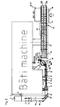
- In Fig. 1 ist die Längsseite einer erfindungsgemäßen Anlage in Seitenansicht dargestellt. An ihrer linken Stirnseite 1 ist auf einer Achse 2 drehbar - gegebenenfalls auch angetrieben - eine Doppelrolle 3 (s. a. Fig. 2 und 3) eines Folienbandes 4 angeordnet. Durch diese stirnseitige Anordnung in der Anlage wird Platz in und auf der Längsseite eingespart. Ein Trennmesser 5 schneidet die Doppelbahn 3 des Folienbandes 4 in zwei Einzelbahnen 6a und 6b auf. Jede Einzelbahn 6a, 6b wird durch eine Wendestange 7a, 7b, gegebenenfalls mit geführten Rollen, um 90° auf die Längsseite der Anlage umgelenkt. Die Umlenkung erfolgt so, dass die Einzelbahnen 6a, 6b - wie in Fig. 1 dargestellt - in zwei übereinander angeordneten Ebenen weitergeführt werden. Zu jeder Einzelbahn 6a, 6b sind jeweils eine Formglocke 8, ein Schweißkopf 9 sowie Press- und Kühleinrichtungen 10 vorgesehen, durch die die Verformung zu einem Rohrkörper 11 (Endlosrohren 11a, 11b) erfolgt, wobei hier auch das Anbringen einer hier überlappenden Seitenlängsnaht, z. B. durch Verschweißen erfolgen kann.
- Das Folienband 4 kann bereits Druck- oder Schriftbilder (nicht dargestellt) aufweisen und auch als Drei- oder Mehrfachband gestaltet sein, wobei dann weitere Trennmesser 5 und weitere Ebenen zur Herstellung der jeweils notwendigen Anzahl von Endlosrohren vorzusehen wären.
- Entsprechend der gewünschten Länge der Rohrkörper 11 bzw. eines Druckbildes werden durch Querschneider 12a, 12b, die z. B. eine Passersteuerung aufweisen, die Endlosrohre 11a, 11b in Rohrkörperabschnitte 13a, 13b mit einer jeweils gewünschten Länge abgetrennt. Ein Umsetzgerät 14 mit Saugprismen 15, die um 45° gekröpft sein können, übernimmt im Taktbetrieb jeweils zwei Rohrkörperabschnitte 13a, 13b bis insgesamt sechs Rohrkörperabschnitte 13a, 13b zu einer "Transfergruppe" zusammengestellt sind.
- Anschließend führt das Umsetzgerät 14 die "Transfergruppe" aus sechs Rohrkörperabschnitten 13a, 13b in eine um 90° gewendete Übernahmeposition 16, wo sie von einem horizontal beweglichen Vakuumaufschiebehalter 17 übernommen werden, d. h., es werden hierbei jeweils sechs Rohrkörperabschnitte 13a, 13b übergeben. Das Umsetzgerät 14 besteht aus zwei unabhängig voneinander arbeitenden Einzelumsetzbändern 18a und 18b mit jeweils sechs Saugprismen 15a, 15b. Diese Einzelumsetzbänder 18 sind so gesteuert und angetrieben, dass ein getaktetes Aufnehmen von je zwei Rohrkörperabschnitten 13a, 13b, im vorliegenden Fall im Takt 450/2 = 225/Minute, und ein ebenso getaktetes Abgeben, hier im Takt 450/6 = 75/Minute, bei jeweils sechs Rohrkörperabschnitten 13a, 13b gewährleistet wird, bzw. möglich ist.
Diese beiden Systeme arbeiten mit einer 180° Phasenverschiebung im Wechsel nach jeder Arbeitsseite. - Jeder Aufschiebehalter 17 führt eine lineare Auf- und Abbewegung aus, um z. B. die sechs Rohrkörperabschnitte 13a, 13b aus der Übernahmeposition 16 des Umsetzgerätes 14 in eine Aufschiebeposition 16' deckungsgleich (koaxial) zu Dornen 19 eines Drehtellers 20 zu bringen. Hierbei werden die jeweils sechs Rohrkörperabschnitte 13a, 13b gleichzeitig gemeinsam durch nicht dargestellte Mittel, z. B. Aufschiebestösseln auf die Dorne 19 aufgeschoben.
- Der Drehteller 20 ist derart gestaltet, dass jeweils sechs Dorne 19 in einem Schritt bzw. Takt nacheinander, beispielsweise acht, Stationen A- H (s. Fig. 1) zugestellt werden können. Durch den Drehteller 20 werden die Dorne 19 in einem Schritt nacheinander den einzelnen Stationen A - H mit Vorrichtungen zur Zusammenstellung von hier sechs vollständigen Tuben zugestellt. An den Stationen A - H werden alle jeweiligen Dorne 19 mit den notwendigen Komponenten versorgt bzw. von zugeführten Werkzeugen beaufschlagt.
- Bei dem dargestellten Ausführungsbeispiel werden bei der Station A gleichzeitig sechs Schulterstücke 21 mit Gewindehals auf die freien Ende der Dorne 19 aufgesetzt, bei Station B werden mittels Vakuum durch den Aufschiebehalter 17 sechs Rohrkörperabschnitte 13a, 13b über die Schulterstücke 21 hinweg auf die Dorne 19 aufgeschoben, d. h. auch gegeneinander positioniert, in der Station C werden die Tubenschultern 21 vorgeheizt, die in Position D mit dem Rohrkörperabschnitten 13a, 13b mittels HF-Induktionserwärmung verschweißt werden, in der Station E können Originalitätssicherungsmembranen (nicht dargestellt) auf die Entnahmeöffnung in den Schulterstücken 21 aufgesiegelt werden, wobei diese Station E auch beispielsweise zur Kühlung der verschweißten Schulterstücke 21 verwendet werden kann, in der Station F können Tubenverschlüsse 22 aufgeschraubt werden, die dann in Station G nachgeschraubt werden können, z. B. mit einem präzisen Drehmoment von 35 Ncm, wobei schließlich in der Station H die nun fertigen Tuben 23 von den Dornen 19 des Drehtellers 20 abgenommen bzw. entfernt werden, um z. B. auf ein kontinuierlich laufendes Auslaufband 24 zu gelangen.
- Das in Fig. 5 dargestellte Auslaufband 24 besteht aus zwei parallel nebeneinander angeordneten innenverzahnten Zahnriemen 25a und 25b, die mit Transportprismen 26 versehen sind. Die Transportprismen 26 bestehen aus zwei Teilprismen 26a, 26b, die gemeinsam auf den Zahnriemen 25a, 25b befestigt sind, die als Transportbänder dienen. Jeder der beiden Zahnriemen 25a, 25b ist durch eine verzahnte Antriebsriemenscheibe 27a bzw. 27b und eine frei gelagerte Umlenkriemenscheibe (nicht dargestellt) gespannt und geführt. Hierbei sind die Antriebsriemenscheiben 27a und 27b auf einer gemeinsamen Antriebswelle 28 angeordnet und durch eine Verstelleinrichtung 29 in ihrer relativen Winkel- bzw. Phasenlage gegeneinander verstellbar auf der Antriebswelle 28 angeordnet. Durch die Verstellung der Winkellage der Antriebsscheiben wird eine lineare Verschiebung der beiden Zahnriemen 25a, 25b bewirkt, wodurch gleichzeitig sämtliche Transportprismen 26 auf sehr einfache und zeitsparende Weise den jeweiligen frei gewählten Tubendurchmessern optimal anpassbar sind. Hierdurch ist die geometrische Achse aller Tuben 23 für alle Tubendurchmesser sehr einfach und immer auf der gleichen Höhe einstellbar. Die Anordnung der Transportprismen 26 entspricht im vorliegenden Beispiel dem Teilungsabstand der Dorne 19 und beträgt 95 mm. Da hier sechs Dorne 19 vorgesehen sind erfolgt die Zuführung der Schulterstücke 21 und der Tubenverschlüsse 22 ebenfalls sechsfach, wobei auch z. B. vier, acht oder andere Anzahlen möglich sind.
- Auf dem in Fig. 4 dargestellten Auslaufband 24 können die Tuben 23 beispielsweise vier verschiedene Kontroll- und Ausschleuszonen durchlaufen, die sich z. B. im Bereich 30 entlang eines Teils oder der ganzen Länge des Obertrums des Auslaufbandes 24 befinden. Die vier Kontroll- und Ausschleuszonen können beispielsweise sein: eine erste Kontrolle auf Tuben ohne Verschluss; eine zweite Kontrolle als statistische Qualitätskontrolle; eine dritte Kontrolle auf unbrauchbare Ausschußtuben und eine vierte Kontrolle auf gute (verwendbare) Tuben. In der statistischen Qualitätskontrolle können in zeitlich frei wählbaren Intervallen automatisch Mustertuben ausgeschleust werden. Ausschusstuben bzw. fehterbehaftete Tuben 23' können am Ende des Auslaufbandes 24 ausgeworfen werden.
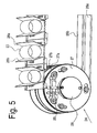
- Am Ende des linearen Bereiches des Auslaufbandes 24 ist eine Sammeleinrichtung 31 mit z. B. sechs rotierenden Ansaugprismen 32 angeordnet, durch die gute (einwandfreie) Tuben 23 lückenlos, z. B. in Trays 34, aufgenommen werden können.
- Durch dieses vorgestellte Vierwegesystem mit dem selektiven Auswerfen unterschiedlich verwendbarer Tuben 23 an örtlich verschiedenen Stellen entlang des Auslaufbandes 24 ist es möglich, jeweils in Abhängigkeit der jeweiligen Qualitätseigenschaften bzw. der Art der Tuben 23 - ohne jegliches manuelles Eingreifen - die geeigneten Tuben 23 von den ungeeigneten Tuben 23' voneinander zu trennen.
- Die sechs Saugprismen 32 im Bereich 31 (Fig. 4) sind im gleichen Teilungsabstand wie die reinen Transportprismen 26 angeordnet. Durch eine individuelle Ansteuerung der Drehbewegung der sechs Saugprismen 32 können somit alle auf dem Auslaufband 24 herangeführten Tuben 23 nach frei wählbaren und einstellbaren Kriterien lückenlos gesammelt werden, z. B. so, dass nur absolut einwandfreie Tuben 23 erfasst werden.
- Eine Möglichkeit der Steuerung hierzu besteht über das Erfassen der beim Durchlaufen der verschiedenen Arbeitsstationen A bis H tatsächlich vorhandenen jeweiligen Prozessparameter oder Produktionsparameter, bezogen auf eine Tube 23, auf die dann jede auf dem Auslaufband 24 herantransportierte Tube 23 überprüft wird. Das Ergebnis kann der jeweiligen überprüften Tube 23 auch genau zugeordnet werden. Zur Steuerung dient somit das zu jeder Tube 23 hergestellte temporäre "History-File" (Vergangenheitsdatei), der alle wesentlichen Produktionsparameter, z. B. in einem Produktionsdatensatz, zugeordnet sind und fehlerhafte Tuben 23', gemäß den eingestellten Ausscheidungskriterien, an einer geeigneten Stelle aussortiert werden bzw. erfasst werden. Bei der Erfassung kann festgestellt werden, ob z. B. die Schweißtemperatur oder das Vorheizen auf dem gewünschten Sollwert erfolgte oder nicht ausreichend war. War der vorgegebene Sollwert nicht erreicht und sind dadurch fehlerhafte Tuben 23' hergestellt worden, müssen sie ausgeschieden werden. Es kann auch ein fehlender Verschluss 22 auf einer Tube 23 erkannt werden. Fehlerhafte oder nicht komplette Tuben 23 werden an einer definierten Stelle entfernt. Durch die geschilderte Steuerung wird gewährleistet, dass nur absolut einwandfreie Tuben 23 der Sammeleinrichtung 31 zugeführt werden.
- Die in Fig. 4 dargestellte Tubenübergabe von den Dornen 19 des Drehtellers 20 auf das kontinuierlich laufende Auslaufband 24 erfolgt in einem Ablegebereich 33 bzw. einer Ablegestation für jeweils alle sechs - eine Einheit bildende - Dorne 19 des Drehtellers 20. Sie können z. B. durch nicht dargestellte Abnahmezangen von den Dornen 19 abgezogen und gegebenenfalls mittels drehbarer Halter 32' in Transportprismen 26 abgelegt werden. Eine der Vorschubbewegung des Auslaufbandes 24 angepasste Drehbewegung der Halter 32' sorgt für eine vollständige reibungslose Übergabe, wobei jeweils alle Tuben 23 einer Einheit (hier sechs) entladen werden und auf das Auslaufband 24 gelangen.
- Die Selektion nach der Qualität der hergestellten Tuben 23 entsprechend der oben beschriebenen Kriterien erfolgt erst in der nachfolgende Zone 30 des Auslaufbandes 24 (siehe Fig. 4).
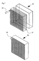
- In der dieser nachfolgenden Zone 30 werden dann nur die einwandfreien Tuben 23 mittels der Sammeleinrichtung 31 jeweils als Einheit- hier sechs Tuben 23- gesammelt und erst nach dem Erreichen einer vollständigen Einheit, d. h. hier von sechs einwandfreien Tuben, gemeinsam lückenlos in spezielle Trays 34 übergeben.
- Die Sammeleinrichtung 31 weist sechs Stationen mit sechs drehbaren Haltern 32A, 32B, 32C, 32D, 32E und 32F mit Saugprismen auf. In Fig. 6 ist vereinfacht nur ein einziger Halter 32A mit Saugprisma dargestellt. Alle Halter 32 mit Saugprismen sind parallel und oberhalb des Auslaufbandes 24 angeordnet. In der jeweiligen Übergabe- bzw. Übernahmeposition bezogen auf das Auslaufband 24 weist jeder Halter 32, ein Saugprisma mit einer Kavität auf, die in der jeweiligen Rast- bzw. Ruhestellung (s. Fig. 6a) nach oben gerichtet ist. Nähert sich auf dem Sammelband 24 im Transportprisma 26A eine als brauchbar erkannte Tube 23 mit geradliniger Geschwindigkeit V1 der Station 32A erfolgt eine Drehung des Saugprismas des Halters 32A mit Umfangsgeschwindigkeit U1 und durch die durch die Bohrungen 35 aufgebrachte Saugkraft wird die Tube 23 mittels des Saugprismas des Halters 32A erfasst. Um eine einwandfreie Übernahme der Tube 23 sicherzustellen, wird die Umfangsgeschwindigkeit U1 möglichst eng an die geradlinige Geschwindigkeit V1 angepasst oder ihr gleich gewählt. Die Bohrungen 35 im Halter 32, die in seiner Kavität münden, sind an eine nicht dargestellte Saugquelle angeschlossen, wodurch die Tube 23 aus dem Transportprisma 26A entnommen wird.
- Im in Fig. 4 als Ausführungsbeispiel dargestellten Momentanzustand ist auch die nachfolgende gute = einwandfreie Tube 23 vom Transportprisma 26B an der Station 32B durch den Halter 32B entnommen worden.
- Sofern entsprechend der vorgenommenen Selektion eine sich als unbrauchbar erkannte Tube 23' im Transportprisma 26C dem nächsten freien Halter 32C mit Saugprisma nähert, dreht sich der Halter 32C nicht und die fehlerhafte Tube 23' verbleibt auf dem Auslaufband 24 und wird an dessen Ende abgeworfen bzw. entsorgt.
- Ist die nächste auf dem Auslaufband 24 ankommende Tube 23 im Transportprisma 26D wieder in Ordnung, dreht sich der Halter 32C mit Saugprisma und erfasst die Tube 23 und dreht sie nach oben, so dass in der Position 32C eine dritte einwandfreie Tube 23 vorliegt. Das gleiche erfolgt bis eine vierte einwandfreie Tube 23 aus dem Transportprisma 26A' in der nachfolgenden Position 32D, dann eine fünfte aus 26B' in 32E und schließlich eine sechste aus 26D' in 32F liegt, d. h. bis sechs einwandfreie Tuben 23 in allen Stationen 32A - 32F der Sammeleinrichtung 31 vorliegen. Die unbesetzt dargestellten Transportprismen 26E und 26F fahren unter der Sammeleinrichtung 31 durch, ohne dass einer der drehbaren Halter 32 aktiviert wird. Sodann werden alle sechs in den Stationen 32A - 32F angeordneten Tuben 23 gemeinsam und damit lückenlos einem Tray 34 übergeben, z. B. mittels eines gemeinsamen - nur angedeuteten - Schiebers 36 überführt. Entsprechend der sukzessiven Beladung wird dann das Tray 34 zur Aufnahme der nächsten Einheit von einwandfreien Tuben 23 verschoben. Hierdurch ist gewährleistet, dass automatisch nur als einwandfrei erkannte Tuben 23 im Tray 34 landen.
- Die Sammeleinrichtung 31 kann auch zum "Lückenauffüllen" in einem beliebigen Tubentransportsystem z.B. einem Tubenspeicher dienen.
- Das gefüllte Tray 34 wird als solches z. B. über Transportbänder einer beliebigen Befüllstation zugeführt, wo die im Tray 34 angeordneten Tuben 23 mit einem Produkt befüllt werden. Die Befüllung kann auch erst dann erfolgen, wenn die Tuben 23 bereits dem Tray 34 entnommen sind. Es ist offensichtlich, dass durch die Erfindung die Anzahl der notwendigen Operationen sich deutlich verringern lassen und dass sie sich auch automatisieren lassen, so dass Handarbeit nicht notwendig ist.
Claims (8)
- Anlage zum Herstellen und Verpacken von aus einem Rohrkörper (13a, b) aus mindestens einer Kunststofffolie und einem einends verbundenen Schulterstück (21) mit Gewindehals und aufgebrachter Verschlusskappe (22) bestehenden Tuben (23), die über ein Transportband einer Verpackungsstation zugeführt werden, wo sie zu größeren Einheiten verpackt werden, dadurch gekennzeichnet, dass das Folienband (4) ein Zwei- oder Mehrfachband ist, das durch ein oder mehrere Trennmesser (5) in Einzelbahnen (6a, b) geschnitten wird, die jeweils in parallelen Ebenen zu Endlosrohren (11a, b) verschweißt und durch Querschneider (12a, b) auf die gewünschte Rohrlänge abgelängt werden, wonach jeweils die parallel hergestellten abgelängten Rohrkörper (13a, b) zu einer größeren Transfergruppe zusammengestellt und gemeinsam auf einen eine entsprechende Anzahl von Dornen (19) aufweisenden Drehteller (20) übergeben werden, durch den sie gemeinsam und schrittweise Stationen (A bis H) zum Aufbringen des Schulterstücks (21) mit Gewindehals und der Verschlusskappe (22) zugeführt werden, wonach die fertigen Tuben (23) auf einem Auslaufband (24) abgelegt werden, das mindestens aus zwei parallel nebeneinander liegenden Zahnriemen (25a und 25b) mit Transportprismen (26a und 26b) besteht, deren Teilung der der Dorne (19) auf dem Drehteller (20) entspricht, und Kontrollzonen zur Überprüfung der Tuben (23) zugeführt und die einwandfreien. Tuben (23), mittels dem Abstand der Transportprismen (26) entsprechenden, drehbaren Ansaugprismen (32) vom Auslaufband (24) aufgenommen und lückenlos einem Tray (34) zugeführt werden.
- Anlage nach Anspruch 1, dadurch gekennzeichnet, dass die Rolle (3) mit der Laminatfolie senkrecht zu den herzustellenden Rohrkörpern (13a, b) angeordnet und deren Einzelbahnen (6a, b) zur Bildung der Rohrkörper (13a, b) jeweils um 90° umgelenkt sind.
- Anlage nach Anspruch 1 und 2, dadurch gekennzeichnet, dass die Einzelbahnen (6a, b) übereinander zu Endlosrohren (11a, b) verschweißbar sind.
- Anlage nach Anspruch 1 und 2, dadurch gekennzeichnet, dass die Einzelbahnen (6a, b) nebeneinander zu Endlosrohren (11a, b) verschweißbar sind.
- Anlage nach einem der Ansprüche 1 bis 4, dadurch gekennzeichnet, dass die nicht verwendbaren Tuben (23') durch das Auslaufband (24) aus der Anlage austragbar sind.
- Anlage nach einem der Ansprüche 1 bis 5, dadurch gekennzeichnet, dass das Auslaufband (24) aus zwei gegeneinander phasenverschiebbar angeordneten Zahnriemen (25a und 25b) mit Transportprismen (26a und 26b) besteht.
- Anlage nach einem der Ansprüche 1 bis 6, dadurch gekennzeichnet, dass jedes Tray (34) einen an die Durchmesser der Tuben (23) angepassten Rastereinsatz aufweist.
- Anlage nach einem der Ansprüche 1 bis 7, dadurch gekennzeichnet, dass eine Sammeleinrichtung (31) mit mehreren Stationen vorgesehen ist.
Applications Claiming Priority (3)
| Application Number | Priority Date | Filing Date | Title |
|---|---|---|---|
| DE10237839A DE10237839B3 (de) | 2002-08-19 | 2002-08-19 | Anlage zum Herstellen und Verpacken von Tuben |
| DE10237839 | 2002-08-19 | ||
| PCT/EP2003/008481 WO2004026567A1 (de) | 2002-08-19 | 2003-07-31 | Anlage zum herstellen und verpacken von tuben |
Publications (2)
| Publication Number | Publication Date |
|---|---|
| EP1531982A1 EP1531982A1 (de) | 2005-05-25 |
| EP1531982B1 true EP1531982B1 (de) | 2006-05-10 |
Family
ID=29762134
Family Applications (1)
| Application Number | Title | Priority Date | Filing Date |
|---|---|---|---|
| EP03747870A Expired - Lifetime EP1531982B1 (de) | 2002-08-19 | 2003-07-31 | Anlage zum herstellen und verpacken von tuben |
Country Status (16)
| Country | Link |
|---|---|
| US (1) | US7448187B2 (de) |
| EP (1) | EP1531982B1 (de) |
| JP (1) | JP2005536381A (de) |
| KR (1) | KR100989870B1 (de) |
| CN (1) | CN100546817C (de) |
| AT (1) | ATE325702T1 (de) |
| AU (1) | AU2003266959B2 (de) |
| BG (1) | BG109016A (de) |
| BR (1) | BR0313601B1 (de) |
| DE (2) | DE10237839B3 (de) |
| ES (1) | ES2263995T3 (de) |
| HU (1) | HUP0500586A2 (de) |
| MX (1) | MXPA05001995A (de) |
| PL (1) | PL208411B1 (de) |
| RU (1) | RU2323828C2 (de) |
| WO (1) | WO2004026567A1 (de) |
Families Citing this family (17)
| Publication number | Priority date | Publication date | Assignee | Title |
|---|---|---|---|---|
| EP1862284A1 (de) * | 2006-06-02 | 2007-12-05 | Aisapack Holding SA | Vorrichtung zum Übertragen rohrförmiger Körper |
| US20090313943A1 (en) * | 2008-06-19 | 2009-12-24 | Haumiller Engineering Company | Apparatus and method for inserting valve assemblies into containers |
| EP2821197A1 (de) | 2013-07-03 | 2015-01-07 | Aisapack Holding SA | Indexierende Schweißvorrichtung für Rohr |
| FR3035865B1 (fr) * | 2015-05-07 | 2019-09-06 | C.E.R.M.E.X. Constructions Etudes Et Recherches De Materiels Pour L'emballage D'expedition | Alimentation controlee pour solution de conditionnement par lots |
| FR3035864B1 (fr) * | 2015-05-07 | 2019-10-04 | C.E.R.M.E.X. Constructions Etudes Et Recherches De Materiels Pour L'emballage D'expedition | Architecture de conditionnement par lots avec alimentation controlee |
| CN108248060A (zh) * | 2018-01-10 | 2018-07-06 | 茂联橡胶制品(深圳)有限公司 | 一种机械手系统以及带有该系统的五金帽件生产线 |
| US11541609B2 (en) * | 2018-07-03 | 2023-01-03 | Dukane Ias, Llc | System and method for simultaneous welding of plastic bags using a carrier film |
| US11548235B2 (en) | 2018-07-03 | 2023-01-10 | Dukane Ias, Llc | Laser welding system and method using machined clamping tool |
| CN109131981B (zh) * | 2018-09-30 | 2020-12-15 | 温州市剑峰文具有限公司 | 一种全自动铅笔芯灌装机的盒体灌装组装系统 |
| CN110640361B (zh) * | 2019-10-12 | 2021-07-20 | 山东舜博金属制品有限公司 | 一种双工位自动焊接机 |
| CN110641943B (zh) * | 2019-10-21 | 2021-06-15 | 远大可建科技有限公司 | 一种管体输送线及其输送方法 |
| CN111846824B (zh) * | 2020-06-29 | 2025-07-15 | 浙江正雅齿科股份有限公司 | 压膜系统 |
| CN111907831A (zh) * | 2020-08-20 | 2020-11-10 | 佛山市源达科技有限公司 | 一种玻璃胶瓶自动计数装袋机 |
| CN112678222B (zh) * | 2020-12-14 | 2022-11-08 | 季亚君 | 注射器装载机 |
| CN114291343B (zh) * | 2021-11-25 | 2023-03-17 | 芜湖海利特汽车空调配件有限公司 | 一种汽车空调系统冷凝管生产用装箱装置及使用方法 |
| CN115782269A (zh) * | 2022-11-05 | 2023-03-14 | 绍兴上虞中科软管塑业有限公司 | 膏液软管的制备方法及其生产线 |
| JP2024077264A (ja) * | 2022-11-28 | 2024-06-07 | シブヤパッケージングシステム株式会社 | 容器充填シール装置 |
Family Cites Families (27)
| Publication number | Priority date | Publication date | Assignee | Title |
|---|---|---|---|---|
| US2923975A (en) * | 1960-02-09 | Method for moulding a tube of plastic material | ||
| DE110833C (de) * | 1900-01-01 | |||
| US2383230A (en) * | 1941-04-16 | 1945-08-21 | Voke Carl Edward | Manufacture of collapsible tubes and the like |
| US3047910A (en) * | 1959-11-24 | 1962-08-07 | Plastomer Dev Corp | Method of making thermoplastic tubular container |
| GB1100423A (en) * | 1964-02-24 | 1968-01-24 | American Can Co | Method and device for treating a smooth plastic sheet surface to reduce its coefficient of friction with respect to a smooth body surface |
| US3575769A (en) * | 1968-03-27 | 1971-04-20 | American Can Co | Tube side seaming method and apparatus |
| JPS5221425B1 (de) * | 1971-02-25 | 1977-06-10 | ||
| US3778321A (en) * | 1971-10-14 | 1973-12-11 | Victor Metal Products Corp | Apparatus for making rolled collapsible container having plastic outsert |
| US3764425A (en) * | 1972-01-10 | 1973-10-09 | Milprint Inc | Apparatus and method for the manufacture of tubular containers |
| US3896710A (en) * | 1973-09-14 | 1975-07-29 | Dart Ind Inc | Foldable tubular package apparatus |
| JPS6030538B2 (ja) * | 1974-05-31 | 1985-07-17 | 株式会社吉野工業所 | 合成樹脂製チユ−ブ自動加工機 |
| US3986636A (en) * | 1975-04-17 | 1976-10-19 | Hoppmann Corporation | High speed method for translating articles from in-line array to side by side array |
| US4079664A (en) * | 1976-04-14 | 1978-03-21 | Victor Metal Products Corporation | Collapsible container forming machine |
| DE2643089C3 (de) * | 1976-09-24 | 1983-04-21 | Automation Industrielle S.A., 1896 Vouvry | Vorrichtung zum Herstellen eines verformbaren Rohres |
| CH607695A5 (de) * | 1976-10-13 | 1978-10-13 | Karl Maegerle | |
| CH610543A5 (en) * | 1977-04-29 | 1979-04-30 | Victor Metal Products Corp | Machine for manufacturing deformable packaging tubes |
| JPS5443033A (en) | 1977-09-12 | 1979-04-05 | Ricoh Co Ltd | Paper detecting method |
| SE445031B (sv) * | 1984-10-02 | 1986-05-26 | Akerlund & Rausing Ab | Forpackningstub samt forfarande och anordning for tillverkning derav |
| DE3531663A1 (de) * | 1985-09-05 | 1987-03-12 | Altstaedter Verpack Vertrieb | Verfahren zur herstellung einer fluessigkeitspackung und vorrichtung zur durchfuehrung des verfahrens |
| ATE149012T1 (de) * | 1989-07-21 | 1997-03-15 | Maegerle Karl Lizenz | Vorrichtung und verfahren zur herstellung von rohrkörpern |
| DE4009661C1 (de) * | 1990-03-26 | 1991-03-07 | Aisa Automation Industrielle S.A., Vouvry, Ch | |
| US5310300A (en) * | 1992-02-03 | 1994-05-10 | R. A. Pearson Co. | Apparatus and method for packing containers onto a rack |
| US5621960A (en) * | 1994-04-15 | 1997-04-22 | Owens-Illinois Plastic Products Inc. | Method and apparatus for forming an assembly of a flexible tube and closure |
| JP2922800B2 (ja) * | 1994-11-07 | 1999-07-26 | 株式会社アイテック | チューブ入り練状物の製造方法 |
| DE19522169C2 (de) * | 1995-06-19 | 1997-05-28 | Automation Industrielle Sa | Verfahren zur Herstellung eines insbesondere mehrschichtigen Rohrkörpers mit mindestens einer Trennwand für eine Tube |
| US6047525A (en) * | 1998-11-25 | 2000-04-11 | Thatcher Tubes Llc | Plant for manufacturing and packing thermoplastic tubes |
| WO2002074523A1 (fr) * | 2001-03-19 | 2002-09-26 | Cebal S.A.S. | Atelier de fabrication de tubes souples en matiere plastique avec moulage de la tete sur la jupe effectuee par des outillages en mouvement continu |
-
2002
- 2002-08-19 DE DE10237839A patent/DE10237839B3/de not_active Expired - Fee Related
-
2003
- 2003-07-31 RU RU2005107712/12A patent/RU2323828C2/ru not_active IP Right Cessation
- 2003-07-31 AU AU2003266959A patent/AU2003266959B2/en not_active Ceased
- 2003-07-31 US US10/524,943 patent/US7448187B2/en not_active Expired - Fee Related
- 2003-07-31 EP EP03747870A patent/EP1531982B1/de not_active Expired - Lifetime
- 2003-07-31 PL PL373172A patent/PL208411B1/pl not_active IP Right Cessation
- 2003-07-31 HU HU0500586A patent/HUP0500586A2/hu unknown
- 2003-07-31 MX MXPA05001995A patent/MXPA05001995A/es active IP Right Grant
- 2003-07-31 JP JP2004536919A patent/JP2005536381A/ja active Pending
- 2003-07-31 CN CNB038187620A patent/CN100546817C/zh not_active Expired - Fee Related
- 2003-07-31 BR BRPI0313601-9B1A patent/BR0313601B1/pt not_active IP Right Cessation
- 2003-07-31 KR KR1020057002562A patent/KR100989870B1/ko not_active Expired - Fee Related
- 2003-07-31 AT AT03747870T patent/ATE325702T1/de not_active IP Right Cessation
- 2003-07-31 DE DE50303307T patent/DE50303307D1/de not_active Expired - Lifetime
- 2003-07-31 ES ES03747870T patent/ES2263995T3/es not_active Expired - Lifetime
- 2003-07-31 WO PCT/EP2003/008481 patent/WO2004026567A1/de not_active Ceased
-
2005
- 2005-01-17 BG BG109016A patent/BG109016A/xx unknown
Also Published As
| Publication number | Publication date |
|---|---|
| ATE325702T1 (de) | 2006-06-15 |
| JP2005536381A (ja) | 2005-12-02 |
| DE50303307D1 (de) | 2006-06-14 |
| MXPA05001995A (es) | 2005-06-03 |
| CN1675053A (zh) | 2005-09-28 |
| BR0313601A (pt) | 2005-06-21 |
| AU2003266959B2 (en) | 2009-01-08 |
| KR20050056988A (ko) | 2005-06-16 |
| WO2004026567A1 (de) | 2004-04-01 |
| PL208411B1 (pl) | 2011-04-29 |
| RU2323828C2 (ru) | 2008-05-10 |
| HK1082466A1 (zh) | 2006-06-09 |
| US7448187B2 (en) | 2008-11-11 |
| DE10237839B3 (de) | 2004-01-22 |
| BG109016A (en) | 2005-12-30 |
| US20060105077A1 (en) | 2006-05-18 |
| BR0313601B1 (pt) | 2013-12-17 |
| PL373172A1 (en) | 2005-08-22 |
| AU2003266959A1 (en) | 2004-04-08 |
| HUP0500586A2 (hu) | 2005-10-28 |
| ES2263995T3 (es) | 2006-12-16 |
| RU2005107712A (ru) | 2005-08-10 |
| KR100989870B1 (ko) | 2010-12-22 |
| CN100546817C (zh) | 2009-10-07 |
| EP1531982A1 (de) | 2005-05-25 |
Similar Documents
| Publication | Publication Date | Title |
|---|---|---|
| EP1531982B1 (de) | Anlage zum herstellen und verpacken von tuben | |
| EP0386524B1 (de) | Vorrichtung (Verpackungsmaschine) zum Verpacken von Gegenständen unterschiedlicher Grösse | |
| EP4301562B1 (de) | Nahrungsmittelverarbeitungsanlage | |
| EP2763918B1 (de) | Verfahren und vorrichtung zum fördern von streifenförmigen oder plattenförmigen produkten | |
| EP2502509B1 (de) | Schälautomat für langgestrecktes Schälgut und Schälverfahren | |
| EP2481564B1 (de) | Verfahren zur Herstellung von Säcken, bei welchem Stapel von Säcken oder Sackhalbzeugen von einer ersten Maschine zu einer zweiten Maschine transportiert werden, sowie System, das eine erste Maschine und eine Transport- und Speichervorrichtung enthält | |
| CH717313A2 (de) | Vorrichtung zur Entnahme eines ausgestanzten Teils aus einer Stanzvorrichtung. | |
| EP2481566B1 (de) | Verfahren und System zum Abarbeiten von Aufträgen zur Herstellung von Säcken | |
| EP1780000B1 (de) | Vorrichtung und Verfahren zur Herstellung von Kunststoffbeuteln | |
| DE102016002244B4 (de) | Bearbeitungsvorrichtung, Anlage und Bearbeitungsverfahren für Behälter unterschiedlicher Typen | |
| EP1293453B1 (de) | Vorrichtung zur Herstellung palettierfähiger Lagen | |
| WO2023169940A1 (de) | Vorrichtung und verfahren zum handhaben von packungen für produkte der zigarettenindustrie | |
| EP2481565B1 (de) | Verfahren und ein System zum Abarbeiten zumindest zweier aufeinander folgender Aufträge zur Herstellung von Säcken | |
| EP4490050A1 (de) | VORRICHTUNG ZUM SIEGELN UND/ODER SCHRUMPFEN VON AUßENUMHÜLLUNGEN VON PACKUNGEN | |
| EP3441315A1 (de) | Verfahren und verpackungssystem zum herstellen von gebinden | |
| EP1357037A1 (de) | Einrichtung und Verfahren zum Zuführen von Packstoffmaterial | |
| DE60011830T2 (de) | Fördervorrichtung zum Bilden und Fördern von Gruppen von Gegenständen | |
| EP4613116A2 (de) | Innerliner-wickel-trommel mit packtrommel | |
| DE102021133836A1 (de) | Vorrichtung und Verfahren zum Bereitstellen flächiger Zuschnitte zur jeweiligen Verpackung mehrerer Artikel | |
| DE19860863A1 (de) | Verfahren und Einrichtung zur Verpackung von Einzelstücken zu mehrere Einzelstücke enthaltende Stangen | |
| CH418951A (de) | Verfahren und Maschine zum Herstellen, Füllen und Schliessen von Packungen | |
| DE2401448A1 (de) | Anlage zum verpacken von abfuellbaren produkten | |
| HK1082466B (en) | Installation for producing and packing tubes |
Legal Events
| Date | Code | Title | Description |
|---|---|---|---|
| PUAI | Public reference made under article 153(3) epc to a published international application that has entered the european phase |
Free format text: ORIGINAL CODE: 0009012 |
|
| 17P | Request for examination filed |
Effective date: 20050216 |
|
| AK | Designated contracting states |
Kind code of ref document: A1 Designated state(s): AT BE BG CH CY CZ DE DK EE ES FI FR GB GR HU IE IT LI LU MC NL PT RO SE SI SK TR |
|
| AX | Request for extension of the european patent |
Extension state: AL LT LV MK |
|
| GRAP | Despatch of communication of intention to grant a patent |
Free format text: ORIGINAL CODE: EPIDOSNIGR1 |
|
| DAX | Request for extension of the european patent (deleted) | ||
| GRAS | Grant fee paid |
Free format text: ORIGINAL CODE: EPIDOSNIGR3 |
|
| GRAA | (expected) grant |
Free format text: ORIGINAL CODE: 0009210 |
|
| AK | Designated contracting states |
Kind code of ref document: B1 Designated state(s): AT BE BG CH CY CZ DE DK EE ES FI FR GB GR HU IE IT LI LU MC NL PT RO SE SI SK TR |
|
| PG25 | Lapsed in a contracting state [announced via postgrant information from national office to epo] |
Ref country code: SI Free format text: LAPSE BECAUSE OF FAILURE TO SUBMIT A TRANSLATION OF THE DESCRIPTION OR TO PAY THE FEE WITHIN THE PRESCRIBED TIME-LIMIT Effective date: 20060510 Ref country code: FI Free format text: LAPSE BECAUSE OF FAILURE TO SUBMIT A TRANSLATION OF THE DESCRIPTION OR TO PAY THE FEE WITHIN THE PRESCRIBED TIME-LIMIT Effective date: 20060510 Ref country code: NL Free format text: LAPSE BECAUSE OF FAILURE TO SUBMIT A TRANSLATION OF THE DESCRIPTION OR TO PAY THE FEE WITHIN THE PRESCRIBED TIME-LIMIT Effective date: 20060510 Ref country code: IE Free format text: LAPSE BECAUSE OF FAILURE TO SUBMIT A TRANSLATION OF THE DESCRIPTION OR TO PAY THE FEE WITHIN THE PRESCRIBED TIME-LIMIT Effective date: 20060510 |
|
| REG | Reference to a national code |
Ref country code: GB Ref legal event code: FG4D Free format text: NOT ENGLISH |
|
| REG | Reference to a national code |
Ref country code: CH Ref legal event code: EP |
|
| REF | Corresponds to: |
Ref document number: 50303307 Country of ref document: DE Date of ref document: 20060614 Kind code of ref document: P |
|
| REG | Reference to a national code |
Ref country code: IE Ref legal event code: FG4D Free format text: LANGUAGE OF EP DOCUMENT: GERMAN |
|
| REG | Reference to a national code |
Ref country code: RO Ref legal event code: EPE |
|
| PG25 | Lapsed in a contracting state [announced via postgrant information from national office to epo] |
Ref country code: BE Free format text: LAPSE BECAUSE OF NON-PAYMENT OF DUE FEES Effective date: 20060731 Ref country code: MC Free format text: LAPSE BECAUSE OF NON-PAYMENT OF DUE FEES Effective date: 20060731 |
|
| PG25 | Lapsed in a contracting state [announced via postgrant information from national office to epo] |
Ref country code: DK Free format text: LAPSE BECAUSE OF FAILURE TO SUBMIT A TRANSLATION OF THE DESCRIPTION OR TO PAY THE FEE WITHIN THE PRESCRIBED TIME-LIMIT Effective date: 20060810 |
|
| REG | Reference to a national code |
Ref country code: SE Ref legal event code: TRGR |
|
| REG | Reference to a national code |
Ref country code: CH Ref legal event code: NV Representative=s name: BRAUNPAT BRAUN EDER AG |
|
| PG25 | Lapsed in a contracting state [announced via postgrant information from national office to epo] |
Ref country code: PT Free format text: LAPSE BECAUSE OF FAILURE TO SUBMIT A TRANSLATION OF THE DESCRIPTION OR TO PAY THE FEE WITHIN THE PRESCRIBED TIME-LIMIT Effective date: 20061010 |
|
| GBT | Gb: translation of ep patent filed (gb section 77(6)(a)/1977) |
Effective date: 20060918 |
|
| REG | Reference to a national code |
Ref country code: HU Ref legal event code: AG4A Ref document number: E000668 Country of ref document: HU |
|
| NLV1 | Nl: lapsed or annulled due to failure to fulfill the requirements of art. 29p and 29m of the patents act | ||
| REG | Reference to a national code |
Ref country code: ES Ref legal event code: FG2A Ref document number: 2263995 Country of ref document: ES Kind code of ref document: T3 |
|
| ET | Fr: translation filed | ||
| REG | Reference to a national code |
Ref country code: IE Ref legal event code: FD4D |
|
| PLBE | No opposition filed within time limit |
Free format text: ORIGINAL CODE: 0009261 |
|
| STAA | Information on the status of an ep patent application or granted ep patent |
Free format text: STATUS: NO OPPOSITION FILED WITHIN TIME LIMIT |
|
| 26N | No opposition filed |
Effective date: 20070213 |
|
| PG25 | Lapsed in a contracting state [announced via postgrant information from national office to epo] |
Ref country code: AT Free format text: LAPSE BECAUSE OF NON-PAYMENT OF DUE FEES Effective date: 20060731 |
|
| BERE | Be: lapsed |
Owner name: AISA AUTOMATION INDUSTRIELLE SA Effective date: 20060731 |
|
| PG25 | Lapsed in a contracting state [announced via postgrant information from national office to epo] |
Ref country code: GR Free format text: LAPSE BECAUSE OF FAILURE TO SUBMIT A TRANSLATION OF THE DESCRIPTION OR TO PAY THE FEE WITHIN THE PRESCRIBED TIME-LIMIT Effective date: 20060811 |
|
| PG25 | Lapsed in a contracting state [announced via postgrant information from national office to epo] |
Ref country code: EE Free format text: LAPSE BECAUSE OF FAILURE TO SUBMIT A TRANSLATION OF THE DESCRIPTION OR TO PAY THE FEE WITHIN THE PRESCRIBED TIME-LIMIT Effective date: 20060510 |
|
| PG25 | Lapsed in a contracting state [announced via postgrant information from national office to epo] |
Ref country code: LU Free format text: LAPSE BECAUSE OF NON-PAYMENT OF DUE FEES Effective date: 20060731 |
|
| PGFP | Annual fee paid to national office [announced via postgrant information from national office to epo] |
Ref country code: ES Payment date: 20080723 Year of fee payment: 6 |
|
| PG25 | Lapsed in a contracting state [announced via postgrant information from national office to epo] |
Ref country code: CY Free format text: LAPSE BECAUSE OF FAILURE TO SUBMIT A TRANSLATION OF THE DESCRIPTION OR TO PAY THE FEE WITHIN THE PRESCRIBED TIME-LIMIT Effective date: 20060510 |
|
| PGFP | Annual fee paid to national office [announced via postgrant information from national office to epo] |
Ref country code: CZ Payment date: 20080725 Year of fee payment: 6 Ref country code: RO Payment date: 20080728 Year of fee payment: 6 Ref country code: SK Payment date: 20080723 Year of fee payment: 6 |
|
| PGFP | Annual fee paid to national office [announced via postgrant information from national office to epo] |
Ref country code: TR Payment date: 20080722 Year of fee payment: 6 |
|
| PGFP | Annual fee paid to national office [announced via postgrant information from national office to epo] |
Ref country code: HU Payment date: 20080710 Year of fee payment: 6 |
|
| REG | Reference to a national code |
Ref country code: SK Ref legal event code: MM4A Ref document number: E 936 Country of ref document: SK Effective date: 20090731 |
|
| PG25 | Lapsed in a contracting state [announced via postgrant information from national office to epo] |
Ref country code: RO Free format text: LAPSE BECAUSE OF NON-PAYMENT OF DUE FEES Effective date: 20090731 Ref country code: CZ Free format text: LAPSE BECAUSE OF NON-PAYMENT OF DUE FEES Effective date: 20090731 Ref country code: HU Free format text: LAPSE BECAUSE OF NON-PAYMENT OF DUE FEES Effective date: 20090801 |
|
| PG25 | Lapsed in a contracting state [announced via postgrant information from national office to epo] |
Ref country code: SK Free format text: LAPSE BECAUSE OF NON-PAYMENT OF DUE FEES Effective date: 20090731 |
|
| REG | Reference to a national code |
Ref country code: ES Ref legal event code: FD2A Effective date: 20090801 |
|
| PG25 | Lapsed in a contracting state [announced via postgrant information from national office to epo] |
Ref country code: ES Free format text: LAPSE BECAUSE OF NON-PAYMENT OF DUE FEES Effective date: 20090801 |
|
| PG25 | Lapsed in a contracting state [announced via postgrant information from national office to epo] |
Ref country code: TR Free format text: LAPSE BECAUSE OF NON-PAYMENT OF DUE FEES Effective date: 20090731 |
|
| PGFP | Annual fee paid to national office [announced via postgrant information from national office to epo] |
Ref country code: SE Payment date: 20130723 Year of fee payment: 11 |
|
| REG | Reference to a national code |
Ref country code: DE Ref legal event code: R082 Ref document number: 50303307 Country of ref document: DE Representative=s name: KEILITZ & SOELLNER, PARTNERSCHAFT, DE |
|
| PGFP | Annual fee paid to national office [announced via postgrant information from national office to epo] |
Ref country code: CH Payment date: 20140722 Year of fee payment: 12 Ref country code: BG Payment date: 20140724 Year of fee payment: 12 Ref country code: DE Payment date: 20140724 Year of fee payment: 12 |
|
| PGFP | Annual fee paid to national office [announced via postgrant information from national office to epo] |
Ref country code: GB Payment date: 20140721 Year of fee payment: 12 Ref country code: FR Payment date: 20140724 Year of fee payment: 12 |
|
| PGFP | Annual fee paid to national office [announced via postgrant information from national office to epo] |
Ref country code: IT Payment date: 20140728 Year of fee payment: 12 |
|
| REG | Reference to a national code |
Ref country code: SE Ref legal event code: EUG |
|
| PG25 | Lapsed in a contracting state [announced via postgrant information from national office to epo] |
Ref country code: SE Free format text: LAPSE BECAUSE OF NON-PAYMENT OF DUE FEES Effective date: 20140801 |
|
| REG | Reference to a national code |
Ref country code: DE Ref legal event code: R119 Ref document number: 50303307 Country of ref document: DE |
|
| REG | Reference to a national code |
Ref country code: CH Ref legal event code: PL |
|
| GBPC | Gb: european patent ceased through non-payment of renewal fee |
Effective date: 20150731 |
|
| PG25 | Lapsed in a contracting state [announced via postgrant information from national office to epo] |
Ref country code: BG Free format text: LAPSE BECAUSE OF NON-PAYMENT OF DUE FEES Effective date: 20160331 Ref country code: IT Free format text: LAPSE BECAUSE OF NON-PAYMENT OF DUE FEES Effective date: 20150731 Ref country code: GB Free format text: LAPSE BECAUSE OF NON-PAYMENT OF DUE FEES Effective date: 20150731 Ref country code: DE Free format text: LAPSE BECAUSE OF NON-PAYMENT OF DUE FEES Effective date: 20160202 Ref country code: LI Free format text: LAPSE BECAUSE OF NON-PAYMENT OF DUE FEES Effective date: 20150731 Ref country code: CH Free format text: LAPSE BECAUSE OF NON-PAYMENT OF DUE FEES Effective date: 20150731 |
|
| REG | Reference to a national code |
Ref country code: FR Ref legal event code: ST Effective date: 20160331 |
|
| PG25 | Lapsed in a contracting state [announced via postgrant information from national office to epo] |
Ref country code: FR Free format text: LAPSE BECAUSE OF NON-PAYMENT OF DUE FEES Effective date: 20150731 |