EP1531277A1 - Tarierbare Pleuelstange - Google Patents
Tarierbare Pleuelstange Download PDFInfo
- Publication number
- EP1531277A1 EP1531277A1 EP04023541A EP04023541A EP1531277A1 EP 1531277 A1 EP1531277 A1 EP 1531277A1 EP 04023541 A EP04023541 A EP 04023541A EP 04023541 A EP04023541 A EP 04023541A EP 1531277 A1 EP1531277 A1 EP 1531277A1
- Authority
- EP
- European Patent Office
- Prior art keywords
- connecting rod
- tarable
- mass
- tare mass
- tare
- Prior art date
- Legal status (The legal status is an assumption and is not a legal conclusion. Google has not performed a legal analysis and makes no representation as to the accuracy of the status listed.)
- Granted
Links
- 238000002485 combustion reaction Methods 0.000 claims description 9
- 238000003754 machining Methods 0.000 claims description 5
- 238000012549 training Methods 0.000 description 3
- 230000007704 transition Effects 0.000 description 3
- 238000013461 design Methods 0.000 description 2
- 241001396014 Priacanthus arenatus Species 0.000 description 1
- 206010038743 Restlessness Diseases 0.000 description 1
- 238000013459 approach Methods 0.000 description 1
- 150000001875 compounds Chemical class 0.000 description 1
- 238000010276 construction Methods 0.000 description 1
- 238000011161 development Methods 0.000 description 1
- 239000000446 fuel Substances 0.000 description 1
- 238000012545 processing Methods 0.000 description 1
- 239000012791 sliding layer Substances 0.000 description 1
Images

Classifications
-
- F—MECHANICAL ENGINEERING; LIGHTING; HEATING; WEAPONS; BLASTING
- F16—ENGINEERING ELEMENTS AND UNITS; GENERAL MEASURES FOR PRODUCING AND MAINTAINING EFFECTIVE FUNCTIONING OF MACHINES OR INSTALLATIONS; THERMAL INSULATION IN GENERAL
- F16C—SHAFTS; FLEXIBLE SHAFTS; ELEMENTS OR CRANKSHAFT MECHANISMS; ROTARY BODIES OTHER THAN GEARING ELEMENTS; BEARINGS
- F16C7/00—Connecting-rods or like links pivoted at both ends; Construction of connecting-rod heads
- F16C7/02—Constructions of connecting-rods with constant length
- F16C7/023—Constructions of connecting-rods with constant length for piston engines, pumps or the like
Definitions
- the present invention relates to a tarivable connecting rod for in particular Internal combustion engine according to the preamble of claim 1.
- the connecting rod according to the invention serves the ZünddruckkraftGermantragung from Piston on the crankshaft of the internal combustion engine.
- a multi-cylinder Internal combustion engine comes one of the number of cylinders of the internal combustion engine corresponding Number of connecting rods used. Assign these connecting rods now clearly different masses, so this leads to undesirable restless Run of the internal combustion engine.
- This tare mass is usually at the connecting rod cap and is at the Machining machined rectilinear, so that a machined Surface results in contrast to the receiving surface in the large eye for the crankshaft lifting pin has no or an infinite curvature.
- the present invention is based on the object, a tarable Connecting rod to create, in particular in the area of the connecting rod cover a as homogeneous as possible rigidity and to a uniform as possible Pressure distribution in the Pleuellagergleit Mrs leads.
- the invention now provides a tarivable connecting rod for in particular Internal combustion engines, with a small connecting rod eye, a connecting rod shaft and a divided large connecting rod eye, which can be fixed by means of a screw Pleueldeckels limited a receiving space for a Kurbelwellenhubzapfen and at the connecting rod cover provided for mechanical machining taring mass is arranged in such a way that the tare mass largely extends to the screws and is machined so that the connecting rod cover from the Pleueldeckelinnenseite to the outer contour of the tare mass a largely has constant wall thickness.
- the Hubzapfenlager the connecting rod according to the invention can thus smaller be interpreted as this at the corresponding bearings of the known connecting rods the case is because the pressure distribution in the Pleuellagergleit Mrs more uniform is, as is the case with the known connecting rods.
- These must namely be designed so that the Pleuellagergleit Mrs to avoid locally high wear due to impermissibly high pressure voltage peaks is large area, so the security against interference in the conrod bearing should be increased.
- the outer contour of the tare mass is in Section formed circular segment, so that the circle center of the outer contour the tare mass, for example, with the center of the large connecting rod eye matches.
- the outer contour of the tare mass also be formed approximately a circle segment shape, so for example staircase-shaped or faceted with at least two facets.
- the outer contour of the tare mass results largely due to the extension of the machined tare mass towards the screw pipes towards a large surface area of the tare mass, so that considered in the longitudinal center axis of the connecting rod height of the Tare mass can be kept small and the volume to be milled for taring the tare mass over a processing of the complete Tariermassenthesis is achieved and thus in contrast to known tarable connecting rods between different finished connecting rods in the longitudinal center axis the connecting rod considered only slight differences in height of the tare exist.
- a over the connecting rod cover largely constant stiffness course can thereby be achieved that the center of area of the plan projection of the tare mass coincides with the longitudinal center axis of the connecting rod and the outer contour the taring mass corresponds in section to a circle segment.
- the outer contour The tare mass nestles in the connecting rod according to the invention the outer contour of the connecting rod cap, so this training - compared with the well-known just milled Tariermassenkontur - also to a weight advantage leads, as in the inventive design no unused mass must be used to the space between the planar Tariermassenau touchkontur and fill the round lid contour.
- the connecting rod according to the invention is between the Tare compound and the bolts provided a tool release to one To attach tool for tightening the screws.
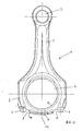
- Fig. 1 of the drawing shows a plan view of an embodiment of a Tarable connecting rod 1 according to the present invention.
- the connecting rod 1 has a small connecting rod 2 for receiving a not shown Piston pin, a connecting rod shaft 3 and a large connecting rod 4 for Recording a crank pin of a crankshaft, not shown.
- the large connecting rod 4 is formed by the connecting rod shaft 3 and a connecting rod cover 5, which can be fixed by means of screws 6 on the connecting rod 3.
- the better representation half, hatched tare mass 7 is provided, which in the illustrated embodiment has an outer contour that corresponds in section to a circle segment.
- the tare mass 7 extends largely to the screws 6 to the area of a tool release 8, which is kept free to a not shown in detail tool for tightening the screws 6 with these in To bring intervention.
- the tare weight is edited so that they are in section a circular segment Has outer contour and the central axis of the circular segment-shaped outer contour with the central axis of the large connecting rod 4 covers.
- the tarable connecting rod has a known tarivable connecting rod a just milled Tariermassenau dichkontur, so that set over the connecting rod cover stiffness jumps, the strong Pressure peaks in the pressure distribution of Pleuellagergleit Mrs 9 lead.
- Fig. 2 shows a perspective view of a portion of the tarable invention Connecting rod with the connecting rod shaft 3, the big eye 4, the Connecting rod cover 5, the screws 6, the tare mass 7, tool releases 8 and arranged on the connecting rod cover 5 so-called screw pipes 10, the Recording the screws 6 serve.
Landscapes
- Engineering & Computer Science (AREA)
- General Engineering & Computer Science (AREA)
- Mechanical Engineering (AREA)
- Shafts, Cranks, Connecting Bars, And Related Bearings (AREA)
Abstract
Description
Claims (6)
- Tarierbare Pleuelstange (1) für insbesondere Brennkraftmaschinen, mit einem kleinen Pleuelauge (2), einem Pleuelschaft (3) und einem geteilten großen Pleuelauge (4), das mittels eines mit Schrauben (6) festlegbaren Pleueldeckels (5) einen Aufnahmeraum für einen Kurbelwellenhubzapfen begrenzt und am Pleueldeckel (5) eine zur mechanischen Bearbeitung vorgesehene Tariermasse (7) angeordnet ist, dadurch gekennzeichnet, dass sich die Tariermasse (7) weitgehend bis zu den Schrauben (6) erstreckt und derart bearbeitet ist, dass der Pleueldeckel (5) von der Pleueldeckelinnenseite zur Außenkontur der Tariermasse (7) eine weitgehend gleichbleibende Wandstärke besitzt.
- Tarierbare Pleuelstange nach Anspruch 1, dadurch gekennzeichnet, dass die Außenkontur der Tariermasse (8) im Schnitt einem Kreissegment entspricht.
- Tarierbare Pleuelstange nach Anspruch 1, dadurch gekennzeichnet, dass die Außenkontur der Tariermasse (7) treppenstufenförmig verläuft.
- Tarierbare Pleuelstange nach Anspruch 2 oder 3, dadurch gekennzeichnet, dass die Tariermasse (7) zur Pleueltarierung über weitgehend die gesamte Breite zwischen den Schrauben (6) bearbeitet ist.
- Tarierbare Pleuelstange nach einem der Ansprüche 1 bis 4, dadurch gekennzeichnet, dass der Flächenmittelpunkt der Grundrissprojektion der Tariermasse (7) mit der Längsmittelachse (11) der Pleuelstange übereinstimmt.
- Tarierbare Pleuelstange nach einem der Ansprüche 1 bis 5, dadurch gekennzeichnet, dass zwischen der Tariermasse (7) und den Schrauben (6) ein Werkzeugfreigang (8) vorgesehen ist.
Applications Claiming Priority (2)
| Application Number | Priority Date | Filing Date | Title |
|---|---|---|---|
| DE10353503 | 2003-11-13 | ||
| DE2003153503 DE10353503A1 (de) | 2003-11-13 | 2003-11-13 | Tarierbare Pleuelstange |
Publications (2)
| Publication Number | Publication Date |
|---|---|
| EP1531277A1 true EP1531277A1 (de) | 2005-05-18 |
| EP1531277B1 EP1531277B1 (de) | 2008-09-24 |
Family
ID=34428759
Family Applications (1)
| Application Number | Title | Priority Date | Filing Date |
|---|---|---|---|
| EP20040023541 Expired - Lifetime EP1531277B1 (de) | 2003-11-13 | 2004-10-02 | Tarierbare Pleuelstange |
Country Status (2)
| Country | Link |
|---|---|
| EP (1) | EP1531277B1 (de) |
| DE (2) | DE10353503A1 (de) |
Families Citing this family (2)
| Publication number | Priority date | Publication date | Assignee | Title |
|---|---|---|---|---|
| DE102014011149A1 (de) | 2014-07-25 | 2016-01-28 | Daimler Ag | Pleuelstange für eine Brennkraftmaschine eines Kraftfahrzeugs |
| DE102015215553A1 (de) * | 2015-08-14 | 2017-02-16 | Bayerische Motoren Werke Aktiengesellschaft | Pleuel |
Citations (3)
| Publication number | Priority date | Publication date | Assignee | Title |
|---|---|---|---|---|
| US1905925A (en) * | 1931-04-16 | 1933-04-25 | Gen Motors Corp | Method of making connecting rods |
| DE4123519C1 (en) * | 1991-07-16 | 1992-09-17 | Mercedes-Benz Aktiengesellschaft, 7000 Stuttgart, De | Weight reduction for connecting rod with split big end bearing - provides recess(es) of specified depth and area for rated value attainment |
| DE4143320A1 (de) * | 1991-07-16 | 1993-01-21 | Daimler Benz Ag | Pleuelstange |
Family Cites Families (1)
| Publication number | Priority date | Publication date | Assignee | Title |
|---|---|---|---|---|
| DE2802603C3 (de) * | 1978-01-21 | 1982-03-04 | Daimler-Benz Ag, 7000 Stuttgart | Geteilter Pleuelkopf |
-
2003
- 2003-11-13 DE DE2003153503 patent/DE10353503A1/de not_active Withdrawn
-
2004
- 2004-10-02 DE DE200450008114 patent/DE502004008114D1/de not_active Expired - Lifetime
- 2004-10-02 EP EP20040023541 patent/EP1531277B1/de not_active Expired - Lifetime
Patent Citations (3)
| Publication number | Priority date | Publication date | Assignee | Title |
|---|---|---|---|---|
| US1905925A (en) * | 1931-04-16 | 1933-04-25 | Gen Motors Corp | Method of making connecting rods |
| DE4123519C1 (en) * | 1991-07-16 | 1992-09-17 | Mercedes-Benz Aktiengesellschaft, 7000 Stuttgart, De | Weight reduction for connecting rod with split big end bearing - provides recess(es) of specified depth and area for rated value attainment |
| DE4143320A1 (de) * | 1991-07-16 | 1993-01-21 | Daimler Benz Ag | Pleuelstange |
Also Published As
| Publication number | Publication date |
|---|---|
| DE502004008114D1 (de) | 2008-11-06 |
| EP1531277B1 (de) | 2008-09-24 |
| DE10353503A1 (de) | 2005-06-23 |
Similar Documents
| Publication | Publication Date | Title |
|---|---|---|
| EP0112494A1 (de) | Vorrichtung zur Steuerung der Ventile einer Brennkraftmaschine über eine Nockenwelle | |
| DE1751736A1 (de) | Mehrkolben-Kraftstoffpumpe | |
| DE3714762A1 (de) | Kolben mit variabler bauhoehe | |
| AT408256B (de) | Vorrichtung zum einbringen von kraftstoff in den brennraum einer brennkraftmaschine | |
| DE102018124697A1 (de) | VCR-Hubkolbenmaschine | |
| DE102016110208A1 (de) | Verfahren zum Betrieb einer Brennkraftmaschine mit einer Zylinderabschaltung | |
| EP1531277A1 (de) | Tarierbare Pleuelstange | |
| DE3632355C2 (de) | ||
| EP0353543B1 (de) | Ventilsteuerung für Brennkraftmaschinen | |
| DE102016212064A1 (de) | Vorrichtung zum Verändern eines Kompressionsverhältnisses einer Hubkolben-Brennkraftmaschine | |
| DE102015210597A1 (de) | Hubkolbenmotor und Kraftfahrzeug | |
| DE4013754A1 (de) | Kolbenmaschine | |
| DE69314925T2 (de) | Hubkolbengiessform | |
| EP1259722A1 (de) | Verfahren zur herstellung von kolben für eine hubkolbenbrennkraftmaschine | |
| DE10135127B4 (de) | Einrichtung zum Verändern des Verdichtungsverhältnisses von Kolbenmaschinen, insbesondere Hubkolbenbrennkraftmaschinen | |
| DE4210029C2 (de) | Verbrennungsmotor mit veränderlichem Verdichtungsraum | |
| DE102010052004A1 (de) | Asymmetrisch geteiltes Gleitlager für eine radiale Lagerschalenmontage | |
| DE10304685A1 (de) | Verbrennungsmotor mit veränderbarem Verdichtungsverhältnis | |
| EP0611878B1 (de) | Verfahren zur Herstellung eines mehrteiligen Zylinderblockes | |
| DE10064981C1 (de) | Verfahren zur Herstellung eines Pleuels mit Buchse und Lagerschalen | |
| DE102017111395A1 (de) | Vorrichtung zur Veränderung des Verdichtungsverhältnisses einer Hubkolbenbrennkraftmaschine | |
| DE3338694C2 (de) | ||
| DE3539216C2 (de) | ||
| DE2550317A1 (de) | Kolben fuer brennkraftmaschinen | |
| DE102015211019A1 (de) | Zylinderkopf für eine ventilgesteuerte Hubkolbenbrennkraftmaschine und Verfahren zum Verändern des Verdichtungsverhältnisses |
Legal Events
| Date | Code | Title | Description |
|---|---|---|---|
| PUAI | Public reference made under article 153(3) epc to a published international application that has entered the european phase |
Free format text: ORIGINAL CODE: 0009012 |
|
| AK | Designated contracting states |
Kind code of ref document: A1 Designated state(s): AT BE BG CH CY CZ DE DK EE ES FI FR GB GR HU IE IT LI LU MC NL PL PT RO SE SI SK TR |
|
| AX | Request for extension of the european patent |
Extension state: AL HR LT LV MK |
|
| 17P | Request for examination filed |
Effective date: 20050609 |
|
| AKX | Designation fees paid |
Designated state(s): DE FR GB IT |
|
| 17Q | First examination report despatched |
Effective date: 20070907 |
|
| GRAP | Despatch of communication of intention to grant a patent |
Free format text: ORIGINAL CODE: EPIDOSNIGR1 |
|
| GRAC | Information related to communication of intention to grant a patent modified |
Free format text: ORIGINAL CODE: EPIDOSCIGR1 |
|
| GRAS | Grant fee paid |
Free format text: ORIGINAL CODE: EPIDOSNIGR3 |
|
| GRAA | (expected) grant |
Free format text: ORIGINAL CODE: 0009210 |
|
| AK | Designated contracting states |
Kind code of ref document: B1 Designated state(s): DE FR GB IT |
|
| REG | Reference to a national code |
Ref country code: GB Ref legal event code: FG4D Free format text: NOT ENGLISH |
|
| REF | Corresponds to: |
Ref document number: 502004008114 Country of ref document: DE Date of ref document: 20081106 Kind code of ref document: P |
|
| PLBE | No opposition filed within time limit |
Free format text: ORIGINAL CODE: 0009261 |
|
| STAA | Information on the status of an ep patent application or granted ep patent |
Free format text: STATUS: NO OPPOSITION FILED WITHIN TIME LIMIT |
|
| 26N | No opposition filed |
Effective date: 20090625 |
|
| REG | Reference to a national code |
Ref country code: FR Ref legal event code: PLFP Year of fee payment: 12 |
|
| REG | Reference to a national code |
Ref country code: FR Ref legal event code: PLFP Year of fee payment: 13 |
|
| REG | Reference to a national code |
Ref country code: FR Ref legal event code: PLFP Year of fee payment: 14 |
|
| REG | Reference to a national code |
Ref country code: FR Ref legal event code: PLFP Year of fee payment: 15 |
|
| P01 | Opt-out of the competence of the unified patent court (upc) registered |
Effective date: 20230502 |
|
| PGFP | Annual fee paid to national office [announced via postgrant information from national office to epo] |
Ref country code: GB Payment date: 20231025 Year of fee payment: 20 |
|
| PGFP | Annual fee paid to national office [announced via postgrant information from national office to epo] |
Ref country code: IT Payment date: 20231031 Year of fee payment: 20 Ref country code: FR Payment date: 20231023 Year of fee payment: 20 Ref country code: DE Payment date: 20231017 Year of fee payment: 20 |
|
| REG | Reference to a national code |
Ref country code: DE Ref legal event code: R071 Ref document number: 502004008114 Country of ref document: DE |
|
| PG25 | Lapsed in a contracting state [announced via postgrant information from national office to epo] |
Ref country code: GB Free format text: LAPSE BECAUSE OF EXPIRATION OF PROTECTION Effective date: 20241001 |
|
| REG | Reference to a national code |
Ref country code: GB Ref legal event code: PE20 Expiry date: 20241001 |
|
| PG25 | Lapsed in a contracting state [announced via postgrant information from national office to epo] |
Ref country code: GB Free format text: LAPSE BECAUSE OF EXPIRATION OF PROTECTION Effective date: 20241001 |