EP1531094A1 - Airbagmodul - Google Patents
Airbagmodul Download PDFInfo
- Publication number
- EP1531094A1 EP1531094A1 EP04025343A EP04025343A EP1531094A1 EP 1531094 A1 EP1531094 A1 EP 1531094A1 EP 04025343 A EP04025343 A EP 04025343A EP 04025343 A EP04025343 A EP 04025343A EP 1531094 A1 EP1531094 A1 EP 1531094A1
- Authority
- EP
- European Patent Office
- Prior art keywords
- gas bag
- edge
- fixing element
- injection opening
- module according
- Prior art date
- Legal status (The legal status is an assumption and is not a legal conclusion. Google has not performed a legal analysis and makes no representation as to the accuracy of the status listed.)
- Granted
Links
- 238000002347 injection Methods 0.000 claims description 33
- 239000007924 injection Substances 0.000 claims description 33
- 230000000694 effects Effects 0.000 claims description 4
- 230000009471 action Effects 0.000 description 5
- 238000000034 method Methods 0.000 description 5
- 239000000853 adhesive Substances 0.000 description 2
- 230000001070 adhesive effect Effects 0.000 description 2
- 238000009958 sewing Methods 0.000 description 2
- 230000008719 thickening Effects 0.000 description 2
- 238000009941 weaving Methods 0.000 description 2
- 230000004913 activation Effects 0.000 description 1
- 238000004026 adhesive bonding Methods 0.000 description 1
- 230000008878 coupling Effects 0.000 description 1
- 238000010168 coupling process Methods 0.000 description 1
- 238000005859 coupling reaction Methods 0.000 description 1
- 239000004744 fabric Substances 0.000 description 1
- 239000002184 metal Substances 0.000 description 1
- 230000008569 process Effects 0.000 description 1
Images



Classifications
-
- B—PERFORMING OPERATIONS; TRANSPORTING
- B60—VEHICLES IN GENERAL
- B60R—VEHICLES, VEHICLE FITTINGS, OR VEHICLE PARTS, NOT OTHERWISE PROVIDED FOR
- B60R21/00—Arrangements or fittings on vehicles for protecting or preventing injuries to occupants or pedestrians in case of accidents or other traffic risks
- B60R21/02—Occupant safety arrangements or fittings, e.g. crash pads
- B60R21/16—Inflatable occupant restraints or confinements designed to inflate upon impact or impending impact, e.g. air bags
- B60R21/20—Arrangements for storing inflatable members in their non-use or deflated condition; Arrangement or mounting of air bag modules or components
- B60R21/217—Inflation fluid source retainers, e.g. reaction canisters; Connection of bags, covers, diffusers or inflation fluid sources therewith or together
Definitions
- the invention relates to an airbag module with a carrier part, an airbag with an injection opening surrounded by an edge, a gas bag holding element, wherein the edge of the injection opening between the gas bag holding element and the support part is arranged, and with at least one at the edge of the Einblasö réelle provided with the gas bag coupled fixing.
- the attachment of the gas bag to a Carrier part which e.g. Part of a module housing can be improved before especially with a load acting on the gas bag, e.g. when unfolding the Gas bags or when hitting a vehicle occupant on the gas bag.
- a load acting on the gas bag e.g. when unfolding the Gas bags or when hitting a vehicle occupant on the gas bag.
- the invention has as its object the fixation of the gas bag on the carrier part to optimize.
- the fixing element seen in a radial section at least partially wedge or trapezoidal and so arranged to the gas bag holding member and the support member is that the fixing is endeavored under a load of the gas bag, through a movement between the carrier part and gas bag holding element due to a Wedge effect to remove these from each other.
- This design can be optionally the fixing element by a small distance radially outward move when a load on the gas bag acts, which is gradually on the gas bag by the holding element and the support member exerted clamping action strengthened. The gas bag is thus not slowed down suddenly, so that the maximum forces, which act on the edge of the injection opening, compared to a known Gas bag attachment can be reduced.
- the gas bag holding member on the support part e.g. a known screw connection
- the clamping action is proportional to the increases the force acting on the gas bag, when the fixing element between Gas bag holding element and support member pushes, automatically increases the on the Edge of the injection opening acting clamping force. Therefore, the height of a bias, the above mentioned fasteners on the edge of the Einblasö réelle is exercised, not only for the fixation of the gas bag responsible in case of load.
- the fixing element may, for example, be subject to loading of the gas bag, e.g. between the Carrier part and the gas bag holding element to be clamped and finally immovable be positioned.
- annular fixing element which the injection opening completely surrounds.
- several, e.g. four or five, separate from each other fixing elements are provided on the above Scope of the injection opening distributed locations are arranged.
- the fixing elements may be designed as a ring segment to a uniform To achieve clamping action.
- the fixing element could also be called a slotted ring be educated.
- annular here are not only annular components, but in general, other forms with an internal recess to understand.
- the Fixing element is dimensionally stable, ie not or only insignificantly in the clamping deformed.
- the wedge-shaped or trapezoidal section is also intended in this form have an unloaded state and this not only during a Accept clamping process.
- the fixing element is a separate component and not in one piece e.g. executed with the gas bag or the gas bag holding member.
- the fixing element may be embedded in the edge of the injection opening, e.g. by sewing or weaving.
- the fixing can be with the gas bag also by gluing, either as an exclusive attachment or in addition to sewing or weaving.
- the coupling of the fixing with the gas bag thereby make that a directed to the edge of the injection port side of the Roughened fixing element or is suitably structured to the friction between Increase fixation and gas bag fabric. In this case can on a further attachment can be omitted.
- the gas bag holding element and / or the carrier part in the region of the edge of the injection opening a the slope of the fixing element corresponding contour. So will at one Loading of the gas bag for a very uniform clamping and the others a uniformly increasing load on the edge of the injection opening reached. It is immaterial here, whether the inclined clamping surface on the for Gas bag holding element, which is directed towards the carrier part or on both sides of the Fixing element is formed. It is important here that the contour of an between Carrier part and gas bag element formed receiving space in which the fixing is arranged, the outer contour of the fixing element corresponds.
- the gas bag may be in an adjacent to the edge of the injection opening Be clamped area between gas bag holding element and carrier part to regardless of a load on the gas bag whose fixation on the support part too guarantee.
- the gas bag retaining element can also be a separate gas bag retaining ring but also on a flange of a gas generator or on another be formed suitable component.
- the carrier part of the gas bag module is usually by a generator carrier, a housing or another component formed of the gas bag module, which ultimately with a vehicle-fixed component, e.g. a steering wheel is connected.
- FIG. 1 shows an airbag module 10 which is inserted in a steering wheel 12.
- the Airbag module 10 includes a received in a cup-shaped support member 14, folded airbag 16.
- An edge 18 of an injection opening of the gas bag 16th is located between a bottom 17 of the support member 14 and a separate annular Gas bag retaining element 20.
- the bottom 17 of the support member 14 has a Opening in which a gas generator 22 with an annular flange 24th is used (see also Figure 2), which is also between the gas bag holding element 20 and the bottom 17 of the support member 14 is arranged.
- An edge region 28 of the airbag retaining element lying in the radial direction R 20 is bent upward in an axial direction A of the gas bag module 10, so that the flange 24 of the gas generator 22 is detected and clamped thereunder can be.
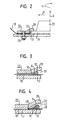
- a receiving space 30 is formed (see FIGS. 3 and 4), in which a fixing element 32 is arranged.
- the fixing element 32 is connected to the Edge 18 of the injection opening of the gas bag 16 is coupled.
- Each fuser 32 is a separate, e.g. made of plastic or metal, dimensionally stable component.
- the fixing element 32 runs in the radial direction R wedge-shaped and has a Clamping surface 34, which seen in a section in the radial direction R and with respect to the axial direction A is inclined radially outwards, so that the tip 36th of the wedge points radially outward.
- the edge 18 of the injection opening is at least loaded radially outwardly at some points of its circumference.
- This burden is transferred to the fixing member 32 so that this also radially to moved outside.
- the wedge-shaped section of the fixing element 32 arrives with the clamping surface 34 in contact with the inside of the receiving space 30, in In this case, to the inside of the edge region 28 of the support part 14 facing Gas bag retaining element 20.
- the coordinated contours pushes the fixing element 32 uniformly and continuously between the gas bag holding element 20 and the support member 14 and moves these components in the axial direction A apart.
- the fixing element 32 lies on the edge 18 of the injection opening and is coupled to the edge 18 of the gas bag 16, by roughened to the edge 18 side of the fixing element 32 or roughened is suitably structured to a high degree of friction with the tissue of the gas bag 16 to achieve (shown schematically in Figure 3c).
- the fixing element 32 can also by means of an adhesive 42 with the edge 18th be connected to the injection opening.
- An adhesive bond can be either in addition to another method of attachment or exclusive Fixing method of the fixing element 32 on the gas bag 16 are used.
- the fixing element 32 rigid in itself and so dimensionally stable that it is at a load of Gas bag 16 is not or only slightly deformed.
- the wedge-shaped section has this shape without a burden on the gas bag 16th
- the fixing element has an inclined only on one side Clamping surface 34 on.
- the top 36 of the Fixing element 32 may also be aligned obliquely to the axial direction A. In this case, of course, the contour of the receiving space 30 must be corresponding be adjusted.
- Fixing element 32 with a trapezoidal cross-section (see Figure 3c) to use or a clamping surface 34 with a nonlinear, e.g. use convex or concave inclination.
- a portion of the Fixing element 32 may be wedge-shaped or trapezoidal.
- FIGS. 5 to 10 show further possibilities, an edge 118 an injection opening of a gas bag between two components, e.g. one Support member 117 and a gas bag holding member 120 to fix.
- the airbag retaining element 120 has a Projection 150, while in the support member 117 a projection 150 corresponding Groove 152 is formed.
- gas bag holding element 120 has a Recess 160 provided, which has a receiving space for a through seams 162 formed thickening in the edge 118 of the injection opening. Under pressure on the edge 118, the thickening is pulled radially outward and on the inclined inner wall 164 of the recess 160 clamped.
- FIG. 7 combines the fixing methods from the figures 5 and 6.
- a recess 160 for receiving a Verdikkung formed by stitching 162 on a projection 150 In the support part 117 is a projection 150th corresponding groove 152 is formed.
- FIG. 8 is one of the other components shown separate fixing element 180 provided with a circular cross-section, which lies in a groove 182 in the carrier part 117.
- the edge 118 of the Einblasö réelle runs between the fixing member 180 and the support member 117th At a tensile load in the radial direction R on the edge 118 results in a Clamping action between the support member 117 and the fixing member 180.
- FIG 9 substantially corresponds to the example Figure 8, with the difference that also in the gas bag holding element 120 in the Contour the cross section of the fixing member 180 corresponding recess 194th is provided.
- FIG. 10 essentially corresponds to that in FIG. 9 shown example, with the difference that the fixing element 200 is a rectangular Has cross section and that the recesses 202, 204 in the gas bag holding member 120 or support member 117 only at the radially outward Side are beveled and run towards each other while their distance on the radially inner side remains enlarged.
- the illustrated radial direction R refers to all figures 5 to 10.
- the clamping effect becomes on the edge 118 of the injection opening of the gas bag, the support member 117 and the gas bag holding member 120 is exerted by a suitable shape thereof two components, the edge 118 of the gas bag or an additional separate Fixing element 180, 200, reinforced.
Landscapes
- Engineering & Computer Science (AREA)
- Mechanical Engineering (AREA)
- Air Bags (AREA)
Abstract
Description
- Figur 1 eine schematische halbseitige Schnittansicht eines erfindungsgemäßen Gassackmoduls;
- Figur 2 einen vergrößerten Ausschnitt aus Figur 1;
- Figur 3 einen vergrößerten Ausschnitt aus Figur 2 gemäß einer ersten Variante eines erfindungsgemäßen Gassackmoduls;
- Figuren 3a bis 3c verschiedene Ausbildungen eines Fixierelements eines erfindungsgemäßen Gassackmoduls;
- Figur 4 einen vergrößerten Ausschnitt aus Figur 2 gemäß einer zweiten Variante eines erfindungsgemäßen Gassackmoduls; und
- Figur 5 bis Figur 10 weitere Möglichkeiten zur Befestigung eines Gassacks an einem Trägerteil.
Claims (10)
- Gassackmodul
mit einem Trägerteil (14),
einem Gassack (16) mit einer von einem Rand (18) umgebenen Einblasöffnung,
einem Gassackhalteelement (20),
wobei der Rand (18) der Einblasöffnung zwischen dem Gassackhalteelement (20) und dem Trägerteil (14) angeordnet ist, und mit
wenigstens einem am Rand (18) der Einblasöffnung vorgesehenen, mit dem Gassack (16) gekoppelten Fixierelement (32),
dadurch gekennzeichnet, daß das Fixierelement (32) in einem radialen Schnitt gesehen zumindest abschnittsweise keil- oder trapezförmig und so zum Gassackhalteelement (20) und zum Trägerteil (14) angeordnet ist, daß das Fixierelement (32) bei einer Belastung des Gassacks (16) bestrebt ist, durch eine Bewegung zwischen Trägerteil (14) und Gassackhalteelement (20) aufgrund einer Keilwirkung diese voneinander zu entfernen. - Gassackmodul nach Anspruch 1, dadurch gekennzeichnet, daß das Fixierelement (32) bei einer Belastung des Gassacks (16) zwischen dem Trägerteil (14) und dem Gassackhalteelement (20) geklemmt ist.
- Gassackmodul nach einem der vorhergehenden Ansprüche, dadurch gekennzeichnet daß das Fixierelement (32) ringförmig ist.
- Gassackmodul nach einem der vorhergehenden Ansprüche, dadurch gekennzeichnet, daß das Fixierelement (32) formstabil ist.
- Gassackmodul nach einem der vorhergehenden Ansprüche, dadurch gekennzeichnet, daß das Fixierelement (32) ein separates Bauteil ist.
- Gassackmodul nach einem der vorhergehenden Ansprüche, dadurch gekennzeichnet, daß das Fixierelement (32) in den Rand (18) der Einblasöffnung eingebettet ist.
- Gassackmodul nach einem der vorhergehenden Ansprüche, dadurch gekennzeichnet, daß das Fixierelement (32) in den Rand (18) der Einblasöffnung eingewebt oder eingenäht ist.
- Gassackmodul nach einem der vorhergehenden Ansprüche, dadurch gekennzeichnet, daß das Fixierelement (32) mit dem Rand (18) der Einblasöffnung durch Kleben verbunden ist.
- Gassackmodul nach einem der vorhergehenden Ansprüche, dadurch gekennzeichnet, daß das Gassackhalteelement (20) und/oder das Trägerteil (14) im Bereich des Randes (18) der Einblasöffnung eine der Schräge des Fixierelements (32) entsprechende Kontur aufweisen.
- Gassackmodul nach einem der vorhergehenden Ansprüche, dadurch gekennzeichnet, daß der Gassack (16) in einem an den Rand (18) der Einblasöffnung angrenzenden Bereich zwischen Gassackhalteelement (20) und Trägerteil (14) geklemmt ist.
Applications Claiming Priority (2)
| Application Number | Priority Date | Filing Date | Title |
|---|---|---|---|
| DE20317611U | 2003-11-14 | ||
| DE20317611U DE20317611U1 (de) | 2003-11-14 | 2003-11-14 | Gassackmodul |
Publications (2)
| Publication Number | Publication Date |
|---|---|
| EP1531094A1 true EP1531094A1 (de) | 2005-05-18 |
| EP1531094B1 EP1531094B1 (de) | 2006-11-22 |
Family
ID=32087581
Family Applications (1)
| Application Number | Title | Priority Date | Filing Date |
|---|---|---|---|
| EP04025343A Expired - Lifetime EP1531094B1 (de) | 2003-11-14 | 2004-10-25 | Airbagmodul |
Country Status (3)
| Country | Link |
|---|---|
| US (1) | US20050104336A1 (de) |
| EP (1) | EP1531094B1 (de) |
| DE (2) | DE20317611U1 (de) |
Families Citing this family (8)
| Publication number | Priority date | Publication date | Assignee | Title |
|---|---|---|---|---|
| DE20315347U1 (de) * | 2003-09-30 | 2003-12-18 | Takata-Petri Ag | Anordnung zur Befestigung eines Gassacks in einem Fahrer-Airbagmodul |
| DE202005011878U1 (de) * | 2005-07-21 | 2005-10-13 | Takata-Petri Ag | Airbagmodul für ein Kraftfahrzeug |
| DE202006000843U1 (de) | 2006-01-13 | 2006-04-06 | Takata-Petri Ag | Gassackbefestigung in einem Airbagmodul mittels einer Klemmverbindung |
| JP5117838B2 (ja) * | 2007-12-13 | 2013-01-16 | タカタ株式会社 | エアバッグ装置 |
| DE102010044611B4 (de) * | 2010-08-13 | 2019-05-09 | Autoliv Development Ab | Gassack mit wenigstens einem Verbinder |
| DE102010052782A1 (de) * | 2010-11-30 | 2012-05-31 | Trw Automotive Gmbh | Fahrzeuginsassenrückhaltesystem für ein Fahrzeug und Dichtungselement |
| CN108279514A (zh) * | 2017-12-29 | 2018-07-13 | 重庆市中光电显示技术有限公司 | 一种偏光片装载装置 |
| DE102024129199A1 (de) | 2024-10-09 | 2026-04-09 | Autoliv Development Ab | Airbag-Rückhaltevorrichtung |
Citations (6)
| Publication number | Priority date | Publication date | Assignee | Title |
|---|---|---|---|---|
| EP0364267A2 (de) * | 1988-10-14 | 1990-04-18 | Irvin Automotive Products, Inc. | Rückhaltesystem für Fahrzeuginsassen |
| US5152549A (en) * | 1991-04-22 | 1992-10-06 | Trw Inc. | Vehicle safety apparatus having a retainer for clamping an inflator against a support plate |
| US5368327A (en) * | 1989-07-12 | 1994-11-29 | Toyoda Gosei, Co., Ltd. | Air bag device |
| US5518266A (en) * | 1994-10-20 | 1996-05-21 | Trw Inc. | Vehicle safety apparatus including inflatable restraint |
| US6250665B1 (en) * | 1998-12-15 | 2001-06-26 | Trw Vehicle Safety Systems Inc. | Retainer structure for an inflatable vehicle occupant protection device |
| US6371507B1 (en) * | 1995-09-15 | 2002-04-16 | Breed Automotive Technology, Inc. | Worm gear drive for modular steering wheel and airbag combination |
Family Cites Families (1)
| Publication number | Priority date | Publication date | Assignee | Title |
|---|---|---|---|---|
| DE10027240B4 (de) * | 2000-05-31 | 2016-11-17 | Autoliv Development Ab | Luftsackmodul für Kraftfahrzeuge |
-
2003
- 2003-11-14 DE DE20317611U patent/DE20317611U1/de not_active Expired - Lifetime
-
2004
- 2004-10-25 EP EP04025343A patent/EP1531094B1/de not_active Expired - Lifetime
- 2004-10-25 DE DE502004002074T patent/DE502004002074D1/de not_active Expired - Fee Related
- 2004-11-08 US US10/983,480 patent/US20050104336A1/en not_active Abandoned
Patent Citations (6)
| Publication number | Priority date | Publication date | Assignee | Title |
|---|---|---|---|---|
| EP0364267A2 (de) * | 1988-10-14 | 1990-04-18 | Irvin Automotive Products, Inc. | Rückhaltesystem für Fahrzeuginsassen |
| US5368327A (en) * | 1989-07-12 | 1994-11-29 | Toyoda Gosei, Co., Ltd. | Air bag device |
| US5152549A (en) * | 1991-04-22 | 1992-10-06 | Trw Inc. | Vehicle safety apparatus having a retainer for clamping an inflator against a support plate |
| US5518266A (en) * | 1994-10-20 | 1996-05-21 | Trw Inc. | Vehicle safety apparatus including inflatable restraint |
| US6371507B1 (en) * | 1995-09-15 | 2002-04-16 | Breed Automotive Technology, Inc. | Worm gear drive for modular steering wheel and airbag combination |
| US6250665B1 (en) * | 1998-12-15 | 2001-06-26 | Trw Vehicle Safety Systems Inc. | Retainer structure for an inflatable vehicle occupant protection device |
Also Published As
| Publication number | Publication date |
|---|---|
| US20050104336A1 (en) | 2005-05-19 |
| DE502004002074D1 (de) | 2007-01-04 |
| EP1531094B1 (de) | 2006-11-22 |
| DE20317611U1 (de) | 2004-04-01 |
Similar Documents
| Publication | Publication Date | Title |
|---|---|---|
| DE69001177T2 (de) | Luftsackeinbau. | |
| DE4033835B4 (de) | Luftsack | |
| DE4139492C2 (de) | Gassack | |
| DE4139451C2 (de) | Gassack | |
| DE102005057499B4 (de) | Fahrzeugsitz-Anordnung mit einem aufblasbaren Airbag | |
| DE112004001981T5 (de) | System zum Halten eines aufblasbaren Kissens | |
| DE4240760A1 (de) | ||
| DE4410964A1 (de) | Kunstharzmanschette | |
| EP1531094B1 (de) | Airbagmodul | |
| DE102006023128A1 (de) | Bezugsbefestigungskomponente und entsprechendes Verfahren | |
| WO2018069149A1 (de) | Front-gassack für fahrzeuginsassen | |
| EP1591324A1 (de) | Gassack | |
| DE102017124029A1 (de) | Gassack für ein kraftfahrzeug sowie verfahren zur befestigung eines haltebands am gassackgewebe eines gassacks | |
| EP0844153B1 (de) | Schlossstraffer | |
| DE102013018824A1 (de) | Airbag mit Befestigungsmittel | |
| DE102013012017A1 (de) | Airbag | |
| DE102011011500A1 (de) | Sicherheitsgurt für ein Fahrzeug | |
| EP1046548B1 (de) | Knie-Rückhalteeinrichtung für Fahrzeuge | |
| DE4215833C2 (de) | Gassackbefestigung | |
| EP1971505B1 (de) | Gassackbefestigung in einem airbagmodul mittels einer klemmverbindung | |
| DE20315347U1 (de) | Anordnung zur Befestigung eines Gassacks in einem Fahrer-Airbagmodul | |
| EP4015863A1 (de) | Vorrichtung zum lagern mindestens eines bauteils in einem fahrzeug und fahrzeug oder fahrzeugelement umfassend diese vorrichtung | |
| DE102016200998A1 (de) | Sitzanordnung mit Seitenairbag | |
| DE102007008649B4 (de) | Airbag | |
| DE102005016211B4 (de) | Befestigungsanordnung für einen Sicherheitsgurt |
Legal Events
| Date | Code | Title | Description |
|---|---|---|---|
| PUAI | Public reference made under article 153(3) epc to a published international application that has entered the european phase |
Free format text: ORIGINAL CODE: 0009012 |
|
| AK | Designated contracting states |
Kind code of ref document: A1 Designated state(s): AT BE BG CH CY CZ DE DK EE ES FI FR GB GR HU IE IT LI LU MC NL PL PT RO SE SI SK TR |
|
| AX | Request for extension of the european patent |
Extension state: AL HR LT LV MK |
|
| 17P | Request for examination filed |
Effective date: 20051017 |
|
| GRAP | Despatch of communication of intention to grant a patent |
Free format text: ORIGINAL CODE: EPIDOSNIGR1 |
|
| AKX | Designation fees paid |
Designated state(s): DE ES FR IT |
|
| GRAS | Grant fee paid |
Free format text: ORIGINAL CODE: EPIDOSNIGR3 |
|
| GRAA | (expected) grant |
Free format text: ORIGINAL CODE: 0009210 |
|
| AK | Designated contracting states |
Kind code of ref document: B1 Designated state(s): DE ES FR IT |
|
| PG25 | Lapsed in a contracting state [announced via postgrant information from national office to epo] |
Ref country code: IT Free format text: LAPSE BECAUSE OF FAILURE TO SUBMIT A TRANSLATION OF THE DESCRIPTION OR TO PAY THE FEE WITHIN THE PRESCRIBED TIME-LIMIT;WARNING: LAPSES OF ITALIAN PATENTS WITH EFFECTIVE DATE BEFORE 2007 MAY HAVE OCCURRED AT ANY TIME BEFORE 2007. THE CORRECT EFFECTIVE DATE MAY BE DIFFERENT FROM THE ONE RECORDED. Effective date: 20061122 |
|
| REF | Corresponds to: |
Ref document number: 502004002074 Country of ref document: DE Date of ref document: 20070104 Kind code of ref document: P |
|
| PG25 | Lapsed in a contracting state [announced via postgrant information from national office to epo] |
Ref country code: ES Free format text: LAPSE BECAUSE OF FAILURE TO SUBMIT A TRANSLATION OF THE DESCRIPTION OR TO PAY THE FEE WITHIN THE PRESCRIBED TIME-LIMIT Effective date: 20070305 |
|
| EN | Fr: translation not filed | ||
| PLBE | No opposition filed within time limit |
Free format text: ORIGINAL CODE: 0009261 |
|
| STAA | Information on the status of an ep patent application or granted ep patent |
Free format text: STATUS: NO OPPOSITION FILED WITHIN TIME LIMIT |
|
| 26N | No opposition filed |
Effective date: 20070823 |
|
| PG25 | Lapsed in a contracting state [announced via postgrant information from national office to epo] |
Ref country code: FR Free format text: LAPSE BECAUSE OF FAILURE TO SUBMIT A TRANSLATION OF THE DESCRIPTION OR TO PAY THE FEE WITHIN THE PRESCRIBED TIME-LIMIT Effective date: 20070713 |
|
| PG25 | Lapsed in a contracting state [announced via postgrant information from national office to epo] |
Ref country code: DE Free format text: LAPSE BECAUSE OF NON-PAYMENT OF DUE FEES Effective date: 20080501 |
|
| PG25 | Lapsed in a contracting state [announced via postgrant information from national office to epo] |
Ref country code: FR Free format text: LAPSE BECAUSE OF FAILURE TO SUBMIT A TRANSLATION OF THE DESCRIPTION OR TO PAY THE FEE WITHIN THE PRESCRIBED TIME-LIMIT Effective date: 20061122 |