EP1530992B1 - Elément filtrant pour retenir les contaminants grossiers d'un liquide en écoulement - Google Patents
Elément filtrant pour retenir les contaminants grossiers d'un liquide en écoulement Download PDFInfo
- Publication number
- EP1530992B1 EP1530992B1 EP04022628A EP04022628A EP1530992B1 EP 1530992 B1 EP1530992 B1 EP 1530992B1 EP 04022628 A EP04022628 A EP 04022628A EP 04022628 A EP04022628 A EP 04022628A EP 1530992 B1 EP1530992 B1 EP 1530992B1
- Authority
- EP
- European Patent Office
- Prior art keywords
- filter
- filter element
- set forth
- tube
- elongate
- Prior art date
- Legal status (The legal status is an assumption and is not a legal conclusion. Google has not performed a legal analysis and makes no representation as to the accuracy of the status listed.)
- Expired - Lifetime
Links
- 239000007788 liquid Substances 0.000 title claims description 20
- 238000001914 filtration Methods 0.000 title description 3
- 239000000356 contaminant Substances 0.000 title 1
- 239000000463 material Substances 0.000 claims description 14
- 238000010276 construction Methods 0.000 claims description 5
- 239000011796 hollow space material Substances 0.000 claims 2
- 230000000717 retained effect Effects 0.000 claims 1
- XLYOFNOQVPJJNP-UHFFFAOYSA-N water Substances O XLYOFNOQVPJJNP-UHFFFAOYSA-N 0.000 description 16
- 239000003822 epoxy resin Substances 0.000 description 8
- 229920000647 polyepoxide Polymers 0.000 description 8
- 241000251468 Actinopterygii Species 0.000 description 7
- 239000002184 metal Substances 0.000 description 5
- 239000004033 plastic Substances 0.000 description 4
- 244000089486 Phragmites australis subsp australis Species 0.000 description 3
- 238000004519 manufacturing process Methods 0.000 description 3
- 239000011230 binding agent Substances 0.000 description 2
- 230000005611 electricity Effects 0.000 description 2
- 230000007774 longterm Effects 0.000 description 2
- 238000005259 measurement Methods 0.000 description 2
- 230000035699 permeability Effects 0.000 description 2
- 239000003053 toxin Substances 0.000 description 2
- 231100000765 toxin Toxicity 0.000 description 2
- 108700012359 toxins Proteins 0.000 description 2
- 241000195493 Cryptophyta Species 0.000 description 1
- 239000004593 Epoxy Substances 0.000 description 1
- 239000004677 Nylon Substances 0.000 description 1
- 238000005299 abrasion Methods 0.000 description 1
- 239000000853 adhesive Substances 0.000 description 1
- 238000004026 adhesive bonding Methods 0.000 description 1
- 230000001070 adhesive effect Effects 0.000 description 1
- 239000007767 bonding agent Substances 0.000 description 1
- 239000011248 coating agent Substances 0.000 description 1
- 238000000576 coating method Methods 0.000 description 1
- 150000001875 compounds Chemical class 0.000 description 1
- 238000011161 development Methods 0.000 description 1
- 239000010791 domestic waste Substances 0.000 description 1
- 238000002474 experimental method Methods 0.000 description 1
- 230000002349 favourable effect Effects 0.000 description 1
- 239000012530 fluid Substances 0.000 description 1
- 239000008235 industrial water Substances 0.000 description 1
- 238000003780 insertion Methods 0.000 description 1
- 230000037431 insertion Effects 0.000 description 1
- 230000001788 irregular Effects 0.000 description 1
- 238000012423 maintenance Methods 0.000 description 1
- 230000014759 maintenance of location Effects 0.000 description 1
- 239000011159 matrix material Substances 0.000 description 1
- 229920001778 nylon Polymers 0.000 description 1
- 239000002245 particle Substances 0.000 description 1
- 230000000149 penetrating effect Effects 0.000 description 1
- 239000004576 sand Substances 0.000 description 1
- 239000007787 solid Substances 0.000 description 1
- 238000011144 upstream manufacturing Methods 0.000 description 1
- 239000003643 water by type Substances 0.000 description 1
- 238000003466 welding Methods 0.000 description 1
Images
Classifications
-
- B—PERFORMING OPERATIONS; TRANSPORTING
- B01—PHYSICAL OR CHEMICAL PROCESSES OR APPARATUS IN GENERAL
- B01D—SEPARATION
- B01D39/00—Filtering material for liquid or gaseous fluids
- B01D39/14—Other self-supporting filtering material ; Other filtering material
- B01D39/20—Other self-supporting filtering material ; Other filtering material of inorganic material, e.g. asbestos paper, metallic filtering material of non-woven wires
- B01D39/2068—Other inorganic materials, e.g. ceramics
- B01D39/2072—Other inorganic materials, e.g. ceramics the material being particulate or granular
- B01D39/2075—Other inorganic materials, e.g. ceramics the material being particulate or granular sintered or bonded by inorganic agents
-
- B—PERFORMING OPERATIONS; TRANSPORTING
- B01—PHYSICAL OR CHEMICAL PROCESSES OR APPARATUS IN GENERAL
- B01D—SEPARATION
- B01D29/00—Filters with filtering elements stationary during filtration, e.g. pressure or suction filters, not covered by groups B01D24/00 - B01D27/00; Filtering elements therefor
- B01D29/11—Filters with filtering elements stationary during filtration, e.g. pressure or suction filters, not covered by groups B01D24/00 - B01D27/00; Filtering elements therefor with bag, cage, hose, tube, sleeve or like filtering elements
- B01D29/111—Making filtering elements
-
- B—PERFORMING OPERATIONS; TRANSPORTING
- B01—PHYSICAL OR CHEMICAL PROCESSES OR APPARATUS IN GENERAL
- B01D—SEPARATION
- B01D29/00—Filters with filtering elements stationary during filtration, e.g. pressure or suction filters, not covered by groups B01D24/00 - B01D27/00; Filtering elements therefor
- B01D29/11—Filters with filtering elements stationary during filtration, e.g. pressure or suction filters, not covered by groups B01D24/00 - B01D27/00; Filtering elements therefor with bag, cage, hose, tube, sleeve or like filtering elements
- B01D29/13—Supported filter elements
- B01D29/15—Supported filter elements arranged for inward flow filtration
-
- B—PERFORMING OPERATIONS; TRANSPORTING
- B01—PHYSICAL OR CHEMICAL PROCESSES OR APPARATUS IN GENERAL
- B01D—SEPARATION
- B01D29/00—Filters with filtering elements stationary during filtration, e.g. pressure or suction filters, not covered by groups B01D24/00 - B01D27/00; Filtering elements therefor
- B01D29/50—Filters with filtering elements stationary during filtration, e.g. pressure or suction filters, not covered by groups B01D24/00 - B01D27/00; Filtering elements therefor with multiple filtering elements, characterised by their mutual disposition
- B01D29/52—Filters with filtering elements stationary during filtration, e.g. pressure or suction filters, not covered by groups B01D24/00 - B01D27/00; Filtering elements therefor with multiple filtering elements, characterised by their mutual disposition in parallel connection
-
- B—PERFORMING OPERATIONS; TRANSPORTING
- B01—PHYSICAL OR CHEMICAL PROCESSES OR APPARATUS IN GENERAL
- B01D—SEPARATION
- B01D29/00—Filters with filtering elements stationary during filtration, e.g. pressure or suction filters, not covered by groups B01D24/00 - B01D27/00; Filtering elements therefor
- B01D29/88—Filters with filtering elements stationary during filtration, e.g. pressure or suction filters, not covered by groups B01D24/00 - B01D27/00; Filtering elements therefor having feed or discharge devices
- B01D29/92—Filters with filtering elements stationary during filtration, e.g. pressure or suction filters, not covered by groups B01D24/00 - B01D27/00; Filtering elements therefor having feed or discharge devices for discharging filtrate
- B01D29/925—Filters with filtering elements stationary during filtration, e.g. pressure or suction filters, not covered by groups B01D24/00 - B01D27/00; Filtering elements therefor having feed or discharge devices for discharging filtrate containing liquid displacement elements or cores
-
- B—PERFORMING OPERATIONS; TRANSPORTING
- B01—PHYSICAL OR CHEMICAL PROCESSES OR APPARATUS IN GENERAL
- B01D—SEPARATION
- B01D2201/00—Details relating to filtering apparatus
- B01D2201/04—Supports for the filtering elements
- B01D2201/043—Filter tubes connected to plates
Definitions
- the present invention relates to an elongate filter element for retaining coarse matter in a flowing liquid.
- filter elements for hydraulic engineering plants.
- the filter elements according to the invention are suitable to be used in connection with hydropower plants.
- hydropower is used to generate electricity.
- Streaming water for example, sets a turbine or water wheel in motion, which then drives a generator to generate electricity.
- the use of hydropower is particularly in areas with Vorflutern, rivers or streams possible, but it is also possible to use industrial waters.
- rakes are used, which are used in the flow of water to be cleaned or used to filter out flotsam from this.
- flotsam for example, leaves, household waste, branches, etc. is but also the filtering out of smaller particles, such as sand or parts of plants necessary.
- filter systems are therefore usually so wide that substantially the entire liquid flow flows through the filter system, unless a considerable amount of liquid or water, for example in a strong rain event, a portion of the resulting liquid is passed through an emergency overflow around the filter system , Through the filter system, the flow is opposed to a resistance that leads to some significant pressure differences before and after the filter system. In this respect, it is necessary to find a compromise between adequate filtering and backflow of the fluid.
- the object of the present invention is to provide a filter element and its use in a filter system, with which the above-mentioned disadvantages can be avoided.
- the filter element should have a good permeability, so that pressure differences before and after a filter system are low or excessive backwater is avoided.
- the filter element should be easily constructed and inexpensive to produce.
- the filter element according to the invention represents a departure from the known filter elements.
- the filter layers are arranged exactly the other way around than usual.
- the water or liquid first passes through the fine-grained outer layer and only then passes through the coarse-grained base layer, in order finally to pass through the support body into the interior of the tube and be discharged therefrom.
- the outer layer has a grain size of less than 2 mm, in particular 0.3 mm to 1.3 mm, while the base layer is formed of split material with a grain size of 6 mm to 8 mm.
- An outer layer-like grain size is used, for example, for the coating of floor panels and it has been found that such a layer is not added by fines and abrasion of, for example, truck tires. In long-term experiments has been shown that the filter element according to the invention remains permeable for many years even in a long-term use.
- Split is particularly suitable for the base layer because the sharp edges and irregular shapes provide optimum permeability and the liquid can be quickly and effectively discharged into the interior of the filter body.
- a filter element has a length of about 285 mm to 760 mm, wherein the length of the filter body about 165 mm to 320 mm and the length of the protruding tubes corresponding to up to about 595 mm.
- the specified lengths are based on a longitudinal axis extending in the longitudinal direction of the tube and the filter body.
- the layer thickness of the outer layer and the layer thickness of the base layer can vary as required, but it has been shown that a ratio of 1 to 3 to 1 to 4 of the outer layer to the base layer is favorable.
- the layer thickness of the outer layer may be 5 mm and the layer thickness of the base layer 15 mm to 20 mm.
- the tube may have an inner diameter of 62 mm and an outer diameter of 65 mm and e.g. be formed of plastic or metal.
- the support frame adjoins the tube and extends into the filter body. This may preferably be formed by individual metal or plastic rods, which are wound from a network with metal or plastic.
- the production of such a filter element is carried out in a few simple steps.
- the tube is connected to the end of the support frame. This can be done, for example, by connecting the end of the pipe with metal or plastic rods, for example by welding or gluing. The then free ends of the rods can be connected together as needed.
- the bars are covered with a net or grid.
- a net or grid offers a nylon net, which is pulled over the rods in the manner of a stocking. But it is also possible a metal net that is glued, welded or soldered.
- the outer layer is formed in a mold, for example a cup shape. It has proved to be particularly advantageous if an epoxy resin is used as binder for the grains. In this case, 0.8 1 to 1 l of epoxy resin is sufficient for the bonding of 25 kg of fine layer. For the compound of the coarse grain or of the split material, a quantity of epoxy resin of about 0.4 to 0.6 l is sufficient. Epoxy resin has the advantage that it does not secrete any toxins during the use of the filter element. Preferably, epoxy resin is used with a food approval.
- the support frame is placed on the covered floor and the space between the support frame and the outer layer with coarse-grained material, preferably split, which is also mixed with epoxy, filled.
- coarse-grained material preferably split, which is also mixed with epoxy, filled.
- the net or grid prevents material from entering the cavity and further allows the base layer to be densified.
- the outer layer can then be separated from the mold and the filter element is ready for use.
- the filter body may have a slightly conical shape so that it can be more easily released from the mold. It has also been shown that it is advantageous if the tube-facing annular back of the filter body is sealed by means of epoxy resin and fine grain. This has the advantage that inflowing water from the front can not get out on the back again and continue the production of the filter element is facilitated.
- a circular opening with a diameter of 65 mm has an area of about 30 cm 2 . If a filter element according to the invention is inserted into this opening, the outer surface of the filter body can be used as a filter surface. This means with an outer diameter of the filter body of about 120 mm on average and a length of 160 mm, that the usable area is about 715 cm 2 . This results in a ratio of about 1 to 24 between the opening and the filter element.
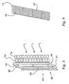
- a flow body extending along the longitudinal axis is arranged inside the tube.
- This is formed by a strip of material which is helically twisted about its longitudinal axis.
- This flow body advantageously extends through the entire support frame and the entire tube and is arranged approximately centrally in cross section. The flow body causes the turbulent incoming water to be diverted from this due to the helical shape in another flow direction and rectified. This in turn means that the penetrating into the cavity water can be controlled and discharged faster.
- the filter element is particularly suitable for use in a filter wall, which can be set in a flowing water and this filter.
- the filter wall is formed from an example frame-like support structure, which may be covered by a cover.
- In the support structure or in the cover are openings in which the tubes of the filter elements can be inserted.
- a plurality of filter elements can be plugged into such a support structure side by side.
- a clamping attachment in the support structure is sufficient, but it may also be advantageous to equip the tubes, for example, with a thread that is then screwed into the opening.
- These can also be attached to the back of the cover by means of a screw or a split pin.
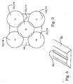
- a layer of filter elements with relatively short tubes and another layer of filter elements To form with relatively long tubes that are arranged in alternation.
- the filter elements with short tubes matrix so be arranged side by side in the manner of a checkerboard pattern.
- a relatively large clearance is created in the middle of four filter elements.
- the distance between the four filter elements to each other is such that a tube of a filter element with a long tube between the four filter bodies can extend through into an opening of the support structure.
- Measurements have shown that up to 250 l per second per square meter can be passed and filtered through a filter wall according to the invention.
- the measurements were carried out with a filter wall with 98 filter elements at a flow level about one meter wide and 5 cm high.
- the flow rate is so high, among other things, because behind the filter elements after a certain time a suction occurs.
- the filter wall can be kept in the flowing water by any suitable device.
- a foot body is provided, which is placed on the bottom of the bed of flowing water and having a groove into which an outer side of the support structure is used.
- the use of the filter element according to the invention in a filter wall poses no danger to living beings and fish. It is absolutely impermeable to elongated solids such as algae or the like, so that underlying plant components, such as a turbine or a water wheel are effectively protected.
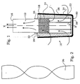
- a filter element 10 has a tube 12 and a filter body 14.
- the tube 12 and the filter body 14 are preferably cylindrical and arranged concentrically about a longitudinal axis X-X.
- the tube 12 has a free end 16 and a filter body side end 18.
- a support frame 20 is attached. This may be formed of bars 22 which are covered by a network structure. As a network structure, for example, a grid 24, but also a stocking can be provided. Within the support frame 20, a cavity is formed.
- the support frame 20 is surrounded by a base layer 26 which is connected to the support frame 20.
- An outer layer 28 which is connected to the base layer is in turn arranged around the base layer 26.
- Both the base layer 26 and the outer layer 28 may include epoxy resin as the bonding and bonding agent.
- Epoxy resin can be any other suitable adhesive or binder, depending after use, however, care must be taken to ensure that it does not secrete any toxins.
- the filter body 14 has an end face 30 and a rear side 32.
- the back 32 is not covered by the outer layer 28 in the present embodiment, the back 32 may be either impermeable or covered with the outer layer 28.
- the rods 22 are advantageously connected to each other by transverse bars 34 at the ends facing away from the tube 12.
- the lattice 24 is shown only partially in FIG. 1, it extends over the entire length of the rods 22.
- the rods 22 protrude from the rear side 32 of the filter body 14, and this too is to be understood only as an example, also other fastening possibilities for the filter body are conceivable.
- the illustrated arrows illustrate that the liquid from the outside can penetrate from all sides through the outer layer 28 and the base layer 26 into the cavity of the support frame 20 and can be discharged through the tube 12.
- Figure 2 shows a helical flow body 36 which can be used in a particularly advantageous embodiment in the hollow body of the support frame 20 and in the tube 12 and fastened in this.
- the flow body 36 is connected to an inner bottom 38 of the filter body 14 and has the task of controlling the swirling liquid quantities controlled by diverting in a rectified flow.
- FIG. 3 illustrates the use of filter elements 10 according to the invention in a filter wall 38.
- the latter has a front side 40 opposite the flow and an opposite rear side 42.
- the flow is again represented by arrows.
- the filter wall 38 consists essentially of a support structure 44 (see also Figure 4), in which the filter elements 10 are used.
- the support structure 44 may have on its back 42 support members 48, with which the filter wall can be kept in the flowing water.
- the filter elements 10 are inserted with their tubes 12 in the openings 46 and attached depending on the application by means of a thread or cotter pin.
- the liquid thus flows through the filter body 14 and the tubes 12 and thus passes from the front side 40 to the back 42 of the support structure 44th
- FIG. 3 furthermore illustrates an advantageous embodiment of a filter wall 38 in that filter elements 10 with long tubes 12 and filter elements 10 with shorter tubes 12 are provided.
- the filter elements 10 are arranged such that, in principle, two layers result, namely a front and a back layer.
- the filter elements 10 may be arbitrarily arranged to form these two layers, but FIG. 5 illustrates an advantageous arrangement possibility.
- a filter element 10 with a long tube 12 is arranged centrally.
- the filter body 14 of the filter elements 10 with a long tube 12 spaced from the filter bodies 14 of the filter elements 10 may be arranged with short tube 12, but they can also be postponed until contact.
- the support structure 44 can be covered by a front cover, not shown here, wherein the cover has circular openings for receiving the tubes 12.
- a front cover not shown here, wherein the cover has circular openings for receiving the tubes 12.
- FIG. 6 shows a foot body 50 for receiving the support structure 44.
- the foot body 50 has a longitudinal groove 52, into which a lower transverse edge 54 of the support structure 44 can be inserted.
- the foot 50 is placed on the bottom of the water-bearing channel or river.
- the support members 48 may then be omitted, but they may also remain as additional additional support.
- a significant advantage of the filter wall 38 according to the invention is also that the filter elements 10 can be quickly and easily serviced or replaced.
Landscapes
- Chemical & Material Sciences (AREA)
- Chemical Kinetics & Catalysis (AREA)
- Inorganic Chemistry (AREA)
- Engineering & Computer Science (AREA)
- Ceramic Engineering (AREA)
- Life Sciences & Earth Sciences (AREA)
- Geology (AREA)
- Filtering Materials (AREA)
- Filtration Of Liquid (AREA)
- Separation Using Semi-Permeable Membranes (AREA)
Claims (12)
- Elément filtrant allongé (10) pour retenir des matières grossières dans un liquide courant, comprenant- un tuyau (12) qui est relié à- un corps creux de filtration (14) qui est formé- d'un cadre porteur (20) disposé à l'intérieur, formant un espace creux et relié audit tuyau (12),- d'une couche de base (26) en une matière à grains relativement gros qui entoure ledit cadre porteur (20) et est reliée à celui-ci,- d'une couche extérieure (28) en une matière à grains relativement fins qui entoure ladite couche de base (26) et est reliée à celle-ci,- de sorte que le liquide peut s'écouler de l'extérieur dans ledit corps de filtration (14) et puis à travers ledit tuyau (12).
- Elément filtrant allongé (10) selon la revendication 1, caractérisé par le fait que ladite couche de base (26) est réalisée en gravillon ayant une granulométrie comprise entre 3 mm et 10 mm, de préférence entre 6 mm et 8 mm et que ladite couche extérieure est réalisée dans une matière granuleuse ayant une granulométrie inférieure à 2 mm, de préférence comprise entre 0,3 mm et 1,3 mm.
- Elément filtrant allongé (10) selon la revendication 1 ou la revendication 2, caractérisé par le fait que le rapport des épaisseurs de couche de la couche extérieure (28) et de la couche de base (26) est de 1 à 3 à peu près.
- Elément filtrant allongé (10) selon l'une des revendications 1 à 3, caractérisé par le fait que dans l'espace creux du cadre porteur est disposé un corps d'écoulement (36) qui s'étend jusque dans ledit tuyau (12) et qui dérive les écoulements turbulents du liquide affluent de manière à obtenir un écoulement dirigé dans la même direction.
- Elément filtrant allongé (10) selon l'une des revendications 1 à 4, caractérisé par le fait que ledit cadre porteur est formé de barres (22) qui, à l'extrémité, sont reliées à une extrémité libre du tuyau (12) et qui sont entourées d'un filet en treillis (24).
- Elément filtrant allongé (10) selon l'une des revendications 1 à 5, caractérisé par le fait que ledit corps de filtration (14) est réalisé de manière à être pour l'essentiel cylindrique.
- Utilisation d ' un élément filtrant allongé (10) selon l'une des revendications 1 à 6 dans une paroi filtrante (38) destinée à être mise en place dans un liquide courant, ladite paroi filtrante (38) présentant- une construction porteuse (44) ayant une face avant (40) opposée au sens d'écoulement du liquide lorsqu'elle est mise en place ainsi qu'une face arrière (42), et- des ouvertures (46) dans chacune d'elles est introduit un tuyau (12) de l'élément filtrant (10).
- Utilisation d'un élément filtrant allongé (10) dans une paroi filtrante (38) selon la revendication 7, caractérisée par le fait que la face avant (40) de la paroi filtrante (38) est recouverte en surface par une couverture, ladite couverture présentant des ouvertures circulaires dans chacune d'elles peut être introduit un tuyau (12) d'un élément filtrant (10).
- Utilisation d'un élément filtrant allongé (10) dans une paroi filtrante (38) selon la revendication 7 ou 8, caractérisée par le fait que dans lesdites ouvertures (46) de la paroi filtrante (38) sont introduits les éléments filtrants (10) ayant des tuyaux (12) de longueurs différentes, de sorte que, en coupe transversale de la paroi filtrante (38), est réalisée une couche avant de corps de filtration (14) et une couche arrière de corps de filtration (14).
- Utilisation d'un élément filtrant allongé (10) dans une paroi filtrante (38) selon la revendication 9, caractérisée par le fait que les éléments filtrants (10) sont aménagés dans la paroi filtrante (38) de telle manière que respectivement un tuyau long (12) s'étend entre quatre corps de filtration (14) d'éléments filtrants (10) de la couche arrière dans une ouverture (46).
- Utilisation d'un élément filtrant allongé (10) dans une paroi filtrante (38) selon l'une des revendications 7 à 10, caractérisée par le fait que lesdits éléments filtrants (10) sont fixés de manière amovible sur ladite construction porteuse (44).
- Utilisation d'un élément filtrant allongé (10) dans une paroi filtrante (38) selon l'une des revendications 7 à 11, caractérisée par le fait que sur ladite paroi filtrante (38) est prévu un corps formant pied (50) présentant une rainure (52) dans laquelle ladite construction porteuse (44) peut être placée avec une arête transversale (54) et y est maintenue.
Applications Claiming Priority (2)
| Application Number | Priority Date | Filing Date | Title |
|---|---|---|---|
| DE10352937A DE10352937B3 (de) | 2003-11-11 | 2003-11-11 | Filterelement für das Zurückhalten von Grobstoffen in einer fließenden Flüssigkeit |
| DE10352937 | 2003-11-11 |
Publications (3)
| Publication Number | Publication Date |
|---|---|
| EP1530992A2 EP1530992A2 (fr) | 2005-05-18 |
| EP1530992A3 EP1530992A3 (fr) | 2005-08-03 |
| EP1530992B1 true EP1530992B1 (fr) | 2007-11-28 |
Family
ID=34428704
Family Applications (1)
| Application Number | Title | Priority Date | Filing Date |
|---|---|---|---|
| EP04022628A Expired - Lifetime EP1530992B1 (fr) | 2003-11-11 | 2004-09-23 | Elément filtrant pour retenir les contaminants grossiers d'un liquide en écoulement |
Country Status (2)
| Country | Link |
|---|---|
| EP (1) | EP1530992B1 (fr) |
| DE (2) | DE10352937B3 (fr) |
Families Citing this family (1)
| Publication number | Priority date | Publication date | Assignee | Title |
|---|---|---|---|---|
| CN113789843A (zh) * | 2021-09-18 | 2021-12-14 | 同济大学建筑设计研究院(集团)有限公司 | 一种用于合流制排渠内的一体化截流装置 |
Citations (1)
| Publication number | Priority date | Publication date | Assignee | Title |
|---|---|---|---|---|
| US5290457A (en) * | 1989-12-29 | 1994-03-01 | Seitz-Filter-Werke Gmbh & Co. | Filter element with regenerable bulk material filling and method for making same |
Family Cites Families (10)
| Publication number | Priority date | Publication date | Assignee | Title |
|---|---|---|---|---|
| GB786570A (en) * | 1955-01-26 | 1957-11-20 | Paterson Engineering Company L | Improved filter for liquids |
| US4629483A (en) * | 1986-01-06 | 1986-12-16 | Refractron Corp. | Ceramic filter with plural layers of different porosity |
| DE4243932C2 (de) * | 1992-12-23 | 1999-06-10 | T Z Entwicklungs & Handelsgese | Schutzgitter für Freispiegelgerinne |
| DE19533935C2 (de) * | 1994-09-20 | 1998-09-24 | Patrick Blaase | Vorrichtung für die Reinigung von Abwasser |
| CN1147210A (zh) * | 1994-12-27 | 1997-04-09 | 有限会社米卡子基文化会馆 | 多孔陶瓷过滤器、其制造方法及多孔陶瓷过滤器制造用挤出成型模具和使用该模具的挤出成型装置 |
| DE19515924A1 (de) * | 1995-05-02 | 1995-10-05 | Umwelttechnik & Anlagenbau Gmb | Feinrechen mit Reinigungseinrichtung |
| CA2190238A1 (fr) * | 1996-07-15 | 1998-01-15 | Ryutaro Motoki | Filtres de metal fritte |
| DE19714089A1 (de) * | 1997-04-07 | 1998-10-08 | Manfred Huetten | Filterstufenrechen |
| GB9825489D0 (en) * | 1998-11-21 | 1999-01-13 | Fairey Microfiltrex Limited | Filter elements |
| DE10100098A1 (de) * | 2000-12-07 | 2002-06-13 | Alexander Von Koeckritz | Rechen für wasserbauliche Anlagen |
-
2003
- 2003-11-11 DE DE10352937A patent/DE10352937B3/de not_active Expired - Fee Related
-
2004
- 2004-09-23 EP EP04022628A patent/EP1530992B1/fr not_active Expired - Lifetime
- 2004-09-23 DE DE502004005597T patent/DE502004005597D1/de not_active Expired - Lifetime
Patent Citations (1)
| Publication number | Priority date | Publication date | Assignee | Title |
|---|---|---|---|---|
| US5290457A (en) * | 1989-12-29 | 1994-03-01 | Seitz-Filter-Werke Gmbh & Co. | Filter element with regenerable bulk material filling and method for making same |
Also Published As
| Publication number | Publication date |
|---|---|
| EP1530992A2 (fr) | 2005-05-18 |
| DE502004005597D1 (de) | 2008-01-10 |
| DE10352937B3 (de) | 2005-06-02 |
| EP1530992A3 (fr) | 2005-08-03 |
Similar Documents
| Publication | Publication Date | Title |
|---|---|---|
| DE2852108A1 (de) | Rohrbrunnenfilter | |
| DE60218026T2 (de) | Verfahren zum filtern von schwimmbecken mit verstärker der wasserdurchflussmenge | |
| DE102010037223B4 (de) | Wasserfassung | |
| EP2508686B1 (fr) | Installation de retenue pour l'eau de précipitation et les eaux usées | |
| EP1530992B1 (fr) | Elément filtrant pour retenir les contaminants grossiers d'un liquide en écoulement | |
| DE3045740C2 (de) | Vorrichtung zum Rückgewinnen von Wärme | |
| EP1702661B1 (fr) | Méthode pour purifier l'eau avec un tricot filtrant | |
| DE19916964C2 (de) | Rückhalteanlage für Niederschlagswasser und Abwasser | |
| DE1800852A1 (de) | Filterstrang fuer Rohrbrunnen | |
| EP2363185B1 (fr) | Elément de filtre pouvant être régénéré et doté de couches de support | |
| DE68902618T2 (de) | Pumpenanlage, insbesondere fuer bewaesserung. | |
| DE102013107153A1 (de) | Reinigungsschacht sowie Verfahren zur dezentralen Regenwasserbehandlung | |
| EP1038436B1 (fr) | Dispositif à filtrer un plan d'eau | |
| DE9413754U1 (de) | Ansaugfilter für eine Teichpumpe | |
| DE102005019190B4 (de) | Ablaufkörper | |
| DE10221968A1 (de) | Aufnahmevorrichtung für Trocknungsmittel | |
| DE10100098A1 (de) | Rechen für wasserbauliche Anlagen | |
| DE29922729U1 (de) | Filtersystem für Teichanlagen | |
| DE29901537U1 (de) | Filtervorrichtung eines Gewässers | |
| EP3805474B1 (fr) | Dispositif d'étranglement à turbulence | |
| DE1969143U (de) | Filtriervorrichtung. | |
| DE2626139B1 (de) | Abflussleitungssystem fuer sanitaere anlagen | |
| AT396462B (de) | Verfahren und anlage zum versickern von abwasser | |
| DE20105479U1 (de) | Rückhalteanlage | |
| BE903486A (fr) | Verfahren zur wasserenthnahme sowie wasserentnahmeanordnung |
Legal Events
| Date | Code | Title | Description |
|---|---|---|---|
| PUAI | Public reference made under article 153(3) epc to a published international application that has entered the european phase |
Free format text: ORIGINAL CODE: 0009012 |
|
| AK | Designated contracting states |
Kind code of ref document: A2 Designated state(s): AT BE BG CH CY CZ DE DK EE ES FI FR GB GR HU IE IT LI LU MC NL PL PT RO SE SI SK TR |
|
| AX | Request for extension of the european patent |
Extension state: AL HR LT LV MK |
|
| PUAL | Search report despatched |
Free format text: ORIGINAL CODE: 0009013 |
|
| AK | Designated contracting states |
Kind code of ref document: A3 Designated state(s): AT BE BG CH CY CZ DE DK EE ES FI FR GB GR HU IE IT LI LU MC NL PL PT RO SE SI SK TR |
|
| AX | Request for extension of the european patent |
Extension state: AL HR LT LV MK |
|
| 17P | Request for examination filed |
Effective date: 20060203 |
|
| AKX | Designation fees paid |
Designated state(s): AT BE BG CH CY CZ DE DK EE ES FI FR GB GR HU IE IT LI LU MC NL PL PT RO SE SI SK TR |
|
| 17Q | First examination report despatched |
Effective date: 20060712 |
|
| GRAP | Despatch of communication of intention to grant a patent |
Free format text: ORIGINAL CODE: EPIDOSNIGR1 |
|
| GRAS | Grant fee paid |
Free format text: ORIGINAL CODE: EPIDOSNIGR3 |
|
| GRAA | (expected) grant |
Free format text: ORIGINAL CODE: 0009210 |
|
| AK | Designated contracting states |
Kind code of ref document: B1 Designated state(s): AT BE BG CH CY CZ DE DK EE ES FI FR GB GR HU IE IT LI LU MC NL PL PT RO SE SI SK TR |
|
| REG | Reference to a national code |
Ref country code: GB Ref legal event code: FG4D Free format text: NOT ENGLISH |
|
| REG | Reference to a national code |
Ref country code: IE Ref legal event code: FG4D Free format text: LANGUAGE OF EP DOCUMENT: GERMAN |
|
| REG | Reference to a national code |
Ref country code: CH Ref legal event code: EP |
|
| REF | Corresponds to: |
Ref document number: 502004005597 Country of ref document: DE Date of ref document: 20080110 Kind code of ref document: P |
|
| RAP2 | Party data changed (patent owner data changed or rights of a patent transferred) |
Owner name: BLOMEIER, MAXIMILIAN |
|
| RIN2 | Information on inventor provided after grant (corrected) |
Inventor name: BLOMEIER, MAXIMILIAN |
|
| NLT2 | Nl: modifications (of names), taken from the european patent patent bulletin |
Owner name: BLOMEIER, MAXIMILIAN Effective date: 20080213 |
|
| PG25 | Lapsed in a contracting state [announced via postgrant information from national office to epo] |
Ref country code: ES Free format text: LAPSE BECAUSE OF FAILURE TO SUBMIT A TRANSLATION OF THE DESCRIPTION OR TO PAY THE FEE WITHIN THE PRESCRIBED TIME-LIMIT Effective date: 20080311 Ref country code: SE Free format text: LAPSE BECAUSE OF FAILURE TO SUBMIT A TRANSLATION OF THE DESCRIPTION OR TO PAY THE FEE WITHIN THE PRESCRIBED TIME-LIMIT Effective date: 20080228 Ref country code: NL Free format text: LAPSE BECAUSE OF FAILURE TO SUBMIT A TRANSLATION OF THE DESCRIPTION OR TO PAY THE FEE WITHIN THE PRESCRIBED TIME-LIMIT Effective date: 20071128 |
|
| NLV1 | Nl: lapsed or annulled due to failure to fulfill the requirements of art. 29p and 29m of the patents act | ||
| PG25 | Lapsed in a contracting state [announced via postgrant information from national office to epo] |
Ref country code: SI Free format text: LAPSE BECAUSE OF FAILURE TO SUBMIT A TRANSLATION OF THE DESCRIPTION OR TO PAY THE FEE WITHIN THE PRESCRIBED TIME-LIMIT Effective date: 20071128 Ref country code: FI Free format text: LAPSE BECAUSE OF FAILURE TO SUBMIT A TRANSLATION OF THE DESCRIPTION OR TO PAY THE FEE WITHIN THE PRESCRIBED TIME-LIMIT Effective date: 20071128 Ref country code: BG Free format text: LAPSE BECAUSE OF FAILURE TO SUBMIT A TRANSLATION OF THE DESCRIPTION OR TO PAY THE FEE WITHIN THE PRESCRIBED TIME-LIMIT Effective date: 20080228 Ref country code: PL Free format text: LAPSE BECAUSE OF FAILURE TO SUBMIT A TRANSLATION OF THE DESCRIPTION OR TO PAY THE FEE WITHIN THE PRESCRIBED TIME-LIMIT Effective date: 20071128 |
|
| PG25 | Lapsed in a contracting state [announced via postgrant information from national office to epo] |
Ref country code: DK Free format text: LAPSE BECAUSE OF FAILURE TO SUBMIT A TRANSLATION OF THE DESCRIPTION OR TO PAY THE FEE WITHIN THE PRESCRIBED TIME-LIMIT Effective date: 20071128 Ref country code: CZ Free format text: LAPSE BECAUSE OF FAILURE TO SUBMIT A TRANSLATION OF THE DESCRIPTION OR TO PAY THE FEE WITHIN THE PRESCRIBED TIME-LIMIT Effective date: 20071128 |
|
| PG25 | Lapsed in a contracting state [announced via postgrant information from national office to epo] |
Ref country code: SK Free format text: LAPSE BECAUSE OF FAILURE TO SUBMIT A TRANSLATION OF THE DESCRIPTION OR TO PAY THE FEE WITHIN THE PRESCRIBED TIME-LIMIT Effective date: 20071128 Ref country code: RO Free format text: LAPSE BECAUSE OF FAILURE TO SUBMIT A TRANSLATION OF THE DESCRIPTION OR TO PAY THE FEE WITHIN THE PRESCRIBED TIME-LIMIT Effective date: 20071128 |
|
| EN | Fr: translation not filed | ||
| PG25 | Lapsed in a contracting state [announced via postgrant information from national office to epo] |
Ref country code: PT Free format text: LAPSE BECAUSE OF FAILURE TO SUBMIT A TRANSLATION OF THE DESCRIPTION OR TO PAY THE FEE WITHIN THE PRESCRIBED TIME-LIMIT Effective date: 20080428 |
|
| REG | Reference to a national code |
Ref country code: IE Ref legal event code: FD4D |
|
| PLBE | No opposition filed within time limit |
Free format text: ORIGINAL CODE: 0009261 |
|
| STAA | Information on the status of an ep patent application or granted ep patent |
Free format text: STATUS: NO OPPOSITION FILED WITHIN TIME LIMIT |
|
| PG25 | Lapsed in a contracting state [announced via postgrant information from national office to epo] |
Ref country code: IE Free format text: LAPSE BECAUSE OF FAILURE TO SUBMIT A TRANSLATION OF THE DESCRIPTION OR TO PAY THE FEE WITHIN THE PRESCRIBED TIME-LIMIT Effective date: 20071128 Ref country code: FR Free format text: LAPSE BECAUSE OF FAILURE TO SUBMIT A TRANSLATION OF THE DESCRIPTION OR TO PAY THE FEE WITHIN THE PRESCRIBED TIME-LIMIT Effective date: 20080912 |
|
| REG | Reference to a national code |
Ref country code: FR Ref legal event code: RN |
|
| 26N | No opposition filed |
Effective date: 20080829 |
|
| REG | Reference to a national code |
Ref country code: FR Ref legal event code: FC |
|
| ET | Fr: translation filed | ||
| PG25 | Lapsed in a contracting state [announced via postgrant information from national office to epo] |
Ref country code: GR Free format text: LAPSE BECAUSE OF FAILURE TO SUBMIT A TRANSLATION OF THE DESCRIPTION OR TO PAY THE FEE WITHIN THE PRESCRIBED TIME-LIMIT Effective date: 20080229 |
|
| BERE | Be: lapsed |
Owner name: BLOMEIER, MAXIMILIAN Effective date: 20080930 Owner name: LULSDORF, DETLEF Effective date: 20080930 Owner name: SAUER, MARKUS Effective date: 20080930 Owner name: WILHELMY, KARL-HEINZ Effective date: 20080930 |
|
| PG25 | Lapsed in a contracting state [announced via postgrant information from national office to epo] |
Ref country code: EE Free format text: LAPSE BECAUSE OF FAILURE TO SUBMIT A TRANSLATION OF THE DESCRIPTION OR TO PAY THE FEE WITHIN THE PRESCRIBED TIME-LIMIT Effective date: 20071128 Ref country code: MC Free format text: LAPSE BECAUSE OF NON-PAYMENT OF DUE FEES Effective date: 20080930 |
|
| REG | Reference to a national code |
Ref country code: CH Ref legal event code: PL |
|
| PG25 | Lapsed in a contracting state [announced via postgrant information from national office to epo] |
Ref country code: BE Free format text: LAPSE BECAUSE OF NON-PAYMENT OF DUE FEES Effective date: 20080930 Ref country code: CY Free format text: LAPSE BECAUSE OF FAILURE TO SUBMIT A TRANSLATION OF THE DESCRIPTION OR TO PAY THE FEE WITHIN THE PRESCRIBED TIME-LIMIT Effective date: 20071128 |
|
| PG25 | Lapsed in a contracting state [announced via postgrant information from national office to epo] |
Ref country code: IT Free format text: LAPSE BECAUSE OF NON-PAYMENT OF DUE FEES Effective date: 20080923 |
|
| PG25 | Lapsed in a contracting state [announced via postgrant information from national office to epo] |
Ref country code: AT Free format text: LAPSE BECAUSE OF NON-PAYMENT OF DUE FEES Effective date: 20080923 Ref country code: LI Free format text: LAPSE BECAUSE OF NON-PAYMENT OF DUE FEES Effective date: 20080930 Ref country code: CH Free format text: LAPSE BECAUSE OF NON-PAYMENT OF DUE FEES Effective date: 20080930 |
|
| PG25 | Lapsed in a contracting state [announced via postgrant information from national office to epo] |
Ref country code: HU Free format text: LAPSE BECAUSE OF FAILURE TO SUBMIT A TRANSLATION OF THE DESCRIPTION OR TO PAY THE FEE WITHIN THE PRESCRIBED TIME-LIMIT Effective date: 20080529 Ref country code: LU Free format text: LAPSE BECAUSE OF NON-PAYMENT OF DUE FEES Effective date: 20080923 |
|
| PG25 | Lapsed in a contracting state [announced via postgrant information from national office to epo] |
Ref country code: TR Free format text: LAPSE BECAUSE OF FAILURE TO SUBMIT A TRANSLATION OF THE DESCRIPTION OR TO PAY THE FEE WITHIN THE PRESCRIBED TIME-LIMIT Effective date: 20071128 |
|
| PGFP | Annual fee paid to national office [announced via postgrant information from national office to epo] |
Ref country code: FR Payment date: 20111005 Year of fee payment: 8 Ref country code: GB Payment date: 20110923 Year of fee payment: 8 |
|
| GBPC | Gb: european patent ceased through non-payment of renewal fee |
Effective date: 20120923 |
|
| REG | Reference to a national code |
Ref country code: FR Ref legal event code: ST Effective date: 20130531 |
|
| PG25 | Lapsed in a contracting state [announced via postgrant information from national office to epo] |
Ref country code: GB Free format text: LAPSE BECAUSE OF NON-PAYMENT OF DUE FEES Effective date: 20120923 |
|
| PG25 | Lapsed in a contracting state [announced via postgrant information from national office to epo] |
Ref country code: FR Free format text: LAPSE BECAUSE OF NON-PAYMENT OF DUE FEES Effective date: 20121001 |
|
| PGFP | Annual fee paid to national office [announced via postgrant information from national office to epo] |
Ref country code: DE Payment date: 20150216 Year of fee payment: 11 |
|
| REG | Reference to a national code |
Ref country code: DE Ref legal event code: R119 Ref document number: 502004005597 Country of ref document: DE |
|
| PG25 | Lapsed in a contracting state [announced via postgrant information from national office to epo] |
Ref country code: DE Free format text: LAPSE BECAUSE OF NON-PAYMENT OF DUE FEES Effective date: 20160401 |