EP1530681B1 - Fuel injection device for an internal combustion engine - Google Patents
Fuel injection device for an internal combustion engine Download PDFInfo
- Publication number
- EP1530681B1 EP1530681B1 EP03720202A EP03720202A EP1530681B1 EP 1530681 B1 EP1530681 B1 EP 1530681B1 EP 03720202 A EP03720202 A EP 03720202A EP 03720202 A EP03720202 A EP 03720202A EP 1530681 B1 EP1530681 B1 EP 1530681B1
- Authority
- EP
- European Patent Office
- Prior art keywords
- fuel
- internal combustion
- combustion engine
- pressure pumps
- high pressure
- Prior art date
- Legal status (The legal status is an assumption and is not a legal conclusion. Google has not performed a legal analysis and makes no representation as to the accuracy of the status listed.)
- Expired - Lifetime
Links
Images
Classifications
-
- F—MECHANICAL ENGINEERING; LIGHTING; HEATING; WEAPONS; BLASTING
- F02—COMBUSTION ENGINES; HOT-GAS OR COMBUSTION-PRODUCT ENGINE PLANTS
- F02M—SUPPLYING COMBUSTION ENGINES IN GENERAL WITH COMBUSTIBLE MIXTURES OR CONSTITUENTS THEREOF
- F02M63/00—Other fuel-injection apparatus having pertinent characteristics not provided for in groups F02M39/00 - F02M57/00 or F02M67/00; Details, component parts, or accessories of fuel-injection apparatus, not provided for in, or of interest apart from, the apparatus of groups F02M39/00 - F02M61/00 or F02M67/00; Combination of fuel pump with other devices, e.g. lubricating oil pump
- F02M63/02—Fuel-injection apparatus having several injectors fed by a common pumping element, or having several pumping elements feeding a common injector; Fuel-injection apparatus having provisions for cutting-out pumps, pumping elements, or injectors; Fuel-injection apparatus having provisions for variably interconnecting pumping elements and injectors alternatively
- F02M63/0225—Fuel-injection apparatus having a common rail feeding several injectors ; Means for varying pressure in common rails; Pumps feeding common rails
-
- F—MECHANICAL ENGINEERING; LIGHTING; HEATING; WEAPONS; BLASTING
- F02—COMBUSTION ENGINES; HOT-GAS OR COMBUSTION-PRODUCT ENGINE PLANTS
- F02M—SUPPLYING COMBUSTION ENGINES IN GENERAL WITH COMBUSTIBLE MIXTURES OR CONSTITUENTS THEREOF
- F02M59/00—Pumps specially adapted for fuel-injection and not provided for in groups F02M39/00 -F02M57/00, e.g. rotary cylinder-block type of pumps
- F02M59/20—Varying fuel delivery in quantity or timing
- F02M59/34—Varying fuel delivery in quantity or timing by throttling of passages to pumping elements or of overflow passages, e.g. throttling by means of a pressure-controlled sliding valve having liquid stop or abutment
-
- F—MECHANICAL ENGINEERING; LIGHTING; HEATING; WEAPONS; BLASTING
- F02—COMBUSTION ENGINES; HOT-GAS OR COMBUSTION-PRODUCT ENGINE PLANTS
- F02M—SUPPLYING COMBUSTION ENGINES IN GENERAL WITH COMBUSTIBLE MIXTURES OR CONSTITUENTS THEREOF
- F02M63/00—Other fuel-injection apparatus having pertinent characteristics not provided for in groups F02M39/00 - F02M57/00 or F02M67/00; Details, component parts, or accessories of fuel-injection apparatus, not provided for in, or of interest apart from, the apparatus of groups F02M39/00 - F02M61/00 or F02M67/00; Combination of fuel pump with other devices, e.g. lubricating oil pump
- F02M63/02—Fuel-injection apparatus having several injectors fed by a common pumping element, or having several pumping elements feeding a common injector; Fuel-injection apparatus having provisions for cutting-out pumps, pumping elements, or injectors; Fuel-injection apparatus having provisions for variably interconnecting pumping elements and injectors alternatively
- F02M63/0225—Fuel-injection apparatus having a common rail feeding several injectors ; Means for varying pressure in common rails; Pumps feeding common rails
- F02M63/023—Means for varying pressure in common rails
- F02M63/0235—Means for varying pressure in common rails by bleeding fuel pressure
- F02M63/025—Means for varying pressure in common rails by bleeding fuel pressure from the common rail
-
- F—MECHANICAL ENGINEERING; LIGHTING; HEATING; WEAPONS; BLASTING
- F02—COMBUSTION ENGINES; HOT-GAS OR COMBUSTION-PRODUCT ENGINE PLANTS
- F02M—SUPPLYING COMBUSTION ENGINES IN GENERAL WITH COMBUSTIBLE MIXTURES OR CONSTITUENTS THEREOF
- F02M37/00—Apparatus or systems for feeding liquid fuel from storage containers to carburettors or fuel-injection apparatus; Arrangements for purifying liquid fuel specially adapted for, or arranged on, internal-combustion engines
- F02M37/0047—Layout or arrangement of systems for feeding fuel
Definitions
- the invention relates to a fuel injection device for an internal combustion engine according to the preamble of claim 1.
- Such a fuel injection device is characterized by the US 5,404,855 A known.
- This fuel injection device has at least one high-pressure pump, is conveyed by the fuel in a memory and having a driven by a camshaft in a reciprocating pump piston.
- a feed pump fuel is conveyed from a fuel reservoir to the at least one high-pressure pump.
- a fuel metering device is arranged, through which the inflow of fuel from the feed pump to the at least one high pressure pump is adjusted such that by the at least one high-pressure pump, an amount of fuel is fed into the memory, which is required in memory to maintain a predetermined pressure.
- the camshaft is a separate camshaft of the high pressure pump, whereby the high pressure pump requires a large manufacturing effort and also a drive for the camshaft of the high pressure pump must be provided by the internal combustion engine.
- a fuel injection device for an internal combustion engine which has at least one high-pressure pump which has a pump piston driven by a camshaft of the internal combustion engine, so that the high-pressure pump does not need its own camshaft.
- a solenoid valve is provided on each high-pressure pump through which communication with a relief region is controlled, thereby controlling the amount of fuel delivered into the reservoir by the high-pressure pumps. Due to the solenoid valve, the high-pressure pump has a complex and construction and a large size, so that their arrangement is difficult on the internal combustion engine.
- a solenoid valve is required, which increases the fuel injector considerably.
- the fuel injection device according to the invention with the features of claim 1 has the advantage that no separate camshaft is required for the multiple high-pressure pumps and that this has a compact and simple structure and thus can be easily attached to the engine.
- the fuel injector is simple and inexpensive.
- the embodiment according to claim 4 ensures that the pressure between the feed pump and the fuel metering device is limited when no or only a small inflow of fuel is adjusted by the fuel metering device.
- the embodiment according to claim 5 ensures that no fuel is conveyed through the plurality of high-pressure pumps, which is necessary in certain operating conditions of the internal combustion engine, even if the inflow of fuel can not be completely prevented by the fuel metering device.
- the embodiment according to claim 7 allows even with a small number of high-pressure pumps uniform fuel delivery in the memory.
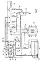
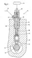
- FIG. 1 shows a fuel injection device for an internal combustion engine in a schematic representation and Figure 2 shows a detail of the fuel injection device in a section along line II-II in Figure 1.
- FIGS. 1 and 2 show a fuel injection device for an internal combustion engine, for example of a motor vehicle.
- the internal combustion engine is preferably a self-igniting internal combustion engine and has one or more cylinders.
- the motor vehicle has a fuel tank 10, is stored in the fuel for the operation of the internal combustion engine.
- the fuel injection device has a feed pump 12, is conveyed by the fuel from the fuel tank 10 via a connection 13 to the suction side of several, for example, two high-pressure pumps 14.
- the high pressure pumps 14 deliver fuel into a reservoir 16 which may be tubular, for example, or in any other form. From the memory 16 lead lines 18 to arranged on the cylinders of the internal combustion engine injectors 20 from.
- an electric control valve 22 through which an opening of the injectors 20 is controlled so as to effect fuel injection by the respective injector 20 or prevent fuel injection.
- the control valves 22 are controlled by an electronic control device 23, is determined by the function of operating parameters of the internal combustion engine, such as speed, load, temperature and others, the timing and duration of the fuel injection by the injectors 20.
- the high-pressure pumps 14 are mechanically driven by a camshaft 30 of the internal combustion engine and thus proportional to the speed of the internal combustion engine.
- the high-pressure pumps 14 each have a pump housing 32, in which in a cylinder bore 34, a pump piston 36 is tightly guided, which limits a pump working space 38 in the respective cylinder bore 34.
- an outlet valve 40 is arranged in the form of a check valve 16 opening towards the reservoir 16, through which the separation between the pump working chambers 38 and the reservoir 16 takes place during the suction stroke of the pump piston 36.
- an inlet valve 42 in the form of a pump working spaces 38 toward the opening check valve is arranged, through which the separation between the pump working chambers 38 and the feed pump 12 during the delivery stroke of the pump piston 36 ,
- the pump pistons 36 of the high-pressure pumps 14 are driven directly by the camshaft 30 of the internal combustion engine, through which the gas exchange valves of the internal combustion engine are actuated.
- the camshaft 30 in this case has additional cams 44 corresponding to the number of high-pressure pumps 14, through which the pump pistons 36 are driven in a stroke movement.
- the cams 44 are preferably designed as multiple cams, for example as shown in Figure 2 as a triple cam, so that each pump piston 36 executes three strokes in one revolution of the camshaft 30. In the case of two high-pressure pumps 14, six delivery strokes of the pump pistons 36 thus occur during one revolution of the camshaft 30.
- the fuel injector further includes a fuel metering device 46 disposed between the discharge side of the delivery pump 12 and the suction side of the high pressure pumps 14.
- the fuel metering device 46 is formed for example by an electrically operated proportional valve having an actuator 47, such as an electromagnet or a piezoelectric actuator, and a movable valve member 48 through which a variable flow area is set.
- the actuator 47 is controlled by the control device 23 such that a certain flow area in the connection between the feed pump 12 and the high-pressure pump 14 is adjusted by the valve member 48 of the fuel metering device 46.
- the flow area can be adjusted by the valve member 48 continuously between a maximum flow area and a minimum flow area.
- by the valve member 48 of the flow area are at least approximately completely closed.
- Control device 23 is connected to a pressure sensor 49, by which at least indirectly the pressure prevailing in the memory 16 pressure is detected, and from which an electrical signal for the pressure of the control device 23 is supplied.
- the control device 23 are also supplied with signals for operating conditions of the internal combustion engine from further sensor devices, for example for the rotational speed, the load, the coolant temperature of the internal combustion engine.
- a specific desired value for the pressure in the reservoir 16 is predetermined, wherein a signal for the actual value of the pressure is supplied to the control device 23 by the pressure sensor 49.
- the fuel metering device 46 is actuated by the control device 23 such that this deviation is eliminated.
- the fuel metering device 46 is controlled by the control device 23 such that it sets a larger flow area between the feed pump 12 and the high-pressure pump 14, so that a larger amount of fuel is conveyed into the memory 16 by the high-pressure pumps 14. If the actual value for the pressure in the reservoir 16 is greater than the desired value, then the fuel metering means 46 is controlled by the control device 23 so that it sets a smaller flow area between the feed pump 12 and the high-pressure pump 14, so that by the high-pressure pumps 14 a lower Fuel quantity is conveyed into the memory 16.
- bypass connection 50 which leads to a discharge area, as the example, a fuel tank 10th leading return 54 or the suction side of the feed pump 12 can serve.
- an overflow valve 52 which opens towards the relief region is arranged, which is a pressure valve which opens when a predetermined pressure is exceeded and releases the bypass connection 50 to the relief region.
- the pressure between the feed pump 12 and the fuel metering device 46 increases and if the opening pressure of the overflow valve 52 is exceeded, fuel flows to the discharge area, then that the pressure between the feed pump 12 and the fuel metering device 46 is limited.
- a further bypass connection 56 to a discharge area from ,. as the turn, the return 54 or the suction side of the feed pump 12 can serve.
- a throttle point 58 is provided in the further bypass connection 56. In certain operating conditions of the internal combustion engine, for example, during overrun, may be promoted by the high-pressure pump 14 no fuel in the memory 16. If the flow area between the feed pump 12 and the high-pressure pumps 14 can not be reliably completely closed by the fuel metering device 46, fuel still passes through the fuel metering device 46. This fuel is discharged via the further bypass connection 58 in the discharge area, so that it is not sucked by the high-pressure pumps 14 and conveyed into the memory 16. Through the throttle point 58 the amount of fuel flowing to the discharge area is limited.
- the high-pressure pumps 14 are operatively connected in parallel to each other and these promote fuel independently from each other in the memory 16.
- the high-pressure pumps 14 are in each case an opening 60 of a housing 61, which is a crankcase or a cylinder head of the internal combustion engine used.
- the fuel metering device 46 is arranged separately from the high-pressure pumps 14 as shown in FIG.
- the fuel metering device 46, the bypass connection 50 with the overflow valve 52 and the bypass connection 56 with the throttle restriction 58 can likewise be arranged on the housing of the internal combustion engine, in particular its crankcase or cylinder head.
- the feed pump 12 may have its own drive, for example, an electric motor drive, or driven by the internal combustion engine, for example, also by the camshaft 30.
- a fuel filter 62 may be arranged, which may be formed as a pre-filter can.
- a fuel filter 63 may be arranged, which may be formed as a fine filter.
- a pressure regulating valve 64 by which the pressure in the reservoir 16 can be adjusted by controlling a connection to a relief region through which fuel can be removed from the reservoir 16.
- a pressure relief valve by which the pressure in the memory 16 is limited.
Description
Die Erfindung betrifft eine Kraftstoffeinspritzeinrichtung für eine Brennkraftmaschine nach der Gattung des Anspruchs 1.The invention relates to a fuel injection device for an internal combustion engine according to the preamble of claim 1.
Eine solche Kraftstoffeinspritzeinrichtung ist durch die
Durch die
Die erfindungsgemäße Kraftstoffeinspritzeinrichtung mit den Merkmalen gemäß Anspruch 1 hat demgegenüber den Vorteil, dass für die mehrere Hochdruckpumpen keine eigene Nockenwelle erforderlich ist und dass diese einen kompakten und einfachen Aufbau aufweist und damit auf einfache Weise an der Brennkraftmaschine angebracht werden kann. Bei Verwendung mehrerer Hochdruckpumpen ist dabei nur eine Kraftstoffzumesseinrichtung erforderlich, wodurch die Kraftstoffeinspritzeinrichtung einfach und kostengünstig ist.The fuel injection device according to the invention with the features of claim 1 has the advantage that no separate camshaft is required for the multiple high-pressure pumps and that this has a compact and simple structure and thus can be easily attached to the engine. When using multiple high-pressure pumps while only one fuel metering is required, whereby the fuel injector is simple and inexpensive.
In den abhängigen Ansprüchen sind vorteilhafte Ausgestaltungen und Weiterbildungen der erfindungsgemäßen Kraftstoffeinspritzeinrichtung angegeben. Durch die Ausbildung gemäß Anspruch 4 ist sichergestellt, daß der Druck zwischen der Förderpumpe und der Kraftstoffzumesseinrichtung begrenzt wird, wenn durch die Kraftstoffzumesseinrichtung kein oder nur ein geringer Zufluß von Kraftstoff eingestellt wird. Durch die Ausbildung gemäß Anspruch 5 ist sichergestellt, daß durch die mehrere Hochdruckpumpen kein Kraftstoff gefördert wird, was bei bestimmten Betriebsbedingungen der Brennkraftmaschine erforderlich ist, auch wenn durch die Kraftstoffzumesseinrichtung der Zufluß von Kraftstoff nicht völlständig verhindert werden kann. Die Ausbildung gemäß Anspruch 7 ermöglicht auch bei einer geringen Anzahl an Hochdruckpumpen eine gleichmäßige Kraftstofförderung in den Speicher.In the dependent claims advantageous refinements and developments of the fuel injection device according to the invention are given. The embodiment according to claim 4 ensures that the pressure between the feed pump and the fuel metering device is limited when no or only a small inflow of fuel is adjusted by the fuel metering device. The embodiment according to claim 5 ensures that no fuel is conveyed through the plurality of high-pressure pumps, which is necessary in certain operating conditions of the internal combustion engine, even if the inflow of fuel can not be completely prevented by the fuel metering device. The embodiment according to claim 7 allows even with a small number of high-pressure pumps uniform fuel delivery in the memory.
Ein Ausführungsbeispiel der Erfindung ist in der Zeichnung dargestellt und in der nachfolgenden Beschreibung näher erläutert. Es zeigen Figur 1 eine Kraftstoffeinspritzeinrichtung für eine Brennkraftmaschine in schematischer Darstellung und Figur 2 einen Ausschnitt der Kraftstoffeinspritzeinrichtung in einem Schnitt entlang Linie II-II in Figur 1.An embodiment of the invention is illustrated in the drawing and explained in more detail in the following description. 1 shows a fuel injection device for an internal combustion engine in a schematic representation and Figure 2 shows a detail of the fuel injection device in a section along line II-II in Figure 1.
In den Figuren 1 und 2 ist eine Kraftstoffeinspritzeinrichtung für eine Brennkraftmaschine beispielsweise eines Kraftfahrzeugs dargestellt. Die Brennkraftmaschine ist vorzugsweise eine selbstzündende Brennkraftmaschine und weist einen oder mehrere Zylinder auf. Das Kraftfahrzeug weist einen Kraftstoffvorratsbehälter 10 auf, in dem Kraftstoff für den Betrieb der Brennkraftmaschine bevorratet ist. Die Kraftstoffeinspritzeinrichtung weist eine Förderpumpe 12 auf, durch die Kraftstoff aus dem Kraftstoffvorratsbehälter 10 über eine Verbindung 13 zur Saugseite von mehreren, beispielsweise zwei Hochdruckpumpen 14 gefördert wird. Die Hochdruckpumpen 14 fördern Kraftstoff in einen Speicher 16, der beispielsweise rohrförmig oder in beliebiger anderer Form ausgebildet sein kann. Vom Speicher 16 führen Leitungen 18 zu an den Zylindern der Brennkraftmaschine angeordneten Injektoren 20 ab. An den Injektoren 20 ist jeweils ein elektrisches Steuerventil 22 angeordnet, durch das eine Öffnung der Injektoren 20 gesteuert wird, um so eine Kraftstoffeinspritzung durch den jeweiligen Injektor 20 zu bewirken oder eine Kraftstoffeinspritzung zu verhindern. Die Steuerventile 22 werden durch eine elektronische Steuereinrichtung 23 angesteuert, durch die in Abhängigkeit von Betriebsparametern der Brennkraftmaschine, wie beispielsweise Drehzahl, Last, Temperatur und weiteren, der Zeitpunkt und die Dauer der Kraftstoffeinspritzung durch die Injektoren 20 bestimmt wird.FIGS. 1 and 2 show a fuel injection device for an internal combustion engine, for example of a motor vehicle. The internal combustion engine is preferably a self-igniting internal combustion engine and has one or more cylinders. The motor vehicle has a
Die Hochdruckpumpen 14 werden mechanisch durch eine Nockenwelle 30 der Brennkraftmaschine und damit proportional zur Drehzahl der Brennkraftmaschine angetrieben. Die Hochdruckpumpen 14 weisen jeweils ein Pumpengehäuse 32 auf, in dem in einer Zylinderbohrung 34 ein Pumpenkolben 36 dicht geführt ist, der in der jeweiligen Zylinderbohrung 34 einen Pumpenarbeitsraum 38 begrenzt. In den Verbindungen der Pumpenarbeitsräume 38 der Hochdruckpumpen 14 mit dem Speicher 16 ist jeweils ein Auslaßventil 40 in Form eines zum Speicher 16 hin öffnenden Rückschlagventils angeordnet, durch das die Trennung zwischen den Pumpenarbeitsräumen 38 und dem Speicher 16 beim Saughub der Pumpenkolben 36 erfolgt. In den Verbindungen der Pumpenarbeitsräume 38 der Hochdruckpumpen 14 mit der Druckseite der Förderpumpe 12 ist jeweils ein Einlaßventil 42 in Form eines zu den Pumpenarbeitsräumen 38 hin öffnenden Rückschlagventils angeordnet, durch das die Trennung zwischen den Pumpenarbeitsräumen 38 und der Förderpumpe 12 beim Förderhub der Pumpenkolben 36 erfolgt.The high-
Die Pumpenkolben 36 der Hochdruckpumpen 14 werden direkt durch die Nockenwelle 30 der Brennkraftmaschine angetrieben, durch die auch die Gaswechselventile der Brennkraftmaschine betätigt werden. Die Nockenwelle 30 weist dabei zusätzliche Nocken 44 entsprechend der Anzahl der Hochdruckpumpen 14 auf, durch die die Pumpenkolben 36 in einer Hubbewegung angetrieben werden. Die Nocken 44 sind vorzugsweise als Mehrfachnocken, beispielsweise wie in Figur 2 dargestellt als Dreifachnocken ausgebildet, so daß jeder Pumpenkolben 36 bei einer Umdrehung der Nockenwelle 30 drei Hübe ausführt. Bei zwei Hochdruckpumpen 14 erfolgen somit bei einer Umdrehung der Nockenwelle 30 sechs Förderhübe der Pumpenkolben 36. Hierdurch ergeben sich auch bei einer geringen Anzahl von Hochdruckpumpen 14 eine gleichmäßige Kraftstofförderung in den Speicher und nur geringe Druckschwankungen im Speicher 16. Die Pumpenkolben 36 stützen sich über einen Stößel 43; beispielsweise einen Rollenstößel, am Nocken 44 ab, wobei die Anlage zwischen Stößel 43 und Nocken 44 durch eine Feder 45 sichergestellt wird. Während eines jeweiligen Saughubs der Pumpenkolben 34, wenn diese sich radial nach innen bewegen, sind die Pumpenarbeitsräume 38 bei geöffneten Einlaßventilen 42 mit dem Auslaß der Förderpumpe 12 verbunden und werden mit Kraftstoff befüllt, wobei die Pumpenarbeitsräume 38 durch die geschlossenen Auslaßventile 40 vom Speicher 16 getrennt sind. Während eines jeweiligen Förderhubs der Pumpenkolben 36, wenn diese sich radial nach außen bewegen, sind die Pumpenarbeitsräume 38 bei geöffneten Auslaßventilen 40 mit dem Speicher 16 verbunden und durch die geschlossenen Einlaßventile 42 von der Druckseite der Förderpumpe 12 getrennt.The
Die Kraftstoffeinspritzeinrichtung weist außerdem eine Kraftstoffzumeßeinrichtung 46 auf, die zwischen der Druckseite der Förderpumpe 12 und der Saugseite der Hochdruckpumpen 14 angeordnet ist. Die Kraftstoffzumeßeinrichtung 46 ist beispielsweise durch ein elektrisch betätigtes Proportionalventil gebildet, das einen Aktor 47, beispielsweise einen Elektromagneten oder einen Piezoaktor, und einen durch diesen bewegbares Ventilglied 48 aufweist, durch das ein veränderlicher Durchflußquerschnitt eingestellt wird. Der Aktor 47 wird durch die Steuereinrichtung 23 derart angesteuert, daß durch das Ventilglied 48 der Kraftstoffzumeßeinrichtung 46 ein bestimmter Durchflußquerschnitt in der Verbindung zwischen der Förderpumpe 12 und den Hochdruckpumpen 14 eingestellt wird. Der Durchflußquerschnitt kann dabei durch das Ventilglied 48 kontinuierlich zwischen einem maximalen Durchflußquerschnitt und einem minimalen Durchflußquerschnitt verstellt werden. Vorzugsweise kann durch das Ventilglied 48 der Durchflußquerschnitt zumindest annähernd vollständig verschlossen werden. Mit der Steuereinrichtung 23 ist ein Drucksensor 49 verbunden, durch den zumindest mittelbar der im Speicher 16 herrschende Druck erfaßt wird, und von dem ein elektrisches Signal für den Druck der Steuereinrichtung 23 zugeführt wird. Der Steuereinrichtung 23 werden außerdem Signale für Betriebsbedingungen der Brennkraftmaschine von weiteren Sensoreinrichtungen beispielsweise für die Drehzahl, die Last, die Kühlmitteltemperatur der Brennkraftmaschine zugeführt. Abhängig von den Betriebsbedingungen der Brennkraftmaschine wird ein bestimmter Sollwert für den Druck im Speicher 16 vorgegeben, wobei durch den Drucksensor 49 der Steuereinrichtung 23 ein Signal für den Istwert des Drucks zugeführt wird. Abhängig von einer Abweichung des Istwerts vom Sollwert wird durch die Steuereinrichtung 23 die Kraftstoffzumeßeinrichtung 46 derart angesteuert, daß diese Abweichung beseitigt wird. Wenn der Istwert für den Druck im Speicher 16 geringer ist als der Sollwert; so wird durch die Steuereinrichtung 23 die Kraftstoffzumeßeinrichtung 46 derart angesteuert, daß diese einen größeren Durchflußquerschnitt zwischen der Förderpumpe 12 und den Hochdruckpumpen 14 einstellt, so daß durch die Hochdruckpumpen 14 eine größere Kraftstoffmenge in den Speicher 16 gefördert wird. Wenn der Istwert für den Druck im Speicher 16 größer ist als der Sollwert, so wird durch die Steuereinrichtung 23 die Kraftstoffzumeßeinrichtung 46 derart angesteuert, daß diese einen kleineren Durchflußquerschnitt zwischen der Förderpumpe 12 und den Hochdruckpumpen 14 einstellt, so daß durch die Hochdruckpumpen 14 eine geringere Kraftstoffmenge in den Speicher 16 gefördert wird.The fuel injector further includes a
Von der Verbindung 13 zwischen der Förderpumpe 12 und den Hochdruckpumpen 14 zweigt stromaufwärts vor der Kraftstoffzumeßeinrichtung 46 eine Bypassverbindung 50 ab, die zu einem Entlastungsbereich führt, als der beispielsweise ein zum Kraftstoffvorratsbehälter 10 führender Rücklauf 54 oder die Saugseite der Förderpumpe 12 dienen kann. In der Bypassverbindung 50 ist ein zum Entlastungsbereich hin öffnendes Überströmventil 52 angeordnet, das ein Druckventil ist, das bei Überschreiten eines vorgegebenen Drucks öffnet und die Bypassverbindung 50 zum Entlastungsbereich freigibt. Wenn durch die Hochdruckpumpen 14 keine Vollförderung erfolgen soll und die Kraftstoffzumeßeinrichtung 46 nicht den maximalen Durchflußquerschnitt freigibt, so steigt der Druck zwischen der Förderpumpe 12 und der Kraftstoffzumeßeinrichtung 46 an und wenn der Öffnungsdruck des Überströmventils 52 überschritten wird, so fließt Kraftstoff zum Entlastungsbereich ab, so daß der Druck zwischen der Förderpumpe 12 und der Kraftstoffzumeßeinrichtung 46 begrenzt wird.From the
Von der Verbindung 13 zwischen der Förderpumpe 12 und den Hochdruckpumpen 14 zweigt stromabwärts nach der Kraftstoffzumeßeinrichtung 46 zwischen dieser und den Hochdruckpumpen 14 außerdem eine weitere Bypassverbindung 56 zu einem Entlastungsbereich ab,. als der wiederum der Rücklauf 54 oder die Saugseite der Förderpumpe 12 dienen kann. In der weiteren Bypassverbindung 56 ist eine Drosselstelle 58 vorgesehen. Bei bestimmten Betriebsbedingungen der Brennkraftmaschine, beispielsweise bei Schubbetrieb, darf durch die Hochdruckpumpen 14 kein Kraftstoff in den Speicher 16 gefördert werden. Wenn durch die Kraftstoffzumeßeinrichtung 46 der Durchflußquerschnitt zwischen der Förderpumpe 12 und den Hochdruckpumpen 14 nicht zuverlässig vollständig verschlossen werden kann, so gelangt noch Kraftstoff durch die Kraftstoffzumeßeinrichtung 46 hindurch. Dieser Kraftstoff wird über die weitere Bypassverbindung 58 in den Entlastungsbereich abgeführt, so daß dieser nicht von den Hochdruckpumpen 14 angesaugt und in den Speicher 16 gefördert wird. Durch die Drosselstelle 58 wird die zum Entlastungsbereich abfließende Kraftstoffmenge begrenzt.From the
Die Hochdruckpumpen 14 sind wirkungsmäßig parallel zueinander geschaltet und diese fördern unabhängig voneinander Kraftstoff in den Speicher 16. Die Hochdruckpumpen 14 sind in jeweils eine Öffnung 60 eines Gehäuses 61, das ein Kurbelgehäuse oder ein Zylinderkopf der Brennkraftmaschine ist, eingesetzt. Die Kraftstoffzumesseinrichtung 46 ist wie in Figur 1 dargestellt getrennt von den Hochdruckpumpen 14 angeordnet. Die Kraftstoffzumesseinrichtung 46, die Bypassverbindung 50 mit dem Überströmventil 52 und die Bypassverbindung 56 mit der Drosselstelle 58 können ebenfalls am Gehäuse der Brennkraftmaschine, insbesondere deren Kurbelgehäuse oder Zylinderkopf, angeordnet sein. Die Förderpumpe 12 kann einen eigenen Antrieb, beispielsweise einen elektromotorischen Antrieb aufweisen, oder durch die Brennkraftmaschine angetrieben werden, beispielsweise ebenfalls durch die Nockenwelle 30. In der Verbindung der Förderpumpe 12 mit dem Kraftstoffvorratsbehälter 10 kann ein Kraftstofffilter 62 angeordnet sein, das als Vorfilter ausgebildet sein kann. Alternativ oder zusätzlich kann in der Verbindung 13 der Förderpumpe 12 mit den Hochdruckpumpen 14 ein Kraftstofffilter 63 angeordnet sein, das als Feinfilter ausgebildet sein kann. Es kann außerdem ein Druckregelventil 64 vorgesehen sein, durch das der Druck im Speicher 16 eingestellt werden kann, indem durch dieses eine Verbindung zu einem Entlastungsbereich gesteuert wird, über die Kraftstoff aus dem Speicher 16 abgesteuert werden kann. Anstelle des Druckregelventils kann auch ein Druckbegrenzungsventil vorgesehen sein, durch das der Druck im Speicher 16 begrenzt wird.The high-
Claims (7)
- Fuel injection device for an internal combustion engine having a plurality of high pressure pumps (14), which serve to feed fuel into an accumulator (16) and have a pump piston (36) which is driven in a reciprocating motion by means of a camshaft (30), and having a feed pump (12) which serves to feed fuel from a fuel reservoir (10) to the high pressure pumps (14), with injectors (20) being connected to the accumulator (16), which injectors (20) serve to inject fuel to the cylinders of the internal combustion engine, with a single fuel metering device (46) being arranged between the feed pump (12) and the high pressure pumps (14), which fuel metering device (46) serves to set the flow of fuel from the feed pump (12) to the high pressure pumps (14) in such a way that the high pressure pumps (14) feed into the accumulator (16) a fuel quantity which is necessary to maintain a predefined pressure in the accumulator (16), characterized in that the camshaft (30) is a camshaft of the internal combustion engine, which camshaft (30) also serves to actuate the gas exchange valves of the internal combustion engine, in that the high pressure pumps (14) can be inserted into in each case one opening (60) in a crankcase (61) or in a cylinder head (61) of the internal combustion engine, and in that the fuel metering device (46) is arranged separately from the high pressure pumps (14).
- Fuel injection device according to Claim 1, characterized in that the fuel metering device (46) serves to set a variable throughflow cross section in the connection (13) between the feed pump (12) and the high pressure pumps (14).
- Fuel injection device according to Claim 1 or 2, characterized in that the fuel metering device (46) is controlled by means of an electronic control device (23), to which a sensor device (49) for detecting the pressure in the accumulator (16) is connected.
- Fuel injection device according to one of Claims 1 to 3, characterized in that, between the feed pump (12) and the high pressure pumps (14), a bypass connection (50) leads off to a relief region (54) which is controlled by an overflow valve (52) which opens the bypass connection (50) when a predefined pressure is exceeded.
- Fuel injection device according to one of Claims 1 to 4, characterized in that, between the fuel metering device (46) and the high pressure pumps (14), a bypass connection (56) leads off to a relief region (54) in which a throttle point (58) is arranged.
- Fuel injection device according to one of the preceding claims, characterized in that the fuel metering device (46) and, if appropriate, the overflow valve (52) and/or the throttle point (58) can be arranged on a housing, preferably a crankcase of the internal combustion engine.
- Internal combustion engine having a fuel injection device according to one of the preceding claims, characterized in that the camshaft (30) of the internal combustion engine has a multiple cam (44) for driving the pump piston (36) of the high pressure pumps (14).
Applications Claiming Priority (3)
| Application Number | Priority Date | Filing Date | Title |
|---|---|---|---|
| DE10237586 | 2002-08-16 | ||
| DE2002137586 DE10237586A1 (en) | 2002-08-16 | 2002-08-16 | Fuel injection installation for IC engine, such as diesel engine with high pressure pump for fuel delivery to buffer container, whose piston is driven from engine camshaft |
| PCT/DE2003/000880 WO2004018867A1 (en) | 2002-08-16 | 2003-03-18 | Fuel injection device for an internal combustion engine |
Publications (3)
| Publication Number | Publication Date |
|---|---|
| EP1530681A1 EP1530681A1 (en) | 2005-05-18 |
| EP1530681B1 true EP1530681B1 (en) | 2007-07-11 |
| EP1530681B2 EP1530681B2 (en) | 2018-09-26 |
Family
ID=30775345
Family Applications (1)
| Application Number | Title | Priority Date | Filing Date |
|---|---|---|---|
| EP03720202.5A Expired - Lifetime EP1530681B2 (en) | 2002-08-16 | 2003-03-18 | Fuel injection device for an internal combustion engine |
Country Status (4)
| Country | Link |
|---|---|
| EP (1) | EP1530681B2 (en) |
| CN (1) | CN100532804C (en) |
| DE (2) | DE10237586A1 (en) |
| WO (1) | WO2004018867A1 (en) |
Families Citing this family (10)
| Publication number | Priority date | Publication date | Assignee | Title |
|---|---|---|---|---|
| DE10343480A1 (en) | 2003-09-19 | 2005-04-14 | Robert Bosch Gmbh | Fuel injection device for a combustion engine has high pressure pump store and small transfer pump with fuel only being sucked from return line if mixture is weak |
| ES2283163B1 (en) * | 2004-03-22 | 2008-08-01 | Emiliano Lopez Cano Toribio | APPLICATION OF DIESEL ENGINES TO MOTORCYCLES. |
| JP5195451B2 (en) * | 2008-04-15 | 2013-05-08 | 株式会社デンソー | FUEL INJECTION DEVICE AND PRESSURE ACCUMULATION FUEL INJECTION SYSTEM USED FOR THE SAME |
| SE534873C2 (en) * | 2010-06-22 | 2012-01-31 | Scania Cv Ab | Fuel system for injecting a fuel mixture into an internal combustion engine |
| DE102011007686A1 (en) | 2011-04-19 | 2012-10-25 | Robert Bosch Gmbh | Fuel delivery device for a fuel injection device of an internal combustion engine |
| FI123271B (en) * | 2011-06-23 | 2013-01-31 | Waertsilae Finland Oy | Fuel injection systems |
| DE102011089972A1 (en) * | 2011-12-27 | 2013-06-27 | Robert Bosch Gmbh | Fuel overflow valve for a fuel injector and fuel injector with fuel spill valve |
| EP3135902B1 (en) * | 2012-01-03 | 2018-04-18 | AB Volvo Lastvagnar | Fuel system and corresponding method |
| JP5672287B2 (en) * | 2012-10-11 | 2015-02-18 | 株式会社デンソー | Fuel injection device |
| DE102018216176A1 (en) * | 2018-09-21 | 2020-03-26 | Robert Bosch Gmbh | Fuel delivery device for an internal combustion engine |
Family Cites Families (9)
| Publication number | Priority date | Publication date | Assignee | Title |
|---|---|---|---|---|
| US5230613A (en) † | 1990-07-16 | 1993-07-27 | Diesel Technology Company | Common rail fuel injection system |
| GB2284024B (en) * | 1993-05-06 | 1997-04-02 | Cummins Engine Co Inc | Variable displacement high pressure pump for common rail fuel injection systems |
| JPH08135462A (en) * | 1994-11-09 | 1996-05-28 | Yamaha Motor Co Ltd | Vertical engine |
| DE19508445B4 (en) † | 1995-03-09 | 2004-07-08 | Deutz Ag | Fuel injection device for a self-igniting internal combustion engine |
| DE19630938C5 (en) * | 1996-07-31 | 2008-02-14 | Siemens Ag | Fuel supply with a flow control valve and flow control valve |
| WO2000011342A1 (en) * | 1998-08-25 | 2000-03-02 | Siemens Aktiengesellschaft | Method for the rapid build-up of fuel pressure in a fuel accumulator |
| DE19846157A1 (en) * | 1998-10-07 | 2000-04-13 | Bosch Gmbh Robert | Pump arrangement for high-pressure fuel generation |
| JP3851056B2 (en) * | 2000-04-18 | 2006-11-29 | トヨタ自動車株式会社 | High pressure pump |
| DE10147534A1 (en) † | 2001-09-26 | 2003-04-30 | Deutz Ag | A fuel injection system |
-
2002
- 2002-08-16 DE DE2002137586 patent/DE10237586A1/en not_active Withdrawn
-
2003
- 2003-03-18 EP EP03720202.5A patent/EP1530681B2/en not_active Expired - Lifetime
- 2003-03-18 DE DE50307660T patent/DE50307660D1/en not_active Expired - Lifetime
- 2003-03-18 WO PCT/DE2003/000880 patent/WO2004018867A1/en active IP Right Grant
- 2003-03-18 CN CNB038193752A patent/CN100532804C/en not_active Expired - Lifetime
Non-Patent Citations (1)
| Title |
|---|
| None * |
Also Published As
| Publication number | Publication date |
|---|---|
| DE10237586A1 (en) | 2004-02-26 |
| DE50307660D1 (en) | 2007-08-23 |
| EP1530681B2 (en) | 2018-09-26 |
| CN100532804C (en) | 2009-08-26 |
| WO2004018867A1 (en) | 2004-03-04 |
| CN1675463A (en) | 2005-09-28 |
| EP1530681A1 (en) | 2005-05-18 |
Similar Documents
| Publication | Publication Date | Title |
|---|---|---|
| EP1476654B1 (en) | Fuel injection device for a combustion engine | |
| EP1537325B1 (en) | Fuel injection device for an internal combustion engine | |
| EP3292289B1 (en) | Method for operating a water injection device for an internal combustion engine | |
| EP1864014B1 (en) | Fuel injection device for a multi-cylinder internal combustion engine | |
| EP1296060B1 (en) | Fuel injection system for an internal combustion engine | |
| EP1357285A2 (en) | Fuel injection system for internal combustion engine | |
| DE19832287A1 (en) | Needle-controlled fuel injector unit | |
| EP1476656B1 (en) | Fuel-injection device for an internal combustion engine | |
| DE102005033638A1 (en) | Fuel conveyor, in particular for an internal combustion engine | |
| EP1530681B1 (en) | Fuel injection device for an internal combustion engine | |
| DE10215021A1 (en) | Fuel injection device for an internal combustion engine | |
| DE10156408B4 (en) | Fuel injection device for an internal combustion engine | |
| EP1357283B1 (en) | Fuel injection system for internal combustion engine | |
| DE102005012940A1 (en) | Fuel injection device for an internal combustion engine | |
| DE10244551A1 (en) | Fuel injection device for an internal combustion engine | |
| EP1595074B1 (en) | Fuel injection device for an internal combustion engine | |
| DE10139055A1 (en) | Method, computer program, control and / or regulating device and fuel system for an internal combustion engine | |
| EP1389683B1 (en) | Fuel injection system for internal combustion engine | |
| EP1537334B1 (en) | Pump, especially for a fuel injection device for an internal combustion engine | |
| EP1361359B1 (en) | Fuel injection device for internal combustion engines | |
| WO2005038236A1 (en) | Fuel injection device for an internal combustion engine | |
| DE10205811A1 (en) | Fuel injection device for an internal combustion engine | |
| DE102004039745A1 (en) | Fuel injection device for a cylinder of an internal combustion engine |
Legal Events
| Date | Code | Title | Description |
|---|---|---|---|
| PUAI | Public reference made under article 153(3) epc to a published international application that has entered the european phase |
Free format text: ORIGINAL CODE: 0009012 |
|
| 17P | Request for examination filed |
Effective date: 20050316 |
|
| AK | Designated contracting states |
Kind code of ref document: A1 Designated state(s): AT BE BG CH CY CZ DE DK EE ES FI FR GB GR HU IE IT LI LU MC NL PT RO SE SI SK TR |
|
| RBV | Designated contracting states (corrected) |
Designated state(s): CZ DE FR GB SE |
|
| GRAP | Despatch of communication of intention to grant a patent |
Free format text: ORIGINAL CODE: EPIDOSNIGR1 |
|
| GRAS | Grant fee paid |
Free format text: ORIGINAL CODE: EPIDOSNIGR3 |
|
| GRAA | (expected) grant |
Free format text: ORIGINAL CODE: 0009210 |
|
| AK | Designated contracting states |
Kind code of ref document: B1 Designated state(s): CZ DE FR GB SE |
|
| REG | Reference to a national code |
Ref country code: GB Ref legal event code: FG4D Free format text: NOT ENGLISH |
|
| REF | Corresponds to: |
Ref document number: 50307660 Country of ref document: DE Date of ref document: 20070823 Kind code of ref document: P |
|
| REG | Reference to a national code |
Ref country code: SE Ref legal event code: TRGR |
|
| GBT | Gb: translation of ep patent filed (gb section 77(6)(a)/1977) |
Effective date: 20070920 |
|
| ET | Fr: translation filed | ||
| PLBI | Opposition filed |
Free format text: ORIGINAL CODE: 0009260 |
|
| 26 | Opposition filed |
Opponent name: DEUTZ AKTIENGESELLSCHAFT Effective date: 20080404 |
|
| PLAX | Notice of opposition and request to file observation + time limit sent |
Free format text: ORIGINAL CODE: EPIDOSNOBS2 |
|
| PLAF | Information modified related to communication of a notice of opposition and request to file observations + time limit |
Free format text: ORIGINAL CODE: EPIDOSCOBS2 |
|
| PLBB | Reply of patent proprietor to notice(s) of opposition received |
Free format text: ORIGINAL CODE: EPIDOSNOBS3 |
|
| APBM | Appeal reference recorded |
Free format text: ORIGINAL CODE: EPIDOSNREFNO |
|
| APBP | Date of receipt of notice of appeal recorded |
Free format text: ORIGINAL CODE: EPIDOSNNOA2O |
|
| APAH | Appeal reference modified |
Free format text: ORIGINAL CODE: EPIDOSCREFNO |
|
| APBQ | Date of receipt of statement of grounds of appeal recorded |
Free format text: ORIGINAL CODE: EPIDOSNNOA3O |
|
| PGFP | Annual fee paid to national office [announced via postgrant information from national office to epo] |
Ref country code: CZ Payment date: 20150306 Year of fee payment: 13 |
|
| PGFP | Annual fee paid to national office [announced via postgrant information from national office to epo] |
Ref country code: SE Payment date: 20150324 Year of fee payment: 13 Ref country code: GB Payment date: 20150324 Year of fee payment: 13 |
|
| REG | Reference to a national code |
Ref country code: FR Ref legal event code: PLFP Year of fee payment: 14 |
|
| REG | Reference to a national code |
Ref country code: SE Ref legal event code: EUG |
|
| GBPC | Gb: european patent ceased through non-payment of renewal fee |
Effective date: 20160318 |
|
| PG25 | Lapsed in a contracting state [announced via postgrant information from national office to epo] |
Ref country code: SE Free format text: LAPSE BECAUSE OF NON-PAYMENT OF DUE FEES Effective date: 20160319 Ref country code: CZ Free format text: LAPSE BECAUSE OF NON-PAYMENT OF DUE FEES Effective date: 20160318 |
|
| PG25 | Lapsed in a contracting state [announced via postgrant information from national office to epo] |
Ref country code: GB Free format text: LAPSE BECAUSE OF NON-PAYMENT OF DUE FEES Effective date: 20160318 |
|
| REG | Reference to a national code |
Ref country code: FR Ref legal event code: PLFP Year of fee payment: 15 |
|
| PGFP | Annual fee paid to national office [announced via postgrant information from national office to epo] |
Ref country code: FR Payment date: 20170323 Year of fee payment: 15 |
|
| APBU | Appeal procedure closed |
Free format text: ORIGINAL CODE: EPIDOSNNOA9O |
|
| PUAH | Patent maintained in amended form |
Free format text: ORIGINAL CODE: 0009272 |
|
| STAA | Information on the status of an ep patent application or granted ep patent |
Free format text: STATUS: PATENT MAINTAINED AS AMENDED |
|
| 27A | Patent maintained in amended form |
Effective date: 20180926 |
|
| AK | Designated contracting states |
Kind code of ref document: B2 Designated state(s): CZ DE FR GB SE |
|
| REG | Reference to a national code |
Ref country code: DE Ref legal event code: R102 Ref document number: 50307660 Country of ref document: DE |
|
| PG25 | Lapsed in a contracting state [announced via postgrant information from national office to epo] |
Ref country code: FR Free format text: LAPSE BECAUSE OF NON-PAYMENT OF DUE FEES Effective date: 20180331 |
|
| PGFP | Annual fee paid to national office [announced via postgrant information from national office to epo] |
Ref country code: DE Payment date: 20220525 Year of fee payment: 20 |
|
| REG | Reference to a national code |
Ref country code: DE Ref legal event code: R071 Ref document number: 50307660 Country of ref document: DE |