EP1529890A2 - Anordnung und Verfahren zur Temperierung sowie Be-und Entlüftung von Innenräumen - Google Patents
Anordnung und Verfahren zur Temperierung sowie Be-und Entlüftung von Innenräumen Download PDFInfo
- Publication number
- EP1529890A2 EP1529890A2 EP04405136A EP04405136A EP1529890A2 EP 1529890 A2 EP1529890 A2 EP 1529890A2 EP 04405136 A EP04405136 A EP 04405136A EP 04405136 A EP04405136 A EP 04405136A EP 1529890 A2 EP1529890 A2 EP 1529890A2
- Authority
- EP
- European Patent Office
- Prior art keywords
- air
- fluid
- conducting
- cavity
- planking
- Prior art date
- Legal status (The legal status is an assumption and is not a legal conclusion. Google has not performed a legal analysis and makes no representation as to the accuracy of the status listed.)
- Withdrawn
Links
Images


Classifications
-
- E—FIXED CONSTRUCTIONS
- E04—BUILDING
- E04B—GENERAL BUILDING CONSTRUCTIONS; WALLS, e.g. PARTITIONS; ROOFS; FLOORS; CEILINGS; INSULATION OR OTHER PROTECTION OF BUILDINGS
- E04B1/00—Constructions in general; Structures which are not restricted either to walls, e.g. partitions, or floors or ceilings or roofs
- E04B1/62—Insulation or other protection; Elements or use of specified material therefor
- E04B1/74—Heat, sound or noise insulation, absorption, or reflection; Other building methods affording favourable thermal or acoustical conditions, e.g. accumulating of heat within walls
- E04B1/76—Heat, sound or noise insulation, absorption, or reflection; Other building methods affording favourable thermal or acoustical conditions, e.g. accumulating of heat within walls specifically with respect to heat only
- E04B1/7675—Insulating linings for the interior face of exterior walls
-
- F—MECHANICAL ENGINEERING; LIGHTING; HEATING; WEAPONS; BLASTING
- F24—HEATING; RANGES; VENTILATING
- F24F—AIR-CONDITIONING; AIR-HUMIDIFICATION; VENTILATION; USE OF AIR CURRENTS FOR SCREENING
- F24F11/00—Control or safety arrangements
- F24F11/70—Control systems characterised by their outputs; Constructional details thereof
- F24F11/80—Control systems characterised by their outputs; Constructional details thereof for controlling the temperature of the supplied air
-
- E—FIXED CONSTRUCTIONS
- E04—BUILDING
- E04B—GENERAL BUILDING CONSTRUCTIONS; WALLS, e.g. PARTITIONS; ROOFS; FLOORS; CEILINGS; INSULATION OR OTHER PROTECTION OF BUILDINGS
- E04B1/00—Constructions in general; Structures which are not restricted either to walls, e.g. partitions, or floors or ceilings or roofs
- E04B1/62—Insulation or other protection; Elements or use of specified material therefor
- E04B1/70—Drying or keeping dry, e.g. by air vents
- E04B1/7069—Drying or keeping dry, e.g. by air vents by ventilating
-
- E—FIXED CONSTRUCTIONS
- E04—BUILDING
- E04B—GENERAL BUILDING CONSTRUCTIONS; WALLS, e.g. PARTITIONS; ROOFS; FLOORS; CEILINGS; INSULATION OR OTHER PROTECTION OF BUILDINGS
- E04B1/00—Constructions in general; Structures which are not restricted either to walls, e.g. partitions, or floors or ceilings or roofs
- E04B1/62—Insulation or other protection; Elements or use of specified material therefor
- E04B1/74—Heat, sound or noise insulation, absorption, or reflection; Other building methods affording favourable thermal or acoustical conditions, e.g. accumulating of heat within walls
- E04B1/76—Heat, sound or noise insulation, absorption, or reflection; Other building methods affording favourable thermal or acoustical conditions, e.g. accumulating of heat within walls specifically with respect to heat only
- E04B1/7608—Heat, sound or noise insulation, absorption, or reflection; Other building methods affording favourable thermal or acoustical conditions, e.g. accumulating of heat within walls specifically with respect to heat only comprising a prefabricated insulating layer, disposed between two other layers or panels
- E04B1/7612—Heat, sound or noise insulation, absorption, or reflection; Other building methods affording favourable thermal or acoustical conditions, e.g. accumulating of heat within walls specifically with respect to heat only comprising a prefabricated insulating layer, disposed between two other layers or panels in combination with an air space
-
- F—MECHANICAL ENGINEERING; LIGHTING; HEATING; WEAPONS; BLASTING
- F24—HEATING; RANGES; VENTILATING
- F24F—AIR-CONDITIONING; AIR-HUMIDIFICATION; VENTILATION; USE OF AIR CURRENTS FOR SCREENING
- F24F5/00—Air-conditioning systems or apparatus not covered by F24F1/00 or F24F3/00, e.g. using solar heat or combined with household units such as an oven or water heater
- F24F5/0075—Systems using thermal walls, e.g. double window
-
- F—MECHANICAL ENGINEERING; LIGHTING; HEATING; WEAPONS; BLASTING
- F24—HEATING; RANGES; VENTILATING
- F24F—AIR-CONDITIONING; AIR-HUMIDIFICATION; VENTILATION; USE OF AIR CURRENTS FOR SCREENING
- F24F11/00—Control or safety arrangements
- F24F11/30—Control or safety arrangements for purposes related to the operation of the system, e.g. for safety or monitoring
-
- F—MECHANICAL ENGINEERING; LIGHTING; HEATING; WEAPONS; BLASTING
- F24—HEATING; RANGES; VENTILATING
- F24F—AIR-CONDITIONING; AIR-HUMIDIFICATION; VENTILATION; USE OF AIR CURRENTS FOR SCREENING
- F24F2110/00—Control inputs relating to air properties
- F24F2110/20—Humidity
-
- Y—GENERAL TAGGING OF NEW TECHNOLOGICAL DEVELOPMENTS; GENERAL TAGGING OF CROSS-SECTIONAL TECHNOLOGIES SPANNING OVER SEVERAL SECTIONS OF THE IPC; TECHNICAL SUBJECTS COVERED BY FORMER USPC CROSS-REFERENCE ART COLLECTIONS [XRACs] AND DIGESTS
- Y02—TECHNOLOGIES OR APPLICATIONS FOR MITIGATION OR ADAPTATION AGAINST CLIMATE CHANGE
- Y02A—TECHNOLOGIES FOR ADAPTATION TO CLIMATE CHANGE
- Y02A30/00—Adapting or protecting infrastructure or their operation
-
- Y—GENERAL TAGGING OF NEW TECHNOLOGICAL DEVELOPMENTS; GENERAL TAGGING OF CROSS-SECTIONAL TECHNOLOGIES SPANNING OVER SEVERAL SECTIONS OF THE IPC; TECHNICAL SUBJECTS COVERED BY FORMER USPC CROSS-REFERENCE ART COLLECTIONS [XRACs] AND DIGESTS
- Y02—TECHNOLOGIES OR APPLICATIONS FOR MITIGATION OR ADAPTATION AGAINST CLIMATE CHANGE
- Y02B—CLIMATE CHANGE MITIGATION TECHNOLOGIES RELATED TO BUILDINGS, e.g. HOUSING, HOUSE APPLIANCES OR RELATED END-USER APPLICATIONS
- Y02B30/00—Energy efficient heating, ventilation or air conditioning [HVAC]
- Y02B30/90—Passive houses; Double facade technology
Definitions
- the invention relates to an arrangement for temperature control and loading Ventilation of interiors according to the preamble of Claim 1.
- the invention further relates to a method for Temperature control and ventilation of interior spaces according to the preamble of claim 9.
- Newly built or refurbished houses indicate due to official regulations such as heat protection regulations low heat requirement.
- the low heat requirement is in essentially by a good thermal insulation of the outer shell and reached an airtight construction. That is the heat requirement of so-called low-energy houses only 3 liters of fuel oil per Square meters of living space per year, thanks to the dense building envelope and tightly closing windows is possible.
- a disadvantage of heat energy optimized homes is the Fact that these due to the high tightness one insufficient natural ventilation. This diminishes on the one hand the living comfort, by the indoor air inadequate Ventilation is stuffy, stressful or even harmful, and on the other hand endangers the building fabric by Moisture damage and mold infestation occur. Den with the Insufficient ventilation related problems has been up today too little accounted for. In addition, only a few Years energy-technically renovated houses already again Refurbishment needed to fix dampness damage.
- This object is achieved with an arrangement for temperature control as well as ventilation of interiors of a house by means of tempered air, with the interiors as a wall and / or Have floor and / or ceiling tempered surface, behind which a fluid-conducting cavity is formed, wherein the fluid-conducting cavity has at least one inlet opening as well has at least one outlet for the tempered air and otherwise designed in particular vapor-tight sealed is to the through the inlet, the fluid-conducting cavity and directing the outlet opening to flow tempered air in such a way that the temperature of the temperature control surface is influenced, and wherein the outlet opens into the interior.
- the inventive arrangement has the advantage in new buildings that the cavities are very cost-effectively created that the supply of tempered air in the cavities can also be done very cheaply, that the heated walls have a pleasant room climate result, and that the rooms also a Experienced forced ventilation, so that the inventive arrangement are particularly suitable for houses in airtight design.
- the ventilation of the cavities also ensures that they remain free of condensate.
- the inventive arrangement is also suitable for cooling of interiors by cooled air is supplied to the cavities.
- the inventive arrangement is also suitable for the renovation of existing houses by the tempering surfaces are mounted with cavities on the existing outer walls.
- specially adapted remediation agents such as redevelopment bricks, are suitable which, when arranged in a composite, form the arrangement according to the invention.
- the tempering surfaces can be made of a variety of materials, For example, from material of the group stone, concrete, aerated concrete, Expanded clay, wood, cardboard, plaster, ceramics or plastic.
- the invention is in particular also achieved by a method for temperature control and ventilation of interiors of a House by means of tempered air by heating the air and / or is cooled by this tempered air sealed Cavity supplied and in the cavity via a temperature control surface which is a wall and / or floor and / or ceiling of the Interior forms, and adding the entire tempered air afterwards is directed into the interior.
- the invention also relates in particular to a method for Production of a thermoblock, as thermodynamic Baudämmstein, with freely selectable, variable air ducts and Airplanes, to complete a life support system for Interiors, with simultaneous condensation-free fixing layer in the Component cross-section.
- thermo building block as Baudämmstein, which also the Patent application is based, is produced so that he thermodynamically applicable, the amount of air intake for the air exchange, in the component cross-section, depending on Building use is variable, and the temperature of the air in the Component cross section is freely selectable.
- inventive stone already creates the finished outer Building shell, where the building services for tempering and Air conditioning in the component cross section of each thermo block factory installed, resulting in a significant cost reduction when building leads.
- Another advantage is that when you build yourself the channels and Air levels arise and thus the outer wall as a climate envelope of a Building is finished.
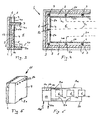
- Figure 1 shows a schematic section through the wall of a House, which has an outer wall 1, an isolation 2, several Spacer 3 and a tempering 4 with inner surface 4a includes.
- Temperier imagery 4 below is always the understood entire body, said body to the interior 6th as surface forms a wall 4a.
- the spacers 3 which with the outer wall 1 and the tempering 4, for example, fixed are connected, a defined cavity 8 formed by which tempered air is passed to the tempering 4 either to warm or cool, and thereby the Temperature of an interior 6 to influence.
- the isolation 2 consists, for example, of foam glass which is vapor-tight is, so that the cavity 8 is protected from the ingress of moisture is.
- the width of the cavity 8 and the distance between Temperier Design 4 and 2 insulation for example between 0.5 and 10 cm.
- FIG. 2 shows schematically the wall of a house, which in turn an outer wall 1, an insulation 2 and a plurality of stacked building blocks 12b includes.
- the composite of Building blocks 12b forms the tempering 4, which against the Interior 6 towards the wall 4a forms.
- a cavity 8 is formed, wherein the insulation 2 has projecting portions which the Set width of the cavity 8.
- the tempering surface 4 has below two inlet openings 8a, and also has two Outlet openings 8b.
- the fluid, the tempered air is over In the bottom 7 arranged supply lines 9a the inlet openings 8a fed, moves within the cavity 8 upwards, and flows through the outlet openings 8b back into the interior.
- the tempered air As it flows through, the tempered air is heated or cooled in particular the tempering 4, so that the interior 6 on the Temperature of the temperature control surface is heated or cooled.
- the tempered air flows through the outlet openings 8b also in the Interior 6, so that this over the incoming air again is heated or cooled.
- FIG. 3 shows in a longitudinal section two floors of a house, with projectile surfaces 7, a supporting outer wall 1 and a External insulation 2.
- the insulation 2 consists for example of Polyurethane and is chosen so thick that the dew point located within the isolation 2.
- Inside the house is one Wall 4a so spaced apart from the outer wall 1 arranged that between the outer wall 1 and the tempering 4 forming wall 4 forms a cavity 8.
- the cavity 8 has below an inlet opening 8a, which via a line 9a tempered air can be supplied, and which as air flow L, advantageously via a flow resistance means 13, to Outlet opening 8b flows.
- the tempering 4 also has two Outlet openings 8b, which a fluid-conducting connection form between the cavity 8 and the interior 6.
- the administration 9 and the inlet opening 8a could also be arranged on the ceiling be, and the outlet openings 8b be arranged in the interior 6, so that the air L flows in the cavity 8 from top to bottom.
- FIG. 4 is a plan view schematically showing an interior of the in. FIG Figure 3 shown house.
- the supporting outer wall 1 is outside surrounded by an external insulation 2.
- spacer holding elements 3 are arranged, which set the width of each cavity 8.
- the spacer elements 3 are designed in such a way and arranged that each of the three illustrated cavities 8 for is airtight or substantially air-tight, so that each cavity 8 forms an airtight container, of course with Exception of the inlet and outlet openings 8a, 8b.
- These Air-tightness is achieved, for example, through the use of Rubber, cork or even a plastic achieved.
- Each cavity 8 is air via a separate supply line 9a provided.
- the wall 4a as Temperier Chemistry 4 configured.
- the wall 4a could of course also the bottom 4b and / or the ceiling 4c a Temperature control surface 4 with a cavity 8 arranged behind it have to with the aid of air to these temperature control surfaces 4 tempering, and the air, analogous to the wall 4a, over a Outlet opening 8 b in the interior 6 to conduct.
- Figure 6 shows schematically the supply of several rooms 6 a House with tempered air.
- the rooms to be tempered are via a supply line 9a and a discharge 9b with a device 10 connected to the temperature of air.
- the device 10 can be configured as a heating and / or cooling device to the Rooms 6 heated, cooled or non-temperature-modified air supply.
- the device 10 comprises a regulating device 10a, Sensors 10b and actuators 10c, for example controllable valves.
- a temperature sensor 10b and ev. a humidity sensor arranged so that at least the Temperature of each room 6 is individually adjustable by the Air supply is controlled accordingly.
- the device 10 is preferably part of a closed air circuit, and comprises also an air inlet 10d to suck in outside air, as well as a Air outlet 10e to release used air to the environment.
- the Device preferably also includes a heat or Refrigerant to the air discharged through the air outlet 10e To remove heat or cold.
- the device 10 is For example, operated in such a way that the air in the space 6 between 2 and circulated 10 times per hour, preferably about 4.5 times.
- the temperature and the air exchange or the Air circulation can be specified independently.
- the inventive Arrangement ensures excellent hygiene, prevents that volatile organic substances such as formaldehyde or radon, respirable dusts, fungi or bacterial spores in the Room 6 accumulates, we therefore ensure a healthy Living climate, which is particularly suitable for allergy sufferers.
- a small Air flow speed can reach on the one hand the air with a correspondingly adapted speed to the cavity 8 can be fed, and also the outlet openings 8b be designed accordingly.
- the outlet openings 8 b can be free selectable places, in freely selectable number and with freely selectable Geometry in the interior 6 open.
- FIG. 5 shows schematically a prefabricated component 11 with a Box-shaped hollow body with tempering surface 4, wherein the Inlet opening 8a and the outlet openings 8b and a are connected within the hollow body cavity, wherein the cavity may have any possible geometry.
- This Prefabricated element 11 may also be provided with an insulation 2 be.
- FIGS. 7a to 7e show differently designed refurbishment units 12b, which are particularly suitable for refurbishing existing buildings in order to form a cavity 8 with inlet openings 8a and outlet openings 8b in existing interior spaces 6, which have temperature control via supply and discharge lines 9a, 9b Air are available.
- FIG. 7a shows a refurbishment module 12b with a temperature control surface 4 and an insulation material 2, in which fluid-conducting recesses 12c are inserted, through which the tempered air flows.
- FIGS. 8a and 8b show exemplary embodiments of the profile of the recesses 12c, as they could run in the refurbishment modules according to FIGS. 7a, 7b and 7c.
- the refurbishment module 7b has outlet openings 8b, which form a fluid-conducting connection with the recesses 12c.
- the recesses 12c are arranged in the stone forming the temperature surface 4.
- the insulation 2 is designed to be narrow and strip-shaped, so that broad, vertically extending recesses are formed.
- the refurbishment units 12 are preferably stacked in a staggered manner to form a composite, with the cavity, with the exception of the inlet and outlet openings 8a, 8b, preferably being made air-tight towards the interior 6.
- the heat surface 4 forming part of the redevelopment block 12b is preferably made of a material of the group stone, concrete, aerated concrete, expanded clay, wood, cardboard, plaster, ceramics or plastic.
- the refurbishment module 12b is preferably made very thin, and overall has a thickness D of, for example, 1 to 6 cm, and preferably a thickness D of about 2 cm. In this case, the tempering surface 4 can also be made very thin, and have a thickness D1 between 0.5 to 2 cm.
- the refurbishment module 12b has, for example, a surface 4a of 60 ⁇ 45 cm.
- flow resistance means 13 may arrange the flow rate of the air within the To reduce cavity 8, and / or the heat output of the flowing air to the temperature control surface 4 to increase.
- Flow resistance means 13 may be used in a variety of ways Be designed execution means, and for example, a Have surface structure similar to an egg carton.
Landscapes
- Engineering & Computer Science (AREA)
- Architecture (AREA)
- Physics & Mathematics (AREA)
- Civil Engineering (AREA)
- General Engineering & Computer Science (AREA)
- Mechanical Engineering (AREA)
- Combustion & Propulsion (AREA)
- Electromagnetism (AREA)
- Chemical & Material Sciences (AREA)
- Structural Engineering (AREA)
- Acoustics & Sound (AREA)
- Life Sciences & Earth Sciences (AREA)
- Sustainable Development (AREA)
- Building Environments (AREA)
Abstract
Description
Die erfindungsgemässe Anordnung ist jedoch auch zur Sanierung bestehender Häuser geeignet, indem an den bestehenden Aussenwänden die Temperierflächen mit Hohlräumen angebracht werden. Zur Sanierung bestehender Häuser sind insbesondere speziell angepasste Sanierungsmittel wie Sanierungsbausteine geeignet, welche in einem Verbund angeordnet die erfindungsgemässe Anordnung ausbilden.
- Figur 1
- eine schematische Detailansicht eines Fluid leitenden Hohlraumes;
- Figur 2
- schematisch eine erfindungsgemässe Anordnung mit Fluid leitendem Hohlraum sowie Eintritts- und Austrittsöffnungen;
- Figur 3
- ein Längsschnitt durch die Aussenwand eines Hauses mit tragender Struktur und Aussenisolation, Innenwand und dazwischen angeordnetem Fluid leitendem Hohlraum;
- Figur 4
- schematisch eine Draufsicht auf einen Innenraum, umgeben von einer tragenden Struktur mit Aussenisolation, Innenwand und dazwischen angeordneten Fluid leitenden Hohlräumen;
- Figur 5
- eine schematische Ansicht eines Fertigelementes mit Aussenisolation und Fluid leitendem Hohlraum mit Eintritts- und Austrittsöffnung;
- Figur 6
- schematisch eine Vorrichtung zur Temperierung von Luft, welche über Luftzuführkanäle mit drei separaten Innenräumen verbunden ist.
- Figuren 7a-7e
- verschieden ausgestaltete Sanierungsbausteine mit Fluid leitenden Hohlräumen;
- Figur 8a, 8b
- beispielhafte Verläufe von Hohlräumen im Sanierungsbaustein.
- Die Hohlräume 8 sind sehr kostengünstig herstellbar. Insbesondere bei einem Neubau ist eine im wesentlichen luftdichte Aussenhülle sowie die Erstellung der Hohlräume einfach und kostengünstig möglich.
- Die Temperierflächen 4, welche als Wände 4a, Böden 4b oder Decke 4c ausgestaltet sind, werden erwärmt (oder gekühlt). Die erwärmte Temperierfläche 4 hat ein sehr angenehmes Raumklima zur Folge, da der Innenraum 6 kaum kalte (oder warme) Begrenzungsflächen aufweist.
- Die einzelnen Hohlräume 8 könnten getrennt mit Luft beschickt werden, sodass die Temperatur der jedem Hohlraum zugeführt Luft individuell eingestellt werden kann. Zudem kann für jeden Raum 6 eine individuelle Raumtemperatur und/oder eine individuelle Luftaustauschrate vorgegeben werden.
- Da die Hohlräume 8 über die Eintrittsöffnung 8a in den Innenraum 6 münden finden ständig eine Umwälzung der Luft im Innenraum 6 statt, was insbesondere bei hochdicht ausgestalteten Häusern von zentraler Bedeutung ist.
- Die Strömungsgeschwindigkeit der über die Zuleitung 9a zugeführten Luft ist vorzugsweise einstellbar, wobei zudem durch eine geschickte Anordnung, Ausgestaltung und Anzahl der Austrittsöffnungen 8b die Strömungsgeschwindigkeit im Innenraum 6 derart beeinflusst werden kann, dass diese nicht als unangenehm empfunden wird und kaum oder nicht spürbar ist.
- Aufgrund der Zuführung der Luft vom Hohlraum 8 in den Innenraum 6 ist ein genügend hoher Luftwechsel sowie eine schnelle Temperierung des Raumes möglich, wobei die Wärme oder Kälte zudem in der Temperierfläche 4 bespeichert wird, und dadurch langfristig wirken kann.
- Die Belüftung des Hohlraumes 8 gewährleitstet dass sich darin kein Kondenswasser bildet, oder dass dieses wegen der durch den Hohlraum 8 strömenden Luft nur kurzfristig vorhanden ist. Ein Feuchteschaden im Bereich von Aussenwand 1, Isolation 2 und Hohlraum 8 ist somit ausgeschossen.
- Die Anordnung kann äusserst kostengünstig gebaut werden, da die Hohlräume 8 sehr günstig herstellbar sind, und da als Zuleitung 9a beispielsweise kostengünstige Kunststoffrohre verwendbar sind, sodass, beispielsweise im Vergleich zu einer Bodenheizung, die Installationskosten der Zuleitungen 9a äusserst günstige sind.
- Die Anordnung ist hervorragend geeignet zur Sanierung bestehender Gebäude, weil es einerseits sehr einfach und kostengünstig ist, die bestehenden Wände eines Innenraumes 6 mit einer Temperierfläche 4 zu versehen, hinter welcher ein Hohlraum 8 ausgebildet ist. Zudem sind die Zuleitungen 9a sehr kostengünstig zu verlegen. Ein zusätzlicher, wichtiger Vorteil ist darin zu sehen, dass diese Anordnung gewährleistet, dass sich im Innenraum 8 kein Kondenswasser ansammelt.
- Die Anordnung ermöglicht zudem Neubauten sehr kostengünstig zu erstellen. Werden beispielsweise die Distanzhalter 3 zugleich als Träger ausgestaltet, so kann die Aussenwand 1 sehr dünn ausgestaltet sein, da diese nun noch eine bezüglich dem Hohlraum 8 dichtenden Funktion gewährleisten muss, jedoch keine Stützfunktion übernehmen muss.
- Dieselbe Anordnung ist für jegliche Art von Häusern geeignet, beispielweise für Wohnhäuser, Lagerhäuser, Einkaufszentren, oder Bürogebäude. Die Anordnung ist zudem für Bauten in jeder Klimazonen geeignet. Im kühlen Norden ist üblicherweise nur eine Beheizung der Hohlräume im Winter erforderlich. In gemässigten Zonen ist im Winter eine Beheizung erforderlich und im Sommer eine Kühlung erwünscht. Zudem kann es erwünscht sein in der Übergangszeit die Innenräume mit nicht temperierter Aussenluft zu versorgen. In südlichen, heissen Zonen ist nur eine Kühlung erforderlich.
- Die Anordnung wird vorteilhafterweise mit einer zentrale Luftaufbereitung betrieben, sodass die Innenluft des gesamten Hauses nicht nur temperierbar ist, sondern auch kostengünstig noch weiter behandelt werden kann, indem die Luft beispielsweise entfeuchtet oder befeuchtet, von Partikeln oder Gerüchen gereinigt, oder mit Zusatzstoffen wie Ionen oder Düften versehen wird. Die Temperierung der Luft könnte jedoch auch durch eine innerhalb des Hohlraumes 8 angeordneten Vorrichtung erfolgen.
- Die Anordnung ermöglicht über die zentrale Luftaufbereitung eine Wärme- oder Kälterückgewinnung aus der verbrauchten Luft. Eine Klimaanlage kann einfach verwendet werden.
Der Sanierungsbaustein 12b ist vorzugsweise sehr dünn ausgestaltet, und weist insgesamt eine Dicke D von beispielsweise 1 bis 6 cm auf, und vorzugsweise eine Dicke D von etwas 2 cm. Dabei kann die Temperierfläche 4 auch sehr dünn ausgestaltet sein, und eine Dicke D1 zwischen 0.5 bis 2 cm aufweisen. Der Sanierungsbaustein 12b weist beispielsweise eine Oberfläche 4a von 60 x 45 cm auf.
Claims (24)
- Anordnung zur Temperierung sowie Be- und Entlüftung von Innenräumen (6) eines Hauses (5) mittels temperierter Luft, wobei die Innenräume eine als Wand (4a) und/oder Boden (4b) und/oder Decke (4c) ausgestaltete Temperierfläche (4) aufweisen, hinter welcher ein Fluid leitender Hohlraum (8) ausgebildet ist, wobei der Fluid leitende Hohlraum (8) zumindest eine Eintrittsöffnung (8a) sowie zumindest eine Austrittsöffnung (8b) für die temperierte Luft aufweist und ansonst abgedichtet ausgestaltet ist, um die durch die Eintrittsöffnung (8a), den Fluid leitenden Hohlraum und die Austrittsöffnung (8b) strömende temperierte Luft derart zu leiten, dass die Temperatur der Temperierfläche (4) beeinflusst wird, und wobei die Austrittsöffnung (8b) in den Innenraum (6) mündet.
- Anordnung gemäss Anspruch 1, dadurch gekennzeichnet, dass der Fluid leitende Hohlraum (8), mit Ausnahme der Eintritts- und Austrittsöffnung (8a, 8b), luftdicht ausgestaltet ist.
- Anordnung nach einem der vorhergehenden Ansprüche, dadurch gekennzeichnet, dass die Austrittsöffnung (8b) innerhalb der Temperierfläche (4) angeordnet ist.
- Anordnung nach einem der vorhergehenden Ansprüche, dadurch gekennzeichnet, dass der Innenraum (6) eine Mehrzahl von gegenseitig abgedichteten, Fluid leitenden Hohlräumen (8) mit Eintrittsöffnungen (8a) und Austrittöffnungen (8b) aufweist.
- Anordnung nach einem der vorhergehenden Ansprüche, dadurch gekennzeichnet, dass Zuführ- und Steuermittel (9,10) derart angeordnet sind, dass jeder Fluid leitende Hohlraum (8) separat ansteuerbar mit temperierter und/oder befeuchteter Luft versorgbar ist.
- Anordnung nach einem der vorhergehenden Ansprüche, dadurch gekennzeichnet, dass die Anordnung als Fertigbauelement (11) ausgestaltet ist.
- Anordnung nach einem der Ansprüche 1 bis 5, dadurch gekennzeichnet, dass das Haus eine Innen- und eine Aussenwand (1,4) aufweist und ein Dichtungsmittel (3) derart angeordnet ist, dass zwischen der Innen- und Aussenwand (1,4) eine Mehrzahl abgedichteter, Fluid leitender Hohlräume (8) ausgebildet sind.
- Anordnung nach einem der Ansprüche 1 bis 5, dadurch gekennzeichnet, dass der Fluid leitende, abgedichtete Hohlraum (8) durch Sanierungsmittel (12), insbesondere eine Sanierungswand (12a) oder eine Mehrzahl von Sanierungsbausteinen (12b) bebildet ist, welche vor einer bestehenden Wand (1) angeordnet sind, und welche derart ausgestaltet sind, dass sie sowohl einen Fluid leitenden Hohlraum (8) als auch eine Temperierfläche (4) ausbilden.
- Verfahren zur Temperierung sowie Be- und Entlüftung von Innenräumen (6) eines Hauses mittels temperierter Luft indem die Luft erwärmt und/oder gekühlt wird, indem diese temperierte Luft einem abgedichteten Hohlraum (8) zugeführt und im Hohlraum (8) über eine Temperierfläche (4) geleitet wird, welche eine Wand (4a) und/oder Boden (4b) und/oder Decke (4c) des Innenraumes (6) bildet, und indem die gesamte temperierte Luft danach in den Innenraum geleitet wird.
- Verfahren nach Anspruch 9, dadurch gekennzeichnet, dass die Temperatur und/oder die Fliessgeschwindigkeit und/oder die Luftmenge der den Hohlräumen (8) zugeführten Luft zumindest für einige Hohlräume (8) individuell vorgebbar ist.
- Verfahren nach Anspruch 9 oder 10, dadurch gekennzeichnet, dass das Haus und/oder jeder Innenraum (6) eine Mehrzahl von Temperierflächen (4) mit zugeordneten, abgedichteten Fluid leitenden Hohlräumen (8) aufweist, und dass die Temperatur und/oder die Fliessgeschwindigkeit und/oder die Luftmenge der jedem Fluid leitenden Hohlraum (8) zugeführten Luft individuell vorgebbar ist.
- Haus umfassend eine Mehrzahl von Anordnungen gemäss einem der Ansprüche 1 bis 8, umfassend eine Vorrichtung (10) zur Temperierung von Luft sowie umfassend Luftzuführkanäle (9a), welche eine Fluid leitende Verbindung zwischen der Vorrichtung (10) zur Temperierung sowie den Eintrittsöffnungen (8a) der Fluid leitenden Hohlräume (8) bilden, sowie umfassend eine Regelvorrichtung (10a), Sensoren (10b) und Aktuoren (10c), um die Temperatur und/oder die Fliessgeschwindigkeit und/oder die Luftmenge und/oder die Luftfeuchtigkeit der den Fluid leitenden Hohlräumen (8) zugeführten temperierten Luft insbesondere individuell zu beeinflussen.
- Sanierungsmittel (12) zur nachträglichen Erstellung einer Anordnung gemäss einem der Ansprüche 1 bis 5 oder 8, umfassend eine Temperierfläche (4) bestehend aus einem Material der Gruppe Stein, Beton, Porenbeton, Blähton, Holz, Karton, Gips, Keramik, Kunststoff, sowie umfassend Ausnehmungen (12c), welche derart angeordnet und ausgestaltet sind, dass das Sanierungsmittel (12), insbesondere im Verbund angeordnet, einen Fluid leitenden Hohlraum (8) mit Eintritts- und Austrittsöffnung (8a, 8b) ausbildet, wobei der Hohlraum (8) entweder vom Sanierungsmittel (12) an sich, oder vom Sanierungsmittel (12) in Kombination mit einer Wand ausgebildet ist.
- Sanierungsmittel (12) nach Anspruch 13, dadurch gekennzeichnet, dass dieses auf der Rückseite des die Temperierfläche (4) ausbildenden Materials angeordnete Abstandhaltemittel (3) aufweist, welche über die Rückseite vorstehen.
- Sanierungsmittel (12) nach Anspruch 13, dadurch gekennzeichnet, dass dieses auf der Rückseite des die Temperierfläche (4) ausbildenden Materials eine Schicht aus Isolationsmaterial (2) aufweist.
- Sanierungsmittel (12) nach Anspruch 15, dadurch gekennzeichnet, dass dieser Fluid leitende Ausnehmungen (12c) oder Kanäle (12c) aufweist, welche derart angeordnet und ausgestaltet sind, dass diese bei in einem Verbund angeordneten Sanierungsmitteln (12) einen gemeinsamen, Fluid leitenden Hohlraum (8) ausbilden.
- Sanierungsmittel (12) nach einem der Ansprüche 13 bis 16, dadurch gekennzeichnet, dass dieses Fluid leitenden Ausnehmungen (12c) oder Kanäle (12c) in einer Schicht aus wasserdampfdiffusionsdichtem Material (2) ausgebildet sind.
- Sanierungsmittel (12) nach einem der Ansprüche 13 bis 17, dadurch gekennzeichnet, dass dieses als ein Sanierungsbaustein (12b) ausgestaltet ist.
- Herstellung von Kanälen und Luftebenen zwischen mindestens einem Schaumglasrohling (2) als tauwasserfreie Fixierschicht, und mindestens einer auf Abstand gebrachten Beplankung (4), wobei die Beplankung aus unterschiedlichen Materialien gefertigt sein kann, jedoch vorzugsweise aus geologisch monolithischen Rohstoffen besteht, und wobei die Längen und Breiten der Kanäle und Luftebenen frei wählbar sind, und durch Distanz- und Fixierlager entstehen.
- Herstellung von Distanz- und Fixierlager zur Größenbestimmung von Kanälen und Luftebenen und zur Abstandsbestimmung zwischen dem Schaumglasrohling (2) und der Beplankung (4), wobei die Abmessungen und die Form der Distanz- und Fixierlager (3) frei wählbar und variabel sind, und wobei die Form rechteckig, quadratisch, rund oder elliptisch sein kann oder auch andere Geometrien aufweist, wobei die Maße und Formen sich nach Qualität und Menge des benötigten Luftvolumens und der Zusammensetzung der benötigten Atmosphäre richten, und wobei die Distanz- und Fixierlagen vorzugsweise aus armiertem Schaumglas bestehen, wobei der Baudämmstein aus mindestens einem Schaumglasrohling (2) und mindestens einer Beplankung (1) bestehen kann, oder mehreren Beplankungen (1,4), die vorzugsweise aus Porenbeton bestehen, wobei die Schichtenfolge grundsätzlich Porenbeton (1) mit Schaumglas (2) in fester Verbindung ist und die Befestigung einer weiteren Beplankung auf Abstand (4), mittels der genannten Distanz- und Fixierlager erfolgt.
- Herstellung eines Elementes nach Patentanspruch 20, jedoch in der Schichtenfolge, Beplankung (1) mit Schaumglas (2) als tauwasserfreie Fixierschicht und Beplankung (4), jedoch ohne Distanz- und Fixierlager (3), aber untereinander in fester Verbindung, wobei das Schaumglas (2) immer im mittleren Bereich zwischen den beiden äußeren Beplankungen fest eingebunden ist.
- Herstellung eines Elementes in der Schichtenfolge, Beplankung (1) vorzugsweise aus Porenbeton, mit einer tauwasserfreien Fixierschicht (2) vorzugsweise bestehend aus Schaumglas, wobei beide Schichten fest miteinander verbunden sind.
- Herstellung eines Elementes unter Verwendung der Beplankung (4), vorzugsweise aus Porenbeton, und der tauwasserfreien Fixierschicht (2), vorzugsweise aus Schaumglas, wobei die Beplankung (4) und die Fixierschicht (2) durch die Distanz- und Fixierlager (3) auf frei wählbaren Abstand gehalten werden, wobei die Distanz- und Fixierlager vorzugsweise aus armiertem Schaumglas oder aus der Gruppe Stein, Beton, Porenbeton, Blähton, Holz, Karton, Gips, Kunststoff, sowie umfassend Ausnehmungen bestehen.
- Herstellung eines Elementes unter Verwendung von mindestens zwei geologisch monolithischer Beplankungen (1,4), vorzugsweise aus Porenbeton, die durch Distanz- und Fixierlager (3) auf Abstand fixiert werden, die vorzugsweise aus armiertem Schaumglas bestehen.
Priority Applications (1)
| Application Number | Priority Date | Filing Date | Title |
|---|---|---|---|
| EP04405136A EP1529890A3 (de) | 2003-11-09 | 2004-03-09 | Anordnung und Verfahren zur Temperierung sowie Be-und Entlüftung von Innenräumen |
Applications Claiming Priority (5)
| Application Number | Priority Date | Filing Date | Title |
|---|---|---|---|
| WOPCT/EP03/12470 | 2003-11-09 | ||
| EP0312470 | 2003-11-09 | ||
| WOPCT/CH20/04000043 | 2004-01-27 | ||
| CH2004000043 | 2004-01-27 | ||
| EP04405136A EP1529890A3 (de) | 2003-11-09 | 2004-03-09 | Anordnung und Verfahren zur Temperierung sowie Be-und Entlüftung von Innenräumen |
Publications (2)
| Publication Number | Publication Date |
|---|---|
| EP1529890A2 true EP1529890A2 (de) | 2005-05-11 |
| EP1529890A3 EP1529890A3 (de) | 2005-06-08 |
Family
ID=34436503
Family Applications (1)
| Application Number | Title | Priority Date | Filing Date |
|---|---|---|---|
| EP04405136A Withdrawn EP1529890A3 (de) | 2003-11-09 | 2004-03-09 | Anordnung und Verfahren zur Temperierung sowie Be-und Entlüftung von Innenräumen |
Country Status (1)
| Country | Link |
|---|---|
| EP (1) | EP1529890A3 (de) |
Cited By (6)
| Publication number | Priority date | Publication date | Assignee | Title |
|---|---|---|---|---|
| NL2005053C2 (nl) * | 2010-07-08 | 2012-01-10 | Snel Bouw Muren N V | Spouwmuur, alsmede bouwelement en werkwijze. |
| DE202015106184U1 (de) | 2014-11-14 | 2016-03-11 | Saint-Gobain Isover A/S | System für nachgerüstete Isolierung |
| FR3028598A1 (fr) * | 2014-11-18 | 2016-05-20 | Edouard Serras | Batiment basse consommation ou a energie positive et procede de regulation de la temperature et de l'humidite relative dans ce batiment |
| CN108661265A (zh) * | 2018-05-25 | 2018-10-16 | 中国科学院广州能源研究所 | 一种可调温的复合陶瓷板 |
| EP4450724A1 (de) * | 2023-04-20 | 2024-10-23 | IVL Immobilienvermittlung Landau GmbH | System zum wärmedämmen und temperieren eines raumes und/oder daches eines gebäudes |
| DE102025105691A1 (de) * | 2025-02-14 | 2026-08-20 | Max Bögl Stiftung & Co. Kg | Betonbauteil, Bauwerk, System sowie Verwendung |
Family Cites Families (3)
| Publication number | Priority date | Publication date | Assignee | Title |
|---|---|---|---|---|
| NL55714C (de) * | 1900-01-01 | |||
| FR2522121A1 (fr) * | 1982-02-23 | 1983-08-26 | Quille Entreprise | Dispositif et element pour ameliorer les conditions de ventilation d'un local |
| DE3609452A1 (de) * | 1985-03-04 | 1987-01-29 | Georg Thesz | Aussenwandkonstruktion an einem bauwerk |
-
2004
- 2004-03-09 EP EP04405136A patent/EP1529890A3/de not_active Withdrawn
Cited By (8)
| Publication number | Priority date | Publication date | Assignee | Title |
|---|---|---|---|---|
| NL2005053C2 (nl) * | 2010-07-08 | 2012-01-10 | Snel Bouw Muren N V | Spouwmuur, alsmede bouwelement en werkwijze. |
| DE202015106184U1 (de) | 2014-11-14 | 2016-03-11 | Saint-Gobain Isover A/S | System für nachgerüstete Isolierung |
| FR3028598A1 (fr) * | 2014-11-18 | 2016-05-20 | Edouard Serras | Batiment basse consommation ou a energie positive et procede de regulation de la temperature et de l'humidite relative dans ce batiment |
| WO2016079424A1 (fr) * | 2014-11-18 | 2016-05-26 | Edouard Serras | Bâtiment basse consommation ou à énergie positive et procédé de régulation de la température et de l'humidité relative dans ce bâtiment |
| CN108661265A (zh) * | 2018-05-25 | 2018-10-16 | 中国科学院广州能源研究所 | 一种可调温的复合陶瓷板 |
| CN108661265B (zh) * | 2018-05-25 | 2023-11-10 | 中国科学院广州能源研究所 | 一种可调温的复合陶瓷板 |
| EP4450724A1 (de) * | 2023-04-20 | 2024-10-23 | IVL Immobilienvermittlung Landau GmbH | System zum wärmedämmen und temperieren eines raumes und/oder daches eines gebäudes |
| DE102025105691A1 (de) * | 2025-02-14 | 2026-08-20 | Max Bögl Stiftung & Co. Kg | Betonbauteil, Bauwerk, System sowie Verwendung |
Also Published As
| Publication number | Publication date |
|---|---|
| EP1529890A3 (de) | 2005-06-08 |
Similar Documents
| Publication | Publication Date | Title |
|---|---|---|
| EP1062463B1 (de) | Klimatisierungsverfahren von gebäuden sowie klimatisiertes gebäude | |
| DE19809974B4 (de) | Gebäude mit Klimatisierung | |
| EP0097361A1 (de) | Wandelemente für Fertighäuser | |
| EP2142858A1 (de) | Plattenförmiges verkleidungselement für eine mauer und mauerverkleidung | |
| DE3720554A1 (de) | Plattenfoermiges bauelement | |
| DE19845557C2 (de) | Lüftungsdämmsystem | |
| EP2791436B1 (de) | Gebäude mit einem in eine betondecke des gebäudes integrierten raumkonditionierungssystem zum kühlen, heizen und zur belüftung | |
| DE3441597A1 (de) | Bio-klima-therm-wandflaechenheizungs- und lueftungselement | |
| DE29722890U1 (de) | Massive Fertigteilwand mit Klimakomponenten | |
| DE3507594C2 (de) | ||
| DE19757951A1 (de) | Massive Fertigteilwand mit Klimakomponenten | |
| DE102010056047B3 (de) | Wandelement sowie Klimatisierungssystem und Verfahren zum Klimatisieren von Bauwerken | |
| DE3609452A1 (de) | Aussenwandkonstruktion an einem bauwerk | |
| DE202011101199U1 (de) | Stallgebäude mit Wärmerückgewinnung | |
| DE19639128A1 (de) | Lüftungswärmetauscher | |
| EP4483101B1 (de) | Temperieranordnung, verfahren zu dessen installation und verfahren zum temperieren eines raumes | |
| EP2557369A2 (de) | Vorrichtung zum Klimatisieren eines Innenraums und zugehöriges Verfahren | |
| DE29519093U1 (de) | Vorrichtung zum Gewinnen von Frischluft für die Luftkonditionierung | |
| DE102010002198A1 (de) | Lüftungssystem für Gebäude-Deckenelemente | |
| EP0147827B1 (de) | Verfahren und Bauelemente zur Klimatisierung von Arbeits-, Wohn- und Aufenthaltsräumen | |
| DE102022113036A1 (de) | Lüftungssystem zur Austrocknung von durchfeuchteten Bauteilen, sowie Verfahren zur Trocknung eines durchfeuchteten Bauteils mittels des Lüftungssystems | |
| DE10223896A1 (de) | Verfahren und Einrichtung zur Vermeidung von Feuchteschäden und Schimmelpilzbildung | |
| CH565916A5 (en) | Prefabricated double-skinned insulated reinforced-concrete wall element. - with connecting cross arms in rows attached to inner and outer shells | |
| DE19648303A1 (de) | Rohr-Wandheizung aus Metallrohren und Verfahren zur Herstellung | |
| DE202011103761U1 (de) | Raumdeckensystem |
Legal Events
| Date | Code | Title | Description |
|---|---|---|---|
| PUAI | Public reference made under article 153(3) epc to a published international application that has entered the european phase |
Free format text: ORIGINAL CODE: 0009012 |
|
| PUAL | Search report despatched |
Free format text: ORIGINAL CODE: 0009013 |
|
| AK | Designated contracting states |
Kind code of ref document: A2 Designated state(s): AT BE BG CH CY CZ DE DK EE ES FI FR GB GR HU IE IT LI LU MC NL PL PT RO SE SI SK TR |
|
| AX | Request for extension of the european patent |
Extension state: AL HR LT LV MK |
|
| AK | Designated contracting states |
Kind code of ref document: A3 Designated state(s): AT BE BG CH CY CZ DE DK EE ES FI FR GB GR HU IE IT LI LU MC NL PL PT RO SE SI SK TR |
|
| AX | Request for extension of the european patent |
Extension state: AL HR LT LV MK |
|
| AKX | Designation fees paid | ||
| REG | Reference to a national code |
Ref country code: DE Ref legal event code: 8566 |
|
| STAA | Information on the status of an ep patent application or granted ep patent |
Free format text: STATUS: THE APPLICATION IS DEEMED TO BE WITHDRAWN |
|
| 18D | Application deemed to be withdrawn |
Effective date: 20051209 |