EP1529716A1 - Fahrzeug-Hilfskraftlenkung mit Elektromotor - Google Patents
Fahrzeug-Hilfskraftlenkung mit Elektromotor Download PDFInfo
- Publication number
- EP1529716A1 EP1529716A1 EP04023467A EP04023467A EP1529716A1 EP 1529716 A1 EP1529716 A1 EP 1529716A1 EP 04023467 A EP04023467 A EP 04023467A EP 04023467 A EP04023467 A EP 04023467A EP 1529716 A1 EP1529716 A1 EP 1529716A1
- Authority
- EP
- European Patent Office
- Prior art keywords
- rotor
- state
- electric motor
- control
- speed
- Prior art date
- Legal status (The legal status is an assumption and is not a legal conclusion. Google has not performed a legal analysis and makes no representation as to the accuracy of the status listed.)
- Granted
Links
Images



Classifications
-
- B—PERFORMING OPERATIONS; TRANSPORTING
- B62—LAND VEHICLES FOR TRAVELLING OTHERWISE THAN ON RAILS
- B62D—MOTOR VEHICLES; TRAILERS
- B62D5/00—Power-assisted or power-driven steering
- B62D5/04—Power-assisted or power-driven steering electrical, e.g. using an electric servo-motor connected to, or forming part of, the steering gear
- B62D5/0457—Power-assisted or power-driven steering electrical, e.g. using an electric servo-motor connected to, or forming part of, the steering gear characterised by control features of the drive means as such
- B62D5/046—Controlling the motor
-
- B—PERFORMING OPERATIONS; TRANSPORTING
- B62—LAND VEHICLES FOR TRAVELLING OTHERWISE THAN ON RAILS
- B62D—MOTOR VEHICLES; TRAILERS
- B62D5/00—Power-assisted or power-driven steering
- B62D5/04—Power-assisted or power-driven steering electrical, e.g. using an electric servo-motor connected to, or forming part of, the steering gear
- B62D5/0457—Power-assisted or power-driven steering electrical, e.g. using an electric servo-motor connected to, or forming part of, the steering gear characterised by control features of the drive means as such
- B62D5/046—Controlling the motor
- B62D5/0472—Controlling the motor for damping vibrations
Definitions
- the invention relates to a vehicle power steering system with electric motor after the The preamble of claim 1 and a method for controlling an electric motor such a vehicle power steering system according to the preamble of the sibling Claim.
- Vehicle power steering with electric motor are often also short Electric power steering systems are and are especially in vehicles of the lower class (Small car) spread. Increasingly, however, they are also used in vehicles used the middle and upper class.
- These vehicle power steering systems have usually an electronic control that controls the electric motor dynamically, so that this in addition to the applied by the driver of the vehicle Steering torque generates a steering force supporting engine torque.
- the Electric steering systems have opposite the hydraulic power steering systems, too briefly referred to as hydraulic steering or power steering, the advantage that the electric motor can be controlled very accurately by means of a control.
- the known arrangements are usually processor-controlled circuits, the are programmable, so that the control of the electric motor the respective Adapted requirements and the behavior of the electric steering very flexible can be adjusted.
- the transmission of the generated by the electric motor Power steering engine torque on the steering mechanism usually takes place via a geared Compound, preferably via a worm gear.
- a geared Compound preferably via a worm gear.
- the object of the invention is to provide a vehicle power steering with electric motor and to propose a method for controlling the electric motor, in which the mentioned disadvantages do not occur.
- control regulate the rotor speed of the rotor of the rotor Electric motor evaluates and increases the dynamic inertia of the rotor, if the Evaluation of the rotor speed indicates an unstable state of the scheme.
- the electric motor is an asynchronous motor and when the control in the unstable state by means of the dynamic inertia of the rotor a field-oriented control of the induction motor increases.
- control monitors the vehicle speed and evaluates the rotor speed only to detect the unstable condition if the driving speed does not exceed a first predefinable value. This ensures that a chatter detection only at very low Driving speeds is performed.
- the control monitors the vehicle speed and in the unstable state of the control, the dynamic inertia of the rotor only then increases when the vehicle speed is a second predetermined value does not exceed. This ensures that only at low speeds the dynamic behavior of the steering is somewhat limited, at higher Speeds are not.
- a Characteristic curve function that is at least determined by the vehicle speed, in particular the vehicle speed, the rotor speed and a Sign change of the steering torque
- control is a PD controller, the at least one proportional element and at least one differential element, wherein the PD controller is the electric motor controlled by a predetermined by its proportional element characteristic function and in the unstable state, the characteristic function with a zeitverzögemden Applied filter function.
- PD controller is the electric motor controlled by a predetermined by its proportional element characteristic function and in the unstable state, the characteristic function with a zeitverzögemden Applied filter function.
- the engine control is performed on a state machine that includes three states, wherein the first state is assumed to be the recognition of the unstable one State of the scheme to activate or deactivate, the second or third state is taken to the evaluation of the rotor speed to Detecting the unstable state.
- the vehicle speed is monitored and when to detect the unstable State is changed to the second or third state, if the Vehicle speed exceeds a predetermined first value, where off the time change of the rotor speed the positive or negative Rotor acceleration is determined and compared with a gradient limit, wherein the second state is changed, if the positive rotor acceleration exceeds the gradient threshold, and where changed to the third state if the negative rotor acceleration exceeds the gradient limit.
- the vehicle speed is monitored and recognizing the unstable state is deactivated if the vehicle speed exceeds the predetermined second value.
- Negative rotor acceleration is compared with the gradient limit and It checks whether this gradient limit is less frequent than a predefinable one Number is exceeded and, if so, changed to the first state is to disable the detection of the unstable state or, if not the case is, in the third state is changed.
- the positive rotor acceleration is compared with the gradient limit value and It checks whether this gradient limit is less frequent than a predefinable one Number is exceeded and, if so, changed to the first state is to disable the detection of the unstable state or, if not the case is, in the second state is changed.
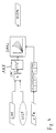
- FIG. 1 shows a control PDR according to a conventional circuit design.
- This control is designed as a PD controller and is used to control a Electric motor in a power steering system. From different input data or Signals an engine torque MSM (Motor Sollmomnent) is calculated, which is the Electric motor to support der.manuellen steering force produce.
- MSM Motor Sollmomnent
- the Input variables for the circuit shown are u.a. a support moment USM, which represents the proportional proportion of the control shown, as well as a signal DA corresponding to a first derivative component.
- TKM which ein Inertia compensation torque represents. Further input variables should be here will not be considered in detail.
- the signals USM, DA and TKM are from Input modules determined, which in the following with reference to FIG. 2 closer to be discribed.
- This setpoint MSM is a (not shown) electric motor control fed, which is preferably a field-oriented engine control.
- the Electric motor optimally controlled depending on the different operating variables become.
- Fig. 2 consisting of three parts 2a, 2b and 2c, are now the individual Input modules are shown, which are the input variables for the previously described Supply regulation.
- FIG. 2a shows an input module which contains the assistance torque USM calculated, based on the occurring steering torque LM and the current Vehicle speed vfz.
- this is preferably via a torsion bar and torque sensor detected steering torque LM with a so-called Support factor USF multiplied, which can be between 0 and 150%.
- the thus weighted steering torque is then based on a family of curves SAKL transferred to the desired support torque USM.
- the family of characteristics represents a group of function curves that express the relationship between Play support torque and steering torque. Depending on the measured vehicle speed vfz will now be one of these characteristics selected. At low speeds, the characteristic is steeper than at high speeds. Accordingly, at low speeds one higher assist torque calculated than at high speeds.
- FIG. 2b shows a circuit for calculating the first differential component DA.
- This is calculated from the input variables USM, So the previously calculated support torque, as well as two predefinable Factors, namely a first factor FZ1, which sets the filter time for a Delay member D indicates, and from a determinable D-share factor DAF, the for example, between 0 and 20 milliseconds.
- a first factor FZ1 which sets the filter time for a Delay member D indicates, and from a determinable D-share factor DAF, the for example, between 0 and 20 milliseconds.
- a comparator and in parallel one Delay D supplied, so that the current signal USM is compared with the same, but delayed, signal. Consequently, a differentiation of the Support torque USM performed.
- the delay depends on the previously selected filter time, which indicates the first factor FZ1 and which between a and eight milliseconds.
- the output of the comparator is in proportion to the filter time FZ1 set. This quotient formation results in a signal which subsequently is multiplied by the predetermined D-factor DAF. This results in finally the desired D-share DA.
- Fig. 2c shows a circuit for determining the Inertia compensation torque TKM.
- This circuit is basically the same constructed as the circuit previously described in FIG. 2b. However, be here as input variables, the rotor speed RDZ and a second factor FZ2 and a Rotor inertia factor RTF1 linked together. The rotor speed is differentiated as a function of FZ2 and then divided by this factor FZ2 then be multiplied by the factor RTF1. This then results in the desired inertia compensation torque.
- circuit shown here with reference to FIGS. 1 and 2 is not yet in the first Location, possibly occurring rat, i. disturbing effects within an unstable Condition, to compensate or possibly completely prevent. Is to however, such a circuit constructed in accordance with the invention is capable of doing so For example, in Fig. 3 is shown.
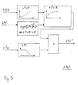
- the inventive idea is based on the knowledge that in the case of an unstable Condition, the annoying Rattem can be turned off by, in this case the dynamic inertia of the rotor is increased. This is preferably done by achieved that the inertia compensation torque (see Fig. 2c), which Usually positive (RTF1> 0), significantly reduced or even negative Sign gets.
- the amount of the usual factor RTF1 corresponds, but which now has a negative sign.
- This results in low Speed range is a two-fold countercompensation, i. the Inertia compensation torque is negative by a factor of two been compensated.
- the electric motor is made more sluggish than it is usually is.
- the compensation is linearly increased on the basis of the characteristic curve ARK.
- the factor RTF2 is zero, so there is no compensation and the electric motor behaves according to its physically given inertia.
- the factor RTF2 positive so that the Inertia compensation torque also becomes positive.
- RTF2 which corresponds to the usual factor RTF1 (see Fig. 2c). In this state is set the normal normal inertia compensation again.
- the inertia of the rotor at least for low speeds increased.
- the inertia of the rotor decreased.
- the input variables are the rotor speed RDZ and the Vehicle speed vfz and optionally the detected steering torque LM '.
- the Rotor speed is determined by means of a first substantially linearly increasing characteristic and then a second substantially positive against an asymptotic Limit value increasing characteristic and transferred to a multiplier.
- second input is the vehicle speed vfz, which via a Characteristic is supplied to the multiplier with a substantially degressive course.
- the product of the multiplication yields the sought delay time tTC '.
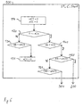
- Fig. 6 shows the first state 100, which immediately the The initial position of the controller behavior is displayed.
- this state 100 is in the essentially an activation or deactivation of countermeasures against the occurring Rattems performed.
- a first block 110 two Parameters toCT and zCC set to zero.
- a Parameter SCA which can be either logical 0 or 1, set to 0. Is not this If so, a rat is detected and countermeasures are activated.
- a block 130 the current vehicle speed vfz with a Comparison value vRCS compared.
- the current speed vfz with a compared to other limit vCD If the speed is less than this value, so in a block 150, the rotor acceleration, i. the gradient the monitored rotor speed (see Fig. 3 RDZ), determined and with a first Limit nACG compared. Exceeds the positive rotor acceleration RB this limit, it is changed to the second state 200. Otherwise follows a block 151 in which the negative rotor acceleration -RB with this Limit value is compared. If the negative rotor acceleration -RB is greater than this limit is, is changed to the third state 300.
- the rotor acceleration i. the gradient the monitored rotor speed (see Fig. 3 RDZ)
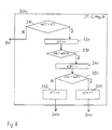
- the second state is described in more detail with reference to FIG. 7: It describes the Chatter detection based on the positive gradient of the rotor speed, ie the positive rotor acceleration. Essentially, it is based on a count variable zCPC determines whether the gradient occurs consecutively several times, so that on a periodic fluctuation of the rotor speed can be concluded, which is typical of the unstable state.
- the 25 km / h for example, no chatter detection is carried out (see FIG. Block 140).
- a predetermined Maximum speed vRCS e.g. 40 km / h may be the countermeasure interrupted (see block 130).
- the determined vehicle speed plays still an important role during the implementation of the countermeasures (see Fig. 3, Characteristic function ARK depending on the speed vfZ).
- the invention comprises very specific and exactly coordinated measures.
- the basic principle of the invention can also be realized by various other embodiments.
- the measures according to the invention aim at reducing rotor inertia in the case of an unstable state to increase significantly and thus the rattle too eliminate, which the ride comfort is significantly improved.
Landscapes
- Engineering & Computer Science (AREA)
- Chemical & Material Sciences (AREA)
- Combustion & Propulsion (AREA)
- Transportation (AREA)
- Mechanical Engineering (AREA)
- Steering Control In Accordance With Driving Conditions (AREA)
- Power Steering Mechanism (AREA)
Abstract
Description
- Fig. 1
- zeigt den Aufbau einer Motorregelung für eine herkömmliche Hilfskraftlenkung, bei der keine Unterdrückung des Ratterns erfolgt;
- Fig. 2
- zeigt in drei Teilausschnitten Eingangsmodule für diese Regelung;
- Fig. 3
- zeigt den Aufbau eines zur Unterdrückung des Ratterns erfindungsgemäß ausgestalteten Eingangsmoduls für einen PD-Regler;
- Fig. 3
- zeigt den Aufbau eines erfindungsgemäß ausgestalteten Eingangsmoduls zur Unterdrückung des Ratterns;
- Fig. 4
- zeigt den Aufbau eines erfindungsgemäß zusätzlich mit einem Filter ausgestatteten Eingangsmoduls zur Verbesserung der Unterdrückung des Rattems;
- Fig. 5
- zeigt in näheren Details den Aufbau dieses Filters;
- Fig. 6 - 8
- zeigen jeweils einen von drei Zuständen für einen in die erfindungsgemäße Regelung eingebundenen Zustandautomaten.
Claims (14)
- Fahrzeug-Hilfskraftlenkung mit Elektromotor und mit einer elektronischen Regelung (PDR), die den Elektromotor dynamisch steuert, so dass dieser zusätzlich zu dem vom Fahrer des Fahrzeuges aufgebrachten Lenkmoment (LM) ein lenkkraftunterstützendes Motormoment (MSM) erzeugt,
dadurch gekennzeichnet, dass
die Regelung (PDR) die Rotordrehzahl (RDZ) des Rotors des Elektromotors auswertet und die dynamische Trägheit des Rotors erhöht, falls die Auswertung der Rotordrehzahl (RDZ) einen instabilen Zustand der Regelung anzeigt. - Fahrzeug-Hilfskraftlenkung nach Anspruch 1, dadurch gekennzeichnet, dass der Elektromotor ein Asynchronmotor ist und dass die Regelung (PDR) im instabilen Zustand die dynamische Trägheit des Rotors mittels einer feldorientierten Steuerung des Asynchronmotors erhöht.
- Fahrzeug-Hilfskraftlenkung nach Anspruch 1, dadurch gekennzeichnet, dass die Regelung (PDR) die Fahrzeuggeschwindigkeit (vfz) überwacht und die Rotordrehzahl (RDZ) nur dann auswertet, um den instabilen Zustand zu erkennen, wenn die Fahrgeschwindigkeit einen ersten vorgebbaren Wert (vCD) nicht überschreitet.
- Fahrzeug-Hilfskraftlenkung nach Anspruch 1, dadurch gekennzeichnet, dass die Regelung (PDR) die Rotordrehzahl (RDZ) auswertet, indem sie die zeitliche Änderung der Rotordrehzahl überwacht, und dass die Regelung (PDR) den instabilen Zustand erkennt, falls die Rotordrehzahl (RDZ) zumindest über einen vorgebbaren Zeitraum hin einer periodisch schwankt, insbesondere mit einer Frequenz schwankt, die innerhalb eines vorgebbaren Bereichs liegt.
- Fahrzeug-Hilfskraftlenkung nach Anspruch 1, dadurch gekennzeichnet, dass die Regelung (PDR) die Fahrzeuggeschwindigkeit (vfz) überwacht und im instabilen Zustand der Regelung die dynamische Trägheit des Rotors nur dann erhöht, wenn die Fahrzeuggeschwindigkeit (vfz) einen zweiten vorgebbaren Wert (vRCS) nicht überschreitet.
- Fahrzeug-Hilfskraftlenkung nach Anspruch 1, dadurch gekennzeichnet, dass die Regelung (PDR) im stabilen Zustand der Regelung die dynamische Trägheit des Rotors verringert, indem sie die dynamische Steuerung des Elektromotors mit einem ersten Faktor (RTF1) beaufschlagt, der ein positives Vorzeichen hat, und dass die Regelung (PDR) im instabilen Zustand der Regelung die dynamische Trägheit des Rotors erhöht, indem sie die dynamische Steuerung des Elektromotors mit einem zweiten Faktor (RTF2) beaufschlagt, der kleiner als der erste Faktor (RTF1) ist und/oder der ein negatives Vorzeichen hat.
- Fahrzeug-Hilfskraftlenkung nach Anspruch 6, dadurch gekennzeichnet, dass die Regelung (PDR) die Fahrzeuggeschwindigkeit (vfz) überwacht und den negativen Faktor (RTF2) mittels einer Kennlinien-Funktion (ARK) ermittelt, die zumindest von der Fahrzeuggeschwindigkeit (vfz), insbesondere von der Fahrzeuggeschwindigkeit (vfz), der Rotordrehzahl (RDZ) und einem Vorzeichenwechsel des Lenkmoments (LM), abhängig ist.
- Fahrzeug-Hilfskraftlenkung nach Anspruch 1, dadurch gekennzeichnet, dass die Regelung ein PD-Regler (PDR) ist, der mindestens ein Proportionalglied und mindestens ein Differentialglied aufweist, dass der PD-Regler (PDR) den Elektromotor anhand einer durch sein Proportionalglied vorgegebenen Kennlinienfunktion (SAKL) steuert und dass der PD-Regler (PDR) im instabilen Zustand die Kennlinienfunktion (SAKL) mit einer zeitverzögernden Filterfunktion (ARF) beaufschlagt.
- Verfahren zur Regelung eines Elektromotors in einer Fahrzeug-Hilfskraftlenkung, . bei dem der Elektromotor dynamisch gesteuert wird, so dass dieser zusätzlich zu dem vom Fahrer des Fahrzeuges aufgebrachten Lenkmoment (LM) ein lenkkraftunterstützendes Motormoment (MSM) erzeugt,
dadurch gekennzeichnet, dass
die Rotordrehzahl (RDZ) des Rotors des Elektromotors auswertet wird und dass die dynamische Trägheit des Rotors erhöht wird, falls die Auswertung der Rotordrehzahl (RDZ) einen instabilen Zustand der Regelung anzeigt. - Verfahren nach Anspruch 9, dadurch gekennzeichnet, dass
das Verfahren anhand eines Zustandsautomaten durchgeführt wird, der drei Zustände (100, 200, 300) umfasst, wobei der erste Zustand (100) eingenommen wird, um das Erkennen des instabilen Zustandes der Regelung zu aktivieren oder zu deaktivieren, wobei der zweite oder dritte Zustand (200; 300) eingenommen wird, um die Auswertung der Rotordrehzahl (RDZ) zum Erkennen des instabilen Zustandes durchzuführen. - Verfahren nach Anspruch 10, dadurch gekennzeichnet, dass
in dem ersten Zustand (100) die Fahrzeuggeschwindigkeit (vfz) überwacht wird und dass zum Erkennen des instabilen Zustandes in den zweiten oder dritten Zustand (200; 300) gewechselt wird, falls die Fahrzeuggeschwindigkeit (vfz) einen vorgebbaren ersten Wert (vCD) überschreitet, wobei aus der zeitlichen Änderung der Rotordrehzahl die positive bzw. negative Rotorbeschleunigung (RB ; - RB) ermittelt und mit einem Gradientengrenzwert (nACG) verglichen wird, wobei in den zweiten Zustand (200) gewechselt wird, falls die positive Rotorbeschleunigung (RB) den Gradientengrenzwert (nACG) überschreitet, und wobei in den dritten Zustand (300) gewechselt wird, falls die negative Rotorbeschleunigung (- RB) den Gradientengrenzwert (nACG) überschreitet. - Verfahren nach Anspruch 10, dadurch gekennzeichnet, dass
in dem ersten Zustand (100) die Fahrzeuggeschwindigkeit (vfz) überwacht wird und das Erkennen des instabilen Zustandes deaktiviert wird (sCA=0), falls die Fahrzeuggeschwindigkeit (vfz) einen vorgebbaren zweiten Wert (vRCS) überschreitet. - Verfahren nach Anspruch 11, dadurch gekennzeichnet, dass
in dem zweiten Zustand (200) die negative Rotorbeschleunigung (-RB) mit dem Gradientengrenzwert (nAVG) verglichen wird und geprüft wird, ob dieser Gradientengrenzwert (nAVG) weniger häufig als eine vorgebbaren Anzahl (zCPC) überschritten wird und, falls dies der Fall ist, in den ersten Zustand (100) gewechselt wird, um die Erkennung des instabilen Zustandes zu deaktivieren (sCA = 1) oder, falls dies nicht der Fall ist, in den dritten Zustand (300) gewechselt wird. - Verfahren nach Anspruch 11, dadurch gekennzeichnet, dass
in dem dritten Zustand (300) die positive Rotorbeschleunigung (RB) mit dem Gradientengrenzwert (nAVG) verglichen wird und geprüft wird, ob dieser Gradientengrenzwert (nAVG) weniger häufig als eine vorgebbaren Anzahl (zCPC) überschritten wird und, falls dies der Fall ist, in den ersten Zustand (100) gewechselt wird, um die Erkennung des instabilen Zustandes zu deaktivieren (sCA = 1) oder, falls dies nicht der Fall ist, in den zweiten Zustand (200) gewechselt wird.
Applications Claiming Priority (2)
| Application Number | Priority Date | Filing Date | Title |
|---|---|---|---|
| DE10351485A DE10351485A1 (de) | 2003-11-04 | 2003-11-04 | Fahrzeug-Hilfskraftlenkung mit Elektromotor |
| DE10351485 | 2003-11-04 |
Publications (2)
| Publication Number | Publication Date |
|---|---|
| EP1529716A1 true EP1529716A1 (de) | 2005-05-11 |
| EP1529716B1 EP1529716B1 (de) | 2007-06-06 |
Family
ID=34428557
Family Applications (1)
| Application Number | Title | Priority Date | Filing Date |
|---|---|---|---|
| EP04023467A Expired - Lifetime EP1529716B1 (de) | 2003-11-04 | 2004-10-01 | Fahrzeug-Hilfskraftlenkung mit Elektromotor |
Country Status (3)
| Country | Link |
|---|---|
| US (1) | US7383109B2 (de) |
| EP (1) | EP1529716B1 (de) |
| DE (2) | DE10351485A1 (de) |
Families Citing this family (6)
| Publication number | Priority date | Publication date | Assignee | Title |
|---|---|---|---|---|
| JP4617716B2 (ja) * | 2004-05-11 | 2011-01-26 | 株式会社ジェイテクト | 電動パワーステアリング装置 |
| US7715964B1 (en) * | 2005-05-10 | 2010-05-11 | Trimble Navigation, Ltd. | Very low speed vehicle control algorithm operating in the spatial domain |
| DE102012112484B4 (de) * | 2012-12-18 | 2021-02-25 | Robert Bosch Gmbh | Verfahren zum Betreiben eines Lenksystems eines Kraftfahrzeugs |
| DE102017215842B4 (de) * | 2017-09-08 | 2025-01-16 | Robert Bosch Gmbh | Verfahren zum Betrieb einer Lenkvorrichtung und Lenkvorrichtung |
| DE102018123410A1 (de) * | 2018-09-24 | 2020-03-26 | Minebea Mitsumi Inc. | Verfahren und Vorrichtung zur Überwachung einer Motorsteuerung |
| CN119294272B (zh) * | 2024-12-12 | 2025-03-11 | 青岛智和精密科技有限公司 | 一种用于力矩电机驱动系统的稳定性分析方法及系统 |
Citations (4)
| Publication number | Priority date | Publication date | Assignee | Title |
|---|---|---|---|---|
| EP1138578A2 (de) * | 2000-03-29 | 2001-10-04 | Toyoda Koki Kabushiki Kaisha | Steuereinheit für eine elektrische Servolenkung |
| US20030019687A1 (en) * | 2001-07-28 | 2003-01-30 | Ford Motor Company | Power steering system with vehicle braking state input for vibration reduction |
| EP1302385A2 (de) * | 2001-10-11 | 2003-04-16 | Delphi Technologies, Inc. | Vorrichtung und Verfahren zur Erzeugung einer kompensierten Motorgeschwindigkeitsausgangsgrösse der Krafteinheit einer elektrischen Hilfskraftlenkung |
| US20030107339A1 (en) * | 2001-12-06 | 2003-06-12 | Honda Giken Kogyo Kabushiki Kaisha | Electric power steering apparatus |
Family Cites Families (9)
| Publication number | Priority date | Publication date | Assignee | Title |
|---|---|---|---|---|
| JPS59130780A (ja) * | 1983-01-17 | 1984-07-27 | Aisin Seiki Co Ltd | 電動パワ−ステアリング装置 |
| FR2577878B1 (fr) * | 1985-02-26 | 1989-03-31 | Honda Motor Co Ltd | Dispositif de direction assiste par un moteur |
| CA1280375C (en) * | 1986-01-14 | 1991-02-19 | Yasuo Shimizu | Motor-driven power steering system for vehicles |
| JPH0796386B2 (ja) | 1986-02-07 | 1995-10-18 | カヤバ工業株式会社 | 電動式パワ−ステアリング装置 |
| JPH06211152A (ja) * | 1993-01-19 | 1994-08-02 | Aisin Seiki Co Ltd | 車輌の操舵装置 |
| US5623409A (en) * | 1994-10-31 | 1997-04-22 | Trw Inc. | Method and apparatus for non-linear damping of an electric assist steering system for vehicle yaw rate control |
| IT1297070B1 (it) * | 1997-11-21 | 1999-08-03 | Micronasa Di Patarchi Alberto | Macchina dinamoelettrica rotante a induzione elettromagnetica come agente in motori elettrici lineari. |
| JP2003502584A (ja) * | 1998-11-03 | 2003-01-21 | ルーク ラメレン ウント クツプルングスバウ ベタイリグングス コマンディートゲゼルシャフト | 変速意図識別機能を備えた自動車 |
| JP3371889B2 (ja) * | 2000-04-17 | 2003-01-27 | トヨタ自動車株式会社 | 車両のスリップ制御 |
-
2003
- 2003-11-04 DE DE10351485A patent/DE10351485A1/de not_active Withdrawn
-
2004
- 2004-10-01 EP EP04023467A patent/EP1529716B1/de not_active Expired - Lifetime
- 2004-10-01 DE DE502004004017T patent/DE502004004017D1/de not_active Expired - Lifetime
- 2004-11-04 US US10/983,196 patent/US7383109B2/en not_active Expired - Lifetime
Patent Citations (4)
| Publication number | Priority date | Publication date | Assignee | Title |
|---|---|---|---|---|
| EP1138578A2 (de) * | 2000-03-29 | 2001-10-04 | Toyoda Koki Kabushiki Kaisha | Steuereinheit für eine elektrische Servolenkung |
| US20030019687A1 (en) * | 2001-07-28 | 2003-01-30 | Ford Motor Company | Power steering system with vehicle braking state input for vibration reduction |
| EP1302385A2 (de) * | 2001-10-11 | 2003-04-16 | Delphi Technologies, Inc. | Vorrichtung und Verfahren zur Erzeugung einer kompensierten Motorgeschwindigkeitsausgangsgrösse der Krafteinheit einer elektrischen Hilfskraftlenkung |
| US20030107339A1 (en) * | 2001-12-06 | 2003-06-12 | Honda Giken Kogyo Kabushiki Kaisha | Electric power steering apparatus |
Also Published As
| Publication number | Publication date |
|---|---|
| DE502004004017D1 (de) | 2007-07-19 |
| EP1529716B1 (de) | 2007-06-06 |
| US20050096813A1 (en) | 2005-05-05 |
| DE10351485A1 (de) | 2005-06-09 |
| US7383109B2 (en) | 2008-06-03 |
Similar Documents
| Publication | Publication Date | Title |
|---|---|---|
| DE19902516B4 (de) | Regler für ein elektrisches Servolenksystem | |
| DE19536989B4 (de) | Lenksteuersystem für ein Fahrzeug | |
| DE112013003863B4 (de) | Vorrichtung und Verfahren zum Steuern eines Servolenksystems | |
| DE60115169T2 (de) | System und verfahren zur Unterstützung beim Folgen einer Fahrspur für ein Fahrzeug | |
| DE19527334B4 (de) | Fahrzeug-Lenksteuersystem | |
| DE60308075T2 (de) | Automatische Lenkeinrichtung für ein Fahrzeug und Steuerverfahren dafür | |
| DE69508179T2 (de) | Elektrische Servolenkung | |
| DE60319497T2 (de) | Fahrzeuglenksystem mit integrierter Rückkopplungsregelung | |
| DE3855655T2 (de) | Gierkontrolleinrichtung für ein Fahrzeug | |
| DE3819474C1 (de) | ||
| EP3738860B1 (de) | Verfahren und lenkungssteuergerät zum ermitteln einer stellgrösse für das einstellen eines servolenkmoments bei einem fahrzeuglenksystem | |
| DE112013006873B4 (de) | Fahrzeuglenksteuervorrichtung | |
| DE69624737T2 (de) | Hydraulische Servolenkung | |
| DE69502439T2 (de) | Steuerung für eine elektrische Servolenkung | |
| DE112007000094B4 (de) | Fahrzeuglenksteuerungsvorrichtung | |
| DE19822170C2 (de) | Servolenkvorrichtung | |
| DE102017121809B4 (de) | Steuergerät für das Verhalten eines Fahrzeugs | |
| DE19919797A1 (de) | Elektrisches Servolenkungssystem | |
| DE69622356T2 (de) | Lenkungssteuerung mit Lenkdrehmoment-Hysterese | |
| DE102017126015B4 (de) | Lenkungssystem mit spannungskompensiertem antiaufholungsalgorithmus | |
| DE102011052881A1 (de) | Verfahren zur Bestimmung einer Zahnstangenkraft für eine Lenkvorrichtung in einem Fahrzeug, Lenkvorrichtung und Steuer- und/oder Regeleinrichtung für eine Lenkvorrichtung | |
| DE102016218424B4 (de) | Fahrerassistenzsystem | |
| DE102009026497A1 (de) | Verfahren zum Erkennen interner Reibung in einem Lenksystem | |
| DE10035356B4 (de) | Vorrichtung zur elektrischen Servolenkung | |
| DE102005024125B4 (de) | Lenkeinrichtung und Lenkverhältnissteuerverfahren für Kraftfahrzeuge |
Legal Events
| Date | Code | Title | Description |
|---|---|---|---|
| PUAI | Public reference made under article 153(3) epc to a published international application that has entered the european phase |
Free format text: ORIGINAL CODE: 0009012 |
|
| AK | Designated contracting states |
Kind code of ref document: A1 Designated state(s): AT BE BG CH CY CZ DE DK EE ES FI FR GB GR HU IE IT LI LU MC NL PL PT RO SE SI SK TR |
|
| AX | Request for extension of the european patent |
Extension state: AL HR LT LV MK |
|
| 17P | Request for examination filed |
Effective date: 20050713 |
|
| AKX | Designation fees paid |
Designated state(s): DE ES FR GB IT SE |
|
| 17Q | First examination report despatched |
Effective date: 20061122 |
|
| GRAP | Despatch of communication of intention to grant a patent |
Free format text: ORIGINAL CODE: EPIDOSNIGR1 |
|
| GRAS | Grant fee paid |
Free format text: ORIGINAL CODE: EPIDOSNIGR3 |
|
| GRAA | (expected) grant |
Free format text: ORIGINAL CODE: 0009210 |
|
| AK | Designated contracting states |
Kind code of ref document: B1 Designated state(s): DE ES FR GB IT SE |
|
| REG | Reference to a national code |
Ref country code: GB Ref legal event code: FG4D Free format text: NOT ENGLISH |
|
| REF | Corresponds to: |
Ref document number: 502004004017 Country of ref document: DE Date of ref document: 20070719 Kind code of ref document: P |
|
| REG | Reference to a national code |
Ref country code: SE Ref legal event code: TRGR |
|
| PG25 | Lapsed in a contracting state [announced via postgrant information from national office to epo] |
Ref country code: ES Free format text: LAPSE BECAUSE OF FAILURE TO SUBMIT A TRANSLATION OF THE DESCRIPTION OR TO PAY THE FEE WITHIN THE PRESCRIBED TIME-LIMIT Effective date: 20070917 |
|
| ET | Fr: translation filed | ||
| GBV | Gb: ep patent (uk) treated as always having been void in accordance with gb section 77(7)/1977 [no translation filed] |
Effective date: 20070606 |
|
| PLBE | No opposition filed within time limit |
Free format text: ORIGINAL CODE: 0009261 |
|
| STAA | Information on the status of an ep patent application or granted ep patent |
Free format text: STATUS: NO OPPOSITION FILED WITHIN TIME LIMIT |
|
| PG25 | Lapsed in a contracting state [announced via postgrant information from national office to epo] |
Ref country code: GB Free format text: LAPSE BECAUSE OF FAILURE TO SUBMIT A TRANSLATION OF THE DESCRIPTION OR TO PAY THE FEE WITHIN THE PRESCRIBED TIME-LIMIT Effective date: 20070606 |
|
| 26N | No opposition filed |
Effective date: 20080307 |
|
| PGFP | Annual fee paid to national office [announced via postgrant information from national office to epo] |
Ref country code: IT Payment date: 20101016 Year of fee payment: 7 |
|
| PGFP | Annual fee paid to national office [announced via postgrant information from national office to epo] |
Ref country code: FR Payment date: 20111103 Year of fee payment: 8 Ref country code: SE Payment date: 20111011 Year of fee payment: 8 |
|
| REG | Reference to a national code |
Ref country code: FR Ref legal event code: ST Effective date: 20130628 |
|
| PG25 | Lapsed in a contracting state [announced via postgrant information from national office to epo] |
Ref country code: SE Free format text: LAPSE BECAUSE OF NON-PAYMENT OF DUE FEES Effective date: 20121002 |
|
| PG25 | Lapsed in a contracting state [announced via postgrant information from national office to epo] |
Ref country code: IT Free format text: LAPSE BECAUSE OF NON-PAYMENT OF DUE FEES Effective date: 20121001 Ref country code: FR Free format text: LAPSE BECAUSE OF NON-PAYMENT OF DUE FEES Effective date: 20121031 |
|
| REG | Reference to a national code |
Ref country code: DE Ref legal event code: R081 Ref document number: 502004004017 Country of ref document: DE Owner name: ROBERT BOSCH AUTOMOTIVE STEERING GMBH, DE Free format text: FORMER OWNER: ZF LENKSYSTEME GMBH, 73527 SCHWAEBISCH GMUEND, DE Effective date: 20150423 |
|
| REG | Reference to a national code |
Ref country code: DE Ref legal event code: R084 Ref document number: 502004004017 Country of ref document: DE |
|
| REG | Reference to a national code |
Ref country code: DE Ref legal event code: R081 Ref document number: 502004004017 Country of ref document: DE Owner name: ROBERT BOSCH GMBH, DE Free format text: FORMER OWNER: ROBERT BOSCH AUTOMOTIVE STEERING GMBH, 73527 SCHWAEBISCH GMUEND, DE |
|
| PGFP | Annual fee paid to national office [announced via postgrant information from national office to epo] |
Ref country code: DE Payment date: 20211214 Year of fee payment: 18 |
|
| REG | Reference to a national code |
Ref country code: DE Ref legal event code: R119 Ref document number: 502004004017 Country of ref document: DE |
|
| PG25 | Lapsed in a contracting state [announced via postgrant information from national office to epo] |
Ref country code: DE Free format text: LAPSE BECAUSE OF NON-PAYMENT OF DUE FEES Effective date: 20230503 |