EP1529708B1 - Fenêtre basculante pour véhicules ferroviaires avec basculement complet et enlèvement en cas de situations d'urgence - Google Patents
Fenêtre basculante pour véhicules ferroviaires avec basculement complet et enlèvement en cas de situations d'urgence Download PDFInfo
- Publication number
- EP1529708B1 EP1529708B1 EP04425608A EP04425608A EP1529708B1 EP 1529708 B1 EP1529708 B1 EP 1529708B1 EP 04425608 A EP04425608 A EP 04425608A EP 04425608 A EP04425608 A EP 04425608A EP 1529708 B1 EP1529708 B1 EP 1529708B1
- Authority
- EP
- European Patent Office
- Prior art keywords
- pins
- tiltable portion
- window
- tiltable
- integral
- Prior art date
- Legal status (The legal status is an assumption and is not a legal conclusion. Google has not performed a legal analysis and makes no representation as to the accuracy of the status listed.)
- Expired - Lifetime
Links
- 239000011521 glass Substances 0.000 description 9
- 238000004378 air conditioning Methods 0.000 description 4
- 230000006378 damage Effects 0.000 description 2
- 208000027418 Wounds and injury Diseases 0.000 description 1
- 231100001261 hazardous Toxicity 0.000 description 1
- 208000014674 injury Diseases 0.000 description 1
- 238000012423 maintenance Methods 0.000 description 1
- 238000012986 modification Methods 0.000 description 1
- 230000004048 modification Effects 0.000 description 1
- 230000000284 resting effect Effects 0.000 description 1
- 238000005096 rolling process Methods 0.000 description 1
Images


Classifications
-
- E—FIXED CONSTRUCTIONS
- E05—LOCKS; KEYS; WINDOW OR DOOR FITTINGS; SAFES
- E05C—BOLTS OR FASTENING DEVICES FOR WINGS, SPECIALLY FOR DOORS OR WINDOWS
- E05C17/00—Devices for holding wings open; Devices for limiting opening of wings or for holding wings open by a movable member extending between frame and wing; Braking devices, stops or buffers, combined therewith
-
- B—PERFORMING OPERATIONS; TRANSPORTING
- B61—RAILWAYS
- B61D—BODY DETAILS OR KINDS OF RAILWAY VEHICLES
- B61D25/00—Window arrangements peculiar to rail vehicles
-
- E—FIXED CONSTRUCTIONS
- E05—LOCKS; KEYS; WINDOW OR DOOR FITTINGS; SAFES
- E05B—LOCKS; ACCESSORIES THEREFOR; HANDCUFFS
- E05B65/00—Locks or fastenings for special use
- E05B65/10—Locks or fastenings for special use for panic or emergency doors
- E05B65/1033—Locks or fastenings for special use for panic or emergency doors emergency release of windows, window grills, escape hatches or the like
-
- E—FIXED CONSTRUCTIONS
- E05—LOCKS; KEYS; WINDOW OR DOOR FITTINGS; SAFES
- E05C—BOLTS OR FASTENING DEVICES FOR WINGS, SPECIALLY FOR DOORS OR WINDOWS
- E05C19/00—Other devices specially designed for securing wings, e.g. with suction cups
- E05C19/006—Other devices specially designed for securing wings, e.g. with suction cups by displacement of the wing substantially in its own plane
Definitions
- the present invention relates in general to fittings for rolling stock. More particularly the invention relates to a window with opening of the tiltable type for railway carriages, designed to be tipped up and also, if necessary, removed in the event of an emergency.
- US 2003/0107221 A1 discloses a window according to the preamble of claim 1.
- the object of the present invention is to avoid the disadvantages described above by providing a window for railway carriages with opening of the tiltable type and which, if required, can be tipped up completely and possibly removed to provide an adequate aperture for evacuating passengers without the need to smash any window.
- a window according to the subject-matter of claim 1 such a window with a hinge opening for railway carriages whose characteristic feature consists in that the tiltable portion is hinged to the surround of the window by means of a pair of aligned and axially sliding pins so as to define a first position wherein they are engaged in housings integral with the surround, and a second position wherein, following axial translation one towards the other, they are disengaged therefrom.
- the tiltable portion is also hinged, parallel to the pair of pins, to an intermediate cross member of the window integral with the surround, so that, when the pins are in the first position, the tiltable portion can only perform an angular movement of preset extent after the locking means have been disabled manually, whereas, when they are placed in the second position, the tiltable portion can rotate in relation to the cross member until it is fully tipped up, the locking means being disabled following lowering of the tiltable portion as a result of disengaging of the ends of the pins from the respective housings.
- 1 denotes generically a window of a railway carriage, which window is formed by a fixed window portion 2 and by a tiltable window portion 3 normally locked in a closed position and which can be released by staff on duty using the locks 4 situated in the upper part thereof by means of a special key for allowing limited opening of the window in the case wherein the air-conditioning of the carriage is not in operation.
- the structure of the window is, as a whole, of the conventional type and comprises a surround denoted by 5 and formed by an external part 5a for resting on the window-space formed in the side wall of the carriage, and an internal part 5b projecting internally from the outside one and acting as a support for a glass 7 of the fixed portion 2 of the window and as an abutment for the tiltable portion 3.
- the latter is in turn formed by a pane of glass 8 bordered around the perimeter by a frame 9 hinged to a transverse structure 10, whereto the lower pane of glass 7 is also attached.
- the transverse structure 10 is formed by a cross member or section bar 11 with a substantially H shape for bordering below a groove tightly housing the upper edge of the glass 7.
- the lower edge 9a of the frame 9, wherein the corresponding lower edge of the glass 8 is tightly housed, is engaged on a pair of pins 12a and 12b, coaxial and aligned one with the other and around which the frame 9 can rotate, allowing tiltable opening of the window.
- the two pins 12a,b are slidingly engaged in bushings 13 integral with the lower edge 9a of the frame 9 and, at the ends of the cross member 11, in respective housings 14 (only one is shown in the drawings) formed in support blocks 15 attached by means of screws 16 to the inner part 11a of the H-shaped cross member 11.
- an actuation device is provided, more particularly a crank mechanism with manual actuation integral with a profile 23 and connected to the two opposite ends of the pins 12a,b. More specifically, the free ends of the two pins 12a and 12b are connected to a disk 19 by means of respective connecting rods 17 and 18, which are connected eccentrically and at diametrically opposite parts to said disk 19. Disk 19 is integral with a stem 20 pivotally supported by the profile 23 and emerging frontally therefrom with one of its heads 20a set up for actuation by means of a special key.
- the cross member 11 is connected by means of a hinge 22 to the profile 23, extending inside the same cross member 11.
- two shoulders 24 are attached (only one can be seen in the drawings), wherein a slot 25 is formed at the housings 14 of the blocks 15 whereto the shoulders 24 are adjacent.
- the profile 23 has at least two intermediate apertures 26 (only one can be seen in the drawings) with the function which is to be described herein below.
- a block 27 is attached to the pin 12a (the same applies for the pin 12b), wherefrom an appendage 28 extends (see also Figure 8 ), abutting on a ridge 23a of the profile 23.
- the appendage 28 also constitutes an abutment element for the edge 9a of the frame 9 when the latter and the glass 8 attached thereto are rotated around the pins 12a,b.
- the lower edge 9a of the frame 9 abuts on the appendage 28 on the opposite side to the ridge 23a of the profile 23, effectively limiting rotation of the frame 9 to a preset angle (denoted by ⁇ ).
- the slot 25 has a length longer than the diameter of the housing 14 and extends towards the profile 23, once the end of the pins 12a,b has disengaged from the relevant housing 14, said end goes to the base of the slot 25, causing lowering of the pins 12a,b and of the frame 9 integral thereto, while the appendage 28 is positioned in the aperture 26.
- the frame 9 is lowered automatically, once the ends of the pins 12a,b are disengaged from the housings 14, due to its own weight which automatically releases the frame from the locking devices denoted by 4 and situated in the upper part of the window.
- a third position of the pins 12a,b can be provided wherein they can also be withdrawn from the slots 25.
- This can be obtained by defining two different extents of rotation of the disk 19, corresponding to two different extents of sliding of the pins 12a,b. More particularly, with a first rotation, the pins 12a,b can be slid until they are disengaged from the housings 14 of the blocks 15 and with a second subsequent rotation, to be performed if the tiltable portion also has to be removed, the ends of the pins 12a,b can be disengaged from the slots 25 of the shoulders 24.
- Seals 29 and 30 are placed between the lower edge 9a of the frame 9 and the cross member 11 on one side and the profile 23 on the other.
- Figures 12 and 13 illustrate a different embodiment of the device for actuating axial sliding of the pins 12a and 12b around which the tiltable part 3 rotates.
- the disk 19, whereto the pins 12a,b are connected via the connecting rods 17 and 18, is integral with a lever 32, which can also be actuated by the user, if necessary, without having to wait for help by the staff in charge, provided with the special key for turning the disk 19.
- An elastic plate 31 with an overturned V portion which engages in the disk 19 prevents free rotation of the same disk and hence axial sliding of the pins 12a,b, maintaining the tiltable part 3 in a closed position.
- the possibility of rotation around the pins 12a,b of the tiltable portion 3 is controlled by the abutting of the lower edge 9a of its frame 9 on the appendage 28 of the block 27 integral with the pin 12a and, correspondingly, the pin 12b.
- a plate 34 with a projection 33 is attached laterally to the frame 9, holding the glass 8 of the window.
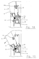
- Figure 14 illustrates the relative position of the angled edge 15a and of the projection 33 when the tiltable portion 3 is closed.
- Figure 18 illustrates the relative position of the two components when the tiltable portion 3 is open. In this condition the projection 33 abuts on the angled edge 15a, locking the tiltable portion in an open position with the preset slant.
- the window for railway carriages according to the present invention achieves in full the object set. It can in fact function as a normal window for air-conditioned carriages, since it can be locked in a closure position, and can be partially opened, in the case of non-functioning of the air-conditioning system, by actuating the locking devices 4 and rotating the tiltable portion 3 of the window 1 around the pins 12a,b.
- the window according to the invention also allows full tipping of the tiltable portion 3 in case emergency conditions should occur simply by actuating with a special key the stem head 20a placed centrally in relation to the window on the cross member 11, or by means of the lever 32, to disengage the ends of the pins 12a,b from the respective housings integral with the fixed structure. If considered necessary, it is also possible to provide for complete removal of the tiltable portion 3 of the window.
- the invention therefore allows emergency apertures through the windows to be provided without the need to smash the glass.
Landscapes
- Engineering & Computer Science (AREA)
- Mechanical Engineering (AREA)
- Business, Economics & Management (AREA)
- Emergency Management (AREA)
- Window Of Vehicle (AREA)
- Wing Frames And Configurations (AREA)
- Electric Propulsion And Braking For Vehicles (AREA)
- Aiming, Guidance, Guns With A Light Source, Armor, Camouflage, And Targets (AREA)
Claims (13)
- Fenêtre avec une ouverture de type basculante pour véhicules ferroviaires comprenant une partie basculante (3) montée pivotante par rapport à un encadrement (5) et des moyens (4) pour verrouiller ladite partie basculante dans une position fermée, caractérisée en ce que ladite partie basculante est montée pivotante par rapport au dit encadrement au moyen d'une paire de goupilles alignées et coulissantes axialement (12a, b) de façon à définir une première position, dans laquelle elles sont engagées dans des logements (14) réalisés dans ledit encadrement, et une seconde position dans laquelle, après une translation axiale l'une vers l'autre, elles sont sorties des logements, ladite partie basculante étant aussi montée pivotante, parallèlement à ladite paire de goupilles, par rapport à un élément transversal intermédiaire (11) de ladite fenêtre solidaire du dit encadrement (5), de façon que, lorsque lesdites goupilles sont dans leur première position, ladite partie basculante peut seulement effectuer un mouvement angulaire d'une amplitude préréglée après que lesdits moyens de verrouillage aient été débloqués manuellement, et que, lorsqu'elles sont dans leur seconde position, ladite partie basculante pivote par rapport au dit élément transversal (11) jusqu'à ce qu'elle soit complètement basculée, lesdits moyens de verrouillage étant débloqués après que ladite partie basculante ait été abaissée à cause de la sortie des extrémités des goupilles (12a, b) hors des logements respectifs (14).
- Fenêtre selon la revendication 1, dans laquelle ladite paire de goupilles est reliée en coulissement au bord inférieur (9a) de ladite partie basculante (3) et est couplée à un dispositif (17, 18, 19, 32) pour actionner leur mouvement de coulissement axial l'une vers l'autre et réciproquement.
- Fenêtre selon la revendication 2, dans laquelle ledit dispositif comprend un mécanisme à cames actionné manuellement (17, 18, 19, 32) intégré dans un profilé (23) monté rotatif par rapport au dit élément transversal (11) et relié aux deux extrémités opposées des dites goupilles (12a, b).
- Fenêtre selon la revendication 3, dans laquelle le mécanisme à cames comprend un corps en forme de disque (19) solidaire d'une tige (20) supportée par un profilé (23) monté pivotant par rapport au dit élément transversal (11), relié de façon excentrée à deux barres de connexion (17, 18) dans une position sensiblement diamétrale, lesdites barres de connexion étant à leur tour reliées aux extrémités opposées des dites goupilles (12a, b), ledit mécanisme à cames étant accessible via une tête de ladite tige pour actionnement au moyen d'une clé spéciale.
- Fenêtre selon la revendication 3, dans laquelle ledit mécanisme à cames comprend un corps en forme de disque (19) solidaire d'une tige (20) supportée par un profilé (23) monté pivotant par rapport au dit élément transversal (11), relié de façon excentrée à deux tiges de connexion (17, 18) dans une position sensiblement diamétrale, lesdites tiges de connexion étant à leur tour reliées aux extrémités opposées des dites goupilles (12a, b), ladite tige étant solidaire d'un levier (32) accessible pour son actionnement.
- Fenêtre selon l'une des revendications 4 et 5, dans laquelle la rotation du dit corps en forme de disque (19) est soumise à une contrainte élastique.
- Fenêtre selon l'une quelconque des revendications précédentes, dans laquelle les autres extrémités des dites goupilles sont reliées en rotation et en coulissement à des supports (15) solidaires du dit élément transversal (11).
- Fenêtre selon l'une quelconque des revendications précédentes, dans laquelle ledit élément transversal (11) est réalisé dans une portion de barre en forme sensiblement de H, dans laquelle est positionné un profilé (23) qui y est monté pivotant et solidaire de ladite paire de goupilles (12a, b) via une paire d'épaulements d'extrémité (24) comportant des fentes respectives (25) dans lesquelles est engagée ladite paire de goupilles.
- Fenêtre selon l'une des revendications 7 et 8, dans laquelle lesdits supports (15), solidaire de ladite portion de barre (11), comportent des logements respectifs (14) pour les extrémités des dites goupilles (12a, b) alignés avec lesdites fentes des dits épaulements (24), la longueur des dites fentes étant supérieure au diamètre des dits logements, lesdites fentes s'étendant vers ledit profilé.
- Fenêtre selon la revendication 9, dans laquelle ledit profilé comporte une arête longitudinale (23a) et au moins deux ouvertures (26) qui coupent ladite arête, lesdites goupilles maintenant des éléments de butée respectifs (28) abutant contre ladite arête lorsque lesdites goupilles sont dans leur première position, le bord inférieur (9a) de ladite partie basculante abutant contre ledit élément de butée (28), sur le côté opposé à ladite arête (23a), après un mouvement angulaire limité de ladite partie basculante, lesdits éléments de butée pouvant être engagés dans lesdites ouvertures lorsque lesdites goupilles sont ladite seconde position et engagées dans les fentes des dits épaulements, de façon que ladite partie basculante puisse commander ledit profilé (23) en rotation au moyen des dits épaulements (24) autour de ladite portion de barre (11) jusqu'à ce qu'elle soit complètement basculée.
- Fenêtre selon l'une quelconque des revendications précédentes, dans laquelle les fentes (24) des dits épaulements sont fermées et ladite paire de goupilles est conçue pour prendre une troisième position dans laquelle les extrémités des dites goupilles sont également sorties des dites fentes pour permettre l'enlèvement de la partie basculante.
- Fenêtre selon l'une quelconque des revendications 1 à 10, dans laquelle lesdites fentes (24) sont ouvertes sur le dessus de façon que, une fois que ladite partie basculante ait été entièrement basculée, les extrémités de ladite paire de goupilles, dans ladite seconde position, peuvent être sorties des dites fentes pour enlever ladite partie basculante,
- Fenêtre selon l'une quelconque des revendications 1 à 9, dans laquelle ladite partie basculante (3) comprend un châssis (9), sur les côtés duquel est réalisée une partie en saillie (33), lesdits supports (15) s'étendant jusqu'à la hauteur de ladite partie en saillie (33) et ayant ici un bord en angle (15a), ladite partie en saillie abutant sur ledit bord en angle lorsque lesdites goupilles (12a, b) sont engagées sans les logements respectifs (14) des dits supports (15), de façon à limiter la rotation de ladite partie basculante, permettant en revanche la rotation de ladite partie basculante jusqu'à ce qu'elle soit basculée lorsque cette dernière est abaissée suite à la sortie des dites goupilles (12a, b) hors des logements respectifs (14).
Applications Claiming Priority (2)
| Application Number | Priority Date | Filing Date | Title |
|---|---|---|---|
| IT000285A ITFI20030285A1 (it) | 2003-11-05 | 2003-11-05 | Finestrino con apertura a vasistas, a ribaltamento totale e rimozione in situazioni di emergenza, per carrozze ferroviarie |
| ITFI20030285 | 2003-11-05 |
Publications (2)
| Publication Number | Publication Date |
|---|---|
| EP1529708A1 EP1529708A1 (fr) | 2005-05-11 |
| EP1529708B1 true EP1529708B1 (fr) | 2008-07-16 |
Family
ID=34430730
Family Applications (1)
| Application Number | Title | Priority Date | Filing Date |
|---|---|---|---|
| EP04425608A Expired - Lifetime EP1529708B1 (fr) | 2003-11-05 | 2004-08-04 | Fenêtre basculante pour véhicules ferroviaires avec basculement complet et enlèvement en cas de situations d'urgence |
Country Status (4)
| Country | Link |
|---|---|
| EP (1) | EP1529708B1 (fr) |
| AT (1) | ATE401224T1 (fr) |
| DE (1) | DE602004015044D1 (fr) |
| IT (1) | ITFI20030285A1 (fr) |
Families Citing this family (5)
| Publication number | Priority date | Publication date | Assignee | Title |
|---|---|---|---|---|
| US7758104B2 (en) * | 2007-02-13 | 2010-07-20 | Clark Equipment Company | Window arrangement for a construction vehicle |
| US8091955B2 (en) | 2009-04-16 | 2012-01-10 | Clark Equipment Company | Sliding window for work vehicle cab |
| CN101936114B (zh) * | 2010-05-10 | 2012-10-24 | 唐山轨道客车有限责任公司 | 铁路客车救援通道车窗 |
| FR3057842B1 (fr) * | 2016-10-26 | 2018-11-30 | Arianegroup Sas | Dispositif d'evacuation d'urgence de baies thermoplastiques |
| FR3108576B1 (fr) * | 2020-03-25 | 2022-04-01 | Saint Gobain | Systeme de fixation d’un vitrage lateral de moyen de transport avec un verrou |
Family Cites Families (3)
| Publication number | Priority date | Publication date | Assignee | Title |
|---|---|---|---|---|
| US2639790A (en) * | 1950-01-26 | 1953-05-26 | James G Reitzel | Emergency exit window |
| US4313280A (en) * | 1980-04-10 | 1982-02-02 | The Adams & Westlake Company | Quick opening latch arrangement for hinged vehicle windows |
| US6688659B2 (en) * | 2001-12-07 | 2004-02-10 | Atwood Mobile Products Inc. | Egress window latching mechanism |
-
2003
- 2003-11-05 IT IT000285A patent/ITFI20030285A1/it unknown
-
2004
- 2004-08-04 EP EP04425608A patent/EP1529708B1/fr not_active Expired - Lifetime
- 2004-08-04 AT AT04425608T patent/ATE401224T1/de not_active IP Right Cessation
- 2004-08-04 DE DE602004015044T patent/DE602004015044D1/de not_active Expired - Fee Related
Also Published As
| Publication number | Publication date |
|---|---|
| EP1529708A1 (fr) | 2005-05-11 |
| ITFI20030285A1 (it) | 2005-05-06 |
| DE602004015044D1 (de) | 2008-08-28 |
| ATE401224T1 (de) | 2008-08-15 |
Similar Documents
| Publication | Publication Date | Title |
|---|---|---|
| CN107662480B (zh) | 机动车辆及其车门铰链机构 | |
| EP1041229B1 (fr) | Système de verrouillage pour fenêtre de cabine | |
| EP2115252B1 (fr) | Ensemble de plaque de poussée | |
| EP2923019B1 (fr) | Charnière démontable avec un verrou de sécurité | |
| EP0999976A1 (fr) | Systeme pour issue de secours | |
| ES2258806T3 (es) | Sistema de bloqueo para ventana basculante y giratoria. | |
| US20080040978A1 (en) | Hinge/Tilt Window Driven by an Electric Motor and Comprising a Feed Chain | |
| EP1529708B1 (fr) | Fenêtre basculante pour véhicules ferroviaires avec basculement complet et enlèvement en cas de situations d'urgence | |
| US4844524A (en) | Curtainside truck trailer closure assembly | |
| JPH02124320A (ja) | 車両ルーフ | |
| US5433039A (en) | Two-way motor vehicle door | |
| JPH04212626A (ja) | 車両ルーフ | |
| US6932395B1 (en) | Window assembly with release mechanism | |
| ES2238977T3 (es) | Dispositivo de cierre para una puerta lateral de un vehiculo automovil y vehiculo equipado con dicho dispositivo. | |
| EP1870542B1 (fr) | Ensemble panneau | |
| ES2699915T3 (es) | Mecanismo de giro de seguridad | |
| JP4151564B2 (ja) | 横軸回転窓 | |
| HU223252B1 (hu) | Vasalat ablakokhoz és ajtókhoz | |
| KR100462401B1 (ko) | 열림각 조정이 가능한 도어체커 | |
| JP2005163529A (ja) | 横軸回転窓 | |
| NL2014770B1 (en) | Security device for a window. | |
| JP3885687B2 (ja) | ブラインド装置 | |
| JP4376024B2 (ja) | 作業車両におけるリヤサイドパネルの開閉機構 | |
| KR100369036B1 (ko) | 자동차의 윈도우글래스 비상열림장치 | |
| KR102314299B1 (ko) | 유지보수가 용이한 터널의 공동구 덮개 |
Legal Events
| Date | Code | Title | Description |
|---|---|---|---|
| PUAI | Public reference made under article 153(3) epc to a published international application that has entered the european phase |
Free format text: ORIGINAL CODE: 0009012 |
|
| AK | Designated contracting states |
Kind code of ref document: A1 Designated state(s): AT BE BG CH CY CZ DE DK EE ES FI FR GB GR HU IE IT LI LU MC NL PL PT RO SE SI SK TR |
|
| AX | Request for extension of the european patent |
Extension state: AL HR LT LV MK |
|
| 17P | Request for examination filed |
Effective date: 20050714 |
|
| AKX | Designation fees paid |
Designated state(s): AT BE BG CH CY CZ DE DK EE ES FI FR GB GR HU IE IT LI LU MC NL PL PT RO SE SI SK TR |
|
| GRAP | Despatch of communication of intention to grant a patent |
Free format text: ORIGINAL CODE: EPIDOSNIGR1 |
|
| GRAS | Grant fee paid |
Free format text: ORIGINAL CODE: EPIDOSNIGR3 |
|
| GRAA | (expected) grant |
Free format text: ORIGINAL CODE: 0009210 |
|
| AK | Designated contracting states |
Kind code of ref document: B1 Designated state(s): AT BE BG CH CY CZ DE DK EE ES FI FR GB GR HU IE IT LI LU MC NL PL PT RO SE SI SK TR |
|
| REG | Reference to a national code |
Ref country code: GB Ref legal event code: FG4D |
|
| REG | Reference to a national code |
Ref country code: CH Ref legal event code: EP |
|
| REF | Corresponds to: |
Ref document number: 602004015044 Country of ref document: DE Date of ref document: 20080828 Kind code of ref document: P |
|
| REG | Reference to a national code |
Ref country code: IE Ref legal event code: FG4D |
|
| NLV1 | Nl: lapsed or annulled due to failure to fulfill the requirements of art. 29p and 29m of the patents act | ||
| PG25 | Lapsed in a contracting state [announced via postgrant information from national office to epo] |
Ref country code: ES Free format text: LAPSE BECAUSE OF FAILURE TO SUBMIT A TRANSLATION OF THE DESCRIPTION OR TO PAY THE FEE WITHIN THE PRESCRIBED TIME-LIMIT Effective date: 20081027 Ref country code: NL Free format text: LAPSE BECAUSE OF FAILURE TO SUBMIT A TRANSLATION OF THE DESCRIPTION OR TO PAY THE FEE WITHIN THE PRESCRIBED TIME-LIMIT Effective date: 20080716 Ref country code: PT Free format text: LAPSE BECAUSE OF FAILURE TO SUBMIT A TRANSLATION OF THE DESCRIPTION OR TO PAY THE FEE WITHIN THE PRESCRIBED TIME-LIMIT Effective date: 20081216 |
|
| PG25 | Lapsed in a contracting state [announced via postgrant information from national office to epo] |
Ref country code: SI Free format text: LAPSE BECAUSE OF FAILURE TO SUBMIT A TRANSLATION OF THE DESCRIPTION OR TO PAY THE FEE WITHIN THE PRESCRIBED TIME-LIMIT Effective date: 20080716 Ref country code: FI Free format text: LAPSE BECAUSE OF FAILURE TO SUBMIT A TRANSLATION OF THE DESCRIPTION OR TO PAY THE FEE WITHIN THE PRESCRIBED TIME-LIMIT Effective date: 20080716 Ref country code: BG Free format text: LAPSE BECAUSE OF FAILURE TO SUBMIT A TRANSLATION OF THE DESCRIPTION OR TO PAY THE FEE WITHIN THE PRESCRIBED TIME-LIMIT Effective date: 20081016 Ref country code: AT Free format text: LAPSE BECAUSE OF FAILURE TO SUBMIT A TRANSLATION OF THE DESCRIPTION OR TO PAY THE FEE WITHIN THE PRESCRIBED TIME-LIMIT Effective date: 20080716 |
|
| PG25 | Lapsed in a contracting state [announced via postgrant information from national office to epo] |
Ref country code: MC Free format text: LAPSE BECAUSE OF NON-PAYMENT OF DUE FEES Effective date: 20080831 Ref country code: BE Free format text: LAPSE BECAUSE OF FAILURE TO SUBMIT A TRANSLATION OF THE DESCRIPTION OR TO PAY THE FEE WITHIN THE PRESCRIBED TIME-LIMIT Effective date: 20080716 |
|
| REG | Reference to a national code |
Ref country code: CH Ref legal event code: PL |
|
| PG25 | Lapsed in a contracting state [announced via postgrant information from national office to epo] |
Ref country code: EE Free format text: LAPSE BECAUSE OF FAILURE TO SUBMIT A TRANSLATION OF THE DESCRIPTION OR TO PAY THE FEE WITHIN THE PRESCRIBED TIME-LIMIT Effective date: 20080716 Ref country code: DK Free format text: LAPSE BECAUSE OF FAILURE TO SUBMIT A TRANSLATION OF THE DESCRIPTION OR TO PAY THE FEE WITHIN THE PRESCRIBED TIME-LIMIT Effective date: 20080716 |
|
| PLBE | No opposition filed within time limit |
Free format text: ORIGINAL CODE: 0009261 |
|
| STAA | Information on the status of an ep patent application or granted ep patent |
Free format text: STATUS: NO OPPOSITION FILED WITHIN TIME LIMIT |
|
| PG25 | Lapsed in a contracting state [announced via postgrant information from national office to epo] |
Ref country code: CZ Free format text: LAPSE BECAUSE OF FAILURE TO SUBMIT A TRANSLATION OF THE DESCRIPTION OR TO PAY THE FEE WITHIN THE PRESCRIBED TIME-LIMIT Effective date: 20080716 Ref country code: SK Free format text: LAPSE BECAUSE OF FAILURE TO SUBMIT A TRANSLATION OF THE DESCRIPTION OR TO PAY THE FEE WITHIN THE PRESCRIBED TIME-LIMIT Effective date: 20080716 Ref country code: RO Free format text: LAPSE BECAUSE OF FAILURE TO SUBMIT A TRANSLATION OF THE DESCRIPTION OR TO PAY THE FEE WITHIN THE PRESCRIBED TIME-LIMIT Effective date: 20080716 |
|
| 26N | No opposition filed |
Effective date: 20090417 |
|
| GBPC | Gb: european patent ceased through non-payment of renewal fee |
Effective date: 20081016 |
|
| PG25 | Lapsed in a contracting state [announced via postgrant information from national office to epo] |
Ref country code: CH Free format text: LAPSE BECAUSE OF NON-PAYMENT OF DUE FEES Effective date: 20080831 Ref country code: LI Free format text: LAPSE BECAUSE OF NON-PAYMENT OF DUE FEES Effective date: 20080831 |
|
| REG | Reference to a national code |
Ref country code: FR Ref legal event code: ST Effective date: 20090630 |
|
| PG25 | Lapsed in a contracting state [announced via postgrant information from national office to epo] |
Ref country code: IE Free format text: LAPSE BECAUSE OF NON-PAYMENT OF DUE FEES Effective date: 20080804 |
|
| PG25 | Lapsed in a contracting state [announced via postgrant information from national office to epo] |
Ref country code: IT Free format text: LAPSE BECAUSE OF FAILURE TO SUBMIT A TRANSLATION OF THE DESCRIPTION OR TO PAY THE FEE WITHIN THE PRESCRIBED TIME-LIMIT Effective date: 20080716 Ref country code: DE Free format text: LAPSE BECAUSE OF NON-PAYMENT OF DUE FEES Effective date: 20090303 |
|
| PG25 | Lapsed in a contracting state [announced via postgrant information from national office to epo] |
Ref country code: FR Free format text: LAPSE BECAUSE OF NON-PAYMENT OF DUE FEES Effective date: 20080901 |
|
| PG25 | Lapsed in a contracting state [announced via postgrant information from national office to epo] |
Ref country code: GB Free format text: LAPSE BECAUSE OF NON-PAYMENT OF DUE FEES Effective date: 20081016 |
|
| PG25 | Lapsed in a contracting state [announced via postgrant information from national office to epo] |
Ref country code: SE Free format text: LAPSE BECAUSE OF FAILURE TO SUBMIT A TRANSLATION OF THE DESCRIPTION OR TO PAY THE FEE WITHIN THE PRESCRIBED TIME-LIMIT Effective date: 20081016 |
|
| PG25 | Lapsed in a contracting state [announced via postgrant information from national office to epo] |
Ref country code: PL Free format text: LAPSE BECAUSE OF FAILURE TO SUBMIT A TRANSLATION OF THE DESCRIPTION OR TO PAY THE FEE WITHIN THE PRESCRIBED TIME-LIMIT Effective date: 20080716 |
|
| PG25 | Lapsed in a contracting state [announced via postgrant information from national office to epo] |
Ref country code: CY Free format text: LAPSE BECAUSE OF FAILURE TO SUBMIT A TRANSLATION OF THE DESCRIPTION OR TO PAY THE FEE WITHIN THE PRESCRIBED TIME-LIMIT Effective date: 20080716 Ref country code: LU Free format text: LAPSE BECAUSE OF NON-PAYMENT OF DUE FEES Effective date: 20080804 Ref country code: HU Free format text: LAPSE BECAUSE OF FAILURE TO SUBMIT A TRANSLATION OF THE DESCRIPTION OR TO PAY THE FEE WITHIN THE PRESCRIBED TIME-LIMIT Effective date: 20090117 |
|
| PG25 | Lapsed in a contracting state [announced via postgrant information from national office to epo] |
Ref country code: TR Free format text: LAPSE BECAUSE OF FAILURE TO SUBMIT A TRANSLATION OF THE DESCRIPTION OR TO PAY THE FEE WITHIN THE PRESCRIBED TIME-LIMIT Effective date: 20080716 |
|
| PG25 | Lapsed in a contracting state [announced via postgrant information from national office to epo] |
Ref country code: GR Free format text: LAPSE BECAUSE OF FAILURE TO SUBMIT A TRANSLATION OF THE DESCRIPTION OR TO PAY THE FEE WITHIN THE PRESCRIBED TIME-LIMIT Effective date: 20081017 |