EP1529681B1 - Siège escamotable, notamment siège de véhicule automobile et véhicule automobile correspondant - Google Patents
Siège escamotable, notamment siège de véhicule automobile et véhicule automobile correspondant Download PDFInfo
- Publication number
- EP1529681B1 EP1529681B1 EP04292541A EP04292541A EP1529681B1 EP 1529681 B1 EP1529681 B1 EP 1529681B1 EP 04292541 A EP04292541 A EP 04292541A EP 04292541 A EP04292541 A EP 04292541A EP 1529681 B1 EP1529681 B1 EP 1529681B1
- Authority
- EP
- European Patent Office
- Prior art keywords
- support
- seat
- axis
- relation
- seating structure
- Prior art date
- Legal status (The legal status is an assumption and is not a legal conclusion. Google has not performed a legal analysis and makes no representation as to the accuracy of the status listed.)
- Not-in-force
Links
Images


Classifications
-
- B—PERFORMING OPERATIONS; TRANSPORTING
- B60—VEHICLES IN GENERAL
- B60N—SEATS SPECIALLY ADAPTED FOR VEHICLES; VEHICLE PASSENGER ACCOMMODATION NOT OTHERWISE PROVIDED FOR
- B60N2/00—Seats specially adapted for vehicles; Arrangement or mounting of seats in vehicles
- B60N2/02—Seats specially adapted for vehicles; Arrangement or mounting of seats in vehicles the seat or part thereof being movable, e.g. adjustable
- B60N2/22—Seats specially adapted for vehicles; Arrangement or mounting of seats in vehicles the seat or part thereof being movable, e.g. adjustable the back-rest being adjustable
-
- B—PERFORMING OPERATIONS; TRANSPORTING
- B60—VEHICLES IN GENERAL
- B60N—SEATS SPECIALLY ADAPTED FOR VEHICLES; VEHICLE PASSENGER ACCOMMODATION NOT OTHERWISE PROVIDED FOR
- B60N2/00—Seats specially adapted for vehicles; Arrangement or mounting of seats in vehicles
- B60N2/24—Seats specially adapted for vehicles; Arrangement or mounting of seats in vehicles for particular purposes or particular vehicles
- B60N2/30—Non-dismountable or dismountable seats storable in a non-use position, e.g. foldable spare seats
- B60N2/3002—Non-dismountable or dismountable seats storable in a non-use position, e.g. foldable spare seats back-rest movements
- B60N2/3004—Non-dismountable or dismountable seats storable in a non-use position, e.g. foldable spare seats back-rest movements by rotation only
- B60N2/3009—Non-dismountable or dismountable seats storable in a non-use position, e.g. foldable spare seats back-rest movements by rotation only about transversal axis
- B60N2/3011—Non-dismountable or dismountable seats storable in a non-use position, e.g. foldable spare seats back-rest movements by rotation only about transversal axis the back-rest being hinged on the cushion, e.g. "portefeuille movement"
-
- B—PERFORMING OPERATIONS; TRANSPORTING
- B60—VEHICLES IN GENERAL
- B60N—SEATS SPECIALLY ADAPTED FOR VEHICLES; VEHICLE PASSENGER ACCOMMODATION NOT OTHERWISE PROVIDED FOR
- B60N2/00—Seats specially adapted for vehicles; Arrangement or mounting of seats in vehicles
- B60N2/24—Seats specially adapted for vehicles; Arrangement or mounting of seats in vehicles for particular purposes or particular vehicles
- B60N2/30—Non-dismountable or dismountable seats storable in a non-use position, e.g. foldable spare seats
- B60N2/3002—Non-dismountable or dismountable seats storable in a non-use position, e.g. foldable spare seats back-rest movements
- B60N2/3029—Non-dismountable or dismountable seats storable in a non-use position, e.g. foldable spare seats back-rest movements by composed movement
- B60N2/3031—Non-dismountable or dismountable seats storable in a non-use position, e.g. foldable spare seats back-rest movements by composed movement in a longitudinal-vertical plane
-
- B—PERFORMING OPERATIONS; TRANSPORTING
- B60—VEHICLES IN GENERAL
- B60N—SEATS SPECIALLY ADAPTED FOR VEHICLES; VEHICLE PASSENGER ACCOMMODATION NOT OTHERWISE PROVIDED FOR
- B60N2/00—Seats specially adapted for vehicles; Arrangement or mounting of seats in vehicles
- B60N2/24—Seats specially adapted for vehicles; Arrangement or mounting of seats in vehicles for particular purposes or particular vehicles
- B60N2/30—Non-dismountable or dismountable seats storable in a non-use position, e.g. foldable spare seats
- B60N2/3038—Cushion movements
- B60N2/304—Cushion movements by rotation only
- B60N2/3045—Cushion movements by rotation only about transversal axis
- B60N2/305—Cushion movements by rotation only about transversal axis the cushion being hinged on the vehicle frame
-
- B—PERFORMING OPERATIONS; TRANSPORTING
- B60—VEHICLES IN GENERAL
- B60N—SEATS SPECIALLY ADAPTED FOR VEHICLES; VEHICLE PASSENGER ACCOMMODATION NOT OTHERWISE PROVIDED FOR
- B60N2/00—Seats specially adapted for vehicles; Arrangement or mounting of seats in vehicles
- B60N2/24—Seats specially adapted for vehicles; Arrangement or mounting of seats in vehicles for particular purposes or particular vehicles
- B60N2/30—Non-dismountable or dismountable seats storable in a non-use position, e.g. foldable spare seats
- B60N2/3038—Cushion movements
- B60N2/3063—Cushion movements by composed movement
- B60N2/3065—Cushion movements by composed movement in a longitudinal-vertical plane
-
- B—PERFORMING OPERATIONS; TRANSPORTING
- B60—VEHICLES IN GENERAL
- B60N—SEATS SPECIALLY ADAPTED FOR VEHICLES; VEHICLE PASSENGER ACCOMMODATION NOT OTHERWISE PROVIDED FOR
- B60N2/00—Seats specially adapted for vehicles; Arrangement or mounting of seats in vehicles
- B60N2/24—Seats specially adapted for vehicles; Arrangement or mounting of seats in vehicles for particular purposes or particular vehicles
- B60N2/30—Non-dismountable or dismountable seats storable in a non-use position, e.g. foldable spare seats
- B60N2/3072—Non-dismountable or dismountable seats storable in a non-use position, e.g. foldable spare seats on a lower level of a multi-level vehicle floor
- B60N2/3077—Non-dismountable or dismountable seats storable in a non-use position, e.g. foldable spare seats on a lower level of a multi-level vehicle floor stowed in the luggage compartment
-
- B—PERFORMING OPERATIONS; TRANSPORTING
- B60—VEHICLES IN GENERAL
- B60N—SEATS SPECIALLY ADAPTED FOR VEHICLES; VEHICLE PASSENGER ACCOMMODATION NOT OTHERWISE PROVIDED FOR
- B60N2/00—Seats specially adapted for vehicles; Arrangement or mounting of seats in vehicles
- B60N2/24—Seats specially adapted for vehicles; Arrangement or mounting of seats in vehicles for particular purposes or particular vehicles
- B60N2/30—Non-dismountable or dismountable seats storable in a non-use position, e.g. foldable spare seats
- B60N2/3088—Non-dismountable or dismountable seats storable in a non-use position, e.g. foldable spare seats characterised by the mechanical link
-
- B—PERFORMING OPERATIONS; TRANSPORTING
- B60—VEHICLES IN GENERAL
- B60N—SEATS SPECIALLY ADAPTED FOR VEHICLES; VEHICLE PASSENGER ACCOMMODATION NOT OTHERWISE PROVIDED FOR
- B60N2/00—Seats specially adapted for vehicles; Arrangement or mounting of seats in vehicles
- B60N2/24—Seats specially adapted for vehicles; Arrangement or mounting of seats in vehicles for particular purposes or particular vehicles
- B60N2/32—Seats specially adapted for vehicles; Arrangement or mounting of seats in vehicles for particular purposes or particular vehicles convertible for other use
- B60N2/36—Seats specially adapted for vehicles; Arrangement or mounting of seats in vehicles for particular purposes or particular vehicles convertible for other use into a loading platform
Definitions
- the present invention relates to a retractable seat, particularly a motor vehicle seat, of the type described in the preamble of claim 1.
- a known seat of the aforementioned type is described in document FR-A-2 565 908. It comprises a seat mounted on the floor of the vehicle and a retractable backrest articulated to this seat via a complex linkage. This linkage makes it possible to move the backrest between its active position and a retracted position by the combination of a rotational movement about a transverse pivot pivot relative to the seat and a simultaneous movement relative translation of the backrest relative to at the seat.
- the invention aims to overcome this disadvantage, that is to say to provide a retractable seat for vehicle, which allows to increase the possibilities of interior design of the vehicle.
- the subject of the invention is a retractable seat according to claim 1.
- the seat according to the invention may comprise one or more of the features of claims 2 to 8, taken alone or in any technically possible combination.
- the invention further relates to a motor vehicle according to claim 9.
- This vehicle may include the feature of claim 10.
- orientations used are the usual orientations of a motor vehicle.
- front, “rear”, “right”, “left”, “lower”, and “superior” refer to the position of a motor vehicle driver and his direction of travel.
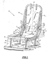
- FIG. 1 The rear end of a motor vehicle is shown partially in Figure 1. This end comprises a floor 11, in which is formed a housing 13. The base of a retractable seat 15 is fixed in this housing 13. Only the The frame of this seat 15 is shown in FIG.
- This seat 15 comprises a seat structure 17 and a back support 19 articulated on this structure 17 by hinge means 21.
- the seat 15 defines a longitudinal direction and a transverse direction relative to a passenger, sitting on the seat.
- the structure 17 comprises two longitudinal members 25 which extend in the longitudinal direction.
- the longitudinal members 25 are interconnected from the front ends by a cross member 27 transverse.
- Each spar 25 comprises a front portion 29 which extends substantially horizontally, and a rear portion 31 which extends in a direction inclined substantially 45 ° to the horizontal, upwards, and provided at the rear of an ear 33.
- the assembly formed by the front portions 29 and the cross member 27 is adapted to support a seat cushion (not shown in Figure 1).
- the structure 17 is connected to the bottom of the housing 13 by means of two deformable articulation quadrilaterals 34, parallel to a median plane of the seat and symmetrical with respect to this plane.
- Each quadrilateral 34 comprises two opposite sides each having a connecting rod 35.
- Each rod 35 is articulated at an upper end 39 to the structure 17, about a transverse axis A-A 'of structure.
- each link 35 is articulated from a lower end 41 at a point of the bottom of the housing 13, about a floor axis B-B 'parallel to the axis A-A'.
- Locking means (not shown) are provided to lock the rotation of each link 35 about the axis B-B ', when activated.
- the support 19 comprises two uprights 51, interconnected by an upper cross member 53 from upper ends.
- a flange 55 of the backrest, intended to support a back cushion (not shown) is fixed to the back of the support 19.
- Each upright 51 extends parallel to a longitudinal axis E-E 'sliding, substantially vertical in Figure 1, between the upper end and a lower end.
- Each upright 51 is respectively connected to a spar 25 at its lower end by the hinge means 21.
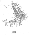
- the articulation means 21 of the support 19 with respect to the structure 17 comprise, for each upright 51, a pivot 71, a longitudinal slide 72 and a slide 73, integral with the pivot 71.
- the assembly formed by the pivot 73 and the slide 72 is rotatably mounted in the lug 33 around a transverse axis F-F 'articulation.
- the support 19 is thus rotatable about the axis FF 'of articulation, relative to the structure 17, between an active projecting position, in which the sliding axis EE' is substantially perpendicular to a horizontal axis and a folded position in which the axis EE 'is substantially parallel to the horizontal axis.
- Locking means 75 can selectively block the rotation of the pivot 71, and consequently the support 19 around the axis of articulation F-F '.
- the slide 72 is formed of a slot of constant width formed along the length of the upright 51.
- the slide 73 comprises a body which extends parallel to the sliding axis E-E 'and which is arranged in the slide 72.
- This body comprises at least one plate resting on an inner side wall of the slide 72.
- the support 19 is thus movable in translation relative to the structure 17, along the axis EE 'of sliding, between a forward position, in which the slide 73 is in the vicinity of a lower point of the slide 72 and a rear position in which the slide 73 is in the vicinity of an upper point of the slide 72.
- blocking means 77 make it possible, selectively, to block the translational movement of the support 19 along the sliding axis E-E '.
- These locking means 77 comprise, for each spar 25, an index 78 rotatably mounted about the axis F-F 'with respect to the structure 17 and a curved notch 79, formed in the associated upright 51 of the support 17.
- the index 78 comprises a pin 81 of cylindrical shape of transverse axis disposed in the notch 79 and carried at the end of a support leg 83.
- the support lug 83 projects out of the ear 33, through a slot 85 formed along a peripheral edge of the lug 33.
- This tab 83 comprises a first end mounted in the ear 33 and a free end projecting out of the slot 85 on which the pin 81 is mounted.
- the slot 85 extends along a peripheral edge of the ear 33 between a lower end 86A and an upper end 86B.
- the lug 83 is rotatably mounted about the hinge axis F-F ', along a peripheral edge of the lug 33, between the upper end 86B and the lower end 86A of the slot 85.
- the notch 79 is formed in the upright 51, between a rear point in the slide 72 in the vicinity of the lower end of the upright 51 and a front point in the upright 51, located at the front of the slide 72.
- the notch 79 is circular in shape, projecting on a median plane of the seat.
- the length of the notch 79 is less than or equal to the length of the slot 85.
- a biasing spring 87 disposed within the lug 33 pushes the support lug 83 and the pin 81 toward the lower end 86A of the slot 85.
- the upper end 86B of the slot is positioned on the ear 33 so that, during a movement of the support 19 around the hinge axis FF 'from its active position to its folded position , the rear point of the notch 79 exceeds this end 86B only from an intermediate release position of the support 19 relative to the structure 17.
- the pin 81 it is impossible to move to its free position since it would abut against the upper end 86B of the slot 85.
- the lower end 86A of the slot 85 is placed so that, during a displacement of the support 19 around the articulation axis FF 'beyond the release position, there is a release position the support 19 in which the pin 81 abuts against the lower end 86A of the slot 85.
- the pin 81 is immobilized relative to the structure 17 against the spring 87 and reaches its free position in the slide 72, when the rear point of the notch 79 is opposite the lower end 86A of the slot 85.
- the sliding axis E-E ' is substantially vertical.
- the support 19 is projecting with respect to the structure 17.
- the pivots 71 are positioned in the vicinity of the lower end of the uprights 51.
- the index 78 In this position, the index 78 is in its locking position, in which the pin 81 bears on the side walls of the notch 79.
- the index finger 78 thus prevents the translation of the support 19 in translation along the length EE axis with respect to the structure 17.
- the operator pivots the support 19 forward around the hinge axis FF 'with respect to the structure 17, via the pivot 71 and the slider 73, as previously described.
- the pin 81 is positioned in the slide 72, in its free position.
- the back support 19 is provided with a headrest, the latter is shifted backwards.
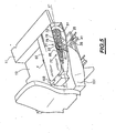
- the operator pivots the support 19 around the pivot 71 to a fully retracted position where the axis EE 'is substantially horizontal and where the slider 73 is positioned in the vicinity of the upper end of the upright 51 (FIG. 4) .
- Figure 5 is a view identical to Figure 4 in which the seat cushions 101 and backrest 103 are shown.
- the relative position of the seat structure 17 and the back support 19 optimizes the relative positioning of the cushions 101 and 103 so that the flange 55 extends substantially horizontally in the extension of the floor 11 of the vehicle .
- the housing 13 is closed and the continuity of the floor 11 of the vehicle is achieved.
- the ratio between the thickness of the cushions 101 and 103 and the height of the seat in the retracted position is optimal in this configuration.
- the displacement of the pin 81 in the notch 79 can be caused when this pin 81 abuts against the lower end 86A of the slot 85, during the pivoting of the support 19 around the axis of articulation EE 'from its active position, without direct action of the seat operator on the pin 81.
- the index 78 is fixedly mounted on the lug 33 of the spar 25 at a determined angular position on the peripheral edge of the lug 33. Furthermore, a return spring is disposed between the pivot 71 and the spar 25 so that the back support 19 is returned to its active position.
- the locking means 21 of the relative translation of the support 19 relative to the structure 17 along the axis of sliding EE ' are released only when the support 19 reaches pivotally about the axis FF' a predetermined angular position relative to the structure 17, in which the pin 81 is positioned in the slide 72.
- This angular position is determined by the position of the index 78 on the spar 25.
- This seat comprises particularly simple and inexpensive hinge means between the seat structure and the file support.
- This seat is also retractable, even when equipped with a headrest and regardless of the position of the headrest.
- this seat In its fully retracted position, this seat can be easily arranged in a housing in the floor of the vehicle, so that the floor has a continuity of appearance.
Description
- La présente invention concerne un siège escamotable, notamment siège de véhicule automobile, du type décrit dans le préambule de la revendication 1.
- Un siège connu du type précité est décrit dans le document FR-A-2 565 908. Il comprend une assise montée sur le plancher du véhicule et un dossier escamotable articulé à cette assise par l'intermédiaire d'une tringlerie complexe. Cette tringlerie permet de déplacer le dossier entre sa position active et une position escamotée par la combinaison d'un mouvement de rotation autour d'un pivot d'articulation transversal par rapport au siège et d'un mouvement simultané de translation relative du dossier par rapport à l'assise.
- De tels sièges ne donnent pas entière satisfaction. En effet, il est nécessaire de replier le siège dans sa position totalement escamotée pour augmenter le volume de chargement du véhicule. Les possibilités d'aménagement intérieur du véhicule sont donc limitées.
- L'invention a pour but de remédier à cet inconvénient, c'est-à-dire de proposer un siège escamotable pour véhicule, qui permette d'augmenter les possibilités d'aménagement intérieur du véhicule.
- A cet effet, l'invention a pour objet un siège escamotable selon la revendication 1.
- Le siège selon l'invention peut comprendre l'une ou plusieurs des caractéristiques des revendications 2 à 8, prise(s) isolément ou suivant toutes combinaisons techniquement possibles.
- L'invention a en outre pour objet un véhicule automobile selon la revendication 9.
- Ce véhicule peut comprendre la caractéristique de la revendication 10.
- L'invention sera mieux comprise à la lecture de la description qui va suivre, donnée uniquement à titre d'exemple et faite en se référant aux dessins annexés, sur lesquels :
- la Figure 1 est une vue en perspective de l'armature d'un siège escamotable selon l'invention, en position active ;
- la Figure 2 est une vue d'un détail de la Figure 1 ;
- la Figure 3 est une vue analogue à la Figure 1, en position de pré-escamotage ;
- la Figure 4 est une vue analogue à la Figure 1, en position escamotée ; et
- la Figure 5 est une vue partielle en perspective de l'aménagement intérieur d'un véhicule selon l'invention.
- Dans tout ce qui suit, les orientations utilisées sont les orientations habituelles d'un véhicule automobile. Ainsi, les termes « avant », « arrière », « droit », « gauche », « inférieur », et « supérieur » s'entendent par rapport à la position d'un conducteur de véhicule automobile et à son sens de marche.
- L'extrémité arrière d'un véhicule automobile est représentée partiellement sur la Figure 1. Cette extrémité comprend un plancher 11, dans lequel est ménagé un logement 13. La base d'un siège 15 escamotable est fixée dans ce logement 13. Seule l'armature de ce siège 15 est représentée sur la Figure 1.
- Ce siège 15 comprend une structure d'assise 17 et un support de dossier 19, articulé sur cette structure 17 par des moyens d'articulation 21.
- Le siège 15 définit une direction longitudinale et une direction transversale par rapport à un passager, assis sur le siège.
- La structure 17 comprend deux longerons 25 qui s'étendent suivant la direction longitudinale. Les longerons 25 sont reliés entre eux depuis des extrémités avant, par une traverse 27 transversale.
- Chaque longeron 25 comprend une portion avant 29 qui s'étend sensiblement horizontalement, et une portion arrière 31 qui s'étend suivant une direction inclinée sensiblement de 45° par rapport à l'horizontale, vers le haut, et munie à l'arrière d'une oreille 33.
- L'ensemble formé par les portions avant 29 et la traverse 27 est adapté pour soutenir un coussin d'assise (non représenté sur la Figure 1).
- Par ailleurs, la structure 17 est reliée au fond du logement 13 par l'intermédiaire de deux quadrilatères d'articulation 34 déformables, parallèles à un plan médian du siège et symétriques par rapport à ce plan.
- Chaque quadrilatère 34 comprend deux cotés opposés comportant chacun une bielle 35.
- Chaque bielle 35 est articulée en une extrémité supérieure 39 à la structure 17, autour d'un axe transversal A-A' de structure.
- De même, chaque bielle 35 est articulée depuis une extrémité inférieure 41 en un point du fond du logement 13, autour d'un axe B-B' de plancher parallèle à l'axe A-A'.
- Des moyens de verrouillage (non représentés) sont prévus pour bloquer la rotation de chaque bielle 35 autour de l'axe B-B', lorsqu'ils sont activés.
- Le support 19 comprend deux montants 51, reliés entre eux par une traverse supérieure 53 depuis des extrémités supérieures. Un flasque 55 de fond de dossier, destiné à supporter un coussin de dossier (non représenté) est fixé à l'arrière du support 19.
- Chaque montant 51 s'étend parallèlement à un axe E-E' longitudinal de coulissement, sensiblement vertical sur la Figure 1, entre l'extrémité supérieure et une extrémité inférieure. Chaque montant 51 est relié respectivement à un longeron 25 au niveau de son extrémité inférieure, par les moyens d'articulation 21.
- Comme illustré sur la Figure 2, les moyens d'articulation 21 du support 19 par rapport à la structure 17 comprennent, pour chaque montant 51, un pivot 71, une coulisse longitudinale 72 et un coulisseau 73, solidaire du pivot 71.
- L'ensemble formé par le pivot 73 et le coulisseau 72 est monté rotatif dans l'oreille 33 autour d'un axe F-F' transversal d'articulation. Le support 19 est ainsi mobile en rotation autour de l'axe F-F' d'articulation, par rapport à la structure 17, entre une position active en saillie, dans laquelle l'axe de coulissement E-E' est sensiblement perpendiculaire à un axe horizontal et une position repliée dans laquelle l'axe E-E' est sensiblement parallèle à l'axe horizontal.
- Des moyens de verrouillage 75 permettent de bloquer, de manière sélective, la rotation du pivot 71, et par suite du support 19 autour de l'axe d'articulation F-F'.
- La coulisse 72 est formée d'une fente de largeur constante ménagée suivant la longueur du montant 51.
- Le coulisseau 73 comporte un corps qui s'étend parallèlement à l'axe de coulissement E-E', et qui est disposé dans la coulisse 72. Ce corps comprend au moins un plat en appui sur une paroi latérale interne de la coulisse 72.
- Le support 19 est ainsi mobile en translation par rapport à la structure 17, le long de l'axe E-E' de coulissement, entre une position avant, dans laquelle le coulisseau 73 est au voisinage d'un point inférieur de la coulisse 72 et une position arrière dans laquelle le coulisseau 73 est au voisinage d'un point supérieur de la coulisse 72.
- Par ailleurs, des moyens de blocage 77 permettent de bloquer, de manière sélective, le mouvement de translation du support 19 le long de l'axe de coulissement E-E'.
- Ces moyens de blocage 77 comprennent, pour chaque longeron 25, un index 78 monté rotatif autour de l'axe F-F' par rapport à la structure 17 et une encoche courbe 79, ménagée dans le montant 51 associé du support 17.
- L'index 78 comprend une goupille 81 de forme cylindrique d'axe transversal disposée dans l'encoche 79 et portée à l'extrémité d'une patte de support 83.
- La patte de support 83 fait saillie hors de l'oreille 33, à travers une fente 85 ménagée suivant un bord périphérique de l'oreille 33.
- Cette patte 83 comprend une première extrémité montée dans l'oreille 33 et une extrémité libre en saillie hors de la fente 85, sur laquelle est montée la goupille 81.
- La fente 85 s'étend suivant un bord périphérique de l'oreille 33 entre une extrémité inférieure 86A et une extrémité supérieure 86B.
- Par ailleurs, la patte 83 est monté rotative autour de l'axe d'articulation F-F', le long d'un bord périphérique de l'oreille 33, entre l'extrémité supérieure 86B et l'extrémité inférieure 86A de la fente 85.
- L'encoche 79 est ménagée dans le montant 51, entre un point arrière dans la coulisse 72 au voisinage de l'extrémité inférieure du montant 51 et un point avant dans le montant 51, situé à l'avant de la coulisse 72.
- L'encoche 79 est de forme circulaire, en projection sur un plan médian du siège.
- La longueur de l'encoche 79 est inférieure ou égale à la longueur de la fente 85. Ainsi, lorsque la fente 85 et l'encoche 79 sont placées en regard l'une de l'autre, lors de la rotation du support 19 par rapport à la structure 17 autour de l'axe d'articulation F-F', la goupille 81 peut être coulissée librement dans l'encoche 79 jusqu'à la coulisse 72, entre une position de blocage dans l'encoche 79 et une position libre dans la coulisse 72.
- Un ressort 87 de mise en contrainte, disposé à l'intérieur de l'oreille 33 pousse la patte de support 83 et la goupille 81 vers l'extrémité inférieure 86A de la fente 85.
- Par ailleurs, l'extrémité supérieure 86B de la fente est positionnée sur l'oreille 33 de sorte que, lors d'un déplacement du support 19 autour de l'axe d'articulation F-F' depuis sa position active jusqu'à sa position repliée, le point arrière de l'encoche 79 dépasse cette extrémité 86B uniquement à partir d'une position intermédiaire de libération du support 19 par rapport à la structure 17. Ainsi, entre la position active et cette position de libération, il est impossible de déplacer la goupille 81 jusqu'à sa position libre puisque celle-ci viendrait buter contre l'extrémité supérieure 86B de la fente 85.
- De même, l'extrémité inférieure 86A de la fente 85 est placée de sorte que, lors d'un déplacement du support 19 autour de l'axe d'articulation F-F' au delà de la position de libération, il existe une position de déblocage du support 19 dans laquelle la goupille 81 bute contre l'extrémité inférieure 86A de la fente 85. Ainsi, lors d'un déplacement ultérieur du support 19 par rapport à la structure 17 vers la position repliée, la goupille 81 est immobilisée par rapport à la structure 17 à l'encontre du ressort 87 et atteint sa position libre dans la coulisse 72, lorsque le point arrière de l'encoche 79 est en regard de l'extrémité inférieure 86A de la fente 85.
- Dans ce cas, lorsque la goupille 81 atteint sa position libre, le support 19 est dans sa position repliée.
- On décrira maintenant comme exemple le fonctionnement du siège escamotable 15 depuis sa position active (Figure 1) jusqu'à une position partiellement escamotée, puis depuis sa position active jusqu'à une position totalement escamotée (Figure 4). Ces différentes positions seront décrites en détail ci-dessous.
- Initialement, et comme représenté sur la Figure 1, le support de dossier 19 est dans sa position active.
- Dans cette position et comme précisé plus haut, l'axe de coulissement E-E' est sensiblement vertical. Le support 19 est en saillie par rapport à la structure 17. Par ailleurs, les pivots 71 sont positionnés au voisinage de l'extrémité inférieure des montants 51.
- Lorsque le volume de chargement à l'arrière du siège 15 doit être légèrement augmenté, un opérateur libère les moyens de verrouillage 75 du support 19 sur la structure 17. Il pivote ensuite le support 19 d'environ 30° vers l'avant, autour de l'axe d'articulation F-F', par rapport à la structure 17 via le pivot 71 et le coulisseau 73. Le support 19 se trouve alors dans une position partiellement escamotée.
- Dans cette position, l'index 78 est dans sa position de blocage, dans laquelle la goupille 81 est en appui sur les parois latérales de l'encoche 79. L'index 78 empêche ainsi le déplacement du support 19 en translation le long de l'axe E-E' par rapport à la structure 17.
- Lorsque le volume de chargement doit être augmenté de manière significative à partir de la position active, l'opérateur pivote le support 19 vers l'avant autour de l'axe d'articulation F-F' par rapport à la structure 17, via le pivot 71 et le coulisseau 73, comme décrit précédemment.
- Lorsque le point arrière de l'encoche 79 dépasse l'extrémité supérieure 86B de la fente 85, l'opérateur déplace la goupille 81 vers l'arrière le long de l'encoche 79 jusqu'à la coulisse 72. Lors de ce déplacement, la force de rappel élastique exercée par le ressort 87 sur la patte 83 est surmontée.
- Ainsi, et comme représenté sur la Figure 3, la goupille 81 est positionnée dans la coulisse 72, dans sa position libre.
- L'opérateur déplace alors le support 19 en translation par rapport à la structure 17, le long de l'axe E-E' de coulissement, vers l'arrière.
- Si le support de dossier 19 est muni d'un appui-tête, ce dernier est décalé vers l'arrière.
- Simultanément, l'opérateur pivote le support 19 autour du pivot 71 jusqu'à une position totalement escamotée où l'axe E-E' est sensiblement horizontal et où le coulisseau 73 est positionné au voisinage de l'extrémité supérieure du montant 51 (Figure 4).
- Enfin, il libère les moyens de blocage (non représentés) des bielles d'articulation 35 de la structure 17. Il pivote la structure 17 vers l'avant, autour des axes de structure et de plancher A-A' et B-B', par l'intermédiaire des bielles 35, jusqu'à ce que la structure 17 repose sensiblement sur le fond du logement 13 (Figure 4). Dans cette position, l'axe de coulissement E-E' est légèrement incliné par rapport à l'horizontale et le support 19 est décalé vers l'arrière par rapport à la structure 17.
- La Figure 5 est une vue identique à la Figure 4 dans laquelle les coussins d'assise 101 et de dossier 103 sont représentés. Comme illustré sur cette Figure, la position relative de la structure d'assise 17 et du support de dossier 19 optimise le positionnement relatif des coussins 101 et 103 de sorte que le flasque 55 s'étend sensiblement horizontalement dans le prolongement du plancher 11 du véhicule. Ainsi, dans la position escamotée du support 19, le logement 13 est obturé et la continuité du plancher 11 du véhicule est réalisée. Par ailleurs, le rapport entre l'épaisseur des coussins 101 et 103 et la hauteur du siège en position escamotée est optimal dans cette configuration.
- Dans une première variante, le déplacement de la goupille 81 dans l'encoche 79 peut être provoqué lorsque cette goupille 81 bute contre l'extrémité inférieure 86A de la fente 85, lors du pivotement du support 19 autour de l'axe d'articulation E-E' depuis sa position active, sans action directe de l'opérateur du siège sur la goupille 81.
- Dans une deuxième variante, l'index 78 est monté fixe sur l'oreille 33 du longeron 25 en une position angulaire déterminée sur le bord périphérique de l'oreille 33. Par ailleurs, un ressort de rappel est disposé entre le pivot 71 et le longeron 25 de sorte que le support de dossier 19 est rappelé dans sa position active.
- A la différence du premier siège selon l'invention, les moyens de blocage 21 de la translation relative du support 19 par rapport à la structure 17 le long de l'axe de coulissement E-E' sont libérés uniquement lorsque le support 19 atteint par pivotement autour de l'axe F-F' une position angulaire prédéterminée par rapport à la structure 17, dans laquelle la goupille 81 est positionnée dans la coulisse 72. Cette position angulaire est déterminée par la position du index 78 sur le longeron 25.
- Grâce à l'invention qui vient d'être décrite, il est possible de disposer d'un siège escamotable, qui augmente les possibilités d'aménagement intérieur d'un véhicule automobile. En effet, ce siège peut être escamoté partiellement ou totalement selon les besoins de l'utilisateur du véhicule.
- Ce siège comprend des moyens d'articulation particulièrement simples et peu coûteux entre la structure d'assise et le support de dossier.
- Ce siège est par ailleurs escamotable, même lorsqu'il est muni d'un appui-tête et quelle que soit la position de cet appui-tête.
- Dans sa position totalement escamotée, ce siège peut être facilement disposé dans un logement ménagé dans le plancher du véhicule, de sorte que le plancher présente une continuité d'aspect.
Claims (10)
- Siège (15) escamotable, notamment siège de véhicule automobile, du type comprenant :- une structure (17) d'assise;- un support (19) de dossier, articulé sur la structure (17), autour d'un axe (F-F') d'articulation sensiblement transversal par rapport au siège (15), lequel support (19) est en outre monté mobile en translation par rapport à ladite structure (17) le long d'un axe (E-E') de coulissement, sensiblement perpendiculaire à l'axe d'articulation (F-F'), le support (19) étant mobile entre une position active en saillie par rapport à ladite structure (17) et une position escamotée ;caractérisé en ce que les mouvements de translation et de rotation du support (19) par rapport à la structure (17) sont indépendants, et en ce qu'il comprend en outre des moyens indépendants (75 ; 77) de blocage respectivement en translation et en rotation de chacun desdits mouvements du support (19) par rapport à ladite structure (17).
- Siège (15) selon la revendication 1, caractérisé en ce qu'il comprend des moyens d'articulation (21) entre la structure (17) et le support (19), ces moyens d'articulation (21) comprenant :- une coulisse (72), ménagée dans le support (19) et s'étendant sensiblement parallèlement à l'axe de coulissement (E-E') ;- un coulisseau (73), monté rotatif sur la structure (17) autour de l'axe d'articulation (F-F') et monté coulissant dans la coulisse (72) ;et en ce que les moyens de blocage (77) du mouvement de translation relative du support (19) par rapport à la structure (17) le long de l'axe de coulissement (E-E') comportent :- une encoche (79) ménagée dans le support (19) et débouchant latéralement dans ladite coulisse (72) par rapport audit deuxième axe (E-E') ; et- un organe de blocage (78), monté sur la structure (17) et mobile par rapport au support (19) entre au moins une position de blocage dans l'encoche (79) et une position libre dans la coulisse (72).
- Siège (15) selon la revendication 2, caractérisé en ce que l'organe de blocage (78) est monté mobile sur la structure (17), et en ce que les moyens de blocage (77) du mouvement de translation relative du support (19) par rapport à la structure (17) le long de l'axe de coulissement (E-E') comprennent en outre des moyens de rappel (87) de l'organe de blocage (78) dans sa position de blocage.
- Siège (15) selon la revendication 3, caractérisé en ce que la structure (17) comporte une butée d'arrêt (86B) de l'organe de blocage (78) suivant sa course de déplacement dans l'encoche (79) vers sa position libre pour au moins une position intermédiaire du support (19) par rapport à la structure (17), pour empêcher l'organe de blocage (78) d'atteindre sa position libre.
- Siège (15) selon l'une des revendications 3 ou 4, caractérisé en ce que la structure (17) comprend en outre une butée d'immobilisation (86A) de l'organe, de blocage (78), pour immobiliser l'organe de blocage (78) par rapport à la structure (17) à l'encontre de l'action des moyens de rappel (87), le support (19) restant mobile en rotation par rapport à la structure (17) au-delà de la position de libération jusqu'à ce que l'organe de blocage (78) atteigne sa position libre.
- Siège (15) selon la revendication 2, caractérisé en ce que l'organe de blocage (78) est monté fixe sur ladite structure (17).
- Siège (15) selon la revendication 6, caractérisé en ce que les moyens d'articulation (21) entre ladite structure (17) et ledit support (19) comprennent en outre des moyens de rappel du support (19) dans ladite position active.
- Siège (15) selon l'une quelconque des revendications précédentes, caractérisé en ce que le support (19) s'étend longitudinalement le long d'un axe de support, l'axe de coulissement (E-E') et l'axe de support étant sensiblement parallèles.
- Véhicule automobile, caractérisé en ce qu'il comprend au moins un siège (15) selon l'une quelconque des revendications précédentes
- Véhicule selon la revendication 9, caractérisé en ce qu'il comprend en outre un plancher (11) et au moins une bielle (35) articulée en une première extrémité (39) à un point de la structure (17), autour d'un axe (A-A') de structure, sensiblement transversal par rapport à une direction longitudinale du véhicule, ladite bielle (35) étant articulée en une deuxième extrémité (41) à un point du plancher (13), autour d'un axe de plancher (B-B') parallèle audit axe (A-A') de structure.
Applications Claiming Priority (2)
| Application Number | Priority Date | Filing Date | Title |
|---|---|---|---|
| FR0313064 | 2003-11-06 | ||
| FR0313064A FR2862029B1 (fr) | 2003-11-06 | 2003-11-06 | Siege escamotable, notamment sige de vehicule automobile et vehicule automobile correspondant |
Publications (2)
| Publication Number | Publication Date |
|---|---|
| EP1529681A1 EP1529681A1 (fr) | 2005-05-11 |
| EP1529681B1 true EP1529681B1 (fr) | 2006-10-25 |
Family
ID=34429952
Family Applications (1)
| Application Number | Title | Priority Date | Filing Date |
|---|---|---|---|
| EP04292541A Not-in-force EP1529681B1 (fr) | 2003-11-06 | 2004-10-26 | Siège escamotable, notamment siège de véhicule automobile et véhicule automobile correspondant |
Country Status (5)
| Country | Link |
|---|---|
| EP (1) | EP1529681B1 (fr) |
| AT (1) | ATE343492T1 (fr) |
| DE (1) | DE602004002914T2 (fr) |
| ES (1) | ES2274398T3 (fr) |
| FR (1) | FR2862029B1 (fr) |
Families Citing this family (5)
| Publication number | Priority date | Publication date | Assignee | Title |
|---|---|---|---|---|
| DE102006058482A1 (de) | 2006-12-12 | 2008-07-10 | GM Global Technology Operations, Inc., Detroit | Verschwenkbarer Kraftfahrzeugsitz und Kraftfahrzeug mit einem solchen Kraftfahrzeugsitz |
| DE102007053958B4 (de) * | 2007-02-26 | 2016-04-28 | Johnson Controls Gmbh | Fahrzeugsitz |
| DE102007055082B4 (de) | 2007-02-26 | 2011-06-16 | Johnson Controls Gmbh | Fahrzeugsitz |
| DE102011016649A1 (de) * | 2011-04-09 | 2012-10-11 | GM Global Technology Operations LLC (n. d. Gesetzen des Staates Delaware) | Fahrzeugsutz und Kraftfahrzeug mit einem solchen Fahrzeugsitz |
| US10696198B2 (en) * | 2018-07-19 | 2020-06-30 | Ford Global Technologies, Llc | AV and transport scissor jack rear seat system |
Family Cites Families (5)
| Publication number | Priority date | Publication date | Assignee | Title |
|---|---|---|---|---|
| DE3507894C2 (de) * | 1984-03-21 | 1986-11-06 | Daimler-Benz Ag, 7000 Stuttgart | Kraftwagensitz mit einer aus der Gebrauchslage nach vorn klappbaren Rückenlehne |
| JP3136964B2 (ja) * | 1995-09-22 | 2001-02-19 | トヨタ自動車株式会社 | 車両用リヤシート装置 |
| JP3926485B2 (ja) * | 1998-07-27 | 2007-06-06 | ジョンソン コントロールズ オートモーティブ システムズ株式会社 | 自動車のフラット化シート構造 |
| US6070934A (en) * | 1999-02-01 | 2000-06-06 | Ford Motor Company | Folding seat mounting apparatus |
| JP3976240B2 (ja) * | 2002-03-06 | 2007-09-12 | トヨタ紡織株式会社 | 車両用シート |
-
2003
- 2003-11-06 FR FR0313064A patent/FR2862029B1/fr not_active Expired - Fee Related
-
2004
- 2004-10-26 AT AT04292541T patent/ATE343492T1/de not_active IP Right Cessation
- 2004-10-26 ES ES04292541T patent/ES2274398T3/es active Active
- 2004-10-26 EP EP04292541A patent/EP1529681B1/fr not_active Not-in-force
- 2004-10-26 DE DE602004002914T patent/DE602004002914T2/de not_active Expired - Fee Related
Also Published As
| Publication number | Publication date |
|---|---|
| DE602004002914T2 (de) | 2007-04-12 |
| ATE343492T1 (de) | 2006-11-15 |
| FR2862029A1 (fr) | 2005-05-13 |
| DE602004002914D1 (de) | 2006-12-07 |
| EP1529681A1 (fr) | 2005-05-11 |
| FR2862029B1 (fr) | 2006-02-17 |
| ES2274398T3 (es) | 2007-05-16 |
Similar Documents
| Publication | Publication Date | Title |
|---|---|---|
| FR2851211A1 (fr) | Siege rabattable et vehicule comportant un tel siege | |
| FR2795688A1 (fr) | Siege de vehicule equipe d'un mecanisme d'articulation | |
| FR2877283A1 (fr) | Siege escamotable dans le plancher | |
| FR2734766A1 (fr) | Siege d'automobile a surface d'assise reglable | |
| FR2780351A1 (fr) | Siege de vehicule a ancrage avant automatique, et vehicule comportant un tel siege | |
| FR2910401A1 (fr) | Appui-tete escamotable | |
| FR2820696A1 (fr) | Siege de vehicule dote d'un dossier rabattable | |
| FR2806047A1 (fr) | Mecanisme de verrouillage de siege | |
| FR2929179A1 (fr) | Siege de vehicule automobile et vehicule muni d'un tel siege. | |
| WO2010010274A1 (fr) | Siege de vehicule | |
| FR2838391A1 (fr) | Dispositif de fixation d'un siege sur un plancher de vehicule et siege equipe d'un tel dispositif de fixation | |
| EP1529681B1 (fr) | Siège escamotable, notamment siège de véhicule automobile et véhicule automobile correspondant | |
| FR2910406A1 (fr) | Appui-tete escamotable | |
| EP0373081B1 (fr) | Siège escamotable notamment pour équipement de véhicules automobiles | |
| FR2904585A1 (fr) | Siege d'automobile comportant un appui-tete repliable contre le dossier. | |
| WO2010001052A2 (fr) | Siege de vehicule automobile et vehicule automobile muni d'un tel siege | |
| EP1449712B1 (fr) | Siège pliable pour véhicule automobile et véhicule automobile correspondant | |
| FR2877280A1 (fr) | Siege pour vehicule automobile mobile selon un premier axe x et un second axe y et vehicule automobile comprenant un tel siege | |
| FR2860460A1 (fr) | Siege escamotable de vehicule automobile, notamment arriere | |
| FR2914880A1 (fr) | Siege arriere pour vehicule automobile. | |
| FR2892349A1 (fr) | Siege de vehicule automobile et vehicule automobile muni d'un tel siege | |
| FR2942432A1 (fr) | Agencement de siege repliable ou escamotable de vehicule automobile | |
| FR3071201B1 (fr) | Accoudoir de pilier central | |
| FR2868740A1 (fr) | Dispositif de fixation d'un siege sur un plancher de vehicule, siege equipe d'un tel dispositif de fixation et vehicule comprenant un tel siege | |
| FR2850914A1 (fr) | Siege de vehicule comportant un dossier rabattable vers l'avant |
Legal Events
| Date | Code | Title | Description |
|---|---|---|---|
| PUAI | Public reference made under article 153(3) epc to a published international application that has entered the european phase |
Free format text: ORIGINAL CODE: 0009012 |
|
| AK | Designated contracting states |
Kind code of ref document: A1 Designated state(s): AT BE BG CH CY CZ DE DK EE ES FI FR GB GR HU IE IT LI LU MC NL PL PT RO SE SI SK TR |
|
| AX | Request for extension of the european patent |
Extension state: AL HR LT LV MK |
|
| 17P | Request for examination filed |
Effective date: 20051020 |
|
| AKX | Designation fees paid |
Designated state(s): AT BE BG CH CY CZ DE DK EE ES FI FR GB GR HU IE IT LI LU MC NL PL PT RO SE SI SK TR |
|
| GRAP | Despatch of communication of intention to grant a patent |
Free format text: ORIGINAL CODE: EPIDOSNIGR1 |
|
| GRAS | Grant fee paid |
Free format text: ORIGINAL CODE: EPIDOSNIGR3 |
|
| GRAA | (expected) grant |
Free format text: ORIGINAL CODE: 0009210 |
|
| AK | Designated contracting states |
Kind code of ref document: B1 Designated state(s): AT BE BG CH CY CZ DE DK EE ES FI FR GB GR HU IE IT LI LU MC NL PL PT RO SE SI SK TR |
|
| PG25 | Lapsed in a contracting state [announced via postgrant information from national office to epo] |
Ref country code: IT Free format text: LAPSE BECAUSE OF FAILURE TO SUBMIT A TRANSLATION OF THE DESCRIPTION OR TO PAY THE FEE WITHIN THE PRESCRIBED TIME-LIMIT;WARNING: LAPSES OF ITALIAN PATENTS WITH EFFECTIVE DATE BEFORE 2007 MAY HAVE OCCURRED AT ANY TIME BEFORE 2007. THE CORRECT EFFECTIVE DATE MAY BE DIFFERENT FROM THE ONE RECORDED. Effective date: 20061025 Ref country code: RO Free format text: LAPSE BECAUSE OF FAILURE TO SUBMIT A TRANSLATION OF THE DESCRIPTION OR TO PAY THE FEE WITHIN THE PRESCRIBED TIME-LIMIT Effective date: 20061025 Ref country code: NL Free format text: LAPSE BECAUSE OF FAILURE TO SUBMIT A TRANSLATION OF THE DESCRIPTION OR TO PAY THE FEE WITHIN THE PRESCRIBED TIME-LIMIT Effective date: 20061025 Ref country code: SI Free format text: LAPSE BECAUSE OF FAILURE TO SUBMIT A TRANSLATION OF THE DESCRIPTION OR TO PAY THE FEE WITHIN THE PRESCRIBED TIME-LIMIT Effective date: 20061025 Ref country code: SK Free format text: LAPSE BECAUSE OF FAILURE TO SUBMIT A TRANSLATION OF THE DESCRIPTION OR TO PAY THE FEE WITHIN THE PRESCRIBED TIME-LIMIT Effective date: 20061025 Ref country code: PL Free format text: LAPSE BECAUSE OF FAILURE TO SUBMIT A TRANSLATION OF THE DESCRIPTION OR TO PAY THE FEE WITHIN THE PRESCRIBED TIME-LIMIT Effective date: 20061025 Ref country code: FI Free format text: LAPSE BECAUSE OF FAILURE TO SUBMIT A TRANSLATION OF THE DESCRIPTION OR TO PAY THE FEE WITHIN THE PRESCRIBED TIME-LIMIT Effective date: 20061025 Ref country code: CZ Free format text: LAPSE BECAUSE OF FAILURE TO SUBMIT A TRANSLATION OF THE DESCRIPTION OR TO PAY THE FEE WITHIN THE PRESCRIBED TIME-LIMIT Effective date: 20061025 Ref country code: IE Free format text: LAPSE BECAUSE OF FAILURE TO SUBMIT A TRANSLATION OF THE DESCRIPTION OR TO PAY THE FEE WITHIN THE PRESCRIBED TIME-LIMIT Effective date: 20061025 Ref country code: AT Free format text: LAPSE BECAUSE OF FAILURE TO SUBMIT A TRANSLATION OF THE DESCRIPTION OR TO PAY THE FEE WITHIN THE PRESCRIBED TIME-LIMIT Effective date: 20061025 |
|
| REG | Reference to a national code |
Ref country code: GB Ref legal event code: FG4D Free format text: NOT ENGLISH |
|
| PG25 | Lapsed in a contracting state [announced via postgrant information from national office to epo] |
Ref country code: MC Free format text: LAPSE BECAUSE OF NON-PAYMENT OF DUE FEES Effective date: 20061031 |
|
| REG | Reference to a national code |
Ref country code: CH Ref legal event code: EP |
|
| GBT | Gb: translation of ep patent filed (gb section 77(6)(a)/1977) |
Effective date: 20061108 |
|
| REG | Reference to a national code |
Ref country code: IE Ref legal event code: FG4D Free format text: LANGUAGE OF EP DOCUMENT: FRENCH |
|
| REF | Corresponds to: |
Ref document number: 602004002914 Country of ref document: DE Date of ref document: 20061207 Kind code of ref document: P |
|
| PG25 | Lapsed in a contracting state [announced via postgrant information from national office to epo] |
Ref country code: BG Free format text: LAPSE BECAUSE OF FAILURE TO SUBMIT A TRANSLATION OF THE DESCRIPTION OR TO PAY THE FEE WITHIN THE PRESCRIBED TIME-LIMIT Effective date: 20070125 Ref country code: DK Free format text: LAPSE BECAUSE OF FAILURE TO SUBMIT A TRANSLATION OF THE DESCRIPTION OR TO PAY THE FEE WITHIN THE PRESCRIBED TIME-LIMIT Effective date: 20070125 Ref country code: SE Free format text: LAPSE BECAUSE OF FAILURE TO SUBMIT A TRANSLATION OF THE DESCRIPTION OR TO PAY THE FEE WITHIN THE PRESCRIBED TIME-LIMIT Effective date: 20070125 |
|
| PG25 | Lapsed in a contracting state [announced via postgrant information from national office to epo] |
Ref country code: PT Free format text: LAPSE BECAUSE OF FAILURE TO SUBMIT A TRANSLATION OF THE DESCRIPTION OR TO PAY THE FEE WITHIN THE PRESCRIBED TIME-LIMIT Effective date: 20070326 |
|
| NLV1 | Nl: lapsed or annulled due to failure to fulfill the requirements of art. 29p and 29m of the patents act | ||
| REG | Reference to a national code |
Ref country code: ES Ref legal event code: FG2A Ref document number: 2274398 Country of ref document: ES Kind code of ref document: T3 |
|
| REG | Reference to a national code |
Ref country code: IE Ref legal event code: FD4D |
|
| PLBE | No opposition filed within time limit |
Free format text: ORIGINAL CODE: 0009261 |
|
| STAA | Information on the status of an ep patent application or granted ep patent |
Free format text: STATUS: NO OPPOSITION FILED WITHIN TIME LIMIT |
|
| 26N | No opposition filed |
Effective date: 20070726 |
|
| BERE | Be: lapsed |
Owner name: PEUGEOT CITROEN AUTOMOBILES S.A. Effective date: 20061031 |
|
| PG25 | Lapsed in a contracting state [announced via postgrant information from national office to epo] |
Ref country code: GR Free format text: LAPSE BECAUSE OF FAILURE TO SUBMIT A TRANSLATION OF THE DESCRIPTION OR TO PAY THE FEE WITHIN THE PRESCRIBED TIME-LIMIT Effective date: 20070126 |
|
| PG25 | Lapsed in a contracting state [announced via postgrant information from national office to epo] |
Ref country code: EE Free format text: LAPSE BECAUSE OF FAILURE TO SUBMIT A TRANSLATION OF THE DESCRIPTION OR TO PAY THE FEE WITHIN THE PRESCRIBED TIME-LIMIT Effective date: 20061025 |
|
| PG25 | Lapsed in a contracting state [announced via postgrant information from national office to epo] |
Ref country code: LU Free format text: LAPSE BECAUSE OF NON-PAYMENT OF DUE FEES Effective date: 20061026 Ref country code: TR Free format text: LAPSE BECAUSE OF FAILURE TO SUBMIT A TRANSLATION OF THE DESCRIPTION OR TO PAY THE FEE WITHIN THE PRESCRIBED TIME-LIMIT Effective date: 20061025 Ref country code: HU Free format text: LAPSE BECAUSE OF FAILURE TO SUBMIT A TRANSLATION OF THE DESCRIPTION OR TO PAY THE FEE WITHIN THE PRESCRIBED TIME-LIMIT Effective date: 20070426 |
|
| PG25 | Lapsed in a contracting state [announced via postgrant information from national office to epo] |
Ref country code: CY Free format text: LAPSE BECAUSE OF FAILURE TO SUBMIT A TRANSLATION OF THE DESCRIPTION OR TO PAY THE FEE WITHIN THE PRESCRIBED TIME-LIMIT Effective date: 20061025 |
|
| PGFP | Annual fee paid to national office [announced via postgrant information from national office to epo] |
Ref country code: DE Payment date: 20081030 Year of fee payment: 5 |
|
| PGFP | Annual fee paid to national office [announced via postgrant information from national office to epo] |
Ref country code: FR Payment date: 20081028 Year of fee payment: 5 |
|
| REG | Reference to a national code |
Ref country code: CH Ref legal event code: PL |
|
| PG25 | Lapsed in a contracting state [announced via postgrant information from national office to epo] |
Ref country code: BE Free format text: LAPSE BECAUSE OF FAILURE TO SUBMIT A TRANSLATION OF THE DESCRIPTION OR TO PAY THE FEE WITHIN THE PRESCRIBED TIME-LIMIT Effective date: 20061031 |
|
| PG25 | Lapsed in a contracting state [announced via postgrant information from national office to epo] |
Ref country code: LI Free format text: LAPSE BECAUSE OF NON-PAYMENT OF DUE FEES Effective date: 20081031 Ref country code: CH Free format text: LAPSE BECAUSE OF NON-PAYMENT OF DUE FEES Effective date: 20081031 |
|
| PGFP | Annual fee paid to national office [announced via postgrant information from national office to epo] |
Ref country code: GB Payment date: 20090928 Year of fee payment: 6 |
|
| PGFP | Annual fee paid to national office [announced via postgrant information from national office to epo] |
Ref country code: ES Payment date: 20091006 Year of fee payment: 6 |
|
| PGFP | Annual fee paid to national office [announced via postgrant information from national office to epo] |
Ref country code: IT Payment date: 20091008 Year of fee payment: 6 |
|
| REG | Reference to a national code |
Ref country code: FR Ref legal event code: ST Effective date: 20100630 |
|
| PG25 | Lapsed in a contracting state [announced via postgrant information from national office to epo] |
Ref country code: FR Free format text: LAPSE BECAUSE OF NON-PAYMENT OF DUE FEES Effective date: 20091102 Ref country code: DE Free format text: LAPSE BECAUSE OF NON-PAYMENT OF DUE FEES Effective date: 20100501 |
|
| GBPC | Gb: european patent ceased through non-payment of renewal fee |
Effective date: 20101026 |
|
| PG25 | Lapsed in a contracting state [announced via postgrant information from national office to epo] |
Ref country code: GB Free format text: LAPSE BECAUSE OF NON-PAYMENT OF DUE FEES Effective date: 20101026 |
|
| REG | Reference to a national code |
Ref country code: ES Ref legal event code: FD2A Effective date: 20111118 |
|
| PG25 | Lapsed in a contracting state [announced via postgrant information from national office to epo] |
Ref country code: IT Free format text: LAPSE BECAUSE OF NON-PAYMENT OF DUE FEES Effective date: 20101026 |
|
| PG25 | Lapsed in a contracting state [announced via postgrant information from national office to epo] |
Ref country code: ES Free format text: LAPSE BECAUSE OF NON-PAYMENT OF DUE FEES Effective date: 20101027 |