EP1529544B1 - Hämatokritsensor - Google Patents
Hämatokritsensor Download PDFInfo
- Publication number
- EP1529544B1 EP1529544B1 EP03765272A EP03765272A EP1529544B1 EP 1529544 B1 EP1529544 B1 EP 1529544B1 EP 03765272 A EP03765272 A EP 03765272A EP 03765272 A EP03765272 A EP 03765272A EP 1529544 B1 EP1529544 B1 EP 1529544B1
- Authority
- EP
- European Patent Office
- Prior art keywords
- blood
- hematocrit
- blood circuit
- light
- housing
- Prior art date
- Legal status (The legal status is an assumption and is not a legal conclusion. Google has not performed a legal analysis and makes no representation as to the accuracy of the status listed.)
- Expired - Lifetime
Links
Images








Classifications
-
- A—HUMAN NECESSITIES
- A61—MEDICAL OR VETERINARY SCIENCE; HYGIENE
- A61M—DEVICES FOR INTRODUCING MEDIA INTO, OR ONTO, THE BODY; DEVICES FOR TRANSDUCING BODY MEDIA OR FOR TAKING MEDIA FROM THE BODY; DEVICES FOR PRODUCING OR ENDING SLEEP OR STUPOR
- A61M1/00—Suction or pumping devices for medical purposes; Devices for carrying-off, for treatment of, or for carrying-over, body-liquids; Drainage systems
- A61M1/14—Dialysis systems; Artificial kidneys; Blood oxygenators ; Reciprocating systems for treatment of body fluids, e.g. single needle systems for hemofiltration or pheresis
- A61M1/16—Dialysis systems; Artificial kidneys; Blood oxygenators ; Reciprocating systems for treatment of body fluids, e.g. single needle systems for hemofiltration or pheresis with membranes
-
- A—HUMAN NECESSITIES
- A61—MEDICAL OR VETERINARY SCIENCE; HYGIENE
- A61M—DEVICES FOR INTRODUCING MEDIA INTO, OR ONTO, THE BODY; DEVICES FOR TRANSDUCING BODY MEDIA OR FOR TAKING MEDIA FROM THE BODY; DEVICES FOR PRODUCING OR ENDING SLEEP OR STUPOR
- A61M1/00—Suction or pumping devices for medical purposes; Devices for carrying-off, for treatment of, or for carrying-over, body-liquids; Drainage systems
- A61M1/36—Other treatment of blood in a by-pass of the natural circulatory system, e.g. temperature adaptation, irradiation ; Extra-corporeal blood circuits
- A61M1/3607—Regulation parameters
- A61M1/3609—Physical characteristics of the blood, e.g. haematocrit, urea
-
- A—HUMAN NECESSITIES
- A61—MEDICAL OR VETERINARY SCIENCE; HYGIENE
- A61M—DEVICES FOR INTRODUCING MEDIA INTO, OR ONTO, THE BODY; DEVICES FOR TRANSDUCING BODY MEDIA OR FOR TAKING MEDIA FROM THE BODY; DEVICES FOR PRODUCING OR ENDING SLEEP OR STUPOR
- A61M1/00—Suction or pumping devices for medical purposes; Devices for carrying-off, for treatment of, or for carrying-over, body-liquids; Drainage systems
- A61M1/36—Other treatment of blood in a by-pass of the natural circulatory system, e.g. temperature adaptation, irradiation ; Extra-corporeal blood circuits
- A61M1/3621—Extra-corporeal blood circuits
- A61M1/3624—Level detectors; Level control
-
- A—HUMAN NECESSITIES
- A61—MEDICAL OR VETERINARY SCIENCE; HYGIENE
- A61M—DEVICES FOR INTRODUCING MEDIA INTO, OR ONTO, THE BODY; DEVICES FOR TRANSDUCING BODY MEDIA OR FOR TAKING MEDIA FROM THE BODY; DEVICES FOR PRODUCING OR ENDING SLEEP OR STUPOR
- A61M1/00—Suction or pumping devices for medical purposes; Devices for carrying-off, for treatment of, or for carrying-over, body-liquids; Drainage systems
- A61M1/36—Other treatment of blood in a by-pass of the natural circulatory system, e.g. temperature adaptation, irradiation ; Extra-corporeal blood circuits
- A61M1/3621—Extra-corporeal blood circuits
- A61M1/367—Circuit parts not covered by the preceding subgroups of group A61M1/3621
-
- A—HUMAN NECESSITIES
- A61—MEDICAL OR VETERINARY SCIENCE; HYGIENE
- A61M—DEVICES FOR INTRODUCING MEDIA INTO, OR ONTO, THE BODY; DEVICES FOR TRANSDUCING BODY MEDIA OR FOR TAKING MEDIA FROM THE BODY; DEVICES FOR PRODUCING OR ENDING SLEEP OR STUPOR
- A61M2205/00—General characteristics of the apparatus
- A61M2205/33—Controlling, regulating or measuring
- A61M2205/3306—Optical measuring means
-
- A—HUMAN NECESSITIES
- A61—MEDICAL OR VETERINARY SCIENCE; HYGIENE
- A61M—DEVICES FOR INTRODUCING MEDIA INTO, OR ONTO, THE BODY; DEVICES FOR TRANSDUCING BODY MEDIA OR FOR TAKING MEDIA FROM THE BODY; DEVICES FOR PRODUCING OR ENDING SLEEP OR STUPOR
- A61M2230/00—Measuring parameters of the user
- A61M2230/20—Blood composition characteristics
- A61M2230/207—Blood composition characteristics hematocrit
Definitions
- the present invention relates to a hematocrit sensor and a method for measuring hematocrit concentration which, indicates the blood concentration in a blood circuit of a blood purifier that circulates and purifies the blood of a patient.
- a blood circuit consisting mainly of flexible tubing is used to place the blood of a patient in extracorporeal blood circulation.
- This blood circuit arrangement includes an arterial blood circuit having an arterial needle at one end to collect the blood from the patient and a venous blood circuit having a venous needle at one end to return the blood to the patient.
- a dialyzer can be incorporated between the arterial blood circuit and the venous blood circuit.
- a roller blood pump is placed in the arterial blood circuit.
- the blood of the patient is collected through the arterial needle and flows extracorporeally through the arterial blood circuit, the dialyzer, and the venous blood circuit.
- Two projections are formed on the dialyzer case, one being a dialyzing fluid inlet port and the other being a dialyzing fluid outlet port.
- a dialysis device is connected to the two ports. The dialysis device supplies dialyzing fluid of predetermined concentration in through the dialyzing fluid inlet port, along the outside of the hollow fibers (i.e., between the outside surface of the hollow fibers and the inside surface of the dialyzer case), and then out through the dialyzing fluid outlet port.
- the walls of hollow fibers which contain micropores, form blood purifying membranes. Waste products of the blood passing through the inside of the hollow fibers are dialyzed to the dialyzing fluid through the blood purifying membrane and the purified blood returns to the patient.
- the dialysis monitor can include an ultrafiltration pump.
- the amount of water to be removed (water removal rate) is regulated by controlling the driving speed of the ultrafiltration pump. However, if too much water is removed or if water is removed too quickly, the volume of the circulating blood of the patient is excessively reduced such that blood pressure drop or shock may be induced. On the other hand, if the water removal rate is too low, the treatment duration may be prolonged and the burden to the patient can be too great.
- a means for monitoring hematocrit values and controlling the ultrafiltration pump can comprise a blood circuit (for example, a flexible tube) that is arranged between a light emission means and a light reception means.
- the light emission means and light reception means face each other.
- the light emission means emits irradiated light, which is received by the light reception means. Accordingly, the rate of light transmitted through the blood in the blood circuit can be measured, and the hematocrit value can be obtained based on this measurement.
- WO 00/28322 discloses an apparatus to determine blood parameters.
- the apparatus has a light source which transmits light to the conduit of an extracorporeal blood circuit. The reflected or transmitted light is received by sensors. The measured light is used to calculate the blood parameter.
- WO 94/01749 discloses an apparatus for monitoring hematocrit levels of blood.
- a light emitting device emits light to a blood sample. The light travels through the sample and is received by two light detecting devices. The detected light is a linear representation of the hematocrit of the blood in the blood sample.
- Existing light transmission type hematocrit sensors generally position the blood circuit between the light emission means and the light reception means. In this manner, the blood circuit must be sandwiched between the light emission means and the light reception means, which can cause the blood circuit to be deformed. Specifically, the blood circuit in a transmission type sensor must be tightly held to increase the accuracy of the measurement. Thus, the force used to hold the blood circuit in place will deform the flexible tube of the blood circuit. Consequently, blood flow rate decreases, and the load on the blood circuit increases.
- a housing for the light emission means must be built independently of a housing for the light reception means. The two housings must then be combined to provide one sensor. Accordingly, the total size of the sensor will be larger and more difficult to handle.
- the object of the present invention is to overcome the problems of the aforementioned hematocrit sensors and to provide a hematocrit sensor that can more accurately measure hematocrit values while avoiding deformation of the flexible tube of the blood circuit, and allowing for the total size of the sensor to be reduced.
- the present invention comprises a hematocrit sensor positioned in a blood circuit of a dialyzer that extracorporeally circulates and purifies the blood of a patient.
- the hematocrit sensor measures the hematocrit value, which is indicative of blood concentration.
- the hematocrit sensor further comprises a housing having a slot to contain a part of the blood circuit.
- the slot of the housing comprises a slit or a plurality of pores.
- the housing comprises a light emission means and a light reception means such that both means face the blood circuit through the aforementioned slit or plurality of pores.
- the light emission means emits irradiated light to the blood flowing through the blood circuit, and the light reception means receives the light reflected from the blood.
- the housing may include a means for covering the slot comprising the slit or plurality of pores.
- the cover may be built so as to be freely movable on the housing, such that the slot can be opened and closed.
- the hematocrit sensor may further comprise a holding means to keep the cover securely in place.
- the slot may comprise a detection means for detecting when the blood circuit is contained in the slot and the cover is closed.
- the blood circuit may comprise a dialyzer connected in the middle of the blood circuit, in which the patient's blood is extracorporeally circulated for dialysis treatment, and based on the measured hematocrit value, controls the ultrafiltration pump in order to remove water, controls a substitution fluid condition, or controls a dialyzing fluid condition.
- the blood circuit may comprise a drip chamber connected to the blood circuit, and a means for fixing the drip chamber is integrally formed with a means for fixing the housing.
- the blood circuit may comprise an air bubble detector connected to the blood circuit.
- the blood circuit may comprise a blood detector connected to the blood circuit to detect the presence of blood. Hematocrit value measurement begins when blood is detected by the blood detector. This initial measurement acts as a benchmark.
- the width of the slit or the diameter of the pores can be arbitrarily adjusted.
- the measured hematocrit value can be compensated based on the reflected light received by the light reception means when the light is off while the light emission means is flashing.
- the measured hematocrit value can be compensated in accordance with the blood flow rate in the blood circuit.
- the hematocrit sensor is of the so-called reflection type. Accordingly, deformation of the flexible tube of the blood circuit can be avoided, and the overall size of the hematocrit sensor can be reduced. Further, the light irradiated from the light emission means and the reflected light returning to the light reception means pass through the slit or plurality of pores, allowing for more accurate measurement to be performed.
- the housing includes a cover, such that the slot, including the slit or plurality of pores, can be covered while measurement is being performed.
- the effects of ambient light can be avoided, and a more accurate measurement of hematocrit value can be made.
- the housing includes a cover that can swing freely, such that the slot, including the slit or plurality of pores, can be either opened or closed.
- the cover can be closed during measurement, while it is a part of the blood circuit.
- the cover can be swung open and the hematocrit sensor can be removed from the blood circuit. Consequently, operational productivity can be increased when the sensor is fixed on the blood circuit or when it is removed from the blood circuit.
- the housing includes a holding means which can prevent the cover from moving while the cover is covering the slot, including the slit or plurality of pores, such that the sensor is prevented from sliding out of position after being set, or if the cover is carelessly opened.
- a holding means which can prevent the cover from moving while the cover is covering the slot, including the slit or plurality of pores, such that the sensor is prevented from sliding out of position after being set, or if the cover is carelessly opened.
- the detection means for detecting whether or not the cover is closed can also detect whether or not the blood circuit is contained in the slot. Thus, instances of forgetting to set the blood circuit to the hematocrit sensor and to close the cover can be avoided.
- the hematocrit sensor is placed in a blood circuit for dialysis treatment, in which a patient's blood is extracorporeally circulated.
- the hematocrit sensor can control the water removal rate, substitution fluid condition, and dialyzing fluid condition based on the measured hematocrit values, such that medical treatment suitable to the patient can be performed.
- the hematocrit sensor and the means for fixing the drip chamber are integrally formed, such that the hematocrit system can be simplified and reduced in overall size. In contrast, the hematocrit system would be more complex and larger in size if the components were built and arranged separately.
- the hematocrit sensor and the air bubble detector are integrally formed, such that the hematocrit system can be simplified and reduced in overall size. In contrast, the hematocrit system would be more complex and larger in size if the components were built and arranged separately.
- the hematocrit sensor and the blood detector are integrally formed, such that the hematocrit value measurement starts at the point when the blood detector detects the blood flow.
- hematocrit values at every measurement can be accurately compared, and the hematocrit value measurement can be more accurately performed.
- the width of the slit or the diameter of the plurality of pores is arbitrarily adjustable.
- the slit width or pore diameter can be adjusted in accordance with the proportional relationship between the hematocrit value and the measurement value at the light reception means. Therefore, the hematocrit value can be more accurately measured. Further, the effect of differences among the flexible tubes can be considered, avoiding measurement error against the hematocrit value.
- the measured value is compensated based on the amount of light reflected to the light reception means when the light is turned off while the light emission means is flashing.
- the measurement error due to the ambient light can be avoided, the accuracy of the measurement can be increased, and the safety of the medical equipment can be increased.
- the composition of the seal protecting the slit from the ambient light can be simplified and eliminated, thereby simplifying the arrangement of the hematocrit sensor itself.
- the measured hematocrit value is compensated based on the blood flow rate through the blood circuit, such that the error due to the blood flow rate can be avoided and a more accurate measurement of the hematocrit value can be obtained.
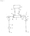
- a hematocrit sensor is placed in the blood circuit 1 and measures the hematocrit value, which indicates the concentration of the patient's blood flowing through the blood circuit 1.
- the blood circuit 1 mainly comprises an arterial blood circuit 1a and a venous blood circuit 1b.
- a dialyzer 2 is connected between the arterial blood circuit 1a and the venous blood circuit 1b.
- An arterial needle a is connected at the terminal of the arterial blood circuit 1a and a roller blood pump 3 is positioned at some point in the middle of the arterial blood circuit 1a. Additionally, a venous needle b is connected at the terminal of the venous blood circuit 1b and a drip chamber 4 is connected at some point in the middle of the venous blood circuit 1b.
- the blood pump 3 When the blood pump 3 is driven while the arterial needle a and the venous needle b are inserted into the patient, the patient's blood flows through the arterial blood circuit 1a and into the dialyzer 2.
- the dialyzer 2 purifies the blood and returns it to the patient through the venous blood circuit 1b after air bubbles are removed by the drip chamber 4.
- the blood of the patient is purified by the dialyzer 2 while extracorporeally circulating through the blood circuit 1.
- an air bubble detector 5 is placed near the venous needle b in the venous blood circuit 1b.
- the air bubble detector 5 monitors the presence of air in the blood flowing through the venous blood circuit 1b and can, for example, be formed from a sensor that detects air by applying ultrasound waves to the flexible tubing.
- the housing for the air bubble detector comprises a blood detector to detect the presence of blood using light irradiation (blood detector not shown).
- the blood detector can be either a transmission type or a reflection type.
- the dialyzer case comprises a blood inlet port 2a, a blood outlet port 2b, a dialyzing fluid inlet port 2c, and a dialyzing fluid outlet port 2d.
- the blood inlet port 2a and the blood outlet port 2b are connected to the arterial blood circuit 1a and the venous blood circuit 1b, respectively.
- the dialyzing fluid inlet port 2c and the dialyzing fluid outlet port 2d are connected to a dialyzing fluid inlet line L1 and a dialyzing fluid outlet line L2, respectively. Lines L1 and L2 extend from a dialysis monitor 6.
- the dialyzer 2 comprises multiple hollow fibers.
- the blood flows inside of the hollow fibers and the dialyzing fluid flows between the outside surface of the hollow fibers and the inside surface of the dialyzer case.
- the hollow fibers include many tiny pores that penetrate the outside and inside surfaces of the hollow fiber membrane, and through which waste products in the blood are dialyzed out to the dialyzing fluid.
- the dialysis monitor 6 comprises a duplex pump P that is connected between the dialyzing fluid inlet line L1 and the dialyzing fluid outlet line L2.
- a bypass line L3 is connected to the dialyzing fluid outlet line L2, and bypasses the duplex pump P.
- An ultrafiltration pump 8 is connected to the bypass line L3.
- a first end of the dialyzing fluid inlet line L1 is connected to the dialyzer 2 at the dialyzing fluid inlet port 2c.
- a second end of the dialyzing fluid inlet line L1 is connected to a dialyzing fluid supplier (not shown), which prepares the dialyzing fluid of predetermined concentration.
- a first end of dialyzing fluid outlet line L2 is connected to the dialyzer 2 at the dialyzing fluid outlet port 2d.
- a second end of dialyzing fluid outlet line L2 is connected to a waste fluid disposal means (not shown).
- dialyzing fluid supplied from the dialyzing fluid supplier passes through the dialyzing fluid inlet line L1 to the dialyzer 2, the passes through the dialyzing fluid outlet line L2 and the bypass line L3, and is let out to the waste fluid disposal means.
- reference numerals 9 and 10 indicate a heater and a deaeration means, both connected to the dialyzing fluid inlet line L1.
- the ultrafiltration pump 8 removes water from the patient's blood flowing through the dialyzer 2.
- the volume of dialyzing fluid let out of the dialyzing fluid outlet line L2 is greater than the volume of the dialyzing fluid introduced from the dialyzing fluid inlet line L1. Accordingly, water is removed from the patient's blood by the difference between the outlet and inlet volumes.
- the hematocrit sensor 7 is located in the middle of the arterial blood circuit 1a and monitors the patient's blood condition during water removal.
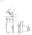
- the hematocrit sensor 7 as shown in FIGS. 3 to 5 comprises a housing 11, a slit 12, a light emission means 13 (light emission element), a light reception means 14 (light reception element), a cover 15, and a hook 16 as a holding means.
- the housing 11 is a resin formed product and comprises the main component of the hematocrit sensor.
- the slot 11a is formed in the longitudinal direction of the surface of the housing 11.
- the slot 11a contains part of the flexible tube C in the blood circuit and is molded with the housing 11 when it is built.
- the slot 11a preferably has a linear structure having approximately the same width throughout.
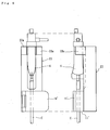
- the surface of the housing 11 shown on the right side of FIG. 4 comprises a concave part 11b, inside of which pins 17 are fixed.
- the surface of the housing shown on the left side of FIG. 5 comprises convex parts 11c and 11d to allow the cover 15 to swing freely.
- the cover 15 can cover the front surface side of the housing 11 (the surface side having the slot 11a) and can also swing freely against the housing 11. Specifically, the swing pin 18 shown in FIG. 3a is inserted along the edge of the convex parts 11c and 11d and the cover 15, such that the cover 15 can rotate around the swing pin 18. Accordingly, the cover 15 can be opened or closed, allowing the slot 11a to be covered or uncovered.
- the edge of the cover 15 (the opposite edge of the edge having the swing pin 18) comprises a fixed pin 19 at the center of a freely movable hook 16.
- the hook 16 can hold the cover 15 against the housing 11 while the cover 15 is closed (i.e., covering the surface of the housing 11), such that the top part 16a, which has a key-like shape, is held by the pin 17.
- the cover 15 is removable and can freely swing open against the housing, leaving the slot 11a covered when the cover 15 is closed and attached to the housing and uncovered when the cover 15 is swung open against the housing.
- the slit 12 is formed by cutting a defined length along the bottom surface of the slot 11a in the direction of the extension of the slot 11a. Further inside the slit 12 of the housing 11 is a space S (see FIG. 5 ) that contains the light emission means 13 and light reception means 14, wherein the slit 12 fully connects the space S and the slot 11a.
- the plurality of pores formed at the bottom surface of the slot 11a may be employed, wherein the light irradiated from the light emission means and the reflected light can both pass through the plurality of pores to the light reception means.
- the slot 11a comprises a clear adhesive seal (not shown) to prevent water and other undesirable materials from entering the space S through the slot 11a.
- the light emission means 13 can comprise a light emitting diode (LED) (near infrared LED) that can irradiate a near infrared ray of approximately 805 ⁇ 15 nm wavelength.
- the light reception means 14 can comprise a photo diode. As shown in FIG. 6 , the light emission means 13 and the light reception means 14 are located at a defined distance from each other on a base board 20, and are set in the space S. Both the light emission means 13 and the light reception means 14 can face the outside of the space S (specifically, the flexible tube C contained in the slot 11a) through the slit 12.
- the base board 20 functions as an amplification circuit to amplify the signal from the light reception means 14.
- the light reception means 14 receives the light and outputs a signal in accordance with the illumination.
- the signal can be amplified by using the amplification circuit.
- a near infrared LED when employed as the light emission means 13, it can irradiate the light at a wavelength that may not affect the light absorption ratio of hemoglobin.
- an accurate hematocrit value can be constantly measured without being effected by the oxygenation level of hemoglobin in the blood.
- the light irradiated from the light emission means 13 passes to the flexible tube C, which is contained in the slot 11a, through the slit 12 and then reflects off of the blood flowing in the inside of the flexible tube C.
- the reflected light is then received by the light reception means 14 (a so-called reflection type sensor). Accordingly, in comparison with a so-called transmission type sensor, the reflection type sensor can prevent deformation of the flexible tube comprising the blood circuit and also allows the overall size of the sensor to be reduced.
- the conventional light transmission type hematocrit sensor must strongly sandwich the flexible tube in order to increase the measuring accuracy using a light emission means and light reception means that face each other.
- the light reflection type hematocrit sensor comprises a flexible tube that is not strongly sandwiched by a light emission means and light reception means that face each other, and therefore this reflection type sensor does not bend and deform the flexible tube.
- the light transmission type sensor must comprise one housing with an independent light emission means and another housing with an independent light reception means, thus increasing the total size of the sensor.
- the light reflection type sensor comprises only one housing having both a light emission means and a light reception means, thus allowing for the total size of the sensor to be reduced.
- the light transmission type sensor must comprise another part, a cuvette, in the measuring portion, such that the emitted and received light must pass through the cuvette.
- the light reflection type sensor does not require an extra part such as a cuvette, and thereby can reduce the number of parts and increase the operational productivity of the sensor.
- a hematocrit value can be obtained based on an electric signal output from the light reception means 14.
- each component of blood such as red blood cells and blood plasma, has its own characteristic light absorption.
- red blood cells which are required for measuring hematocrit value, can be electro-optically quantified, thus allowing the hematocrit value to be determined.
- near infrared light irradiated from the light emission means reflects off of the blood, it is effected by absorption and scattering before it is received by the light reception means.
- a hematocrit value can be calculated by analyzing the light absorption and scattering ratio based on the strength of the received light.
- a water removal rate which is appropriate for the patient's condition, can be determined.
- the substitution fluid condition or dialyzing fluid condition may also be determined based on the measured hematocrit value.
- the hematocrit sensor 7 has a fixed metal plate 21 on the outside of the housing 11.
- the plate 21 has a holder 22 formed by bending a metal plate.
- Such holder 22 has a fixed screw N, wherein the top of the screw N and the holder 22 are structured so as to hold a stand ST in order to fix the hematocrit sensor in place.
- the hematocrit sensor of the present invention is connected to the arterial blood circuit 1a.
- This connecting operation requires that the flexible tube C consisting of a part of the arterial blood circuit 1a is inserted along the slot 11a while the cover 15 is open (specifically, while the slot 11a is uncovered), and then the cover 15 is swung closed. Further, the hematocrit sensor 7 is fixed to the stand ST by fastening the fixed screw N.
- the cover 15 can close the slot 11a, including the slit 12, by closing the cover 15. Accordingly, the cover 15 and the housing 11 can sandwich the flexible tube C ( FIG. 3a ). In this case the preferred sandwiching force is in a range that will not deform the flexible tube C.
- the width and depth of the slot 11a are preferably designed to be approximately the same as the outer diameter of the flexible tube C.
- the slot 11a including the slit 12 is closed with the cover 15, such that the effect of the ambient light can be controlled, and emission and reception of the light between the light emission means 13 and the light reception means 14 are accurate.
- a more accurate hematocrit value can be measured.
- another cover that can cover the slot 11a, including the slit 12, other than the cover of this embodiment if the cover can entirely cover the slot 11a of the housing 11.
- a cover that only covers the upper part of the slot 11a may be also employed.
- the hook 16 is swung to hold the cover 15 against the housing 11. Accordingly, after the hematocrit sensor is connected to the blood circuit 1, the sensor can be prevented from slipping out of position or the cover 15 can be prevented from being carelessly opened. Thus, a more accurate measurement of the hematocrit value can be obtained.
- the cover 15 can swing freely against the housing 11, such that the slot 11a, including the slit 12, can be opened and closed.
- the cover 15 can be swung closed after the hematocrit sensor is connected to the blood circuit 1 and during measurement of the hematocrit value.
- the cover 15 can be swung open and the flexible tube C can be removed when the hematocrit value is not being measured or when the hematocrit sensor is disconnected from the blood circuit.
- operational productivity can be increased by connecting the sensor to the blood circuit and disconnecting it from the blood circuit.
- the hematocrit sensor is connected to the arterial blood circuit 1a. Dialysis treatment is then performed, wherein the hematocrit sensor 7 can perform real-time measurements of the hematocrit value. Specifically, the light (near infrared ray) from the light emission means 13 is irradiated to the blood flowing through the flexible tube C in the slot 11a. The light reception means 14 receives the reflected light. The light reception means 14 then outputs an electric signal of voltage in accordance with the illumination of the received light. The hematocrit value can be determined based on this output signal.
- an extra part such as a cuvette for a transmission type sensor, is not required.
- the measurement can be performed simply using the flexible tube. Therefore, the number of parts can be reduced and costs can be lowered,. Of course, the measurement accuracy can be increased by using specialty parts, such as a cuvette.
- FIG. 7 A graph showing the relationship between hematocrit value and output voltage is shown in FIG. 7 .
- This graph shows each relationship between hematocrit values (%) measured from a hematocrit sensor having varying slit widths: no slit, 2 mm, 3 mm, and 4 mm, and the corresponding output voltage from the light reception means 14.
- the output voltage is proportional.
- the hematocrit value may vary in the range of 10 to 60%, but the aforementioned slit width the relationship will still be proportional.
- a slit width is in the range of 2 to 4 mm is preferable because a more linear output voltage can be obtained in the practical range of the hematocrit value.
- a slit width of 3 mm is most preferable.
- a slit width of 2 to 4 mm is preferred, other slid widths can be employed depending on the diameter of the flexible tube. Additionally, when a plurality of pores is employed instead of a slit, a pore diameter of 2 to 4 mm is preferred.
- the blood pump is driven to pump the patient's blood and circulate it extracorporeally.
- the blood is collected through the arterial needle a and flows through the arterial blood circuit 1a to the dialyzer 2. From there, the blood flows through the venous blood circuit 1b and returns to the patient through the venous needle b.
- materials such as contaminants are eliminated from the blood by the dialyzer 2. Additionally, water also can be removed from the blood.
- Such water removal is performed by driving the ultrafiltration pump 8. A certain amount of water is forcefully removed from the blood that flows through the blood circuit of the dialyzer 2 (i.e., through the inside of the hollow fiber).
- the water removal rate is controlled based on the hematocrit value measured by the hematocrit sensor. More specifically, the control is based on the rate of change of the circulating blood volume.
- the hematocrit sensor 7 measures the hematocrit value in real-time, which indicates the patient's blood concentration. Feedback based on the measured value is sent to the driving control means for the ultrafiltration pump 8. Thus, water can be removed at an appropriate rate based on the patient's condition. If the measured value is normal, water is removed at the pre-set rate. But if the hematocrit value rises above normal, the increased blood concentration may cause the patient to suffer shock or a drop in blood pressure. In that case, the water removal rate would be decreased by controlling the driving of the ultrafiltration pump 8.
- the hematocrit sensor 7 is in the arterial blood circuit 1a, it can be positioned in the venous blood circuit 1b. In this situation, the arterial hematocrit value (Hta) must be calculated from the venous hematocrit value (Htv) using, for example, the following formulas:
- Htv Qb Qb - Qu ⁇ Hta
- the blood flow rate (Qb) and water removal rate (Qu) through the arterial blood circuit 1a are known. Therefore, Htv can be measured and Hta can be calculated.
- the hematocrit sensor comprises a housing 11 and a fixing means 23 (i.e., a stand for a drip chamber 4) are integrally formed, and a drip chamber 4 is connected to the blood circuit 1.
- the housing 11 is formed as a lobe at one end of the integrally formed fixing means 23 and drip chamber 4.
- FIG. 8 also shows a pair of lobes 23a that hold the drip chamber 4, wherein the slot formed in the housing 11' connects a part of the extended flexible tube C from the lower end of the drip chamber 4.
- the cover 15' can close the slot when the cover 15' is closed and is able to freely swing against the housing 11'.
- the same slit as in previous embodiments is formed in the slot of the housing 11'.
- Light emission and light reception which occurs between the light emission means and the light reception means, is performed through the slit. Accordingly, the hematocrit value of the blood flowing through the flexible tube C can be measured. Based on the measured hematocrit value, the ultrafiltration pump can be controlled.
- the slot, light emission means, and light reception means are not shown in the figure because they are similar to those shown and described in previous figures described above.
- the cover 15' has no means for being held against the housing 11' as in a previous embodiment, the hook 16 can be built and added to the assembly as a means for holding.
- the hematocrit sensor is integrally formed with the fixing means 23 for the drip chamber 4, which is connected to the venous blood circuit 1b, the drip chamber can alternatively be connected to the arterial blood circuit 1a. Even in this situation, the hematocrit sensor can still be integrally formed with the fixing means 23 for the drip chamber 4.
- the hematocrit sensor housing and the air bubble detector connected to the venous blood circuit 1b can also be commonly integrally formed.
- the hematocrit sensor and other structuring means connected to the blood circuit 1 can be integrally formed as well.
- the hematocrit sensor can be integrally formed with the fixing means for the drip chamber or the air bubble detector. Accordingly, the blood circuit and surrounding components can be simplified and reduced in size in comparison with hematocrit sensors having parts that are separate and not commonly integrally formed. By unifying various components, both the integrally formed components and the hematocrit sensor can be set in place at the same time, allowing for a complicated arrangement step to be simplified.
- the hematocrit sensor comprises a housing 11, a slit 12', a base board 20 comprising a light emission means 13 (a light emitting element) and a light reception means 14 (a light receiving element), and a cover 15.
- the housing comprises a slot 11a, as described above in connection with previous embodiments, and a space S that can contain the base board 20.
- the components shown in FIGS. 9 and 10 which appear in previous figures, have been assigned the same reference numerals as in those previous figures. Accordingly, a detailed description of these components is not given. Additionally, the hook used to hold the cover 15 against the housing 11 is not shown.
- the hematocrit sensor comprises the slit 12' having an adjustable width.
- the slit 12' comprises a gap between two boards 24a and 24b.
- the gap width can be made narrower by bringing boards 24a and 24b closer together, and wider by keeping boards 24a and 24b further apart from each other.
- Boards 24a and 24b comprise long holes 24aa and 24ba respectively. Screws n1 and n2 can be connected to long holes 24aa and 24ba through washers W1 and W2, respectively. Thus, the width between boards 24a and 24b can be freely adjusted and fixed. Specifically, boards 24a and 24b can be slid within the length of the long holes 24aa and 24ba, and can also be fixed at any desired position within that length using screws n1 and n2.
- the slit width can be easily adjusted to give a proportional relationship between the hematocrit value (%) and the output voltage of the light reception means 14.
- the flexible tube C comprising the blood circuit 1 can have one of various inside diameters due to different wall thicknesses even though the flexible tube C maintains the same outside diameter.
- the flexible tube C can have one of various different reflections of light from the light emission means 13 due to the different surface (due to an embossing process, for example).
- the width and the depth of the slot 11a, which holds the flexible tube C, can vary as weU in response to different types of flexible tube C having different outside diameters.
- the slit width of the upper part of the light emission means 13 and the slit width of the upper part of the light reception means 14 can be made independently adjustable.
- the medial axis of the slit 12' and the medial axis of the flexible tube C held by the slot 11a do not always have to be positioned along the same straight line. Rather, they can be made adjustable due to the direction of the light emission means 13 fixed on the board 20.
- each pore can be made adjustable using a variable diaphragm. In this case, the position of the pores in addition to the diameter of the pores could be adjustable, thus allowing for fine adjustment.
- the hematocrit sensor comprises a flashing means that turns the light emission means on and off.
- the hematocrit sensor monitors the output voltage from the light reception means when the light emission means is turned off. For example, as shown in FIG. 13 , the output voltage of the light emission means can be monitored when the light emission means is turned off by determining the output voltage waveform (K1) of the light reception means when there is no ambient light.
- output voltage waveform K2 can be regenerated, as if it is output voltage waveform K1, while the light emission means is turned off.
- the regenerated output voltage waveform (K3) is a detectable waveform. The regeneration can be performed on each flashing of the light emission means, and the regenerated output voltage can be compensated each time. Furthermore, instead of the regeneration of the output voltage waveform K3 from the output voltage waveform K2 based on the output voltage waveform K1, the difference between the on-state and off-state of the light emission means can be used to determine the output voltage.
- the composition of the hematocrit sensor itself can be as the same as one of the previous embodiments, or it can be different, wherein controlling the light emission means and monitoring the light reception means is performed as described above.
- a seal for protecting the slit from irradiation of ambient light can be simplified or removed, thereby simplifying the composition of the hematocrit sensor itself.
- the hematocrit sensor measures the hematocrit value based on differences in blood flow rates through the flexible tube C.
- the relationship between an output voltage of the light reception means and a hematocrit value depends on the blood flow rate (QB). For example, as shown in FIG. 14 , when QB equals q1 or q2, the relationship between the output voltage and the hematocrit value is expressed differently when QB equals q1 versus when QB equals q2.
- the relationship between the output voltage of the light reception means and the hematocrit value when QB equals q1 can be stored in the sensor. While the initial QB equals q1, the hematocrit value is continuously measured. When QB equals q2, the hematocrit value can be continuously measured as if QB equals q1 by automatically controlling the blood pump in the blood circuit.
- the blood pump is automatically controlled to change QB from q1 to q2.
- the hematocrit value is the same at both q1 and q2, the calculation of the hematocrit value deviates depending on the blood flow rate. Accordingly, after changing the flow rate to q2, the hematocrit value can be recalculated with compensation as if QB equals q1, and hematocrit values can be continuously measured. After recalculation, a variation ( ⁇ Ht/ ⁇ V) of the hematocrit value per voltage unit employs the same constant value a as when QB equals q1.
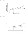
- the compensation can be performed at a time when the variation of the hematocrit value exceeds a certain range, or when the measuring duration exceeds a certain length of time. For example, as shown in FIG. 15 , when compensations are performed at measurement times t1, t2, and t3, the variation of the actual hematocrit value is H2. When QB employs constant value a (when QB equals q1), the compensated measurement value changes as H1.
- the hematocrit value just after QB changes (H4 in FIG. 16 ) is compensated to become the hematocrit value just before QB changed (H3 in FIG. 16 ), and the hematocrit measurements are continuously obtained.
- the compensation of the hematocrit value is repeatedly performed.
- the hematocrit sensor is independent from a blood purifier, the sensor can be electrically connected to the blood purifier in order to continuously collect blood flow rate information.
- the detected hematocrit value can be compensated, thereby avoiding measurement errors due to a difference in blood flow rates. Consequently, more accurate hematocrit value measurements can be obtained.
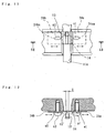
- the hematocrit sensor comprises a housing 11 having a slot 11a with a slit 12, a base board 20 comprising a light emission means 13 and a light reception means 14, a cover 15, and a detection switch 25 as a means for detecting whether the cover is open or closed.
- the components shown in FIGS. 17 and 18 which appear in previous figures, have been assigned the same reference numerals as in those previous figures. Accordingly, a detailed description of these components is not given. Additionally, the hook used to hold the cover 15 against the housing 11 is not shown.
- the switch 25 detects whether or not the flexible tube C in the blood circuit is contained in the slot 11a, and whether or not the cover 15 is closed.
- the switch 25 comprises a push button portion 25a positioned slightly above the bottom of the slot 11a. After the flexible tube C is placed into the slot 11a and the cover 15 is closed; the push button portion 25a is pressed through the flexible tube C, and turns on the detection switch. Furthermore, the flexible cover 26 seals the detection switch 25, preventing water or undesirable materials from entering through the slot 11a.
- the detection switch When the detection switch is turned on, it can recognize that the cover 15 is closed after the flexible tube C is set in place. Accordingly, instances of forgetting to set the flexible tube C in the slot 11a of the hematocrit sensor and then closing the cover 15 can be avoided. Also, measuring errors due to irradiation of ambient light can be avoided as well.
- the hematocrit sensor can be connected to a blood purifier and the hematocrit value is being measured, the blood purifier can be used to visually or audibly notify the operators when they forget to set the flexible tube C and to close the cover 15.
- the hematocrit sensor (including both type where components are integrally formed and the type where components are separate) can be co-driven with a blood detector (not shown) that is connected to the blood circuit 1.
- the blood detector can be built in the housing of air bubble detector 5, and analyzes the presence of blood in the blood circuit 1. Accordingly, the starting point for the hematocrit measurement can be adjusted as necessary.
- the hematocrit sensor is integrally formed with a blood detector, the effect of recirculation in the shunt part of the blood circuit when saline solution is directed to the patient's body (i.e., when the blood diluted with saline is incorporated into the blood circuit, the hematocrit value decreases) can be eliminated.
- the blood detector conventionally is connected to the venous blood circuit 1b, and it is desirable for the blood detector and the hematocrit sensor to be integrally formed.
- the blood detector and the hematocrit sensor can still be integrally formed, for example, where the blood detector is built in the housing.
- the present invention is not limited to these embodiments.
- the dialysis device used in these embodiments is a so-called central system, which separately comprises a dialyzing fluid supplier and a dialysis monitor, but an integrally formed system (a so-called personal dialysis apparatus) can be used instead.
- the duplex pump P in the dialysis monitor supplies dialyzing fluid to the dialyzer 2, but a so-called balancing chamber can also be employed to supply dialyzing fluid.
- a double needle type comprising an arterial needle and a venous needle is described in the present embodiments, but a single needle type which having only one needle can also be used.
- the hematocrit sensor of the present invention is not limited to uses in connection with dialysis treatment, and can also be applied to various blood purifiers which extracorporeally circulate the blood. Additionally, the blood circuit is not limited to the flexible tube. Rather, various circuits through which blood is able to flow an be employed as a blood circuit.
- a hematocrit sensor comprising the flexible tube C in the blood circuit 1, which is contained in the slot 11a built in the housing 11, can be used without the component cover 15.
- the light emitting from the light emission means and the light reception at the light reception means can be performed through the slit 12.
- a means to fix the stand ST e.g., holder 22 and screw N
- the light emission means and the light reception means are not limited to a LED and photodiode in accordance with the present embodiments and other light emission and light reception means which can measure the reflected light of irradiated light and the hematocrit value can be employed.
Landscapes
- Health & Medical Sciences (AREA)
- Heart & Thoracic Surgery (AREA)
- Vascular Medicine (AREA)
- Life Sciences & Earth Sciences (AREA)
- General Health & Medical Sciences (AREA)
- Anesthesiology (AREA)
- Biomedical Technology (AREA)
- Hematology (AREA)
- Veterinary Medicine (AREA)
- Animal Behavior & Ethology (AREA)
- Engineering & Computer Science (AREA)
- Public Health (AREA)
- Cardiology (AREA)
- Urology & Nephrology (AREA)
- Emergency Medicine (AREA)
- External Artificial Organs (AREA)
- Measurement Of The Respiration, Hearing Ability, Form, And Blood Characteristics Of Living Organisms (AREA)
Claims (11)
- Hämatokritsensor zum Messen von Hämatokritwerten von Blut, das gereinigt wird, während es in einem extrakorporalen Blutkreislauf (1) zirkuliert, der eine Blutreinigungseinrichtung (2) aufweist, die in der Mitte des Blutkreislaufes (1) angeschlossen ist, aufweisend:ein Gehäuse (11, 11'), das an einen Abschnitt des Blutkreislaufes (1) angeschlossen werden kann; undeine Nut (11a), die in das Gehäuse (11, 11') eingebaut ist, dadurch gekennzeichnet, dassder Hämatokritsensor weiter aufweist:einen Schlitz (12, 12') oder eine Mehrzahl von Poren, die in die Nut (11a) des Gehäuses (11, 11') eingebaut sind; undeine Lichtaussendeeinrichtung (13) und eine Lichtaufnahmeeinrichtung (14), die in das Gehäuse (11, 11') eingebaut sind, derart, dass diese beiden Einrichtungen (13, 14) dem Blutkreislauf (1) zugewandt sind, und zwar durch den Schlitz (12, 12') oder die Mehrzahl von Poren,wobei das Licht, das von der Lichtaussendeeinrichtung (13) ausgesendet wird, und das reflektierte Licht, das zur Lichtempfangseinrichtung (14) zurückkehrt, durch den Schlitz (12, 12') oder die Mehrzahl von Poren hindurch verläuft, wobei die Breite des Schlitzes (12, 12') oder der Durchmesser der Mehrzahl von Poren willkürlich eingestellt werden kann.
- Hämatokritsensor nach Anspruch 1, der weiter eine Abdeckung (15, 15') aufweist, die an dem Gehäuse (11, 11') befestigt ist und die die Nut abdeckt, wenn die Abdeckung geschlossen ist.
- Hämatokritsensor nach Anspruch 2, der weiter eine Abdeckung (15, 15') aufweist, die an dem Gehäuse (11, 11') befestigt ist und die gegen das Gehäuse (11, 11') ausschwenkt und die Nut (11a) freigibt, wenn die Abdeckung (15, 15') geöffnet ist.
- Hämatokritsensor nach Anspruch 2 oder 3, der weiter eine Halteeinrichtung (16) aufweist, welche die Abdeckung (15, 15') an ihrem Ort hält, wenn die Nut (11a) bedeckt ist.
- Hämatokritsensor nach einem der Ansprüche 2 bis 4, der weiter eine Erfassungseinrichtung aufweist, die erfasst, ob sich der Blutkreislauf (1) in der Nut (11a) befindet oder nicht, und ob die Abdeckung (15, 15') geschlossen ist oder nicht.
- Hämatokritsensor nach einem der Ansprüche 1 bis 6, weiter aufweisend:eine Tropfkammer (4), die an den Blutkreislauf (1) angeschlossen werden kann; undeine Befestigungseinrichtung (23), vorzugsweise ein Gestell für eine Tropfkammer (4), welches integral mit der Tropfkammer (4) und dem Gehäuse (10, 10') ausgebildet ist.
- Hämatokritsensor nach Anspruch 6, der weiter eine Luftblasenerfassungseinrichtung (5) aufweist, die an den Blutkreislauf (1) angeschlossen werden kann und in das Gehäuse (10, 10') eingebaut ist.
- Hämatokritsensor nach einem der Ansprüche 1 bis 7, der weiter ausgebildet ist, um die gemessenen Hämatokritwerte basierend auf der Stärke des durch die Lichtempfangseinrichtung (14) empfangenen Lichtes auszugleichen, wenn das Licht abgeschaltet wird, während die Lichtaussendeeinrichtung (13) blinkt.
- Hämatokritsensor nach einem der Ansprüche 1 bis 8, der weiter ausgebildet ist, um die gemessenen Hämatokritwerte basierend auf der Durchflussrate des durch den Blutkreislauf (1) strömenden Blutes auszugleichen.
- Blutkreislauf, der einen Hämatokritsensor nach einem der Ansprüche 1 bis 9 aufweist, mit einem Dialysator (2) als Blutreinigungseinrichtung, der in der Mitte des Blutkreislaufes (1) angeschlossen ist, in welchem der Hämatokritsensor (7) die Ultrafiltrationspumpe (8) steuert, um Wasser zu entfernen, einen Zustand eines Substitutionsfluids steuert oder einen Zustand eines Dialysierfluids steuert, basierend auf dem gemessenen Hämatokritwert.
- Blutkreislauf nach Anspruch 10, weiter aufweisend:eine Bluterfassungseinrichtung, die an den Blutkreislauf (1) angeschlossen ist, wobei die Bluterfassungseinrichtung das Vorhandensein von Blut im Blutkreislauf (1) erfasst; undder erste der gemessenen Hämatokritwerte zu dem Zeitpunkt berechnet wird, bei dem die Bluterfassungseinrichtung als erstes ein Strömen von Blut durch den Blutkreislauf (1) erfasst.
Applications Claiming Priority (5)
| Application Number | Priority Date | Filing Date | Title |
|---|---|---|---|
| JP2002209330 | 2002-07-18 | ||
| JP2002209330 | 2002-07-18 | ||
| JP2003134906 | 2003-05-13 | ||
| JP2003134906A JP4129867B2 (ja) | 2002-07-18 | 2003-05-13 | ヘマトクリットセンサ |
| PCT/JP2003/007759 WO2004009154A1 (ja) | 2002-07-18 | 2003-06-19 | ヘマトクリットセンサ |
Publications (3)
| Publication Number | Publication Date |
|---|---|
| EP1529544A1 EP1529544A1 (de) | 2005-05-11 |
| EP1529544A4 EP1529544A4 (de) | 2008-07-16 |
| EP1529544B1 true EP1529544B1 (de) | 2011-08-10 |
Family
ID=30772208
Family Applications (1)
| Application Number | Title | Priority Date | Filing Date |
|---|---|---|---|
| EP03765272A Expired - Lifetime EP1529544B1 (de) | 2002-07-18 | 2003-06-19 | Hämatokritsensor |
Country Status (7)
| Country | Link |
|---|---|
| US (1) | US7381195B2 (de) |
| EP (1) | EP1529544B1 (de) |
| JP (1) | JP4129867B2 (de) |
| KR (1) | KR100975119B1 (de) |
| CN (1) | CN100486649C (de) |
| TW (1) | TWI310318B (de) |
| WO (1) | WO2004009154A1 (de) |
Families Citing this family (36)
| Publication number | Priority date | Publication date | Assignee | Title |
|---|---|---|---|---|
| JP3958733B2 (ja) * | 2002-11-14 | 2007-08-15 | 日機装株式会社 | 血液浄化装置 |
| US8029454B2 (en) | 2003-11-05 | 2011-10-04 | Baxter International Inc. | High convection home hemodialysis/hemofiltration and sorbent system |
| JP4868772B2 (ja) * | 2004-08-24 | 2012-02-01 | 日機装株式会社 | 血液浄化装置 |
| JP4925159B2 (ja) * | 2005-10-12 | 2012-04-25 | 日機装株式会社 | 血液浄化装置 |
| US8114276B2 (en) | 2007-10-24 | 2012-02-14 | Baxter International Inc. | Personal hemodialysis system |
| JP5096286B2 (ja) * | 2008-10-28 | 2012-12-12 | 日機装株式会社 | 気泡検出装置及び生体成分測定装置 |
| US9370324B2 (en) | 2008-11-05 | 2016-06-21 | Fresenius Medical Care Holdings, Inc. | Hemodialysis patient data acquisition, management and analysis system |
| JP5222706B2 (ja) * | 2008-12-04 | 2013-06-26 | 日機装株式会社 | 血液浄化装置及びその血液流量演算方法 |
| ITMI20090926A1 (it) | 2009-05-26 | 2010-11-27 | Datamed Srl | Apparato e metodo per misure spettrofotometriche di parametri del sangue. |
| US9713670B2 (en) | 2009-11-24 | 2017-07-25 | Fresenius Medical Care Deutschland Gmbh | Method for temporarily interrupting an extracorporeal blood treatment, control device and blood treatment apparatus |
| US8753515B2 (en) | 2009-12-05 | 2014-06-17 | Home Dialysis Plus, Ltd. | Dialysis system with ultrafiltration control |
| US8366649B2 (en) * | 2009-12-09 | 2013-02-05 | Araz Ibragimov | Manually operated disposable single-needle circuit for extracorporeal treatment of blood |
| JP6027720B2 (ja) * | 2009-12-14 | 2016-11-16 | 日機装株式会社 | 血液浄化装置 |
| US8501009B2 (en) | 2010-06-07 | 2013-08-06 | State Of Oregon Acting By And Through The State Board Of Higher Education On Behalf Of Oregon State University | Fluid purification system |
| EP2763719B1 (de) | 2011-10-07 | 2017-08-09 | Outset Medical, Inc. | Wärmeaustauschflüssigkeitsreinigung für ein dialysesystem |
| DE102011119824B4 (de) * | 2011-12-01 | 2013-07-04 | Fresenius Medical Care Deutschland Gmbh | Verfahren und Vorrichtung zur Bestimmung eines Blutbestandteils |
| DE102012104461A1 (de) | 2012-05-23 | 2013-12-12 | B. Braun Avitum Ag | Medizinisches Gerät zur extrakorporalen Blutbehandlung mit mehreren Sensoreinheiten |
| DE102013103335A1 (de) | 2013-04-03 | 2014-10-09 | B. Braun Avitum Ag | System zur Erfassung eines Zustands einer Dialysatorvorrichtung, und hierfür verwendbare Sensorvorrichtung |
| JP2015021932A (ja) * | 2013-07-23 | 2015-02-02 | パイオニア株式会社 | 気泡検出器及び気泡検出方法 |
| JP6657186B2 (ja) | 2014-04-29 | 2020-03-04 | アウトセット・メディカル・インコーポレイテッドOutset Medical, Inc. | 透析システムおよび方法 |
| JP6067620B2 (ja) * | 2014-06-12 | 2017-01-25 | 日機装株式会社 | 血液浄化装置 |
| US10583239B2 (en) * | 2015-02-27 | 2020-03-10 | MAQUET CARDIOPULMONARY GmbH | Fluid flow rate measuring and gas bubble detecting apparatus |
| US11047798B2 (en) | 2016-08-18 | 2021-06-29 | Konica Minolta, Inc. | Measurement method, measurement apparatus, and measurement system |
| US11534537B2 (en) | 2016-08-19 | 2022-12-27 | Outset Medical, Inc. | Peritoneal dialysis system and methods |
| US10137257B2 (en) * | 2016-11-30 | 2018-11-27 | Belmont Instrument, Llc | Slack-time heating system for blood and fluid warming |
| JP2018201823A (ja) * | 2017-06-02 | 2018-12-27 | 株式会社ジェイ・エム・エス | 超音波測定装置及び体外循環装置 |
| AU2019325668B2 (en) | 2018-08-23 | 2025-03-27 | Outset Medical, Inc. | Dialysis system and methods |
| AU2020266584B2 (en) | 2019-04-30 | 2025-10-23 | Outset Medical, Inc. | Dialysis system and methods |
| CN112305246B (zh) * | 2019-07-30 | 2025-06-13 | 深圳迈瑞生物医疗电子股份有限公司 | 样本分析方法及样本分析系统 |
| CN112305245B (zh) * | 2019-07-30 | 2024-04-19 | 深圳迈瑞生物医疗电子股份有限公司 | 样本分析方法及样本分析系统 |
| CN116249893B (zh) * | 2020-07-08 | 2025-12-23 | 艾赛普公司 | 用于测定循环液体的血红蛋白水平或血细胞比容水平的装置 |
| EP3991764B1 (de) | 2020-10-27 | 2024-03-06 | Bellco S.r.l. | Durchflussmesser zum dosieren von wasser in einem dialysesystem |
| ES3007240T3 (en) | 2020-10-30 | 2025-03-19 | Bellco Srl | Dialysis cassette with pump features |
| US12318528B2 (en) | 2020-10-30 | 2025-06-03 | Mozarc Medical Us Llc | Variable orifice fistula graft |
| EP4008376A1 (de) | 2020-12-03 | 2022-06-08 | Medtronic, Inc. | Flexibles rohr-routing-zubehör für peritoneal dialysis system |
| JP7625941B2 (ja) * | 2021-04-01 | 2025-02-04 | 東レ株式会社 | ヘマトクリットセンサ |
Family Cites Families (18)
| Publication number | Priority date | Publication date | Assignee | Title |
|---|---|---|---|---|
| GB1515860A (en) * | 1975-11-28 | 1978-06-28 | Perkin Elmer Ltd | Spectrophotometers |
| US4118625A (en) * | 1977-05-02 | 1978-10-03 | Dynatech Laboratories Incorporated | Nephelometer having pulsed energy source |
| US4745279A (en) * | 1986-01-02 | 1988-05-17 | American Hospital Supply Corporation | Hematocrit measuring apparatus |
| JPH071274B2 (ja) | 1986-04-25 | 1995-01-11 | 節雄 高谷 | ヘモグロビン濃度測定方法 |
| US5291884A (en) * | 1991-02-07 | 1994-03-08 | Minnesota Mining And Manufacturing Company | Apparatus for measuring a blood parameter |
| US5385539A (en) * | 1992-06-30 | 1995-01-31 | Advanced Haemotechnologies | Apparatus for monitoring hematocrit levels of blood |
| DE19619513C2 (de) * | 1996-05-14 | 2001-03-22 | Stoeckert Instr Gmbh | Vorrichtung für die Messung physiologischer Parameter von in einem extrakorporalen Kreislauf geführtem Blut |
| JPH11221275A (ja) | 1997-12-03 | 1999-08-17 | Jms Co Ltd | 血液処理装置 |
| US6006119A (en) * | 1998-02-04 | 1999-12-21 | Polestar Technologies, Inc. | Non-invasive optical measurement of blood hematocrit |
| JPH11226119A (ja) | 1998-02-17 | 1999-08-24 | Nissho Corp | 透析装置の除水量監視機構 |
| US6582385B2 (en) * | 1998-02-19 | 2003-06-24 | Nstage Medical, Inc. | Hemofiltration system including ultrafiltrate purification and re-infusion system |
| US6144444A (en) * | 1998-11-06 | 2000-11-07 | Medtronic Avecor Cardiovascular, Inc. | Apparatus and method to determine blood parameters |
| SE9804142D0 (sv) * | 1998-11-30 | 1998-11-30 | Gambro Ab | Method and device for providing a signal |
| JP4374660B2 (ja) | 1999-06-23 | 2009-12-02 | 株式会社ジェイ・エム・エス | 血液透析装置、血液透析装置を使用した血液処理方法および該血液透析装置を制御する記録媒体 |
| JP2001017404A (ja) * | 1999-07-09 | 2001-01-23 | Koike Medical:Kk | 医療用測定装置 |
| US6294094B1 (en) * | 1999-09-03 | 2001-09-25 | Baxter International Inc. | Systems and methods for sensing red blood cell hematocrit |
| US6554788B1 (en) * | 2000-06-02 | 2003-04-29 | Cobe Cardiovascular, Inc. | Hematocrit sampling system |
| US6660995B1 (en) * | 2001-06-25 | 2003-12-09 | Regents Of The University Of California | Particle size analysis in a turbid media with a single-fiber, optical probe while using a visible spectrometer |
-
2003
- 2003-05-13 JP JP2003134906A patent/JP4129867B2/ja not_active Expired - Lifetime
- 2003-06-19 EP EP03765272A patent/EP1529544B1/de not_active Expired - Lifetime
- 2003-06-19 WO PCT/JP2003/007759 patent/WO2004009154A1/ja not_active Ceased
- 2003-06-19 CN CNB038014173A patent/CN100486649C/zh not_active Expired - Lifetime
- 2003-06-19 KR KR1020047017438A patent/KR100975119B1/ko not_active Expired - Lifetime
- 2003-06-30 TW TW092117758A patent/TWI310318B/zh not_active IP Right Cessation
- 2003-07-18 US US10/623,178 patent/US7381195B2/en not_active Expired - Lifetime
Also Published As
| Publication number | Publication date |
|---|---|
| WO2004009154A1 (ja) | 2004-01-29 |
| KR100975119B1 (ko) | 2010-08-11 |
| US20040067594A1 (en) | 2004-04-08 |
| TWI310318B (en) | 2009-06-01 |
| JP4129867B2 (ja) | 2008-08-06 |
| EP1529544A4 (de) | 2008-07-16 |
| CN100486649C (zh) | 2009-05-13 |
| KR20050025299A (ko) | 2005-03-14 |
| JP2004097782A (ja) | 2004-04-02 |
| CN1578683A (zh) | 2005-02-09 |
| TW200403085A (en) | 2004-03-01 |
| EP1529544A1 (de) | 2005-05-11 |
| US7381195B2 (en) | 2008-06-03 |
Similar Documents
| Publication | Publication Date | Title |
|---|---|---|
| US7381195B2 (en) | Hematocrit sensor | |
| US11839709B1 (en) | System for tailoring dialysis treatment based on sensed potassium concentration, patient data, and population data | |
| EP1790363B1 (de) | Blutreinigungsgerät | |
| EP1566190B1 (de) | Dialysegerät | |
| EP2355690B1 (de) | Hämatokritmessung und schätzung von hämoglobinwerten mit einem nichtinvasiven optischen blutüberwachungssystem | |
| KR100313211B1 (ko) | 혈액성분을관측하기위한일회용체외도관 | |
| US9265872B2 (en) | Device and method for measuring a blood constituent in blood for an extracorporeal blood treating device | |
| EP3610258B1 (de) | Optischer nachweis von luftblasen in kochsalzlösung, blut oder einer mischung aus beidem | |
| US8328748B2 (en) | Off-axis blood chamber | |
| US8517968B2 (en) | Shrouded sensor clip assembly and blood chamber for an optical blood monitoring system | |
| EP1946782B1 (de) | Blutreinigungsgerät zur Berechnung der Rezirkulationsrate | |
| US20130144139A1 (en) | Method and device for determining a blood constituent | |
| EP2434952B1 (de) | Vorrichtung und verfahren für spektrofotometrische messungen von blutparametern | |
| US11596723B2 (en) | Intradialytic monitoring of blood volume change | |
| JP4442825B2 (ja) | 血液浄化装置 |
Legal Events
| Date | Code | Title | Description |
|---|---|---|---|
| PUAI | Public reference made under article 153(3) epc to a published international application that has entered the european phase |
Free format text: ORIGINAL CODE: 0009012 |
|
| 17P | Request for examination filed |
Effective date: 20050216 |
|
| AK | Designated contracting states |
Kind code of ref document: A1 Designated state(s): AT BE BG CH CY CZ DE DK EE ES FI FR GB GR HU IE IT LI LU MC NL PT RO SE SI SK TR |
|
| RBV | Designated contracting states (corrected) |
Designated state(s): DE FR GB IT SE |
|
| A4 | Supplementary search report drawn up and despatched |
Effective date: 20080617 |
|
| 17Q | First examination report despatched |
Effective date: 20081027 |
|
| GRAP | Despatch of communication of intention to grant a patent |
Free format text: ORIGINAL CODE: EPIDOSNIGR1 |
|
| GRAS | Grant fee paid |
Free format text: ORIGINAL CODE: EPIDOSNIGR3 |
|
| GRAA | (expected) grant |
Free format text: ORIGINAL CODE: 0009210 |
|
| AK | Designated contracting states |
Kind code of ref document: B1 Designated state(s): DE FR GB IT SE |
|
| REG | Reference to a national code |
Ref country code: GB Ref legal event code: FG4D |
|
| REG | Reference to a national code |
Ref country code: DE Ref legal event code: R096 Ref document number: 60337998 Country of ref document: DE Effective date: 20111006 |
|
| REG | Reference to a national code |
Ref country code: SE Ref legal event code: TRGR |
|
| PLBE | No opposition filed within time limit |
Free format text: ORIGINAL CODE: 0009261 |
|
| STAA | Information on the status of an ep patent application or granted ep patent |
Free format text: STATUS: NO OPPOSITION FILED WITHIN TIME LIMIT |
|
| 26N | No opposition filed |
Effective date: 20120511 |
|
| REG | Reference to a national code |
Ref country code: DE Ref legal event code: R097 Ref document number: 60337998 Country of ref document: DE Effective date: 20120511 |
|
| REG | Reference to a national code |
Ref country code: FR Ref legal event code: PLFP Year of fee payment: 14 |
|
| REG | Reference to a national code |
Ref country code: FR Ref legal event code: PLFP Year of fee payment: 15 |
|
| REG | Reference to a national code |
Ref country code: FR Ref legal event code: PLFP Year of fee payment: 16 |
|
| PGFP | Annual fee paid to national office [announced via postgrant information from national office to epo] |
Ref country code: SE Payment date: 20220510 Year of fee payment: 20 Ref country code: IT Payment date: 20220510 Year of fee payment: 20 Ref country code: GB Payment date: 20220428 Year of fee payment: 20 Ref country code: FR Payment date: 20220510 Year of fee payment: 20 Ref country code: DE Payment date: 20220505 Year of fee payment: 20 |
|
| REG | Reference to a national code |
Ref country code: DE Ref legal event code: R071 Ref document number: 60337998 Country of ref document: DE |
|
| P01 | Opt-out of the competence of the unified patent court (upc) registered |
Effective date: 20230523 |
|
| REG | Reference to a national code |
Ref country code: GB Ref legal event code: PE20 Expiry date: 20230618 |
|
| REG | Reference to a national code |
Ref country code: SE Ref legal event code: EUG |
|
| PG25 | Lapsed in a contracting state [announced via postgrant information from national office to epo] |
Ref country code: GB Free format text: LAPSE BECAUSE OF EXPIRATION OF PROTECTION Effective date: 20230618 |