EP1529181B1 - Gasturbinenbrennkammer - Google Patents
Gasturbinenbrennkammer Download PDFInfo
- Publication number
- EP1529181B1 EP1529181B1 EP03753347A EP03753347A EP1529181B1 EP 1529181 B1 EP1529181 B1 EP 1529181B1 EP 03753347 A EP03753347 A EP 03753347A EP 03753347 A EP03753347 A EP 03753347A EP 1529181 B1 EP1529181 B1 EP 1529181B1
- Authority
- EP
- European Patent Office
- Prior art keywords
- combustion chamber
- manhole
- manhole cover
- gas turbine
- cover
- Prior art date
- Legal status (The legal status is an assumption and is not a legal conclusion. Google has not performed a legal analysis and makes no representation as to the accuracy of the status listed.)
- Expired - Lifetime
Links
- 238000002485 combustion reaction Methods 0.000 title claims abstract description 86
- 238000001816 cooling Methods 0.000 claims abstract description 32
- 239000012530 fluid Substances 0.000 claims description 2
- 238000007789 sealing Methods 0.000 claims 1
- 239000007789 gas Substances 0.000 description 22
- 239000000446 fuel Substances 0.000 description 4
- 238000005253 cladding Methods 0.000 description 2
- 230000015572 biosynthetic process Effects 0.000 description 1
- 238000000576 coating method Methods 0.000 description 1
- 239000000567 combustion gas Substances 0.000 description 1
- 238000007689 inspection Methods 0.000 description 1
- 238000009434 installation Methods 0.000 description 1
- 239000007788 liquid Substances 0.000 description 1
- 230000000717 retained effect Effects 0.000 description 1
Images
Classifications
-
- F—MECHANICAL ENGINEERING; LIGHTING; HEATING; WEAPONS; BLASTING
- F23—COMBUSTION APPARATUS; COMBUSTION PROCESSES
- F23M—CASINGS, LININGS, WALLS OR DOORS SPECIALLY ADAPTED FOR COMBUSTION CHAMBERS, e.g. FIREBRIDGES; DEVICES FOR DEFLECTING AIR, FLAMES OR COMBUSTION PRODUCTS IN COMBUSTION CHAMBERS; SAFETY ARRANGEMENTS SPECIALLY ADAPTED FOR COMBUSTION APPARATUS; DETAILS OF COMBUSTION CHAMBERS, NOT OTHERWISE PROVIDED FOR
- F23M7/00—Doors
- F23M7/04—Cooling doors or door frames
-
- F—MECHANICAL ENGINEERING; LIGHTING; HEATING; WEAPONS; BLASTING
- F23—COMBUSTION APPARATUS; COMBUSTION PROCESSES
- F23R—GENERATING COMBUSTION PRODUCTS OF HIGH PRESSURE OR HIGH VELOCITY, e.g. GAS-TURBINE COMBUSTION CHAMBERS
- F23R3/00—Continuous combustion chambers using liquid or gaseous fuel
- F23R3/005—Combined with pressure or heat exchangers
Definitions
- the invention relates to a gas turbine combustion chamber with a manhole closable by a manhole cover as access to a combustion chamber interior.
- Gas turbines are used in many areas to drive generators or work machines.
- the energy content of a fuel is used to generate a rotational movement of a turbine shaft.
- the fuel is burned in a combustion chamber, compressed air being supplied by an air compressor.
- the working medium produced in the combustion chamber by the combustion of the fuel, under high pressure and at high temperature, is guided via a turbine unit arranged downstream of the combustion chamber, where it relaxes to perform work.
- a combustion chamber exposed to these temperatures during operation of the gas turbine should, for example for inspection purposes, be accessible from the inside.
- a gas turbine with a combustion chamber is known which has at least a portion which can be tested via a manhole access.
- a gas turbine with an annular combustion chamber is known, wherein an access (manhole) is provided in the flame space through which a person can get into the flame chamber.
- an access manhole
- a manhole in the combustion chamber since this would not withstand the prevailing thermal loads or at least could not ensure the tightness of the combustion chamber.
- the invention has for its object to provide a gas turbine combustor, which is suitable for a gas turbine with a particularly high combustion temperature and allows easy entry of a person.
- a gas turbine combustor having the features of claim 1.
- the gas turbine combustor on a manhole as access to a combustion chamber interior, which is closable with a manhole cover, which has an internal cooling space.
- the interior refrigerator i. the cooling space within the manhole cover, allows targeted cooling of the combustion chamber interior final manhole cover.
- the manhole cover is therefore usable even under high thermal loads in the combustion chamber interior, without deforming to an inadmissible extent. A tight closure of the combustion chamber interior through the manhole cover is guaranteed in all operating conditions.
- the combustion chamber wall in this case has a so-called wall cooling space.
- the internal cooling space of the manhole cover is fluidically connectable, for example by means of connecting lines, with the wall cooling space of the combustion chamber wall.
- a fluidic connection between the internal cooling space of the manhole cover and the wall cooling space of the combustion chamber wall can be produced in a particularly simple manner directly by inserting the manhole cover into the manhole.
- the wall cooling space of the combustion chamber wall without cross-sectional reduction merges into the internal cooling space of the manhole cover.
- the entire wall of the gas turbine combustor including manhole cover forms a homogeneous cooling space.
- the manhole cover or at least one Deckeleinzelteil the manhole cover for example, a cover inner lining, which closes the inner cooling chamber of the manhole cover to the combustion chamber interior, supported by a fastener to the combustion chamber interior, said fastener also holds a manhole cover adjacent interior trim element on the combustion chamber.
- the fastener is preferably at least substantially U-shaped in cross-section, wherein a first U-leg supports the Deckeleinzelteil the manhole cover and a second U-leg holds the inner lining element to the combustion chamber.
- the entire fastening element preferably has the shape of a rail. Due to the design of the fastening element as a U-rail, this has both a sufficient stability and elasticity.
- the fastening element is preferably held on the combustion chamber wall in such a way that a section, in particular a U-leg, of the fastening element protrudes into the manhole and supports the inner cover of the manhole cover toward the combustion chamber interior, and the manhole cover can be removed from the manhole without loosening the fastening element ,
- This has the advantage that all fasteners that hold both the inner lining elements and the inner cover lining to the combustion chamber or manhole cover, need only be attached once and an entry into the gas turbine combustor through the manhole without removing one of these fasteners is possible.
- the advantage of the invention lies in particular in the fact that the manhole cover withstands high thermal loads due to an internal cooling space, whereby a very simple removal of the manhole cover including its internal cooling space from the manhole is made possible.
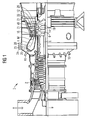
- the gas turbine 1 has a compressor 2 for combustion air, a combustion chamber or gas turbine combustor 4 and a turbine 6 for driving the compressor 2 and a generator, not shown, or a working machine.
- the turbine 6 and the compressor 2 are arranged on a common, also called turbine rotor turbine shaft 8, with the generator or the Working machine is connected, and which is rotatably mounted about its central axis 9.
- the combustion chamber 4 is equipped with a number of burners 10 for the combustion of a liquid or gaseous fuel. It is also provided on its inner wall or Brennschwandung 23 with interior trim elements 25.
- the turbine 6 has a number of rotatable blades 12 connected to the turbine shaft 8.
- the blades 12 are arranged in a ring on the turbine shaft 8 and thus form a number of blade rows.
- the turbine 6 comprises a number of fixed vanes 14, which are also fixed in a ring shape with the formation of rows of vanes on an inner casing 16 of the turbine 6.
- the blades 12 serve to drive the turbine shaft 8 by momentum transfer from the turbine 6 flowing through the working medium M.
- the vanes 14, however, serve to guide the flow of the working medium M between two seen in the flow direction of the working medium M consecutive blade rows or blade rings.
- a successive pair of a ring of vanes 14 or a row of vanes and a ring of blades 12 or a blade row is also referred to as a turbine stage.
- Each vane 14 has a platform 18, also referred to as a blade root 19, which is arranged to fix the respective vane 14 on the inner housing 16 of the turbine 6 as a wall element.
- the platform 18 is a thermally comparatively heavily loaded component, which forms the outer boundary of a hot gas channel for the working medium M flowing through the turbine 6.
- Each blade 12 is attached to the turbine shaft 8 in an analogous manner via a blade root 19, also referred to as a platform 18, the blade root 19 each carrying a profiled blade 20 extended along a blade axis.
- each guide ring 21 on the inner housing 16 of the turbine 6 is arranged between the spaced-apart platforms 18 of the guide vanes 14 of two adjacent rows of guide vanes.
- the outer surface of each guide ring 21 is also exposed to the hot, the turbine 6 flowing through the working medium M and spaced in the radial direction from the outer end 22 of the blade 12 opposite him through a gap.
- the guide rings 21 arranged between adjacent rows of guide blades serve in particular as cover elements which protect the inner wall 16 or other housing installation parts from thermal overload by the hot working medium M flowing through the turbine 6.
- the gas turbine 1 is designed for a comparatively high outlet temperature of the working medium M emerging from the combustion chamber 4 from about 1200 ° C. to 1300 ° C.
- the combustion chamber wall 23 is internally cooled.
- combustion air flows in countercurrent to the working medium M, i. the combustion gases, between the combustion chamber wall 23 and attached thereto, the combustion chamber interior 24 surrounding inner lining elements 25 through a Wandungskühlraum 26 to the burners 10.
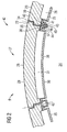
- FIG. 2 shows a fragmentary cross-section of the combustion chamber wall 23 with a manhole 27, in which a manhole cover 28 is inserted.
- the manhole cover 28 has an upper cover part 29, which is formed comparable to the Brennschdung 23, and a cover inner panel 30. Between the upper cover part 29 and the inner cover 30, which are also referred to as Deckeleinzelmaschine, an internal cooling chamber 31 of the manhole cover 27 is included. In a similar way is between the combustion chamber wall 23 and an inner lining element 25 fastened to the latter are enclosed in a wall cooling space 26.
- the internal cooling space 31 of the manhole cover 27 is connected to the wall cooling space 26 of the combustion chamber wall 23 such that the combustion air can flow unhindered, perpendicular to the plane shown.
- the upper cover part 29 has at its edge a projection 33, with which this can be inserted into a corresponding retaining recess 34 of the combustion chamber wall 23.
- the manhole cover 28 has an overall rectangular basic shape.
- the top cover 29 and the combustion chamber wall 23 are in the region of the connection between these two components, i. formed thickened in the region of the projection 33 and the retaining recess 34 to increase the stability to the combustion chamber interior 24.
- this has a contact surface 36 on which the inner cover edge 30 rests with an inner lining edge 37.
- the inner lining edge 37 is, following an inner lining main surface 38, formed integrally with this and bent from this.
- a trim edge 41 of the inner lining element 25 is on a contact surface 39 of a reinforced or thickened portion 40 of the combustion chamber wall 23 a trim edge 41 of the inner lining element 25 at.
- the manhole cover 28 is supported to the combustion chamber outside 42 through a fastening device, not shown. Both the inner cover cladding 30 and the inner cladding element 25 are supported towards the combustion chamber interior 24 by a fastening element 43 designed as a U-rail.
- a fastening element 43 designed as a U-rail.
- the U-legs 44,45 are also referred to as sections of the fastener 43.
- the fastening elements 43 are held by screws 46 which engage in the reinforced area 40 of the combustion chamber wall 23.
- the screws 46 are screwed from the combustion chamber interior 24 into the combustion chamber wall 23. An additional attachment of the inner lining element 31 on the reinforced area 40 is not required.
- the U-shaped fastener 43 held by the screws 46 on the combustion chamber wall 23 is sufficient to both hold the inner lining element 25 against the combustion chamber wall 23 and to support the inner cover 30 to the combustion chamber interior 24.
- the coatings 25, 30, which are also referred to as liners, are sealed by the fastening element 43.
- An escape of cooling air in the region of the fastening element 43 is excluded. As far as cooling air would escape from the wall cooling space 26 or the inner cooling chamber 31 on the inner lining edge 37 or on the trim edge 41, this leaked cooling air would be prevented by the U-shaped fastening element 43 from flowing into the combustion chamber interior 24. In contrast, this retained by the U-shaped fastening element 43 cooling air flow unhindered along the trained as a rail fastener 43 to the burners 10.
Landscapes
- Engineering & Computer Science (AREA)
- Chemical & Material Sciences (AREA)
- Combustion & Propulsion (AREA)
- Mechanical Engineering (AREA)
- General Engineering & Computer Science (AREA)
- Incineration Of Waste (AREA)
- Turbine Rotor Nozzle Sealing (AREA)
- Heat-Exchange Devices With Radiators And Conduit Assemblies (AREA)
- Air Supply (AREA)
Abstract
Description
- Die Erfindung betrifft eine Gasturbinenbrennkammer mit einem durch einen Mannlochdeckel verschließbaren Mannloch als Zugang zu einem Brennkammerinnenraum.
- Gasturbinen werden in vielen Bereichen zum Antrieb von Generatoren oder von Arbeitsmaschinen eingesetzt. Dabei wird der Energieinhalt eines Brennstoffs zur Erzeugung einer Rotationsbewegung einer Turbinenwelle genutzt. Der Brennstoff wird dazu in einer Brennkammer verbrannt, wobei von einem Luftverdichter verdichtete Luft zugeführt wird. Das in der Brennkammer durch die Verbrennung des Brennstoffs erzeugte, unter hohem Druck und unter hoher Temperatur stehende Arbeitsmedium wird dabei über eine der Brennkammer nachgeschaltete Turbineneinheit geführt, wo es sich arbeitsleistend entspannt.
- Bei der Auslegung derartiger Gasturbinen ist zusätzlich zur erreichbaren Leistung üblicherweise ein besonders hoher Wirkungsgrad ein Auslegungsziel. Eine Erhöhung des Wirkungsgrades lässt sich dabei aus thermodynamischen Gründen grundsätzlich durch eine Erhöhung der Austrittstemperatur erreichen, mit der das Arbeitsmedium aus der Brennkammer ab- und in die Turbineneinheit einströmt. Daher werden Temperaturen von etwa 1200 °C bis 1300 °C für derartige Gasturbinen angestrebt und auch erreicht.
- Eine im Betrieb der Gasturbine diesen Temperaturen ausgesetzte Brennkammer sollte, beispielsweise zu Inspektionszwecken, von innen zugänglich sein. Aus der
DE 199 24 607 A1 ist eine Gasturbine mit einer Brennkammer bekannt, die zumindest einen Teilbereich aufweist, der über einen Mannlochzugang prüfbar ist. Aus derDE 198 09 568 A1 ist eine Gasturbine mit einer Ringbrennkammer bekannt, wobei ein Zugang (Mannloch) in den Flammraum vorgesehen ist, durch den eine Person in den Flammraum gelangen kann. Häufig wird jedoch, insbesondere bei Gasturbinen mit hohen Verbrennungstemperaturen von 1.200°C bis 1.300°C, auf ein Mannloch in der Brennkammer verzichtet, da dieses den dort herrschenden thermischen Belastungen nicht standhalten würde oder zumindest die Dichtheit der Brennkammer nicht gewährleisten könnte. Dies gilt insbesondere für mit Brennkammerinnenverkleidungen, so genannten Linern, ausgerüstete Brennkammern. Um einen Einstieg einer Person in die Brennkammer zu ermöglichen sind daher äußerst aufwändige Demontagearbeiten erforderlich. - Der Erfindung liegt die Aufgabe zugrunde, eine Gasturbinenbrennkammer anzugeben, die für eine Gasturbine mit besonders hoher Verbrennungstemperatur geeignet ist und einen einfachen Einstieg einer Person ermöglicht.
- Diese Aufgabe wird erfindungsgemäß gelöst durch eine Gasturbinenbrennkammer mit den Merkmalen des Anspruches 1. Dabei weist die Gasturbinenbrennkammer ein Mannloch als Zugang zu einem Brennkammerinnenraum auf, welches mit einem Mannlochdeckel verschließbar ist, wobei dieser einen Innenkühlraum aufweist. Der Innenkühlraum, d.h. der Kühlraum innerhalb des Mannlochdeckels, ermöglicht eine gezielte Kühlung des den Brennkammerinnenraum abschließenden Mannlochdeckels. Der Mannlochdeckel ist daher auch unter hohen thermischen Belastungen im Brennkammerinnenraum nutzbar, ohne sich in unzulässigem Ausmaß zu verformen. Ein dichter Verschluss des Brennkammerinnenraums durch den Mannlochdeckel ist in allen Betriebszuständen gewährleistet.
- Vorzugsweise ist zusätzlich zum Mannlochdeckel auch die Brennkammerwandung, zumindest in einem thermisch besonders hoch belasteten Bereich der Gasturbinenbrennkammer, innenkühlbar. Die Brennkammerwandung weist hierbei einen so genannten Wandungskühlraum auf. Vorzugsweise ist der Innenkühlraum des Mannlochdeckels strömungstechnisch, beispielsweise mittels Verbindungsleitungen, mit dem Wandungskühlraum der Brennkammerwandung verbindbar. Damit sind auf einfache Weise an den verschiedenen Bauteilen, die den Brennkammerinnenraum einschließen, insbesondere dem Mannlochdeckel sowie der diesen umgebenden Brennkammerwandung, zumindest ähnliche thermische Bedingungen herstellbar.
- Eine strömungstechnische Verbindung zwischen dem Innenkühlraum des Mannlochdeckels und dem Wandungskühlraum der Brennkammerwandung ist nach einer bevorzugten Ausgestaltung auf besonders einfache Weise direkt durch Einsetzen des Mannlochdeckels in das Mannloch herstellbar. Damit ist insbesondere erreichbar, dass der Wandungskühlraum der Brennkammerwandung ohne Querschnittsminderung in den Innenkühlraum des Mannlochdeckels übergeht. Vorzugsweise bildet die gesamte Wandung der Gasturbinenbrennkammer einschließlich Mannlochdeckel einen homogenen Kühlraum.
- Nach einer bevorzugten Ausgestaltung ist der Mannlochdeckel oder zumindest ein Deckeleinzelteil des Mannlochdeckels, beispielsweise eine Deckelinnenverkleidung, die den Innenkühlraum des Mannlochdeckels zum Brennkammerinnenraum hin abschließt, durch ein Befestigungselement zum Brennkammerinnenraum hin abgestützt, wobei dieses Befestigungselement zugleich ein dem Mannlochdeckel benachbartes Innenverkleidungselement an der Brennkammerwandung hält. Durch diese Mehrfachfunktion des Befestigungselementes ist eine Minimierung der Anzahl an Befestigungselementen in der Brennkammer ermöglicht.
- Das Befestigungselement ist im Querschnitt bevorzugt zumindest im Wesentlichen U-förmig ausgebildet, wobei ein erster U-Schenkel das Deckeleinzelteil des Mannlochdeckels abstützt und ein zweiter U-Schenkel das Innenverkleidungselement an der Brennkammerwandung hält. Das gesamte Befestigungselement weist vorzugsweise die Form einer Schiene auf. Durch die Ausbildung des Befestigungselementes als U-Schiene weist dieses sowohl eine ausreichende Stabilität als auch Elastizität auf.
- Das Befestigungselement ist bevorzugt derart an der Brennkammerwandung gehalten, dass ein Teilstück, insbesondere ein U-Schenkel, des Befestigungselementes in das Mannloch ragt und dort die Deckelinnenverkleidung des Mannlochdeckels zum Brennkammerinnenraum hin abstützt, und - ohne Lösung des Befestigungselementes - der Mannlochdeckel vom Mannloch abnehmbar ist. Dies hat den Vorteil, dass sämtliche Befestigungselemente, die sowohl die Innenverkleidungselemente als auch die Deckelinnenverkleidung an der Brennkammerwandung bzw. dem Mannlochdeckel halten, nur einmalig befestigt werden müssen und ein Einstieg in die Gasturbinenbrennkammer durch das Mannloch ohne Entfernung eines dieser Befestigungselemente möglich ist.
- Der Vorteil der Erfindung liegt insbesondere darin, dass der Mannlochdeckel aufgrund eines Innenkühlraums hohen thermischen Belastungen standhält, wobei ein sehr einfaches Abnehmen des Mannlochdeckels einschließlich dessen Innenkühlraums vom Mannloch ermöglicht ist.
- Nachfolgend wird ein Ausführungsbeispiel der Erfindung anhand einer Zeichnung näher erläutert. Darin zeigen:
- FIG 1
- einen Halbschnitt durch eine Gasturbine,
- FIG 2
- ausschnittsweise im Querschnitt die Gasturbinenbrennkammer der Gasturbine nach
FIG 1 . - Gleiche Teile sind in beiden Figuren mit den selben Bezugszeichen versehen.
- Die Gasturbine 1 gemäß
FIG 1 weist einen Verdichter 2 für Verbrennungsluft, eine Brennkammer oder Gasturbinenbrennkammer 4 sowie eine Turbine 6 zum Antrieb des Verdichters 2 und eines nicht dargestellten Generators oder einer Arbeitsmaschine auf. Dazu sind die Turbine 6 und der Verdichter 2 auf einer gemeinsamen, auch als Turbinenläufer bezeichneten Turbinenwelle 8 angeordnet, mit der auch der Generator bzw. die Arbeitsmaschine verbunden ist, und die um ihre Mittelachse 9 drehbar gelagert ist. - Die Brennkammer 4 ist mit einer Anzahl von Brennern 10 zur Verbrennung eines flüssigen oder gasförmigen Brennstoffs bestückt. Sie ist weiterhin an ihrer Innenwand oder Brennkammerwandung 23 mit Innenverkleidungselementen 25 versehen.
- Die Turbine 6 weist eine Anzahl von mit der Turbinenwelle 8 verbundenen, rotierbaren Laufschaufeln 12 auf. Die Laufschaufeln 12 sind kranzförmig an der Turbinenwelle 8 angeordnet und bilden somit eine Anzahl von Laufschaufelreihen. Weiterhin umfaßt die Turbine 6 eine Anzahl von feststehenden Leitschaufeln 14, die ebenfalls kranzförmig unter der Bildung von Leitschaufelreihen an einem Innengehäuse 16 der Turbine 6 befestigt sind. Die Laufschaufeln 12 dienen dabei zum Antrieb der Turbinenwelle 8 durch Impulsübertrag vom die Turbine 6 durchströmenden Arbeitsmedium M. Die Leitschaufeln 14 dienen hingegen zur Strömungsführung des Arbeitsmediums M zwischen jeweils zwei in Strömungsrichtung des Arbeitsmediums M gesehen aufeinander folgenden Laufschaufelreihen oder Laufschaufelkränzen. Ein aufeinander folgendes Paar aus einem Kranz von Leitschaufeln 14 oder einer Leitschaufelreihe und aus einem Kranz von Laufschaufeln 12 oder einer Laufschaufelreihe wird dabei auch als Turbinenstufe bezeichnet.
- Jede Leitschaufel 14 weist eine auch als Schaufelfuß 19 bezeichnete Plattform 18 auf, die zur Fixierung der jeweiligen Leitschaufel 14 am Innengehäuse 16 der Turbine 6 als Wandelement angeordnet ist. Die Plattform 18 ist dabei ein thermisch vergleichsweise stark belastetes Bauteil, das die äußere Begrenzung eines Heißgaskanals für das die Turbine 6 durchströmende Arbeitsmedium M bildet. Jede Laufschaufel 12 ist in analoger Weise über einen auch als Plattform 18 bezeichneten Schaufelfuß 19 an der Turbinenwelle 8 befestigt, wobei der Schaufelfuß 19 jeweils ein entlang einer Schaufelachse erstrecktes profiliertes Schaufelblatt 20 trägt.
- Zwischen den beabstandet voneinander angeordneten Plattformen 18 der Leitschaufeln 14 zweier benachbarter Leitschaufelreihen ist jeweils ein Führungsring 21 am Innengehäuse 16 der Turbine 6 angeordnet. Die äußere Oberfläche jedes Führungsrings 21 ist dabei ebenfalls dem heißen, die Turbine 6 durchströmenden Arbeitsmedium M ausgesetzt und in radialer Richtung vom äußeren Ende 22 der ihm gegenüber liegenden Laufschaufel 12 durch einen Spalt beabstandet. Die zwischen benachbarten Leitschaufelreihen angeordneten Führungsringe 21 dienen dabei insbesondere als Abdeckelemente, die die Innenwand 16 oder andere Gehäuse-Einbauteile vor einer thermischen Überbeanspruchung durch das die Turbine 6 durchströmende heiße Arbeitsmedium M schützt.
- Zur Erzielung eines vergleichsweise hohen Wirkungsgrades ist die Gasturbine 1 für eine vergleichsweise hohe Austrittstemperatur des aus der Brennkammer 4 austretenden Arbeitsmediums M von etwa 1200 °C bis 1300 °C ausgelegt. Um dies zu ermöglichen, ist die Brennkammerwandung 23 innengekühlt. Hierbei strömt Verbrennungluft im Gegenstrom zum Arbeitsmedium M, d.h. den Verbrennungsgasen, zwischen der Brennkammerwandung 23 und den an dieser befestigten, den Brennkammerinnenraum 24 umgebenden Innenverkleidungselementen 25 durch einen Wandungskühlraum 26 zu den Brennern 10. Durch diese Brennraumkühlung wird gleichzeitig in gewollter Weise die Verbrennungsluft erhitzt.
- Die
FIG 2 zeigt ausschnittsweise im Querschnitt die Brennkammerwandung 23 mit einem Mannloch 27, in welches ein Mannlochdeckel 28 eingesetzt ist. Der Mannlochdeckel 28 weist ein Deckeloberteil 29 auf, welches vergleichbar der Brennkammerwandung 23 ausgebildet ist, sowie eine Deckelinnenverkleidung 30. Zwischen dem Deckeloberteil 29 und der Deckelinnenverkleidung 30, welche jeweils auch als Deckeleinzelteile bezeichnet werden, ist ein Innenkühlraum 31 des Mannlochdeckels 27 eingeschlossen. In entsprechender Weise ist zwischen der Brennkammerwandung 23 und einem an dieser befestigten Innenverkleidungselement 25 ein Wandungskühlraum 26 eingeschlossen. Der Innenkühlraum 31 des Mannlochdeckels 27 ist mit dem Wandungskühlraum 26 der Brennkammerwandung 23 derart verbunden, dass die Verbrennungsluft ungehindert, senkrecht zur dargestellten Ebene, strömen kann. - Das Deckeloberteil 29 weist an dessen Rand einen Vorsprung 33 auf, mit dem dieses in eine korrespondierende Haltevertiefung 34 der Brennkammerwandung 23 einsetzbar ist. Der Mannlochdeckel 28 hat insgesamt eine rechteckige Grundform. Das Deckeloberteil 29 sowie die Brennkammerwandung 23 sind im Bereich der Verbindung zwischen diesen beiden Bauteilen, d.h. im Bereich des Vorsprungs 33 bzw. der Haltevertiefung 34 zur Erhöhung der Stabilität zum Brennkammerinnenraum 24 hin verdickt ausgebildet. Im verdickten oder verstärkten Bereich 35 des Deckeloberteils 28 weist dieses eine Anlagefläche 36 auf, auf welcher die Deckelinnenverkleidung 30 mit einem Innenverkleidungsrand 37 aufliegt. Der Innenverkleidungsrand 37 ist, anschließend an eine Innenverkleidungshauptfläche 38, einstückig mit dieser und von dieser aus abgekröpft ausgebildet. In analoger Weise liegt an einer Anlagefläche 39 eines verstärkten oder verdickten Bereiches 40 der Brennkammerwandung 23 ein Verkleidungsrand 41 des Innenverkleidungselementes 25 an.
- Der Mannlochdeckel 28 wird zur Brennkammeraußenseite 42 hin durch eine nicht dargestellte Befestigungsvorrichtung abgestützt. Sowohl die Deckelinnenverkleidung 30 als auch das Innenverkleidungselement 25 werden zum Brennkammerinnenraum 24 hin durch ein als U-Schiene ausgebildetes Befestigungselement 43 abgestützt. Hierbei liegt ein erster U-Schenkel 44 am Innenverkleidungsrand 37 des Mannlochdeckels 27 und ein zweiter U-Schenkel 45 am Verkleidungsrand 41 des Innenverkleidungselementes 31 an. Die U-Schenkel 44,45 werden auch als Teilstücke des Befestigungselementes 43 bezeichnet. Zur Abstützung des Mannlochdeckels 27 zum Brennkammerinnenraum 24 hin sind damit insgesamt lediglich zwei Befestigungselemente 43 erforderlich. Die Befestigungselemente 43 sind mit Schrauben 46, welche in den verstärkten Bereich 40 der Brennkammerwandung 23 eingreifen, an dieser gehalten.
- Die Schrauben 46 sind vom Brennkammerinnenraum 24 aus in die Brennkammerwandung 23 eingeschraubt. Eine zusätzliche Befestigung des Innenverkleidungselementes 31 am verstärkten Bereich 40 ist nicht erforderlich. Das mit den Schrauben 46 an der Brennkammerwandung 23 gehaltene U-förmige Befestigungselement 43 ist ausreichend, um sowohl das Innenverkleidungselement 25 an der Brennkammerwand 23 zu halten als auch die Deckelinnenverkleidung 30 zum Brennkammerinnenraum 24 hin abzustützen. Die auch als Liner bezeichneten Verkleidungen 25,30 sind durch das Befestigungselement 43 abgedichtet. Ein Entweichen von Kühlluft im Bereich des Befestigungselementes 43 ist ausgeschlossen. Soweit am Innenverkleidungsrand 37 oder am Verkleidungsrand 41 Kühlluft aus dem Wandungskühlraum 26 beziehungsweise dem Innenkühlraum 31 austreten würde, würde diese ausgetretene Kühlluft durch das U-förmige Befestigungselement 43 gehindert, in den Brennkammerinnenraum 24 einzuströmen. Dagegen kann diese durch das U-förmige Befestigungselement 43 zurückgehaltene Kühlluft ungehindert längs des als Schiene ausgebildeten Befestigungselementes 43 zu den Brennern 10 strömen.
- Ein Entfernen des Befestigungselementes 43 oder ein Lösen der Schrauben 46 ist zur Entfernung des Mannlochdeckels 27 vom Mannloch 27 nicht erforderlich. Dies ist ermöglicht durch die Verhakungskonfiguration, mit der die Befestigungselemente 43 die Innenverkleidungselemente 25 sowie die Deckelinnenverkleidung 30 zum Brennkammerinnenraum 24 hin abstützen. Das Befestigungselement 43 überbrückt bei mit dem Mannlochdeckel 28 verschlossener Brennkammer 4 den Zwischenraum zwischen dem Innenverkleidungsrand 37 des Mannlochdeckels 27 und dem Verkleidungsrand 41 des Innenverkleidungselementes 31, so dass das heiße Arbeitsmedium M nicht vom Brennkammerinnenraum 24 aus an die Brennkammerwandung 23 oder das Deckeloberteil 29 gelangt. Die Brennkammer 4 ist damit einschließlich des Mannlochdeckels 28 vollständig innenverkleidet.
Claims (7)
- Gasturbinenbrennkammer (4) mit einem durch einen Mannlochdeckel (28) verschließbaren Mannloch (27) als Zugang zu einem Brennkammerinnenraum (24) und einem Mannlochdeckel zum Verschliessen des Mannlochs, gekennzeichnet durch einen innerhalb des Mannlochdeckels (28) angeordneten Kühlraum (31).
- Gasturbinenbrennkammer (4) nach Anspruch 1, gekennzeichnet durch einen Wandungskühlraum (26) einer Brennkammerwandung (23).
- Gasturbinenbrennkammer (4) nach Anspruch 2, dadurch gekennzeichnet, dass der Innenkühlraum (31) des Mannlochdeckels (28) strömungstechnisch mit dem Wandungskühlraum (26) der Brennkammerwandung (23) verbindbar ist.
- Gasturbinenbrennkammer (4) nach Anspruch 3, dadurch gekennzeichnet, dass der Innenkühlraum (31) des Mannlochdeckels (28) durch Einsetzen des Mannlochdeckels (28) in das Mannloch (27) direkt mit dem Wandungskühlraum (26) der Brennkammerwandung (23) verbindbar ist.
- Gasturbinenbrennkammer (4) nach einem der Ansprüche 2 bis 4, gekennzeichnet durch ein Befestigungselement (43), welches zumindest ein Deckeleinzelteil (29,30) des Mannlochdeckels (28) zum Brennkammerinnenraum (24) hin abstützt und zugleich ein dem Mannlochdeckel (28) benachbartes Innenverkleidungselement (25) an der Brennkammerwandung (23) hält.
- Gasturbinenbrennkammer (4) nach Anspruch 5, dadurch gekennzeichnet , dass das Befestigungselement (43) im Querschnitt zumindest im Wesentlichen U-förmig ausgebildet ist, wobei ein erster U-Schenkel (44) das Deckeleinzelteil (29,30) abstützt und ein zweiter U-Schenkel (45) das Innenverkleidungselement (25) hält.
- Gasturbinenbrennkammer (4) nach Anspruch 5 oder 6, dadurch gekennzeichnet, dass ein Teilstück (44,45) des Befestigungselementes (43) derart in das Mannloch (27) ragt, dass eine Deckelinnenverkleidung (30) des Mannlochdeckels (28) zum Brennkammerinnenraum (24) hin abgestützt ist und der Mannlochdeckel (28) vom Mannloch (27) abnehmbar ist.
Priority Applications (1)
| Application Number | Priority Date | Filing Date | Title |
|---|---|---|---|
| EP03753347A EP1529181B1 (de) | 2002-08-16 | 2003-08-01 | Gasturbinenbrennkammer |
Applications Claiming Priority (4)
| Application Number | Priority Date | Filing Date | Title |
|---|---|---|---|
| EP02018489 | 2002-08-16 | ||
| EP02018489A EP1389714A1 (de) | 2002-08-16 | 2002-08-16 | Gasturbinenbrennkammer |
| PCT/EP2003/008548 WO2004023042A1 (de) | 2002-08-16 | 2003-08-01 | Gasturbinenbrennkammer |
| EP03753347A EP1529181B1 (de) | 2002-08-16 | 2003-08-01 | Gasturbinenbrennkammer |
Publications (2)
| Publication Number | Publication Date |
|---|---|
| EP1529181A1 EP1529181A1 (de) | 2005-05-11 |
| EP1529181B1 true EP1529181B1 (de) | 2008-04-09 |
Family
ID=30470278
Family Applications (2)
| Application Number | Title | Priority Date | Filing Date |
|---|---|---|---|
| EP02018489A Withdrawn EP1389714A1 (de) | 2002-08-16 | 2002-08-16 | Gasturbinenbrennkammer |
| EP03753347A Expired - Lifetime EP1529181B1 (de) | 2002-08-16 | 2003-08-01 | Gasturbinenbrennkammer |
Family Applications Before (1)
| Application Number | Title | Priority Date | Filing Date |
|---|---|---|---|
| EP02018489A Withdrawn EP1389714A1 (de) | 2002-08-16 | 2002-08-16 | Gasturbinenbrennkammer |
Country Status (6)
| Country | Link |
|---|---|
| US (1) | US20060037321A1 (de) |
| EP (2) | EP1389714A1 (de) |
| JP (1) | JP4167224B2 (de) |
| CN (1) | CN1318805C (de) |
| DE (1) | DE50309588D1 (de) |
| WO (1) | WO2004023042A1 (de) |
Families Citing this family (5)
| Publication number | Priority date | Publication date | Assignee | Title |
|---|---|---|---|---|
| EP1398569A1 (de) * | 2002-09-13 | 2004-03-17 | Siemens Aktiengesellschaft | Gasturbine |
| EP1862740B1 (de) * | 2006-05-31 | 2015-09-16 | Siemens Aktiengesellschaft | Brennkammerwand |
| EP2426321A1 (de) | 2010-09-03 | 2012-03-07 | Siemens Aktiengesellschaft | Gehäuse für eine Gasturbine |
| US9534783B2 (en) * | 2011-07-21 | 2017-01-03 | United Technologies Corporation | Insert adjacent to a heat shield element for a gas turbine engine combustor |
| EP3134680B1 (de) * | 2014-09-29 | 2018-07-04 | Siemens Aktiengesellschaft | Hitzeschildelement für einen hitzeschild einer brennkammer |
Family Cites Families (10)
| Publication number | Priority date | Publication date | Assignee | Title |
|---|---|---|---|---|
| GB626249A (en) * | 1946-05-23 | 1949-07-12 | Babcock & Wilcox Ltd | Improvements in or relating to closure means for openings in walls of chambers arranged to contain gas under pressure |
| US4480436A (en) * | 1972-12-19 | 1984-11-06 | General Electric Company | Combustion chamber construction |
| US3978662A (en) * | 1975-04-28 | 1976-09-07 | General Electric Company | Cooling ring construction for combustion chambers |
| US4189352A (en) * | 1975-08-14 | 1980-02-19 | Krupp-Koppers, Gmbh | Coke oven door |
| US5333443A (en) * | 1993-02-08 | 1994-08-02 | General Electric Company | Seal assembly |
| DE19502730A1 (de) * | 1995-01-28 | 1996-08-01 | Abb Management Ag | Keramische Auskleidung |
| US5782294A (en) * | 1995-12-18 | 1998-07-21 | United Technologies Corporation | Cooled liner apparatus |
| DE19809568A1 (de) | 1998-03-05 | 1999-08-19 | Siemens Ag | Ringbrennkammer, Verwendung einer Ringbrennkammer und Einsatz für eine Öffnung in einer Brennkammer |
| US6415724B1 (en) * | 1999-01-01 | 2002-07-09 | The Babcock & Wilcox Company | Water-jacketed, high-temperature, stretcher-accessible door for a boiler |
| DE19924607A1 (de) | 1999-05-28 | 2000-11-30 | Siemens Ag | Inspektionsvorrichtung für eine Ringbrennkammer einer Gasturbine und Verfahren zur Inspektion einer Ringbrennkammer einer Gasturbine |
-
2002
- 2002-08-16 EP EP02018489A patent/EP1389714A1/de not_active Withdrawn
-
2003
- 2003-08-01 WO PCT/EP2003/008548 patent/WO2004023042A1/de not_active Ceased
- 2003-08-01 US US10/524,523 patent/US20060037321A1/en not_active Abandoned
- 2003-08-01 JP JP2004533306A patent/JP4167224B2/ja not_active Expired - Fee Related
- 2003-08-01 CN CNB038188929A patent/CN1318805C/zh not_active Expired - Fee Related
- 2003-08-01 DE DE50309588T patent/DE50309588D1/de not_active Expired - Lifetime
- 2003-08-01 EP EP03753347A patent/EP1529181B1/de not_active Expired - Lifetime
Also Published As
| Publication number | Publication date |
|---|---|
| US20060037321A1 (en) | 2006-02-23 |
| CN1675502A (zh) | 2005-09-28 |
| CN1318805C (zh) | 2007-05-30 |
| WO2004023042A1 (de) | 2004-03-18 |
| EP1389714A1 (de) | 2004-02-18 |
| JP4167224B2 (ja) | 2008-10-15 |
| EP1529181A1 (de) | 2005-05-11 |
| DE50309588D1 (de) | 2008-05-21 |
| JP2005535867A (ja) | 2005-11-24 |
Similar Documents
| Publication | Publication Date | Title |
|---|---|---|
| DE69936176T2 (de) | Berstschutzring für Turbinen | |
| EP2344723B1 (de) | Gasturbine mit dichtplatten an der turbinenscheibe | |
| DE19821889B4 (de) | Verfahren und Vorrichtung zur Durchführung von Reparatur- und/oder Wartungsarbeiten im Innengehäuse einer mehrschaligen Turbomaschine | |
| EP1183444B1 (de) | Strömungsmaschine sowie dichtelement für einen rotor einer strömungsmaschine | |
| EP1413831A1 (de) | Ringbrennkammern für eine Gasturbine und Gasturbine | |
| DE112013006128T5 (de) | Laufschaufel und zugehöriges Herstellungsverfahren | |
| EP2342425B1 (de) | Gasturbine mit sicherungsplatte zwischen schaufelfuss und scheibe | |
| DE102014204481A1 (de) | Brennkammer einer Gasturbine | |
| EP2084368A1 (de) | Turbinenschaufel | |
| DE102015205975A1 (de) | Umführungs-Hitzeschildelement | |
| WO2015022222A1 (de) | Hitzeschild mit mindestens einem helmholtzresonator | |
| EP1529181B1 (de) | Gasturbinenbrennkammer | |
| EP2236759A1 (de) | Laufschaufelsystem | |
| EP1926927A1 (de) | Hochtemperaturfeste dichtungsanordnung, insbesondere für gasturbinen | |
| EP0616679B1 (de) | Kühlluftkühler für gasturbinen | |
| EP2206885A1 (de) | Gasturbine | |
| EP1904717B1 (de) | HEIßGASFÜHRENDES GEHÄUSEELEMENT, WELLENSCHUTZMANTEL UND GASTURBINENANLAGE | |
| EP1467151A1 (de) | Hitzeschildelement | |
| WO2009109430A1 (de) | Dichtungsanordnung und gasturbine | |
| CH643050A5 (de) | Gasturbinentriebwerk mit ringbrennkammer. | |
| WO2006120204A1 (de) | Brennkammerwand, gasturbinenanlage und verfahren zum an- oder abfahren einer gasturbinenanlage | |
| EP1247943A1 (de) | Formstück zur Bildung eines kühlbaren Turbinen-Mantelrings | |
| EP1429077B1 (de) | Gasturbine | |
| EP1537363A1 (de) | Gasturbine | |
| EP1422479B1 (de) | Brennkammer zur Verbrennung eines brennbaren Fluidgemisches |
Legal Events
| Date | Code | Title | Description |
|---|---|---|---|
| PUAI | Public reference made under article 153(3) epc to a published international application that has entered the european phase |
Free format text: ORIGINAL CODE: 0009012 |
|
| 17P | Request for examination filed |
Effective date: 20050120 |
|
| AK | Designated contracting states |
Kind code of ref document: A1 Designated state(s): AT BE BG CH CY CZ DE DK EE ES FI FR GB GR HU IE IT LI LU MC NL PT RO SE SI SK TR |
|
| RBV | Designated contracting states (corrected) |
Designated state(s): CH DE FR GB IT LI |
|
| GRAP | Despatch of communication of intention to grant a patent |
Free format text: ORIGINAL CODE: EPIDOSNIGR1 |
|
| GRAS | Grant fee paid |
Free format text: ORIGINAL CODE: EPIDOSNIGR3 |
|
| GRAA | (expected) grant |
Free format text: ORIGINAL CODE: 0009210 |
|
| AK | Designated contracting states |
Kind code of ref document: B1 Designated state(s): CH DE FR GB IT LI |
|
| REG | Reference to a national code |
Ref country code: GB Ref legal event code: FG4D Free format text: NOT ENGLISH |
|
| REG | Reference to a national code |
Ref country code: CH Ref legal event code: NV Representative=s name: SIEMENS SCHWEIZ AG Ref country code: CH Ref legal event code: EP |
|
| GBT | Gb: translation of ep patent filed (gb section 77(6)(a)/1977) |
Effective date: 20080415 |
|
| REF | Corresponds to: |
Ref document number: 50309588 Country of ref document: DE Date of ref document: 20080521 Kind code of ref document: P |
|
| ET | Fr: translation filed | ||
| PLBE | No opposition filed within time limit |
Free format text: ORIGINAL CODE: 0009261 |
|
| STAA | Information on the status of an ep patent application or granted ep patent |
Free format text: STATUS: NO OPPOSITION FILED WITHIN TIME LIMIT |
|
| 26N | No opposition filed |
Effective date: 20090112 |
|
| REG | Reference to a national code |
Ref country code: CH Ref legal event code: PCAR Free format text: SIEMENS SCHWEIZ AG;INTELLECTUAL PROPERTY FREILAGERSTRASSE 40;8047 ZUERICH (CH) |
|
| REG | Reference to a national code |
Ref country code: FR Ref legal event code: PLFP Year of fee payment: 13 |
|
| PGFP | Annual fee paid to national office [announced via postgrant information from national office to epo] |
Ref country code: GB Payment date: 20150812 Year of fee payment: 13 |
|
| PGFP | Annual fee paid to national office [announced via postgrant information from national office to epo] |
Ref country code: FR Payment date: 20150818 Year of fee payment: 13 |
|
| PGFP | Annual fee paid to national office [announced via postgrant information from national office to epo] |
Ref country code: IT Payment date: 20150825 Year of fee payment: 13 |
|
| PGFP | Annual fee paid to national office [announced via postgrant information from national office to epo] |
Ref country code: CH Payment date: 20151102 Year of fee payment: 13 Ref country code: DE Payment date: 20151016 Year of fee payment: 13 |
|
| REG | Reference to a national code |
Ref country code: DE Ref legal event code: R119 Ref document number: 50309588 Country of ref document: DE |
|
| REG | Reference to a national code |
Ref country code: CH Ref legal event code: PL |
|
| GBPC | Gb: european patent ceased through non-payment of renewal fee |
Effective date: 20160801 |
|
| PG25 | Lapsed in a contracting state [announced via postgrant information from national office to epo] |
Ref country code: LI Free format text: LAPSE BECAUSE OF NON-PAYMENT OF DUE FEES Effective date: 20160831 Ref country code: CH Free format text: LAPSE BECAUSE OF NON-PAYMENT OF DUE FEES Effective date: 20160831 |
|
| REG | Reference to a national code |
Ref country code: FR Ref legal event code: ST Effective date: 20170428 |
|
| PG25 | Lapsed in a contracting state [announced via postgrant information from national office to epo] |
Ref country code: FR Free format text: LAPSE BECAUSE OF NON-PAYMENT OF DUE FEES Effective date: 20160831 Ref country code: GB Free format text: LAPSE BECAUSE OF NON-PAYMENT OF DUE FEES Effective date: 20160801 Ref country code: DE Free format text: LAPSE BECAUSE OF NON-PAYMENT OF DUE FEES Effective date: 20170301 |
|
| PG25 | Lapsed in a contracting state [announced via postgrant information from national office to epo] |
Ref country code: IT Free format text: LAPSE BECAUSE OF NON-PAYMENT OF DUE FEES Effective date: 20160801 |