EP1528983B1 - Dispositif pour maintenir au moins un habillage sur un cylindre d'une machine d'impression rotative et procede pour monter ce dispositif - Google Patents
Dispositif pour maintenir au moins un habillage sur un cylindre d'une machine d'impression rotative et procede pour monter ce dispositif Download PDFInfo
- Publication number
- EP1528983B1 EP1528983B1 EP03794776A EP03794776A EP1528983B1 EP 1528983 B1 EP1528983 B1 EP 1528983B1 EP 03794776 A EP03794776 A EP 03794776A EP 03794776 A EP03794776 A EP 03794776A EP 1528983 B1 EP1528983 B1 EP 1528983B1
- Authority
- EP
- European Patent Office
- Prior art keywords
- retaining means
- clamp
- channel
- spring
- limb
- Prior art date
- Legal status (The legal status is an assumption and is not a legal conclusion. Google has not performed a legal analysis and makes no representation as to the accuracy of the status listed.)
- Expired - Lifetime
Links
- 238000000034 method Methods 0.000 title claims description 10
- 238000012856 packing Methods 0.000 title claims 4
- 230000001154 acute effect Effects 0.000 claims abstract description 13
- 238000007639 printing Methods 0.000 claims abstract description 13
- 239000002184 metal Substances 0.000 claims description 3
- 238000004804 winding Methods 0.000 claims description 3
- 210000002414 leg Anatomy 0.000 description 14
- 210000000689 upper leg Anatomy 0.000 description 10
- 238000004519 manufacturing process Methods 0.000 description 7
- 238000005452 bending Methods 0.000 description 5
- 230000000284 resting effect Effects 0.000 description 3
- 238000003860 storage Methods 0.000 description 3
- 239000000725 suspension Substances 0.000 description 3
- 241000209035 Ilex Species 0.000 description 2
- 238000003780 insertion Methods 0.000 description 2
- 230000037431 insertion Effects 0.000 description 2
- 230000006978 adaptation Effects 0.000 description 1
- 230000015572 biosynthetic process Effects 0.000 description 1
- UQMRAFJOBWOFNS-UHFFFAOYSA-N butyl 2-(2,4-dichlorophenoxy)acetate Chemical compound CCCCOC(=O)COC1=CC=C(Cl)C=C1Cl UQMRAFJOBWOFNS-UHFFFAOYSA-N 0.000 description 1
- 230000000694 effects Effects 0.000 description 1
- 238000005538 encapsulation Methods 0.000 description 1
- 238000005516 engineering process Methods 0.000 description 1
- 230000002349 favourable effect Effects 0.000 description 1
- 230000003993 interaction Effects 0.000 description 1
- 239000000463 material Substances 0.000 description 1
- 239000007769 metal material Substances 0.000 description 1
- 238000004080 punching Methods 0.000 description 1
- 230000035484 reaction time Effects 0.000 description 1
- 230000001960 triggered effect Effects 0.000 description 1
Images


Classifications
-
- B—PERFORMING OPERATIONS; TRANSPORTING
- B41—PRINTING; LINING MACHINES; TYPEWRITERS; STAMPS
- B41F—PRINTING MACHINES OR PRESSES
- B41F27/00—Devices for attaching printing elements or formes to supports
- B41F27/12—Devices for attaching printing elements or formes to supports for attaching flexible printing formes
- B41F27/1262—Devices for attaching printing elements or formes to supports for attaching flexible printing formes without tensioning means
Definitions
- the invention relates to a device for holding at least one elevator on a cylinder of a rotary printing press according to the preamble of claim 1 and a method for assembling this device according to the preamble of claim 31.
- a device arranged in a channel of a cylinder of a rotary printing press for fixing an elevator to be mounted on the cylinder is known, the device having a one-armed lever and a spring and the lever having a pivot axis fixed to the cylinder, the spring between a wall of the channel and the Lever is clamped.
- the channel has an opening and the lever and the spring are arranged in a base body, wherein the base body is formed as a pipe corresponding to the cross section of the channel and wherein the lever in the region of the opening of the channel opposite wall of the base body pivotally mounted is.
- a method and a device for clamping and releasing flexible plates are known, wherein the device is enclosed in a base body arranged in a channel of a cylinder of a printing machine. Clamping elements of the device are pivotally mounted in abutments, wherein the Abutment are formed as slots in the base body, in which engage the clamping elements with its lower end. Moreover, the cross section of the channel is adapted to the cross section of the channel-shaped base body.
- the invention has for its object to provide a device for holding at least one elevator on a cylinder of a rotary printing machine, in which the high manufacturing requirements are reduced, which consist for a dimensionally accurate adaptation of the channel and base body when a base body with its entire wall the channel facing surface is fitted in the channel. Furthermore, the invention is also based on the object to provide a method for mounting this device.
- the achievable with the present invention consist in particular in that the consisting of a one-armed lever and a spring device for attaching an elevator on a cylinder of a rotary printing machine forms an easy to install in a channel of a cylinder unit, said unit is inexpensive to produce.
- the solution found has the advantage that the holding means largely comprehensive base body is not required, which already means a saving of material and thus lower costs.
- Generic devices according to the prior art show tubular base body, which are fitted as well as with their entire the wall of the channel facing surface in the channel, for dimensionally accurate adjustment of the channel and base body obviously higher manufacturing requirements than in a claim according bracket, which due to its design only has to be insertable into the channel and sufficient to fulfill its function at least three discrete support points.
- bracket attached to the holding means and not vice versa, the holding means is loosely inserted into a base body, there are advantages in the assembly of the device. It is particularly advantageous that the bracket fixes the holding means in its bearing point, whereby the holding means secured against unintentional release from its operating position and the device as a whole in the channel also is arranged simultaneously against rotation.
- additional measures are required to its rotation.
- the spring which spreads the bracket and the retaining means can be securely locked at least at one end, which likewise has a mounting advantage. The spring is guided linearly and is thus protected against lateral breakage.
- a stop provided between the bracket and the retaining means prevents the spring from being pushed to block, the spring attempting to escape laterally.
- the stop advantageously prevents the retaining means from pinching an end of the elevator suspended from the leading edge in the direction of production of the cylinder, which would be an obstacle to removal of a winding wound around the cylinder.
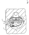
- a flexible plate-shaped printing forme 03 thereby attached that at the ends of the elevator 03 bent leg 04; 06 in a cylinder 01 arranged in the channel 07, which has a direction to the outer surface 02 of the cylinder 01 opening 11, introduced and there substantially to the mantel vomnahen walls 08; 09 of the opening 11 are applied.
- the legs 04; 06 also abut the region of the opening 11 subsequent and deeper inside the cylinder 01 lying wall 12 of the channel 07, because the boundary between the walls 08; 09 of the opening 11 and the wall 12 of the channel 07 is flowing.
- the channel 07 may have different cross-sectional geometries without a hindering effect of the invention, but is as in the Fig. 1 shown - a circular cross section manufacturing technology favorable.
- the description of the invention is here for the sake of simplicity, as if on the cylinder 01 only a single, the cylinder 01 encircling elevator 03 is to be attached.
- the elevator 03 to be fastened to the cylinder 01 has a leading end 13 and a trailing end 14, each having a bevelled leg 04; 06 on.
- the opening 11 of the channel 07 has a seen in the production direction P of the cylinder 01 front edge 16, from which a wall 08 extends to the channel 07, said wall 08 is also referred to as a first wall 08, and a rear edge 17th from which a wall 09 also extends to the channel 07, said wall 09 is called the second wall 09.
- the opening 11 is formed on the lateral surface 02 of the cylinder 01 long and narrow and thus slit-shaped, wherein the slot width S in comparison to the depth t of the channel 07, the z. B.
- the slot width S of the opening 11 tapers towards the lateral surface 02 of the cylinder 01 and it increases toward the channel 07.
- the leg 04 of the leading end 13 of the elevator 03 can be suspended at the front edge 16 of the opening 11, so that this leg 04 preferably rests positively against the wall 08 extending from the front edge 16 to the channel 08.
- the wall 09 falls at the rear edge 17 of the opening 11 in approximately perpendicular to the channel 07 down.
- the wall 09 may also be slightly inclined so that the opening 11 widens towards the channel 07.
- An angle ⁇ which is as the opening angle between the extending from the rear edge 17 to the channel 07 extending wall 09 and the already mentioned, resting on the outer surface 02 of the cylinder 01 on the opening 11 tangent T, z. B. in the range between 85 ° and 95 ° and is preferably 90 °.
- the channel 07 extends as a rule axially parallel to the cylinder 01 z. B. over its entire length.
- a recess 18 for example, a groove 18, in which or in a dimensionally stable, rigid, preferably plate-shaped holding means 19 - preferably loosely - set and pivotally mounted is.
- the holding means 19 may, for. Example, a metallic, longitudinally in the channel 07 extending, preferably be stored in or at the bottom of the channel 07 bar.
- the groove 18 is thus the bearing point and support point des.le formed as a lever holding means 19.
- the width B of the groove 18 is formed larger than the thickness D of the holding means 19.
- the holding means 19 is formed such that it has a first upper, on one of the two walls 08 or 09 of the opening 11 can be applied end 21 and an opening 11 opposite the second lower end 22, wherein this lower end 22 is supported in the groove 18.
- the groove 18 in the wall 12 of the channel 07 may be provided in the interior of the channel 07 near the wall 12, a holder in which the holding means 19 is pivotally mounted.
- the holding means 19 accordingly divides by its arrangement and design, the cross section of the channel 07 in two sections.
- bracket 23 In channel 07 is a dimensionally stable bracket 23 with one or more edges 32; 33 provided.
- the bracket 23 has two ends, wherein z. B. a first lower leg 26 is directed from a first edge 32 to one end of the bracket 23 and a second upper leg 27 from a second edge 33 to another end of the bracket 23.
- the bracket 23 is thus preferably designed as a polygonal and has a substantially semicircular, U- or L-shaped cross section, wherein the bracket 23rd in the channel 07 is preferably arranged predominantly only to one side of the holding means 19, on that side which faces the opening at the acute angle ⁇ to the channel 07 extending wall 08 of the opening 11.
- the bracket 23 is advantageously directed from the second lower end 22 of the holding means 19 to the first upper end 21, wherein in a preferred embodiment, one end of the bracket 23 to the ⁇ at the acute angle ⁇ to the channel 07 extending wall 08 of the opening 11 extends.
- the bracket 23 is z. B. formed as a punched sheet metal and bent component and may under certain circumstances have multiple bending points.
- the bracket 23 may be a dimensionally stable molded part made of plastic.
- suitable support points are formed for its storage in the channel 07, z. As sharp or rounded edges or in relation to the entire surface of the bracket 23 small, z. B. plane faces.
- the lower leg 26 of the bracket 23 is preferably attached to the lower end 22 of the holding means 19.
- the attachment of the lower leg 26 at the lower end 22 of the holding means 19 may, for. B. be carried out by the fact that at least one breakthrough, z. B. a bore or punching, in particular a T-shaped punched-out, is mounted in the at least one lower leg 26 formed on the tab 28 (FIG. FIGS. 2 and 3 ), in particular a T-shaped lug 28, can be suspended.
- a T-shaped design of the punch in the holding means 19 and the tab 28 has the advantage that a hooked to the holding means 19 tab 28 can be locked.
- bracket 23 is supported in the channel 07 at discrete, ie spaced-apart support points, preferably at three support points, with a support point on the wall 12 of the channel 07 in the opening 11 facing (upper) channel half or in particular at the ⁇ under the acute angle ⁇ to the channel 07 extending towards wall 08 of the opening 11 is located.
- the Fig. 1 shows a bracket 23 which is supported at discrete support points and thus does not abut the entire surface of the wall 12 of the channel 07.
- the bracket 23 is supported with its second upper leg 27 at the ⁇ at the acute angle to the channel 07 extending toward wall 08 of the opening 11 and with an edge 32 on the wall 12 of the channel 07 from. Further support points are given by the end faces of a arranged between the second upper leg 27 of the bracket 23 and the first upper end 21 of the holding means 19 coil spring 31 and by attaching the first lower leg 26 of the bracket 23 at the second lower end 22 of the holding means 19.
- the support point of the bracket 23 at the second lower end 22 of the holding means 19 is spaced by a distance a from the bearing and pivot point of the holding means 19, wherein the distance a is a few millimeters, preferably between 1 mm to 3 mm.
- the in the Fig. 1 shown support point of the bracket 23 with the edge 32 on the wall 12 of the channel 07 is optional, because three support points for safe storage of the bracket 23 in the channel 07 sufficient.
- the use of the support point at the at the acute angle a to the channel 07 extending toward wall 08 of the opening 11 has the advantage to fix the bracket 19, the holding means 19 in its bearing and pivot point.
- the mounting of the bracket 23 in the channel 07 is decoupled from a pivoting movement of the holding means 19.
- the preferably attached to the tab 29 spring 31 is biased and spreads the bracket 23 and the holding means 19 apart.
- the spring 31 is thus supported with its one end on the bracket 23 and with its other end on the holding means 19, preferably close to the upper end 21 of the holding means 19 so that acting as a lever holding means 19 from its bearing point in the groove 18 to Spring 31 forms as long as possible lever arm.
- the support of the spring 31 on the bracket 23 can by a or a plurality of laterally formed on the flap 29 webs 34 ( FIGS. 2 and 3 ) or a suitably trained stop-shaped collar 34 are supported.
- the bending edge 33 of the bracket 23 or its upper leg 27 are supported close to or on the wall 08 extending from the front edge 16 towards the channel 07.
- the force exerted by the spring 31 arranged between the bracket 23 and the holding means 19 both on the bracket 23 and on the retaining means 19 assists in connection with the support of the bracket 23 at the wall extending at an acute angle ⁇ to the channel 07
- the upper end 21 of the holding means 19 is pressed against the rear edge 17 of the opening 11 extending wall 09, resulting in the upper end of the opening 11 11, the fixation of the holding means 19 in its storage and pivot point in the groove 21 of the holding means 19 results in a terminal point, which serves to attach a leg 06 of an elevator 03 hinged there.
- the holding means 19, the bracket 23 and the spring 31 form a structural unit which can be mounted in a simple manner in a channel 07 of a cylinder 01 by preferably lateral insertion into the channel 07.
- a method for assembling a cylinder 01 of a rotary printing press with a device for fastening at least one elevator 03 on the cylinder 01, wherein the device is arranged in a channel 07 of the cylinder 01, is characterized essentially by the method steps that a spring 31 on an upper leg 27 of a bracket 23 is placed, that a lower leg 26 of the bracket 23 is movably attached to a lower end 22 of a holding means 19 and that the holding means 19 is inserted together with the bracket 23 and the spring 31 in the channel 07.
- an abutment 37 of one of the actuation of the holding means 19 serving adjusting means 36 are movably mounted on the holding means 19 before the holding means 19 is inserted into the channel 07.
- the holding means 19, the bracket 23 and the spring 31 form an effective device in the channel 07 for attaching a cylinder 01 on a Rotary printing machine to be mounted elevator 03.
- the adjusting means 36 counteracts the applied by the spring 31 via the holding means 19 on the wall 09, extending from the rear edge 17 of the opening 11, applied contact pressure to 36 with the holding means 19 on the wall 09 upon actuation of the actuating means if necessary, to solve the caused clamping.
- the adjusting means 36 is preferably a hose 36 extending in the longitudinal direction of the channel 07 and connected to a pressure medium, e.g. B. compressed air is acted upon and can be bordered by an abutment 37.
- the abutment 37 of this actuator 36 may, for. B.
- the abutment 37 may be formed with a formed on the abutment tab 37 in at least one breakthrough of the holding means 19, z. B. be hung in a hole or a punched. This suspension of the abutment 37 may, for. B. also in the same, correspondingly larger formed breakthrough of the holding means 19, in which the lower leg 26 of the bracket 23 is mounted, so that the tab on the abutment and the tab 28 on the lower leg 26 of the bracket 23 come to rest on each other.
- abutment 37 should remain movable transversely to the holding means 19 in order to support the abutment 37 at least upon actuation of the adjusting means 36 on the wall 12 of the channel 07 can. It may also be advantageous embodiments in which the adjusting means 36 and the abutment 37 are designed as a single component by a reversibly deformable trained hollow body such. B. a pressurizable with a pressure hose except at the holding means 19 side facing z. B.
- Adjusting means 36 may be dispensable an abutment 37 in the form described here.
- a further embodiment provides to form the abutment 37 as a bar extending in the axial direction of the channel over its entire length, wherein the abutment on the end faces of the cylinder z. B. is fixed by screwing.
- the strip is advantageously designed such that it can be threaded through the slot-shaped opening 11 in the channel 07 or can be led out of this by a rotational movement about an axis parallel to the cylinder.
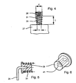
- the spring 31 which is placed on the formed on the upper leg 27 of the bracket 23 tab 29, shows the Fig. 4 .
- the spring 31 has a retracted last turn in this example, with which the spring 31 adapted to the width b of the tab 29 and by means of press fit on the tab 29 can be placed. So may the width b of the tab 29 z. B. 3 mm to 10 mm, preferably 5 mm.
- the length I of the tab 29 may, for. B. between 6 mm and 15 mm.
- a spring 31 with a retracted last turn widens with its inner diameter d over the length I of the tab 29, wherein the inner diameter d at the end, with which the spring 31 is supported on the holding means 19, z. B.
- the end face 38 of the tab 29 serves as a stop 38 for limiting a pivoting movement of the holding means 19 between the bracket 23 and the holding means 19, wherein the pivoting movement of the holding means 19 is directed to the bracket 23.
- the stop 38 prevents that between the bracket 23 and the holding means 19 arranged coil spring 31 can be pressed on block.
- a further embodiment of the arrangement of the spring 31 on the tab 29 show the FIGS. 5 and 6 .
- a sleeve 39 which preferably consists of plastic, has a bore 41 or a blind hole 41, with or with which the sleeve 39 can be attached to the tab 29.
- a sleeve 39 may also be applied directly to the suitably shaped upper leg 27 of the bracket 23.
- the spring 31 is in turn attached to the sleeve 39.
- the end face of the sleeve 39 limits the stroke of the spring 31st
- the bracket 23 in particular a dimensionally stable bracket 23 made of a metallic material, is supported for one near its one end at the ⁇ at the acute angle ⁇ to the channel 07 extending wall 08 of the opening 11 and the other with its other end on the second lower End 22 of the holding means 19 from.
- a arranged between the bracket 23 and the holding means 19 substantially parallel to the resting on the opening 11 tangent T spring 31 spreads the bracket 23 and the holding means 19 apart, whereby the spring 31 each exerts a force on the support points of the bracket 23 and for fixing the holding means 19 contributes in its bearing and pivot point in the groove 18.
- the spring 31 is preferably formed as a coil spring 31. In the Fig. 7 the coil spring 31 is shown for clarity with an interrupted winding.
- the spring 31 is mounted on a pin 43, wherein the pin 43 is preferably formed on a plate 42, wherein the plate 42 is mounted on the holding means 19 on its side remote from the bracket 23 side.
- the holding means 19 has z. B. at least one opening 44, but advantageously a plurality of openings 44, in which a mounted on the plate 42, z. B. molded pin 43 can be clipped.
- the plate 42 is secured by the clipped into the apertures 44 pin 43 on the holding means 19.
- the spring 31 is advantageously attached.
- the bracket 23 has at one end, with which it is attached to the holding means 19, advantageously a T-shaped lug 28, which is mounted in a preferably also T-shaped opening on the holding means 19.
- the actuator means 36 disposed in the channel 07 exerts a force on a channel 07 fixedly arranged, preferably cup-shaped abutment 37 and on the plate 19 attached to the holding means 42 during its actuation.
- the abutment 37 is z. B. formed as a fixed to the end faces of the cylinder 01 bar.
- a leg 27 of the bracket 23 is directed to the holding means 19.
- the end face 38 of the leg 27 forms a stop 38, against which the holding means 19 strikes at a triggered by the adjusting means 36, the bracket 23 directed pivotal movement.
Landscapes
- Engineering & Computer Science (AREA)
- Mechanical Engineering (AREA)
- Supply, Installation And Extraction Of Printed Sheets Or Plates (AREA)
- Prostheses (AREA)
- Clamps And Clips (AREA)
- Automatic Assembly (AREA)
- Rotary Presses (AREA)
Claims (33)
- Dispositif pour maintenir au moins un habillage (03) sur un cylindre (01) d'une machine d'impression rotative, le dispositif étant disposé dans un canal (07) du cylindre (01) et présentant un étrier (23), le canal (07) présentant une paroi (12) et une ouverture (11) orientée vers la surface d'enveloppe (02) du cylindre (01), au moins une paroi (08) s'étendant de l'ouverture (11) vers le canal (07), sous un angle (α) aigu par rapport à une tangente (T) reposant sur la surface d'enveloppe (02), sur l'ouverture (11), le dispositif présentant au moins un moyen de maintien (19), rigide en flexion, monté à pivotement dans le canal (07), avec une première extrémité (21) et une deuxième extrémité (22), la première extrémité (21) maintenant une branche (06), repliée, insérée dans l'ouverture (11), de l'habillage (03), et le centre de palier et de pivotement du moyen de maintien (19) se trouvant sur la deuxième extrémité (22), caractérisé en ce que l'étrier (23) disposé dans le canal (07) est réalisé avec une stabilité de forme, avec une ou plusieurs arêtes (32, 33), et est monté en palier en au moins trois emplacements d'appui discrets, l'un des au moins trois emplacements d'appui discrets de l'étrier (23) se trouvant sur un ressort (31) disposé entre l'étrier (23) et le moyen de maintien, dans la direction d'action, un autre emplacement d'appui de l'étrier (23) se trouvant sur le moyen de maintien (19), et un autre emplacement d'appui se trouvant sur la paroi (12) du canal (07) ou sur la paroi (08), s'étendant vers le canal (07) sous l'angle (α) aigu, de l'ouverture (11).
- Dispositif selon la revendication 1, caractérisé en ce que l'étrier (23) est disposé sur le moyen de maintien (19).
- Dispositif selon la revendication 1, caractérisé en ce que l'étrier (23) présente une extrémité orientée vers la première extrémité (21) du moyen de maintien (19).
- Dispositif selon la revendication 1, caractérisé en ce que l'étrier (23) s'étend à partir de la deuxième extrémité (22) du moyen de maintien (19), vers la paroi (08), s'étendant vers le canal (07) sous l'angle (α) aigu, de l'ouverture (11).
- Dispositif selon la revendication 1, caractérisé en ce que le centre de palier et de pivotement du moyen de maintien (19) est disposé dans ou sur la paroi (12) du canal (07).
- Dispositif selon la revendication 1, caractérisé en ce que l'appui, soutenu par le ressort (31), disposé entre l'étrier (23) et le moyen de maintien, grâce à un écartement entre étrier (23) et moyen de maintien (19), de l'étrier (23) fixe le moyen de maintien dans son point de tourillonnement.
- Dispositif selon la revendication 1, caractérisé en ce que le ressort (31) prend appui à proximité de la première extrémité (21) du moyen de maintien (19).
- Dispositif selon la revendication 1, caractérisé en ce qu'une butée (38) est disposée dans le canal (07), entre le moyen de maintien (19) et l'étrier (23), orienté de la deuxième extrémité (22) du moyen de maintien (19) vers sa première extrémité (21), la butée (38) limitant un mouvement de pivotement, orienté vers l'étrier (23), du moyen de maintien (19).
- Dispositif selon la revendication 1, caractérisé en ce que l'emplacement d'appui existant sur le ressort (31) se trouve à proximité de la première extrémité (21) du moyen de maintien (19).
- Dispositif selon la revendication 1, caractérisé en ce que l'emplacement d'appui se trouve sur le moyen de maintien (19), sur sa deuxième extrémité (22).
- Dispositif selon la revendication 1, caractérisé en ce que le centre de palier et de pivotement du moyen de maintien (19) est disposé à peu près diamétralement par rapport à l'ouverture (11).
- Dispositif selon la revendication 1, caractérisé en ce que le moyen de maintien (19) est une bande.
- Dispositif selon la revendication 1, caractérisé en ce que l'étrier et réalisé sous forme de pièce estampée/pliée, en tôle, ou sous forme de pièce moulée, en une matière synthétique.
- Dispositif selon la revendication 1, caractérisé en ce que, sur sa première de ses extrémités, l'étrier (23) présente une première branche (26) et, à son autre extrémité, une deuxième branche (27), la première branche (26) étant montée de manière mobile sur la deuxième extrémité (22) du moyen de maintien (19).
- Dispositif selon la revendication 14, caractérisé en ce qu'au moins une patte est réalisée sur la deuxième branche (27) de l'étrier (23), le ressort (31) étant disposé sur la patte (29), entre le moyen de maintien (19) et l'étrier (23).
- Dispositif selon la revendication 14, caractérisé en ce que la première branche (26) de l'étrier (23), ou au moins une patte (28) réalisée sur la première branche (26) de l'étrier (23),s'engage dans un passage ménagé sur le moyen de maintien (19), ou dans un perçage ou une découpure d'estampage du moyen de maintien (19).
- Dispositif selon la revendication 15, caractérisé en ce que le ressort (31) disposé sur la patte (29), sur la deuxième branche (27) de l'étrier (23), est placé, avec une liaison par ajustement de forme, avec un dernier enroulement renfoncé sur cette patte (29).
- Dispositif selon la revendication 15, caractérisé en ce que la patte (29), sur la deuxième branche (27) de l'étrier (23), présente au moins une nervure (34), formée d'un seul tenant par la matière, ou une collerette en forme de butée, réalisée de manière correspondante.
- Dispositif selon l'une des revendications 14 ou 15, caractérisé en ce qu'une douille (39) avec le ressort (31) est disposée sur la deuxième branche (27) de l'étrier (23), ou sur la patte (29) située sur la deuxième branche (27) de l'étrier (23).
- Dispositif selon la revendication 19, caractérisé en ce que la douille (39) est en matière synthétique.
- Dispositif selon la revendication 19, caractérisé en ce que la douille (39) présente un perçage (41) ou un trou borgne (41), avec lequel la douille (39) est enfichée sur la patte (29).
- Dispositif selon l'une des revendications 15 ou 19, caractérisé en ce qu'une face frontale (38) de la patte (29) ou de la douille (39) sert de butée pour la limitation de la plage de pivotement, orientée vers l'étrier (23), du moyen de maintien (19).
- Dispositif selon la revendication 1, caractérisé en ce qu'un moyen de réglage (36), servant à l'actionnement du moyen de maintien (19), est prévu dans le canal (07).
- Dispositif selon la revendication 23, caractérisé en ce que le moyen de réglage (36) présente un contre-palier (37).
- Dispositif selon la revendication 24, caractérisé en ce que le contre-palier (37) est réalisé sous forme de bande, s'étendant dans la direction axiale du canal (07), sur la totalité de sa longueur.
- Dispositif selon la revendication 25, caractérisé en ce que le contre-palier (37) est fixé sur les faces frontales du cylindre (01).
- Dispositif selon la revendication 24, caractérisé en ce que le contre-palier (37) entour au moins partiellement le moyen de réglage (36) et, sur le contre-palier (37), est formée d'un seul tenant par la matière au moins une patte, la au moins une patte s'engageant dans au moins un passage ou un perçage ou un évidement d'estampage du moyen de maintien (19).
- Dispositif selon les revendications 16 et 27, caractérisé en ce que le contre-palier (37) est introduit au même passage du moyen de maintien (19) que la première branche (26) de l'étrier (23).
- Dispositif selon la revendication 24, caractérisé en ce que le moyen de réglage (36) et le contre-palier (37) sont réalisés d'une seule pièce, en ce que le contre-palier (37) est relié, par une liaison par la matière, au moyen de réglage (36), sauf sur le côté tourné vers le moyen de maintien (19).
- Dispositif selon la revendication 1, caractérisé en ce que l'étrier (23) est désaccouplé d'un mouvement de pivotement du moyen de maintien (19).
- Procédé de montage d'un dispositif pour maintenir au moins un habillage (03) sur un cylindre (01) d'une machine d'impression rotative selon l'une des revendications précédentes, le dispositif étant disposé dans un canal (07) du cylindre (01), un ressort (31) étant disposé sur une branche (27) d'un étrier (23), avec une ou plusieurs arêtes (32, 33), une autre branche (26) de l'étrier (23) étant montée de manière mobile sur une extrémité (22), se trouvant dans ou au fond du canal (07), d'un moyen de maintien (19), et le moyen de maintien (19), conjointement avec l'étrier (23) et le ressort (31), étant introduit dans le canal (07), l'étrier (23) disposé dans le canal (07) étant monté en palier en au moins trois emplacements d'appui discrets.
- Procédé selon la revendication 31, caractérisé en ce que le dispositif est introduit latéralement dans le canal (07).
- Procédé selon la revendication 31, caractérisé en ce qu'un contre-palier (37) d'un moyen de réglage (36), servant à l'actionnement du moyen de maintien (19), est monté sur le moyen de maintien (19), avant que le moyen de maintien (19) soit introduit dans le canal (07).
Applications Claiming Priority (3)
| Application Number | Priority Date | Filing Date | Title |
|---|---|---|---|
| DE10236867A DE10236867B3 (de) | 2002-08-12 | 2002-08-12 | Vorrichtung zum Halten mindestens eines Aufzugs auf einem Zylinder einer Rotationsdruckmaschine |
| DE10236867 | 2002-08-12 | ||
| PCT/DE2003/002597 WO2004024449A1 (fr) | 2002-08-12 | 2003-08-01 | Dispositifs pour maintenir au moins un habillage sur un cylindre d'une machine d'impression rotative et procede pour monter ces dispositifs |
Publications (2)
| Publication Number | Publication Date |
|---|---|
| EP1528983A1 EP1528983A1 (fr) | 2005-05-11 |
| EP1528983B1 true EP1528983B1 (fr) | 2010-05-12 |
Family
ID=31895543
Family Applications (1)
| Application Number | Title | Priority Date | Filing Date |
|---|---|---|---|
| EP03794776A Expired - Lifetime EP1528983B1 (fr) | 2002-08-12 | 2003-08-01 | Dispositif pour maintenir au moins un habillage sur un cylindre d'une machine d'impression rotative et procede pour monter ce dispositif |
Country Status (7)
| Country | Link |
|---|---|
| US (1) | US7302889B2 (fr) |
| EP (1) | EP1528983B1 (fr) |
| AT (1) | ATE467509T1 (fr) |
| AU (1) | AU2003250805A1 (fr) |
| DE (2) | DE10236867B3 (fr) |
| ES (1) | ES2341444T3 (fr) |
| WO (1) | WO2004024449A1 (fr) |
Families Citing this family (4)
| Publication number | Priority date | Publication date | Assignee | Title |
|---|---|---|---|---|
| DE10250684B3 (de) * | 2002-10-31 | 2004-04-01 | Koenig & Bauer Ag | Verfahren zur Herstellung eines Rotationskörpers und Rotationskörper einer Druckmaschine |
| DE102006062743B4 (de) * | 2005-06-28 | 2010-10-14 | Koenig & Bauer Aktiengesellschaft | Zylinder einer Rotatiosdruckmaschine mit mindestens einem sich in Axialrichtung dieses Zylinders unter dessen Mantelfläche erstreckenden Kanal |
| DE102007028875B3 (de) * | 2007-06-22 | 2008-08-21 | Koenig & Bauer Aktiengesellschaft | Zylinder einer Rotationsdruckmaschine mit einer Vorrichtung zum Halten mindestens eines Aufzugs auf dem Zylinder |
| DE102008000061B4 (de) | 2008-01-15 | 2013-06-06 | Koenig & Bauer Aktiengesellschaft | Vorrichtung zum Halten einer Druckplatte auf einem Plattenzylinder einer Rotationsdruckmaschine |
Citations (1)
| Publication number | Priority date | Publication date | Assignee | Title |
|---|---|---|---|---|
| WO2002043962A2 (fr) * | 2000-11-28 | 2002-06-06 | Koenig & Bauer Aktiengesellschaft | Dispositif pour fixer un habillage et procede de production |
Family Cites Families (4)
| Publication number | Priority date | Publication date | Assignee | Title |
|---|---|---|---|---|
| DE3626243A1 (de) * | 1986-08-02 | 1988-02-04 | Koenig & Bauer Ag | Druckplattenbefestigungs- und spannvorrichtung |
| US5485784A (en) * | 1994-06-28 | 1996-01-23 | Walschlaeger, Sr.; Alan R. | Printing plate cylinder with universal lockup apparatus |
| FR2727350B1 (fr) * | 1994-11-24 | 1997-02-14 | Heidelberg Harris Sa | Dispositif de fixation d'une forme d'impression souple |
| DE19924787B4 (de) * | 1999-05-29 | 2004-11-04 | Koenig & Bauer Ag | Vorrichtung zum Befestigen biegsamer Platten |
-
2002
- 2002-08-12 DE DE10236867A patent/DE10236867B3/de not_active Expired - Fee Related
-
2003
- 2003-08-01 AU AU2003250805A patent/AU2003250805A1/en not_active Abandoned
- 2003-08-01 EP EP03794776A patent/EP1528983B1/fr not_active Expired - Lifetime
- 2003-08-01 US US10/523,989 patent/US7302889B2/en not_active Expired - Fee Related
- 2003-08-01 AT AT03794776T patent/ATE467509T1/de active
- 2003-08-01 WO PCT/DE2003/002597 patent/WO2004024449A1/fr not_active Application Discontinuation
- 2003-08-01 DE DE50312710T patent/DE50312710D1/de not_active Expired - Lifetime
- 2003-08-01 ES ES03794776T patent/ES2341444T3/es not_active Expired - Lifetime
Patent Citations (1)
| Publication number | Priority date | Publication date | Assignee | Title |
|---|---|---|---|---|
| WO2002043962A2 (fr) * | 2000-11-28 | 2002-06-06 | Koenig & Bauer Aktiengesellschaft | Dispositif pour fixer un habillage et procede de production |
Also Published As
| Publication number | Publication date |
|---|---|
| ATE467509T1 (de) | 2010-05-15 |
| WO2004024449A1 (fr) | 2004-03-25 |
| DE50312710D1 (de) | 2010-06-24 |
| AU2003250805A1 (en) | 2004-04-30 |
| US20060005723A1 (en) | 2006-01-12 |
| DE10236867B3 (de) | 2004-03-25 |
| EP1528983A1 (fr) | 2005-05-11 |
| US7302889B2 (en) | 2007-12-04 |
| ES2341444T3 (es) | 2010-06-21 |
Similar Documents
| Publication | Publication Date | Title |
|---|---|---|
| DE10032010C1 (de) | Anschlußarmatur mit elastischem Ring als Anschlag | |
| DE3138445A1 (de) | Federklemme, insbesondere zur befestigung von schmutzfaengern an kraftfahrzeugen | |
| EP1340617B1 (fr) | Dispositif de fixation d'une plaque d'impression flexible | |
| DE102006062743B4 (de) | Zylinder einer Rotatiosdruckmaschine mit mindestens einem sich in Axialrichtung dieses Zylinders unter dessen Mantelfläche erstreckenden Kanal | |
| EP0967701A2 (fr) | Dispositif de connexion avec protubérance de fixation divisée par des fentes au niveau des supports | |
| DE3917392C2 (fr) | ||
| DE102007047892B4 (de) | Zylinder einer Druckmaschine mit mindestens einem unter dessen Mantelfläche in dessen Axialrichtung verlaufenden Kanal | |
| EP1278634B1 (fr) | Procede pour fixer une plaque flexible | |
| EP1528983B1 (fr) | Dispositif pour maintenir au moins un habillage sur un cylindre d'une machine d'impression rotative et procede pour monter ce dispositif | |
| DE10261954B4 (de) | Zylinder einer Rotationsdruckmaschine | |
| CH656189A5 (de) | Zusammenklappbare verbindungsmuffe zum loesbaren befestigen des endes eines ersten stabes an einem zweiten stab. | |
| DE2230309B2 (de) | Befestigungsklammer für Leisten mit T-fSrmiger Aussparung und Verfahren zu ihrer Anbringung | |
| DE10220548B4 (de) | Befestigung eines biegsamen Aufzugs auf einem Zylinder einer Rotationsdruckmaschine | |
| DE10220546B4 (de) | Vorrichtung zum Befestigen von mindestens einem biegsamen Aufzug mit mindestens einem abgekanteten Schenkel auf einer Mantelfläche eines Zylinders einer Rotationsdruckmaschine | |
| DE10024087C2 (de) | Vorrichtung zum Befestigen einer Druckplatte auf einem Zylinder einer Rotationsdruckmaschine | |
| DE10218475B4 (de) | Zylinder einer Rotationsdruckmaschine mit einem Aufzug | |
| CH414278A (de) | Aufhängevorrichtung für Rohre | |
| EP0935077A1 (fr) | Console à fixer dans un trou et à douille fendue plusieurs fois |
Legal Events
| Date | Code | Title | Description |
|---|---|---|---|
| PUAI | Public reference made under article 153(3) epc to a published international application that has entered the european phase |
Free format text: ORIGINAL CODE: 0009012 |
|
| 17P | Request for examination filed |
Effective date: 20041110 |
|
| AK | Designated contracting states |
Kind code of ref document: A1 Designated state(s): AT BE BG CH CY CZ DE DK EE ES FI FR GB GR HU IE IT LI LU MC NL PT RO SE SI SK TR |
|
| AX | Request for extension of the european patent |
Extension state: AL LT LV MK |
|
| DAX | Request for extension of the european patent (deleted) | ||
| 17Q | First examination report despatched |
Effective date: 20090721 |
|
| GRAP | Despatch of communication of intention to grant a patent |
Free format text: ORIGINAL CODE: EPIDOSNIGR1 |
|
| RTI1 | Title (correction) |
Free format text: DEVICE FOR MAINTAINING AT LEAST ONE PACKING ON A CYLINDER OF A ROTARY PRESS AND METHOD FOR MOUNTING SAID DEVICE |
|
| GRAS | Grant fee paid |
Free format text: ORIGINAL CODE: EPIDOSNIGR3 |
|
| GRAA | (expected) grant |
Free format text: ORIGINAL CODE: 0009210 |
|
| RIN1 | Information on inventor provided before grant (corrected) |
Inventor name: SCHAEFER, KARL, ROBERT |
|
| AK | Designated contracting states |
Kind code of ref document: B1 Designated state(s): AT BE BG CH CY CZ DE DK EE ES FI FR GB GR HU IE IT LI LU MC NL PT RO SE SI SK TR |
|
| REG | Reference to a national code |
Ref country code: GB Ref legal event code: FG4D Free format text: NOT ENGLISH |
|
| REG | Reference to a national code |
Ref country code: CH Ref legal event code: EP |
|
| REG | Reference to a national code |
Ref country code: ES Ref legal event code: FG2A Ref document number: 2341444 Country of ref document: ES Kind code of ref document: T3 |
|
| REG | Reference to a national code |
Ref country code: IE Ref legal event code: FG4D Free format text: LANGUAGE OF EP DOCUMENT: GERMAN |
|
| REF | Corresponds to: |
Ref document number: 50312710 Country of ref document: DE Date of ref document: 20100624 Kind code of ref document: P |
|
| REG | Reference to a national code |
Ref country code: SE Ref legal event code: TRGR |
|
| REG | Reference to a national code |
Ref country code: NL Ref legal event code: VDEP Effective date: 20100512 |
|
| PG25 | Lapsed in a contracting state [announced via postgrant information from national office to epo] |
Ref country code: NL Free format text: LAPSE BECAUSE OF FAILURE TO SUBMIT A TRANSLATION OF THE DESCRIPTION OR TO PAY THE FEE WITHIN THE PRESCRIBED TIME-LIMIT Effective date: 20100512 |
|
| PG25 | Lapsed in a contracting state [announced via postgrant information from national office to epo] |
Ref country code: SI Free format text: LAPSE BECAUSE OF FAILURE TO SUBMIT A TRANSLATION OF THE DESCRIPTION OR TO PAY THE FEE WITHIN THE PRESCRIBED TIME-LIMIT Effective date: 20100512 Ref country code: FI Free format text: LAPSE BECAUSE OF FAILURE TO SUBMIT A TRANSLATION OF THE DESCRIPTION OR TO PAY THE FEE WITHIN THE PRESCRIBED TIME-LIMIT Effective date: 20100512 |
|
| REG | Reference to a national code |
Ref country code: IE Ref legal event code: FD4D |
|
| PG25 | Lapsed in a contracting state [announced via postgrant information from national office to epo] |
Ref country code: GR Free format text: LAPSE BECAUSE OF FAILURE TO SUBMIT A TRANSLATION OF THE DESCRIPTION OR TO PAY THE FEE WITHIN THE PRESCRIBED TIME-LIMIT Effective date: 20100813 Ref country code: CY Free format text: LAPSE BECAUSE OF FAILURE TO SUBMIT A TRANSLATION OF THE DESCRIPTION OR TO PAY THE FEE WITHIN THE PRESCRIBED TIME-LIMIT Effective date: 20100512 |
|
| PG25 | Lapsed in a contracting state [announced via postgrant information from national office to epo] |
Ref country code: EE Free format text: LAPSE BECAUSE OF FAILURE TO SUBMIT A TRANSLATION OF THE DESCRIPTION OR TO PAY THE FEE WITHIN THE PRESCRIBED TIME-LIMIT Effective date: 20100512 Ref country code: PT Free format text: LAPSE BECAUSE OF FAILURE TO SUBMIT A TRANSLATION OF THE DESCRIPTION OR TO PAY THE FEE WITHIN THE PRESCRIBED TIME-LIMIT Effective date: 20100913 Ref country code: DK Free format text: LAPSE BECAUSE OF FAILURE TO SUBMIT A TRANSLATION OF THE DESCRIPTION OR TO PAY THE FEE WITHIN THE PRESCRIBED TIME-LIMIT Effective date: 20100512 Ref country code: IE Free format text: LAPSE BECAUSE OF FAILURE TO SUBMIT A TRANSLATION OF THE DESCRIPTION OR TO PAY THE FEE WITHIN THE PRESCRIBED TIME-LIMIT Effective date: 20100512 |
|
| BERE | Be: lapsed |
Owner name: KOENIG & BAUER A.G. Effective date: 20100831 |
|
| PG25 | Lapsed in a contracting state [announced via postgrant information from national office to epo] |
Ref country code: CZ Free format text: LAPSE BECAUSE OF FAILURE TO SUBMIT A TRANSLATION OF THE DESCRIPTION OR TO PAY THE FEE WITHIN THE PRESCRIBED TIME-LIMIT Effective date: 20100512 Ref country code: RO Free format text: LAPSE BECAUSE OF FAILURE TO SUBMIT A TRANSLATION OF THE DESCRIPTION OR TO PAY THE FEE WITHIN THE PRESCRIBED TIME-LIMIT Effective date: 20100512 Ref country code: SK Free format text: LAPSE BECAUSE OF FAILURE TO SUBMIT A TRANSLATION OF THE DESCRIPTION OR TO PAY THE FEE WITHIN THE PRESCRIBED TIME-LIMIT Effective date: 20100512 |
|
| PLBE | No opposition filed within time limit |
Free format text: ORIGINAL CODE: 0009261 |
|
| STAA | Information on the status of an ep patent application or granted ep patent |
Free format text: STATUS: NO OPPOSITION FILED WITHIN TIME LIMIT |
|
| PG25 | Lapsed in a contracting state [announced via postgrant information from national office to epo] |
Ref country code: MC Free format text: LAPSE BECAUSE OF NON-PAYMENT OF DUE FEES Effective date: 20100831 |
|
| 26N | No opposition filed |
Effective date: 20110215 |
|
| REG | Reference to a national code |
Ref country code: DE Ref legal event code: R097 Ref document number: 50312710 Country of ref document: DE Effective date: 20110214 |
|
| PG25 | Lapsed in a contracting state [announced via postgrant information from national office to epo] |
Ref country code: BE Free format text: LAPSE BECAUSE OF NON-PAYMENT OF DUE FEES Effective date: 20100831 |
|
| PGFP | Annual fee paid to national office [announced via postgrant information from national office to epo] |
Ref country code: CH Payment date: 20110822 Year of fee payment: 9 |
|
| PG25 | Lapsed in a contracting state [announced via postgrant information from national office to epo] |
Ref country code: BG Free format text: LAPSE BECAUSE OF FAILURE TO SUBMIT A TRANSLATION OF THE DESCRIPTION OR TO PAY THE FEE WITHIN THE PRESCRIBED TIME-LIMIT Effective date: 20100512 Ref country code: LU Free format text: LAPSE BECAUSE OF NON-PAYMENT OF DUE FEES Effective date: 20100801 Ref country code: HU Free format text: LAPSE BECAUSE OF FAILURE TO SUBMIT A TRANSLATION OF THE DESCRIPTION OR TO PAY THE FEE WITHIN THE PRESCRIBED TIME-LIMIT Effective date: 20101113 |
|
| PG25 | Lapsed in a contracting state [announced via postgrant information from national office to epo] |
Ref country code: TR Free format text: LAPSE BECAUSE OF FAILURE TO SUBMIT A TRANSLATION OF THE DESCRIPTION OR TO PAY THE FEE WITHIN THE PRESCRIBED TIME-LIMIT Effective date: 20100512 |
|
| PGFP | Annual fee paid to national office [announced via postgrant information from national office to epo] |
Ref country code: SE Payment date: 20120822 Year of fee payment: 10 |
|
| PGFP | Annual fee paid to national office [announced via postgrant information from national office to epo] |
Ref country code: IT Payment date: 20120806 Year of fee payment: 10 Ref country code: ES Payment date: 20120824 Year of fee payment: 10 |
|
| PGFP | Annual fee paid to national office [announced via postgrant information from national office to epo] |
Ref country code: AT Payment date: 20120830 Year of fee payment: 10 |
|
| PG25 | Lapsed in a contracting state [announced via postgrant information from national office to epo] |
Ref country code: BG Free format text: LAPSE BECAUSE OF FAILURE TO SUBMIT A TRANSLATION OF THE DESCRIPTION OR TO PAY THE FEE WITHIN THE PRESCRIBED TIME-LIMIT Effective date: 20100812 |
|
| REG | Reference to a national code |
Ref country code: CH Ref legal event code: PL |
|
| REG | Reference to a national code |
Ref country code: SE Ref legal event code: EUG |
|
| REG | Reference to a national code |
Ref country code: AT Ref legal event code: MM01 Ref document number: 467509 Country of ref document: AT Kind code of ref document: T Effective date: 20130801 |
|
| PG25 | Lapsed in a contracting state [announced via postgrant information from national office to epo] |
Ref country code: SE Free format text: LAPSE BECAUSE OF NON-PAYMENT OF DUE FEES Effective date: 20130802 Ref country code: CH Free format text: LAPSE BECAUSE OF NON-PAYMENT OF DUE FEES Effective date: 20130831 Ref country code: LI Free format text: LAPSE BECAUSE OF NON-PAYMENT OF DUE FEES Effective date: 20130831 |
|
| PG25 | Lapsed in a contracting state [announced via postgrant information from national office to epo] |
Ref country code: IT Free format text: LAPSE BECAUSE OF NON-PAYMENT OF DUE FEES Effective date: 20130801 Ref country code: AT Free format text: LAPSE BECAUSE OF NON-PAYMENT OF DUE FEES Effective date: 20130801 |
|
| REG | Reference to a national code |
Ref country code: ES Ref legal event code: FD2A Effective date: 20150709 |
|
| PG25 | Lapsed in a contracting state [announced via postgrant information from national office to epo] |
Ref country code: ES Free format text: LAPSE BECAUSE OF NON-PAYMENT OF DUE FEES Effective date: 20130802 |
|
| REG | Reference to a national code |
Ref country code: DE Ref legal event code: R081 Ref document number: 50312710 Country of ref document: DE Owner name: KOENIG BAUER AG, DE Free format text: FORMER OWNER: KOENIG BAUER AKTIENGESELLSCHAFT, 97080 WUERZBURG, DE Ref country code: DE Ref legal event code: R081 Ref document number: 50312710 Country of ref document: DE Owner name: KOENIG & BAUER AG, DE Free format text: FORMER OWNER: KOENIG & BAUER AKTIENGESELLSCHAFT, 97080 WUERZBURG, DE |
|
| REG | Reference to a national code |
Ref country code: FR Ref legal event code: PLFP Year of fee payment: 14 |
|
| REG | Reference to a national code |
Ref country code: FR Ref legal event code: PLFP Year of fee payment: 15 |
|
| REG | Reference to a national code |
Ref country code: FR Ref legal event code: CA Effective date: 20170922 Ref country code: FR Ref legal event code: CD Owner name: KOENIG & BAUER AG, DE Effective date: 20170922 |
|
| REG | Reference to a national code |
Ref country code: FR Ref legal event code: PLFP Year of fee payment: 16 |
|
| PGFP | Annual fee paid to national office [announced via postgrant information from national office to epo] |
Ref country code: GB Payment date: 20180823 Year of fee payment: 16 |
|
| GBPC | Gb: european patent ceased through non-payment of renewal fee |
Effective date: 20190801 |
|
| PG25 | Lapsed in a contracting state [announced via postgrant information from national office to epo] |
Ref country code: FR Free format text: LAPSE BECAUSE OF NON-PAYMENT OF DUE FEES Effective date: 20190831 |
|
| PG25 | Lapsed in a contracting state [announced via postgrant information from national office to epo] |
Ref country code: GB Free format text: LAPSE BECAUSE OF NON-PAYMENT OF DUE FEES Effective date: 20190801 |
|
| PGFP | Annual fee paid to national office [announced via postgrant information from national office to epo] |
Ref country code: DE Payment date: 20200629 Year of fee payment: 18 |
|
| REG | Reference to a national code |
Ref country code: DE Ref legal event code: R119 Ref document number: 50312710 Country of ref document: DE |
|
| PG25 | Lapsed in a contracting state [announced via postgrant information from national office to epo] |
Ref country code: DE Free format text: LAPSE BECAUSE OF NON-PAYMENT OF DUE FEES Effective date: 20220301 |