EP1528846A2 - Source EUV - Google Patents
Source EUV Download PDFInfo
- Publication number
- EP1528846A2 EP1528846A2 EP04292256A EP04292256A EP1528846A2 EP 1528846 A2 EP1528846 A2 EP 1528846A2 EP 04292256 A EP04292256 A EP 04292256A EP 04292256 A EP04292256 A EP 04292256A EP 1528846 A2 EP1528846 A2 EP 1528846A2
- Authority
- EP
- European Patent Office
- Prior art keywords
- radiation
- irradiation
- chamber
- euv
- diaphragm
- Prior art date
- Legal status (The legal status is an assumption and is not a legal conclusion. Google has not performed a legal analysis and makes no representation as to the accuracy of the status listed.)
- Granted
Links
Images


Classifications
-
- H—ELECTRICITY
- H05—ELECTRIC TECHNIQUES NOT OTHERWISE PROVIDED FOR
- H05G—X-RAY TECHNIQUE
- H05G2/00—Apparatus or processes specially adapted for producing X-rays, not involving X-ray tubes, e.g. involving generation of a plasma
- H05G2/001—Production of X-ray radiation generated from plasma
- H05G2/003—Production of X-ray radiation generated from plasma the plasma being generated from a material in a liquid or gas state
-
- B—PERFORMING OPERATIONS; TRANSPORTING
- B82—NANOTECHNOLOGY
- B82Y—SPECIFIC USES OR APPLICATIONS OF NANOSTRUCTURES; MEASUREMENT OR ANALYSIS OF NANOSTRUCTURES; MANUFACTURE OR TREATMENT OF NANOSTRUCTURES
- B82Y10/00—Nanotechnology for information processing, storage or transmission, e.g. quantum computing or single electron logic
-
- G—PHYSICS
- G03—PHOTOGRAPHY; CINEMATOGRAPHY; ANALOGOUS TECHNIQUES USING WAVES OTHER THAN OPTICAL WAVES; ELECTROGRAPHY; HOLOGRAPHY
- G03F—PHOTOMECHANICAL PRODUCTION OF TEXTURED OR PATTERNED SURFACES, e.g. FOR PRINTING, FOR PROCESSING OF SEMICONDUCTOR DEVICES; MATERIALS THEREFOR; ORIGINALS THEREFOR; APPARATUS SPECIALLY ADAPTED THEREFOR
- G03F7/00—Photomechanical, e.g. photolithographic, production of textured or patterned surfaces, e.g. printing surfaces; Materials therefor, e.g. comprising photoresists; Apparatus specially adapted therefor
- G03F7/70—Microphotolithographic exposure; Apparatus therefor
- G03F7/70008—Production of exposure light, i.e. light sources
- G03F7/70033—Production of exposure light, i.e. light sources by plasma extreme ultraviolet [EUV] sources
-
- H—ELECTRICITY
- H05—ELECTRIC TECHNIQUES NOT OTHERWISE PROVIDED FOR
- H05G—X-RAY TECHNIQUE
- H05G1/00—X-ray apparatus involving X-ray tubes; Circuits therefor
-
- H—ELECTRICITY
- H05—ELECTRIC TECHNIQUES NOT OTHERWISE PROVIDED FOR
- H05G—X-RAY TECHNIQUE
- H05G2/00—Apparatus or processes specially adapted for producing X-rays, not involving X-ray tubes, e.g. involving generation of a plasma
- H05G2/001—Production of X-ray radiation generated from plasma
- H05G2/008—Production of X-ray radiation generated from plasma involving an energy-carrying beam in the process of plasma generation
- H05G2/0082—Production of X-ray radiation generated from plasma involving an energy-carrying beam in the process of plasma generation the energy-carrying beam being a laser beam
- H05G2/0086—Optical arrangements for conveying the laser beam to the plasma generation location
Definitions
- the present invention relates to photolithography techniques implemented for the manufacture of semiconductor components, and relates to more particularly the means for producing EUV radiation (Extreme UltraViolet) used in the production of semiconductor microelectronics components, having geometries less than or equal to 70 nm.
- EUV radiation Extreme UltraViolet
- Some process steps involve the use of a photolithography, in which a luminous radiation is used to treat or harden a surface layer of photosensitive material covering the wafer semiconductor, which then prevents the chemical attack of certain areas of the semiconductor wafers.
- EUV radiation there is a tendency to use a radiation of about 13.5 nm, which is called EUV radiation.
- the EUV radiation band is in general from 5 to 20 nm.
- the photolithography treatment time, for treating or harden a photosensitive layer is directly proportional to the intensity of the radiation received by the layer during the photolithography process.
- All elements, such as means for injecting the flow of radiation generating gas, the means for collecting the flow of radiation generating gas, and the means to collect and focus EUV radiation emitted, are contained in a chamber single maintained at a pressure of about 1.3 millibars (130 Pascals).
- the document gives an example of discharge plasma from xenon which emits radiation especially in the range of about 13.5 nm.
- the plasma is generated in an enclosure where there is a typical pressure of 0.1 millibar. At such a pressure, the EUV radiation is rapidly absorbed: only 0.3% of the radiation remains after a 1 meter trip.
- the document advocates limiting the path of radiation in the high zone pressure, confining the light emission area in a first chamber to vacuum separated from a second vacuum chamber by a wall provided with a radiation transmission that is transparent to the EUV radiation while opposing at the passage of gases, the second chamber being maintained at a pressure 100 times lower by a turbomolecular pump having a pumping speed effective of 6,000 liters / second.
- the radiation transmission device in the intermediate wall is consisting of a structure with a multiplicity of adjacent narrow channels separated by walls that are substantially parallel to the direction of propagation of the radiation.
- the channels have a diameter of 0.2 to 0.7 mm and a length of 5 to 50 mm.
- a first difficulty lies in the fact that the radiation sources EUV mentioned in this document deliver EUV power which is not sufficient for the current needs of the semiconductor industry.
- a second difficulty lies in the relative complexity of the adjacent narrow-channel radiation transmission, and that these channels of small size present significant risks of progressive closure in time.
- the document also discourages use in the intermediate wall between the two chambers at different pressures, an opening of the type transparent to the EUV radiation because this opening would not prevent the passage gases to the downstream transmission chamber, a thin window that could to be damaged by the high temperature present in the irradiation zone.
- the problem proposed by the present invention is to design a a new source of EUV radiation, and a photolithography device using a such a source of radiation, allowing the intensity of the EUV radiation reaching the layers to be treated during photolithography, so that this energy is sufficient for an application in the manufacture of microelectronics components.
- the invention also aims at avoiding the use of multi-channel radiation transmission, which has the disadvantages previously mentioned and which would oppose the passage of laser radiation incident in the event that this radiation comes from the Chamber of downstream transmission.
- the invention aims to solve these problems while using pumps with reasonable pumping speeds, making it possible to use small pumps that are compatible with the allowable space requirement semiconductor photolithography devices.
- the second pressure is less than or equal to one-tenth of the first pressure.
- first pressure approximately 5 10 -3 millibars
- second pressure approximately 5 10 -4 millibars
- the radiation generating material may be gaseous xenon, or may advantageously be liquid xenon.
- the radiation generating material may be tin.
- Power laser radiation should preferably reach the area irradiation on its face which is opposite the diaphragm.
- a first solution involves penetrating power laser beams into the chamber irradiation from the transmission chamber, crossing the diaphragm.
- a second solution is to direct power laser beams on the irradiation zone immediately upstream of the diaphragm, providing for a diaphragm made in a conical intermediate wall with apex directed towards the irradiation area. Power laser beams then enter the chamber irradiation upstream of the diaphragm, and propagate to the irradiation zone on along the conical intermediate wall.
- Means for retaining and conditioning EUV radiation may advantageously include, downstream of the diaphragm, one or more mirrors elliptical, oriented along the optical axis and having a focus in the area irradiation.
- the anti-debris device in the transmission chamber, facing and near the diaphragm, for transmit the EUV radiation to the means to collect and condition the EUV radiation emitted while opposing the passage of ions and other particles from the irradiation chamber.
- the anti-debris device can include a cross flow of helium, argon or krypton, downstream of diaphragm, associated with means for collecting the transverse flow of helium, argon or krypton, and the debris it causes.
- the invention also proposes a photolithography device comprising a radiation source as defined above to generate a EUV radiation, a mask support device adapted to support a mask, a semiconductor wafer carrier adapted to support a wafer semiconductor to be treated, and an optical system adapted to project on the semiconductor wafer an image of a portion of the mask irradiated by the EUV radiation.
- Figure 1 schematically illustrates the general structure of a source EUV according to the invention.
- a source EUV There is an irradiation chamber 1, a chamber of transmission 2, an irradiation zone 3 located in the irradiation chamber 1, a diaphragm 4 provided in an intermediate wall 4a located between the chamber irradiation 1 and the transmission chamber 2.
- the diaphragm 4 is oriented according to an optical axis I-I which is the general axis according to which the EUV radiation is recovered issued.
- Injection means 7 such as an inlet pipe, allow injecting into the irradiation zone 3 a flow of radiation-generating material, which propagates in a direction II-II which is transverse to the axis optical I-I.
- the flux of radiation generating material is recovered at the output of the irradiation zone 3 by a recycling pipe 8 which returns it by a primary pump 9 to a rebreather 10 then re-injecting it into the zone irradiation 3 via the inlet pipe 7.
- a laser radiation of power which is preferably constituted by a plurality of laser beams of 5, 6, which converge towards the irradiation zone 3, and which strike the flow of radiation generating material for producing EUV radiation.
- the laser beams strike the flow of generating material of radiation on the face of the flux which is directed towards the diaphragm 4, and so that the diaphragm 4 is in the immediate vicinity of the irradiation zone 3.
- the EUV radiation emitted propagates preferentially through the diaphragm 4 towards the transmission chamber 2, around the optical axis I-I.
- means such as a collector device 13 collect and condition the EUV radiation emitted by the material radiation generator in the irradiation zone 3.
- the collector device 13, located in the transmission chamber 2, can advantageously comprise one or more elliptical mirrors oriented according to the optical axis I-I and having a first focus located in the irradiation zone 3. From the so, elliptical mirrors reflect for the most part radiation rays EUV to direct them to the second focus of the elliptical mirrors, the second focus that they are placed in their area of use.
- An anti-debris device 14 may advantageously be provided in the transmission chamber 2 facing and near the diaphragm 4, for transmit the EUV radiation to the collector device 13 while opposing the passage of ions and other particles from diaphragm 4 to the device collector 13.
- An anti-debris device 14 may for example comprise a flow transverse helium, argon or krypton downstream of diaphragm 4.
- the radiation-generating material may example be a flow of gaseous xenon, a stream of liquid microdroplets of xenon obtained by spraying, or a liquid xenon spaguetto.
- a tin target which has a better conversion ratio as xenon, and can thus generate EUV radiation from higher intensity.
- the target can be a solid tin disc, or a flow of alloy liquid at room temperature, such as an alloy of tin, indium and lead.
- the irradiation chamber 1 is a sealed chamber, surrounded by a sealed wall, and communicating with the transmission chamber 2 by the single diaphragm 4 which is of reduced size, for example of the order of 10 mm.
- the transmission chamber 2 is also a sealed chamber, surrounded by a sealed wall and communicating with the irradiation chamber 1 by the only diaphragm 4 of reduced size.
- the irradiation chamber 1 is connected to first means vacuum generators 11 which maintain a first pressure P1.
- the first vacuum generating means 11 can include one or more first turbomolecular secondary pumps 11 whose suction is connected to the irradiation chamber 1 and whose repression is connected to the suction of the primary pump 9.
- the transmission chamber 2 is connected to second vacuum generating means 12 which maintain a second pressure P2.
- the second vacuum generation means 12 comprise one or several second 12 turbomolecular secondary pumps whose aspiration is connected to the transmission chamber 2 and whose discharge is connected to suction of the primary pump 9.
- the second pressure P2, present in the transmission chamber 2 is smaller than the first pressure P1 present in the irradiation chamber 1, for the reason explained below.
- a vacuum is maintained at a first P1 pressure relatively high, and we arrange for the length of the path followed by the EUV radiation in the irradiation chamber 1 is very short. It is achieved thanks to the fact that the diaphragm 4 is in the immediate vicinity of the zone irradiation 3, and thanks to the fact that the power laser radiation strikes the flow of radiation generating material on the face facing the diaphragm 4.
- the transmission chamber 2 is kept at a pressure P2 lower than the first pressure P1 of the irradiation chamber 1. In this way, the absorption of useful EUV radiation in its path through the transmission chamber 2.
- the second pressure P2 in the transmission chamber 2 is less than or equal to one-tenth of the first pressure P1 in the chamber irradiation 1.
- first pressure P1 of less than or equal to approximately 5 10 -3 millibars
- second pressure P2 less than or equal to 5 10 -4 millibars.
- the vacuum of 10 -3 millibars can be achieved in the irradiation chamber 1 by one or two first turbomolecular pumps 11 providing a total xenon pumping rate of about 3000 liters per second.
- the size of the first turbomolecular pump (s) 11 is thus compatible with the space requirement in photolithography installations for manufacturing semiconductor components.
- the simple diaphragm 4 has the advantage of being multidirectional, that is, to admit the passage of radiations that can be strongly oblique relative to the optical axis I-I.
- the incident laser beams 5 and 6 can enter the chamber of transmission 2 by windows 5a and 6a, from laser sources such as than the source 5b, they can be reflected by mirrors such as mirrors 5c and 5d, to then propagate towards the diaphragm 4 outside the device collector 13, to strike the surface of the flow of generating material of radiation in the irradiation zone 3, in the immediate vicinity of the diaphragm 4.
- incident laser beams can be provided that penetrate directly in the irradiation chamber 1 upstream of the diaphragm 4, and which propagate towards the irradiation zone 3 along the intermediate wall 4a, upstream of the diaphragm 4.
- the diaphragm 4 is made in the wall intermediate 4a which can advantageously have a conical shape to vertex directed to the irradiation zone 3.
- a first secondary pump 11 is disposed laterally, and distinguishes its suction port communicating directly with the chamber 1.
- a second secondary pump 12 is arranged laterally, and one distinguishes its suction port directly communicating with the transmission chamber 2.
- the irradiation zone 3 is located between an injector 15 connected to the inlet pipe 7 and a debarker 16 connected to the recycling line 8.
- the inlet pipe 7 and the recycling 8 are bent to connect respectively to the injector 15 and to the debarker 16, and they penetrate axially into the irradiation chamber 1.
- Irradiation zone is of short length, for example about 3 mm.
- the collector device 13 comprises for example two elliptical mirrors coaxial, namely an outer elliptical mirror 13a and an inner elliptical mirror 13b.
- the inner elliptical mirror 13b is set back from the diaphragm 4, as illustrated in the figures, while the outer elliptical mirror 13a is connected to a conical portion of the intermediate wall 4a separating the irradiation chamber 1 from the transmission chamber 2.
- the outer elliptical mirror 13a can advantageously connect to a hyperbolic mirror surrounding the diaphragm 4, in order to optimize the amount of EUV radiation collected.
- the collector device 13 retrieves the EUV radiation emitted according to a solid angle centered on the optical axis I-I and defined substantially by a cone of 120 ° about.
- the transmission chamber 2 is closed downstream by a wall 2a transparent to the EUV radiation emitted, and possibly filtering to eliminate the radiation at wavelength greater than the desired radiation.
- the wall 2a isolates the atmosphere prevailing in the transmission chamber 2 of the prevailing atmosphere downstream of the wall 2a.
- the mirrors of the collector device 13 have an elliptical shape, a first hearth being located in the radiation zone 3, the second focus being the input 25 (FIG. 5) of the optical system of a gearbox mask repeater Optical 26, which uses radiation to process the semiconductor wafer. We thus focuses the EUV radiation at the input 25 of the optical system 25, 26.
- FIG 4 there is shown a variant of the radiation source EUV of Figure 2, variant in which the pipes 7 and 8 penetrate radially in the irradiation chamber 1, in line with respectively the injector 15 and the debarker 16.
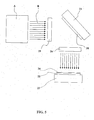
- FIG. 5 illustrates the use of an EUV source according to the invention for the treatment of a semiconductor wafer.
- the radiation source is illustrated globally and identified by the A.
- the EUV B radiation is directed through the input of the transponder mask, to a mask 20 supported by a mask support device 21.
- the mask 20 is reflective, and redirects the radiation, through the optical reducer 26 of the mask repeater, to a semiconductor wafer 22 itself supported by a wafer carrier 23.
- the semiconductor wafer 22 for example comprises a surface covered with a layer 24 that is to be treated by the EUV radiation, according to the pattern of the mask 20, with a reduction factor determined by the optical reducer 26.
Landscapes
- Physics & Mathematics (AREA)
- Engineering & Computer Science (AREA)
- Optics & Photonics (AREA)
- Plasma & Fusion (AREA)
- Nanotechnology (AREA)
- Chemical & Material Sciences (AREA)
- Mathematical Physics (AREA)
- Theoretical Computer Science (AREA)
- Crystallography & Structural Chemistry (AREA)
- General Physics & Mathematics (AREA)
- Exposure And Positioning Against Photoresist Photosensitive Materials (AREA)
- Exposure Of Semiconductors, Excluding Electron Or Ion Beam Exposure (AREA)
- X-Ray Techniques (AREA)
- Transition And Organic Metals Composition Catalysts For Addition Polymerization (AREA)
Abstract
Description
- la zone d'irradiation est située dans une chambre d'irradiation connectée à des premiers moyens générateurs de vide entretenant une première pression,
- les moyens pour recueillir et conditionner la radiation EUV émise sont placés dans une chambre de transmission qui est connectée à des seconds moyens générateurs de vide entretenant une seconde pression inférieure à la première pression,
- la chambre de transmission communique avec la chambre d'irradiation par un diaphragme de dimension réduite prévu à proximité immédiate de la zone d'irradiation et orienté selon un axe optique,
- le flux de matériau générateur de radiation dans la zone d'irradiation est orienté selon une direction transversale par rapport à l'axe optique.
- la figure 1 illustre schématiquement une structure générale de source EUV selon un mode de réalisation de la présente invention ;
- la figure 2 est une coupe longitudinale illustrant une réalisation pratique de la source EUV de la figure 1 ;
- la figure 3 est une vue à plus grande échelle montrant la zone d'irradiation de la figure 2 ;
- la figure 4 illustre une variante de réalisation pratique de source EUV selon l'invention ; et
- la figure 5 illustre l'application de la source EUV selon l'invention dans un dispositif de photolithographie.
Claims (15)
- Source de radiation dans l'Extrême Ultra Violet (EUV) comprenant des moyens (7, 15) pour injecter à l'entrée d'une zone d'irradiation (3) un flux de matériau générateur de radiation, des moyens (8, 16) pour recueillir le flux de matériau générateur de radiation en sortie de la zone d'irradiation (3), des moyens pour générer et focaliser un rayonnement laser de puissance (5, 6) sur le matériau générateur de radiation dans la zone d'irradiation (3), et des moyens (13) pour recueillir et conditionner la radiation EUV émise par le matériau générateur de radiation dans la zone d'irradiation (3), des premiers moyens générateurs de vide (11) connectés à une chambre d'irradiation (1) dans laquelle est située la zone d'irradiation (3) entretenant une première pression (P1), caractérisée en ce que:les moyens (13) pour recueillir et conditionner la radiation EUV émise sont placés dans une chambre de transmission (2) qui est connectée à des seconds moyens générateurs de vide (12) entretenant une seconde pression (P2) inférieure à la première pression (P1),la chambre de transmission (2) communique avec la chambre d'irradiation (1) par un diaphragme (4) de dimension réduite prévu à proximité immédiate de la zone d'irradiation (3) et orienté selon un axe optique (I-I),le flux de matériau générateur de radiation dans zone d'irradiation (3) est orienté selon une direction (II-II) transversale par rapport à l'axe optique (I-I).
- Source de radiation selon la revendication 1, caractérisée ce que la seconde pression (P2) est inférieure ou égale au dixième de la première pression (P1).
- Source de radiation selon l'une des revendication 1 ou 2, caractérisée en ce que la première pression (P1) est inférieure, ou égale à 5 10 -3 millibars, tandis que la seconde pression (P2) est inférieure ou égale à 5 10 -4millibars.
- Source de radiation selon l'une quelconque des revendications 1 à 3, caractérisée en ce que le matériau générateur de radiation est du xénon gazeux.
- Source de radiation selon l'une quelconque des revendications 1 à 3, caractérisée en ce que le matériau générateur de radiation est du xénon liquide.
- Source de radiation selon l'une quelconque des revendications 1 à 3, caractérisée en ce que le matériau générateur de radiation est l'étain.
- Source de radiation selon l'une quelconque des revendications 1 à 6, caractérisée en ce que le rayonnement laser de puissance frappe le flux de matériau générateur de radiation sur la face du flux qui est orientée vers le diaphragme (4).
- Source de radiation selon l'une quelconque des revendications 1 à 7, caractérisée en ce que le rayonnement laser de puissance est constitué d'une pluralité de rayons laser qui convergent vers la zone d'irradiation (3).
- Source de radiation selon la revendication 8, caractérisée en ce que les rayons laser de puissance (5, 6) incidents pénètrent dans la chambre d'irradiation (1) en traversant le diaphragme (4).
- Source de radiation selon la revendication 8, caractérisée en ce que les rayons laser de puissance (6, 6) pénètrent dans la chambre d'irradiation en amont du diaphragme (4), et se propagent vers la zone d'irradiation (3) le long de la paroi intermédiaire (4a), le diaphragme (4) étant lui-même réalisé dans une paroi intermédiaire (4a) de forme conique à sommet dirigé vers la zone d'irradiation (3).
- Source de radiation selon l'une quelconque des revendications 1 à 10, caractérisée en ce que la, chambre de transmission (2) comprend un ou plusieurs miroirs elliptiques (13a, 13b) orientés selon l'axe optique (I-I) et dont un foyer est situé dans la zone d'irradiation (3).
- Source de radiation selon l'une quelconque des revendications 1 à 11, caractérisée en ce qu'elle comprend en outre un dispositif anti-débris (14) prévu dans la chambre de transmission (2) en regard et à proximité du diaphragme (4), pour transmettre le, rayonnement EUV aux moyens (13) pour recueillir et conditionner la radiation EUV émise tout en s'opposant au passage des ions et autres particules provenant de la chambre d'irradiation (1).
- Source de radiation selon la revendication 12, caractérisée en ce que le dispositif anti-débris (14) comprend un flux transversal d'hélium, d'argon ou de krypton en aval du diaphragme (4).
- Dispositif de photolithographie, comprenant une source de radiation EUV (A) pour générer une radiation EUV (B), un dispositif support de masque (21) adapté pour supporter un masque (20), un support de Plaquettes de semi-conducteur (23) adapté pour supporter une plaquette de semi-conducteur (22) à traiter, et un système optique (25, 26) adapté pour projeter sur la plaquette de semi-conducteur (22) une image d'une portion du masque (20) irradiée par la radiation EUV (B), caractérisé en ce que la source de radiation (A) est une source selon l'une quelconque des revendications 1 à 13.
- Dispositif de photolithographie selon la revendication 14, caractérisé en ce que la source de radiation (A) comprend des miroirs elliptiques dont un foyer est à l'entrée (25) du système optique (25, 26), pour focaliser la radiation EUV (B) à l'entrée (25) du système optique (25, 26).
Applications Claiming Priority (2)
| Application Number | Priority Date | Filing Date | Title |
|---|---|---|---|
| FR0311280A FR2860385B1 (fr) | 2003-09-26 | 2003-09-26 | Source euv |
| FR0311280 | 2003-09-26 |
Publications (3)
| Publication Number | Publication Date |
|---|---|
| EP1528846A2 true EP1528846A2 (fr) | 2005-05-04 |
| EP1528846A3 EP1528846A3 (fr) | 2005-06-08 |
| EP1528846B1 EP1528846B1 (fr) | 2009-12-23 |
Family
ID=34307180
Family Applications (1)
| Application Number | Title | Priority Date | Filing Date |
|---|---|---|---|
| EP04292256A Expired - Lifetime EP1528846B1 (fr) | 2003-09-26 | 2004-09-20 | Source EUV |
Country Status (6)
| Country | Link |
|---|---|
| US (1) | US7095038B2 (fr) |
| EP (1) | EP1528846B1 (fr) |
| JP (1) | JP4690686B2 (fr) |
| AT (1) | ATE453309T1 (fr) |
| DE (1) | DE602004024754D1 (fr) |
| FR (1) | FR2860385B1 (fr) |
Families Citing this family (17)
| Publication number | Priority date | Publication date | Assignee | Title |
|---|---|---|---|---|
| US7439530B2 (en) | 2005-06-29 | 2008-10-21 | Cymer, Inc. | LPP EUV light source drive laser system |
| US7034320B2 (en) * | 2003-03-20 | 2006-04-25 | Intel Corporation | Dual hemispherical collectors |
| JP2005190904A (ja) * | 2003-12-26 | 2005-07-14 | Ushio Inc | 極端紫外光源 |
| US7482609B2 (en) * | 2005-02-28 | 2009-01-27 | Cymer, Inc. | LPP EUV light source drive laser system |
| EP2020165B1 (fr) | 2006-05-16 | 2010-11-24 | Philips Intellectual Property & Standards GmbH | Procédé permettant d'améliorer l'efficacité de conversion d'une lampe à rayonnement uv extrême et/ou à rayons x mous et appareil correspondant |
| US7655925B2 (en) * | 2007-08-31 | 2010-02-02 | Cymer, Inc. | Gas management system for a laser-produced-plasma EUV light source |
| CN101849212A (zh) * | 2007-11-08 | 2010-09-29 | Asml荷兰有限公司 | 辐射系统和方法以及光谱纯度滤光片 |
| EP2083328B1 (fr) * | 2008-01-28 | 2013-06-19 | Media Lario s.r.l. | Collecteur d'incidence rasante pour sources à plasma produites par laser |
| EP2182412A1 (fr) * | 2008-11-04 | 2010-05-05 | ASML Netherlands B.V. | Source de radiation et appareil lithographique |
| US8330131B2 (en) * | 2010-01-11 | 2012-12-11 | Media Lario, S.R.L. | Source-collector module with GIC mirror and LPP EUV light source |
| WO2012177900A1 (fr) | 2011-06-22 | 2012-12-27 | Research Triangle Institute, International | Dispositif microélectronique bipolaire |
| US20150097107A1 (en) * | 2012-03-20 | 2015-04-09 | Fst Inc. | Apparatus for generating extreme ultraviolet light using plasma |
| WO2013189827A2 (fr) | 2012-06-22 | 2013-12-27 | Asml Netherlands B.V. | Source de rayonnement et appareil lithographique |
| US10880979B2 (en) | 2015-11-10 | 2020-12-29 | Kla Corporation | Droplet generation for a laser produced plasma light source |
| US10021773B2 (en) | 2015-11-16 | 2018-07-10 | Kla-Tencor Corporation | Laser produced plasma light source having a target material coated on a cylindrically-symmetric element |
| US9918375B2 (en) * | 2015-11-16 | 2018-03-13 | Kla-Tencor Corporation | Plasma based light source having a target material coated on a cylindrically-symmetric element |
| KR102024760B1 (ko) * | 2018-01-18 | 2019-09-25 | 한국원자력연구원 | 빔집속장치 |
Family Cites Families (9)
| Publication number | Priority date | Publication date | Assignee | Title |
|---|---|---|---|---|
| JPH01137543A (ja) * | 1987-11-24 | 1989-05-30 | Fujitsu Ltd | レーザ励起x線発生装置 |
| JPH0837096A (ja) * | 1994-07-26 | 1996-02-06 | Nikon Corp | X線発生装置 |
| JPH10221499A (ja) * | 1997-02-07 | 1998-08-21 | Hitachi Ltd | レーザプラズマx線源およびそれを用いた半導体露光装置並びに半導体露光方法 |
| US6541786B1 (en) * | 1997-05-12 | 2003-04-01 | Cymer, Inc. | Plasma pinch high energy with debris collector |
| JP2000089000A (ja) * | 1998-09-14 | 2000-03-31 | Nikon Corp | X線発生装置 |
| DE19962160C2 (de) * | 1999-06-29 | 2003-11-13 | Fraunhofer Ges Forschung | Vorrichtungen zur Erzeugung von Extrem-Ultraviolett- und weicher Röntgenstrahlung aus einer Gasentladung |
| US6304630B1 (en) * | 1999-12-24 | 2001-10-16 | U.S. Philips Corporation | Method of generating EUV radiation, method of manufacturing a device by means of said radiation, EUV radiation source unit, and lithographic projection apparatus provided with such a radiation source unit |
| JP4351413B2 (ja) * | 2002-03-05 | 2009-10-28 | 望月 孝晏 | レーザプラズマx線発生装置 |
| DE10251435B3 (de) * | 2002-10-30 | 2004-05-27 | Xtreme Technologies Gmbh | Strahlungsquelle zur Erzeugung von extrem ultravioletter Strahlung |
-
2003
- 2003-09-26 FR FR0311280A patent/FR2860385B1/fr not_active Expired - Fee Related
-
2004
- 2004-09-20 DE DE602004024754T patent/DE602004024754D1/de not_active Expired - Lifetime
- 2004-09-20 AT AT04292256T patent/ATE453309T1/de not_active IP Right Cessation
- 2004-09-20 EP EP04292256A patent/EP1528846B1/fr not_active Expired - Lifetime
- 2004-09-21 JP JP2004272681A patent/JP4690686B2/ja not_active Expired - Fee Related
- 2004-09-22 US US10/946,109 patent/US7095038B2/en not_active Expired - Fee Related
Non-Patent Citations (1)
| Title |
|---|
| None |
Also Published As
| Publication number | Publication date |
|---|---|
| EP1528846B1 (fr) | 2009-12-23 |
| JP4690686B2 (ja) | 2011-06-01 |
| EP1528846A3 (fr) | 2005-06-08 |
| US20050072942A1 (en) | 2005-04-07 |
| JP2005108834A (ja) | 2005-04-21 |
| FR2860385A1 (fr) | 2005-04-01 |
| DE602004024754D1 (de) | 2010-02-04 |
| ATE453309T1 (de) | 2010-01-15 |
| US7095038B2 (en) | 2006-08-22 |
| FR2860385B1 (fr) | 2007-06-01 |
Similar Documents
| Publication | Publication Date | Title |
|---|---|---|
| EP1528846B1 (fr) | Source EUV | |
| EP1800188B1 (fr) | Dispositif de generation de lumiere dans l' extreme ultraviolet et application a une source de lithographie par rayonnement dans l'extreme ultraviolet | |
| EP2473315B1 (fr) | Tete de focalisation laser avec des lentilles en zns ayant une epaisseur aux bords d'au moins 5 mm ; installation et procede de coupage laser employant une telle tete de focalisation | |
| US20150049778A1 (en) | System and Method for Separation of Pump Light and Collected Light in a Laser Pumped Light Source | |
| JP7544848B2 (ja) | ガス渦流を有するレーザ強化プラズマ光源 | |
| EP1382230A1 (fr) | Procede et dispositif de generation de lumiere dans l'extreme ultraviolet notamment pour la lithographie | |
| JP2005108834A5 (fr) | ||
| EP2195643A1 (fr) | Systeme d'analyse de gaz a basse pression par spectroscopie d'emission optique | |
| FR2604050A1 (fr) | Appareil et procede de creation d'un faisceau monoenergetique de particules et produits obtenus par leur mise en oeuvre | |
| FR3087276A1 (fr) | Systeme et procede de compression d'impulsions lumineuses breves ou ultrabreves et systeme laser a impulsions lumineuses associe | |
| JP5448402B2 (ja) | ガスフロー式spfを備えた極端紫外光源装置 | |
| FR2678418A1 (fr) | Procede de travail au laser dans une zone contaminee d'une installation nucleaire, et equipement pour sa mise en óoeuvre. | |
| CN117121155A (zh) | 具有反向涡流的激光维持等离子体光源 | |
| EP0507641B1 (fr) | Procédé et équipement de travail au laser dans une zone contaminée d'une installation nucléaire | |
| TW202442034A (zh) | 高功率緊湊型真空紫外線(vuv)雷射維持電漿光源 | |
| FR2784674A1 (fr) | Dispositif d'epuration de fluide par impulsions photoniques | |
| FR2879101A1 (fr) | Decontamination laser de la surface d'une piece profilee. | |
| FR2623820A1 (fr) | Depot en phase gazeuse par procede chimique a laser avec utilisation d'un faisceau a fibre optique | |
| EP1869695A2 (fr) | Dispositif micro-onde pour le traitement d'un flux par un rayonnement lumineux | |
| FR3083223A1 (fr) | Systeme de desinfection et de traitement d'eau par irradiation ultraviolette | |
| WO1999036939A1 (fr) | Tube, dispositif et procede emetteur de rayonnements electromagnetiques | |
| WO1983004099A1 (fr) | Procede et dispositf de production de photons dans la gamme des longueurs d'ondes ultraviolettes | |
| FR2542104A1 (fr) | Procede et dispositif de creation d'impulsions lumineuses breves | |
| EP1317033B1 (fr) | Amplificateur d'un faisceau laser par pompage d'un matériau non linéaire et dispositif d'émission laser comportant un tel amplificateur | |
| FR3159239A1 (fr) | Procede de realisation d’une galette de microcannaux, tube intensificateur d’images et systeme de vision nocturne associes |
Legal Events
| Date | Code | Title | Description |
|---|---|---|---|
| PUAI | Public reference made under article 153(3) epc to a published international application that has entered the european phase |
Free format text: ORIGINAL CODE: 0009012 |
|
| PUAL | Search report despatched |
Free format text: ORIGINAL CODE: 0009013 |
|
| AK | Designated contracting states |
Kind code of ref document: A2 Designated state(s): AT BE BG CH CY CZ DE DK EE ES FI FR GB GR HU IE IT LI LU MC NL PL PT RO SE SI SK TR |
|
| AX | Request for extension of the european patent |
Extension state: AL HR LT LV MK |
|
| AK | Designated contracting states |
Kind code of ref document: A3 Designated state(s): AT BE BG CH CY CZ DE DK EE ES FI FR GB GR HU IE IT LI LU MC NL PL PT RO SE SI SK TR |
|
| AX | Request for extension of the european patent |
Extension state: AL HR LT LV MK |
|
| 17P | Request for examination filed |
Effective date: 20051208 |
|
| AKX | Designation fees paid |
Designated state(s): AT BE BG CH CY CZ DE DK EE ES FI FR GB GR HU IE IT LI LU MC NL PL PT RO SE SI SK TR |
|
| 17Q | First examination report despatched |
Effective date: 20060201 |
|
| RAP1 | Party data changed (applicant data changed or rights of an application transferred) |
Owner name: ALCATEL LUCENT |
|
| GRAP | Despatch of communication of intention to grant a patent |
Free format text: ORIGINAL CODE: EPIDOSNIGR1 |
|
| GRAS | Grant fee paid |
Free format text: ORIGINAL CODE: EPIDOSNIGR3 |
|
| GRAA | (expected) grant |
Free format text: ORIGINAL CODE: 0009210 |
|
| AK | Designated contracting states |
Kind code of ref document: B1 Designated state(s): AT BE BG CH CY CZ DE DK EE ES FI FR GB GR HU IE IT LI LU MC NL PL PT RO SE SI SK TR |
|
| REG | Reference to a national code |
Ref country code: GB Ref legal event code: FG4D Free format text: NOT ENGLISH |
|
| REG | Reference to a national code |
Ref country code: CH Ref legal event code: EP |
|
| REG | Reference to a national code |
Ref country code: IE Ref legal event code: FG4D |
|
| REF | Corresponds to: |
Ref document number: 602004024754 Country of ref document: DE Date of ref document: 20100204 Kind code of ref document: P |
|
| REG | Reference to a national code |
Ref country code: NL Ref legal event code: VDEP Effective date: 20091223 |
|
| PG25 | Lapsed in a contracting state [announced via postgrant information from national office to epo] |
Ref country code: SE Free format text: LAPSE BECAUSE OF FAILURE TO SUBMIT A TRANSLATION OF THE DESCRIPTION OR TO PAY THE FEE WITHIN THE PRESCRIBED TIME-LIMIT Effective date: 20091223 Ref country code: FI Free format text: LAPSE BECAUSE OF FAILURE TO SUBMIT A TRANSLATION OF THE DESCRIPTION OR TO PAY THE FEE WITHIN THE PRESCRIBED TIME-LIMIT Effective date: 20091223 |
|
| PG25 | Lapsed in a contracting state [announced via postgrant information from national office to epo] |
Ref country code: PL Free format text: LAPSE BECAUSE OF FAILURE TO SUBMIT A TRANSLATION OF THE DESCRIPTION OR TO PAY THE FEE WITHIN THE PRESCRIBED TIME-LIMIT Effective date: 20091223 Ref country code: SI Free format text: LAPSE BECAUSE OF FAILURE TO SUBMIT A TRANSLATION OF THE DESCRIPTION OR TO PAY THE FEE WITHIN THE PRESCRIBED TIME-LIMIT Effective date: 20091223 |
|
| PG25 | Lapsed in a contracting state [announced via postgrant information from national office to epo] |
Ref country code: AT Free format text: LAPSE BECAUSE OF FAILURE TO SUBMIT A TRANSLATION OF THE DESCRIPTION OR TO PAY THE FEE WITHIN THE PRESCRIBED TIME-LIMIT Effective date: 20091223 |
|
| REG | Reference to a national code |
Ref country code: IE Ref legal event code: FD4D |
|
| PG25 | Lapsed in a contracting state [announced via postgrant information from national office to epo] |
Ref country code: NL Free format text: LAPSE BECAUSE OF FAILURE TO SUBMIT A TRANSLATION OF THE DESCRIPTION OR TO PAY THE FEE WITHIN THE PRESCRIBED TIME-LIMIT Effective date: 20091223 Ref country code: BG Free format text: LAPSE BECAUSE OF FAILURE TO SUBMIT A TRANSLATION OF THE DESCRIPTION OR TO PAY THE FEE WITHIN THE PRESCRIBED TIME-LIMIT Effective date: 20100323 Ref country code: ES Free format text: LAPSE BECAUSE OF FAILURE TO SUBMIT A TRANSLATION OF THE DESCRIPTION OR TO PAY THE FEE WITHIN THE PRESCRIBED TIME-LIMIT Effective date: 20100403 Ref country code: EE Free format text: LAPSE BECAUSE OF FAILURE TO SUBMIT A TRANSLATION OF THE DESCRIPTION OR TO PAY THE FEE WITHIN THE PRESCRIBED TIME-LIMIT Effective date: 20091223 Ref country code: RO Free format text: LAPSE BECAUSE OF FAILURE TO SUBMIT A TRANSLATION OF THE DESCRIPTION OR TO PAY THE FEE WITHIN THE PRESCRIBED TIME-LIMIT Effective date: 20091223 Ref country code: PT Free format text: LAPSE BECAUSE OF FAILURE TO SUBMIT A TRANSLATION OF THE DESCRIPTION OR TO PAY THE FEE WITHIN THE PRESCRIBED TIME-LIMIT Effective date: 20100423 |
|
| PG25 | Lapsed in a contracting state [announced via postgrant information from national office to epo] |
Ref country code: SK Free format text: LAPSE BECAUSE OF FAILURE TO SUBMIT A TRANSLATION OF THE DESCRIPTION OR TO PAY THE FEE WITHIN THE PRESCRIBED TIME-LIMIT Effective date: 20091223 Ref country code: CZ Free format text: LAPSE BECAUSE OF FAILURE TO SUBMIT A TRANSLATION OF THE DESCRIPTION OR TO PAY THE FEE WITHIN THE PRESCRIBED TIME-LIMIT Effective date: 20091223 |
|
| PG25 | Lapsed in a contracting state [announced via postgrant information from national office to epo] |
Ref country code: CY Free format text: LAPSE BECAUSE OF FAILURE TO SUBMIT A TRANSLATION OF THE DESCRIPTION OR TO PAY THE FEE WITHIN THE PRESCRIBED TIME-LIMIT Effective date: 20091223 Ref country code: GR Free format text: LAPSE BECAUSE OF FAILURE TO SUBMIT A TRANSLATION OF THE DESCRIPTION OR TO PAY THE FEE WITHIN THE PRESCRIBED TIME-LIMIT Effective date: 20100324 Ref country code: IE Free format text: LAPSE BECAUSE OF FAILURE TO SUBMIT A TRANSLATION OF THE DESCRIPTION OR TO PAY THE FEE WITHIN THE PRESCRIBED TIME-LIMIT Effective date: 20091223 |
|
| PLBE | No opposition filed within time limit |
Free format text: ORIGINAL CODE: 0009261 |
|
| STAA | Information on the status of an ep patent application or granted ep patent |
Free format text: STATUS: NO OPPOSITION FILED WITHIN TIME LIMIT |
|
| PGFP | Annual fee paid to national office [announced via postgrant information from national office to epo] |
Ref country code: FR Payment date: 20101005 Year of fee payment: 7 |
|
| 26N | No opposition filed |
Effective date: 20100924 |
|
| PG25 | Lapsed in a contracting state [announced via postgrant information from national office to epo] |
Ref country code: DK Free format text: LAPSE BECAUSE OF FAILURE TO SUBMIT A TRANSLATION OF THE DESCRIPTION OR TO PAY THE FEE WITHIN THE PRESCRIBED TIME-LIMIT Effective date: 20091223 |
|
| PGFP | Annual fee paid to national office [announced via postgrant information from national office to epo] |
Ref country code: DE Payment date: 20100922 Year of fee payment: 7 |
|
| BERE | Be: lapsed |
Owner name: ALCATEL LUCENT Effective date: 20100930 |
|
| PG25 | Lapsed in a contracting state [announced via postgrant information from national office to epo] |
Ref country code: IT Free format text: LAPSE BECAUSE OF FAILURE TO SUBMIT A TRANSLATION OF THE DESCRIPTION OR TO PAY THE FEE WITHIN THE PRESCRIBED TIME-LIMIT Effective date: 20091223 |
|
| PG25 | Lapsed in a contracting state [announced via postgrant information from national office to epo] |
Ref country code: MC Free format text: LAPSE BECAUSE OF NON-PAYMENT OF DUE FEES Effective date: 20100930 |
|
| REG | Reference to a national code |
Ref country code: CH Ref legal event code: PL |
|
| GBPC | Gb: european patent ceased through non-payment of renewal fee |
Effective date: 20100920 |
|
| PG25 | Lapsed in a contracting state [announced via postgrant information from national office to epo] |
Ref country code: LI Free format text: LAPSE BECAUSE OF NON-PAYMENT OF DUE FEES Effective date: 20100930 Ref country code: BE Free format text: LAPSE BECAUSE OF NON-PAYMENT OF DUE FEES Effective date: 20100930 Ref country code: CH Free format text: LAPSE BECAUSE OF NON-PAYMENT OF DUE FEES Effective date: 20100930 |
|
| PG25 | Lapsed in a contracting state [announced via postgrant information from national office to epo] |
Ref country code: GB Free format text: LAPSE BECAUSE OF NON-PAYMENT OF DUE FEES Effective date: 20100920 |
|
| REG | Reference to a national code |
Ref country code: FR Ref legal event code: ST Effective date: 20120531 |
|
| PG25 | Lapsed in a contracting state [announced via postgrant information from national office to epo] |
Ref country code: DE Free format text: LAPSE BECAUSE OF NON-PAYMENT OF DUE FEES Effective date: 20120403 |
|
| REG | Reference to a national code |
Ref country code: DE Ref legal event code: R119 Ref document number: 602004024754 Country of ref document: DE Effective date: 20120403 |
|
| PG25 | Lapsed in a contracting state [announced via postgrant information from national office to epo] |
Ref country code: FR Free format text: LAPSE BECAUSE OF NON-PAYMENT OF DUE FEES Effective date: 20110930 |
|
| PG25 | Lapsed in a contracting state [announced via postgrant information from national office to epo] |
Ref country code: HU Free format text: LAPSE BECAUSE OF FAILURE TO SUBMIT A TRANSLATION OF THE DESCRIPTION OR TO PAY THE FEE WITHIN THE PRESCRIBED TIME-LIMIT Effective date: 20100624 Ref country code: LU Free format text: LAPSE BECAUSE OF NON-PAYMENT OF DUE FEES Effective date: 20100920 |
|
| PG25 | Lapsed in a contracting state [announced via postgrant information from national office to epo] |
Ref country code: TR Free format text: LAPSE BECAUSE OF FAILURE TO SUBMIT A TRANSLATION OF THE DESCRIPTION OR TO PAY THE FEE WITHIN THE PRESCRIBED TIME-LIMIT Effective date: 20091223 |
|
| REG | Reference to a national code |
Ref country code: FR Ref legal event code: CA Effective date: 20150521 |
|
| REG | Reference to a national code |
Ref country code: FR Ref legal event code: CA Effective date: 20150521 |