EP1528480A1 - Bussystem mit wenigen Steuerleitungen - Google Patents
Bussystem mit wenigen Steuerleitungen Download PDFInfo
- Publication number
- EP1528480A1 EP1528480A1 EP04025603A EP04025603A EP1528480A1 EP 1528480 A1 EP1528480 A1 EP 1528480A1 EP 04025603 A EP04025603 A EP 04025603A EP 04025603 A EP04025603 A EP 04025603A EP 1528480 A1 EP1528480 A1 EP 1528480A1
- Authority
- EP
- European Patent Office
- Prior art keywords
- bus
- data
- eaibc
- iaibc
- control
- Prior art date
- Legal status (The legal status is an assumption and is not a legal conclusion. Google has not performed a legal analysis and makes no representation as to the accuracy of the status listed.)
- Granted
Links
Images


Classifications
-
- G—PHYSICS
- G06—COMPUTING; CALCULATING OR COUNTING
- G06F—ELECTRIC DIGITAL DATA PROCESSING
- G06F13/00—Interconnection of, or transfer of information or other signals between, memories, input/output devices or central processing units
- G06F13/38—Information transfer, e.g. on bus
- G06F13/40—Bus structure
- G06F13/4004—Coupling between buses
- G06F13/4027—Coupling between buses using bus bridges
- G06F13/4045—Coupling between buses using bus bridges where the bus bridge performs an extender function
-
- G—PHYSICS
- G06—COMPUTING; CALCULATING OR COUNTING
- G06F—ELECTRIC DIGITAL DATA PROCESSING
- G06F13/00—Interconnection of, or transfer of information or other signals between, memories, input/output devices or central processing units
- G06F13/38—Information transfer, e.g. on bus
- G06F13/42—Bus transfer protocol, e.g. handshake; Synchronisation
- G06F13/4204—Bus transfer protocol, e.g. handshake; Synchronisation on a parallel bus
- G06F13/4221—Bus transfer protocol, e.g. handshake; Synchronisation on a parallel bus being an input/output bus, e.g. ISA bus, EISA bus, PCI bus, SCSI bus
- G06F13/423—Bus transfer protocol, e.g. handshake; Synchronisation on a parallel bus being an input/output bus, e.g. ISA bus, EISA bus, PCI bus, SCSI bus with synchronous protocol
Definitions
- the invention relates to a bus system with a bus according to the preamble features of claim 1, a thus formed interface bus and a control method for such a bus.
- bus systems which bus interfaces for connecting the data transmitting devices having.
- bus interfaces for connecting the data transmitting devices having.
- master controlling bus device
- slave serving bus device
- DMA direct memory access
- buses are used to transfer data between various devices used, the control of the Data bus taken from a central computer (CPU) becomes.
- the central computing device in addition to the data bus for data transmission an address bus to Transmission of the address of the device of the computer on, from which or from which a data transmission via the data bus is to take place.
- the control lines serve or a tax bus to, the date of transfer to be determined via the data bus. It is thus a central control of data transmission via the data bus, in which the central control device the release the data bus for each connected device causes.
- the processor attaches the data to the Data lines of the data bus and triggers a write pulse out.
- the peripheral device acknowledges the retrieval of the data the acknowledge signal, whereupon by resetting the interrupt signal the processor is signaled that the data bus ready for a new transfer. Also with this Arrangement takes place the assignment of the data bus for transmission data about each connected device thus from the central processor.
- Hardware interrupts directed to interrupt control devices, which also a prioritization of various incoming parallel Allow requests for allocation of the data bus.
- Conventional bus systems thus have a data bus, an address bus and a control bus or corresponding signaling and Control cables on.
- a bus is needed fast, with few leads, few o-leads (Overload) has and different types of transfers allows, for example, registers and memory individually addressed or direct memory access (DMA) allows.
- DMA direct memory access
- the object of the invention is a bus system with a Bus provide, which in particular as an interface between a processor core with standard bus connection and Interface devices to other system devices and peripheral devices is formed.
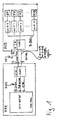
- Fig. 1 illustrates individual functional elements, which for the Understanding the bus system described below helpful are.
- the processor core APX-KERN assigns a common bus R-BUS with data, address and control lines on.
- IAIBC In addition to the processor core APX-KERN, which for example is clocked at 200 MHz, located on the die or APX processor chip a IAIBC bus interface, in which ends the conventional bus R-BUS of the processor APX.
- the bus interface IAIBC which below for the simpler Distinctness as internal bus interface or internal Bus controller IAIBC is set in bidirectional Direction the signals from the conventional bus R-BUS on a bus, which subsequently for easier distinctness as an advanced interface bus AIB (Advanced Interface Bus) is called.
- the to be transmitted Data from or to another bus interface or Bus controller EAIBC which for purposes of distinctness as an external bus control device or bus interface EAIBC is called.
- the external bus interface EAIBC serves as an interface between the interface bus AIB and the other external interface devices IFO - IF15, which interfaces with external facilities are formed.
- This further bus interface EAIBC and the other external interface devices IFO - IF15 are located in turn on a chip or board as an external interface arrangement ASD.
- To the other external interface devices IFO - IF15 can be common facilities for example, a computer or external peripherals be connected in a manner known per se, to the central processor APX and its processor core APX-KERN to communicate. The communication takes place via the intermediate interface bus AIB with, for example 20 MHz instead.
- the bus interfaces IAIBC, EAIBC have equal access to the bus.
- About the three Control lines become read ready signal IAIBC-RTR the internal bus control device or bus interface IAIBC, a read-ready signal EAIBC-RTR of the external bus controller EAIBC or a control signal CTR transmitted.
- control signal CTR in particular the information or data via the interface bus AIB via the data lines be transmitted as payload (user data) or Control data or control words SW identified.
- control signal CTR signals whether via the data lines or the data bus DL currently actual payload or such payload announcing or requesting Control word SW are transmitted.
- the internal Bus controller IAIBC always on the interface bus AIB access when a falling clock edge of the bus clock CL is present.
- the external bus controller EAIBC may accordingly always access the interface bus AIB, when there is a rising clock edge of the bus clock CL.
- the state of the bus clock be used as a criterion, d. H. whether the clock signal is in low or high state.
- bus AIB For such an interface bus AIB is a simple bus protocol usable.
- the bus protocol can based on the following basic principles.
- the external bus controller EAIBC When read-ready signal IAIBC-RTR of the internal Bus controller IAIBC is in the "high” state and in this state "high” via the corresponding control line I-RTR transmitted to the external bus controller EAIBC becomes, the external bus controller EAIBC is characterized signals that the internal bus controller IAIBC for Receiving a control command is ready.
- This readiness signal IAIBC-RTR is issued by the internal bus controller IAIBC generated and at the first of the control lines I-RTR created.
- the control signal or read ready signal IAIBC-RTR is allowed by the internal bus controller IAIBC according to This embodiment always at the time of falling Edge of the clock CL of the interface bus AIB changed become. Alternatively, for example, would be according to another Bus protocol also allowed the change in the state "deep" of the clock CL may be made.
- This Read ready signal EAIBC-RTR is generated and at the second control line E-RTR of the interface bus AIB.
- This read-ready signal EAIBC-RTR serves to internal bus controller IAIBC to signal that the external bus controller EAIBC for receiving a control word or data is ready when the read ready signal EAIBC-RTR is in "high” state.
- This readiness signal EAIBC-RTR is allowed by the external bus controller EAIBC according to the preferred embodiment each together with the rising edge of the clock CL of the Interface bus AIB to be changed. Corresponding is Here, for example, alternatively permitted, changes this Signal during the state "high" of the clock CL make.
- the control command or the control signal CTR can be from both Bus controllers IAIBC, EAIBC via the corresponding third control line CTRL be sent. In normal condition the control signal is in the state "low".
- a control command CTR wants to send out, it sets the control signal CTR for a short time or in the long term in the state "high". To avoid a collision It also states that only the Bus controller IAIBC or EAIBC a control command CTR whose read ready signal IAIBC-RTR or EAIBC-RTR is in the "low” state.
- the timing to raise the state of the control signal CTR falls to avoid collisions e.g. with the time together, to which the corresponding bus control device IAIBC or EAIBC also the state of their read ready signal IAIBC-RTR or EAIBC-RTR may change.
- both transmit bus controllers IAIBC, EAIBC the control signal CTR and an associated one Control word SW in each case with a rising edge of the Clock CL off.
- the internal bus control device may IAIBC a control command CTR on a rising edge of the clock CL of the interface bus AIB.
- the external one Bus controller EAIBC is allowed a control command CTR together with the rising edge of the clock CL of the Create interface bus AIB.
- the corresponding read ready signal IAIBC-RTR or EAIBC-RTR remains in the "low” state, if after the control word SW or control command CTR data or other data to be transmitted. This can by increasing the state of the read ready signal IAIBC-RTR or EAIBC-RTR of the other bus control device EAIBC or IAIBC signals the end of the data transfer become.
- control word SW in particular the type of transfer, z. B. to a register, memory, according to DMA (Direct Memory Access), but also the direction, z. For example, whether to read or to write, and / or the number or address of the addressed External interface device IFO - IF15 announced become.
- DMA Direct Memory Access
- control word SW with the control line marked as such.
- This can then z. B. a read command from the receiving bus controller IAIBC, EAIBC ignored or delayed to itself a control command sell with higher priority.
- Particularly preferred embodiments thus have one Interface bus AIB with three or four control lines.
- these are for transmission the read ready signals IAIBC-RTR, EAIBC-RTR and of the clock CL of the interface bus AIB, wherein the transmission of the control signals CTR completely omitted or also via a correspondingly coded control word SW on the Data lines takes place.
- four Control lines are used for the transmission of the control signal CTR and the transmission of the clock CL of the interface bus AIB each provided their own control lines.
- the Clock signal CL thus has the function of a control signal.
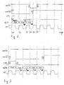
- the state diagram shown in FIG. 2 is exemplary in the case of direct memory access according to DMA (Direct Memory Access) from one of the external interface devices IF0 to a memory in the range of the central processor APX.
- DMA Direct Memory Access
- each of the external interface devices IF0-IF15 a DMA request line on.
- the external interface device IFO sends a DMA request to the external bus controller EAIBC via appropriate direct connection lines or a regular or conventional bus R-BUS.
- the transfer of the request via the interface bus AIB then takes place according to the Scheme described below.
- the external interface device IFO wants to write data to the central storage, sends the External interface device IFO to a DMA request the external bus controller EAIBC.
- the external bus controller EAIBC decides the external bus control device, which meets the requirements highest priority.
- the other requirements are in one Queue queued or rejected.
- the external one Bus controller IAIBC encodes the number or address of the External interface device IF0 and transmits them in a control word SW via the interface bus AIB. The transfer takes place preferably in accordance with the above-described Requirements.
- the internal bus controller AIBC samples the received one Control word SW after the number of the external interface device IFO and checks if there is a reading or write request. If the request is in Form of a control word SW or control command as one Write request is coded, is waiting for, preferably 32 data bits are available to this processor core APX-KERN and at its input port or the R-BUS to apply. Thereafter, the internal bus controller sends IAIBC issues a DMA request and returns it via the interface bus AIB received data on the regular bus R-BUS to the processor core APX-KERN, in case the bus for it from the processor core was released.
- the top line indicates the reception read ready signal IABC-RTR of the internal Control device IAIBC shown.
- the second line is the readiness read / write signal EAIBC-RTR of the external Control device EAIBC shown.
- the control signal CTR shown which on a the control lines CTRL transmitted in bidirectional direction becomes.
- the flow of data especially data packets preferably 16-bit data information per data packet, and the flow of control words SW shown. among them is shown in the last line of the bus clock CL of the Interface bus AIB, by one of the participating institutions or generated externally and to the bus controllers AIBC, EAIBC is created.
- the illustrated signals IAIBC-RTR, EAIBC-RTR, CTR and CL are each in the State "high” h or "deep” 1, these states in after shown on the right side in chronological order can.
- Fig. 2 illustrates the timing signal flow when an external interface device IFO a data packet to the processor core APX-KERN sends.
- the control signal is in the state "low” and a data transfer takes place not happening.
- At a first time t1 is due to the external Bus interface EAIBC to a DMA write request.
- the external bus controller EAIBC the state of their Read ready signal EAIBC-RTR to "low” (1) - (5).
- the external bus controller EAIBC can transfer also slow down or interrupt when the internal Bus controller IAIBC at a later date t4 is not in a ready to receive state, d.
- H. read ready signal IAIBC-RTR of the internal Bus controller in IAIBC are in the "low” state should (4) until a readiness to receive the internal Control IAIBC by corresponding increase of their read-ready signal IAIBC-RTR at a later Time t6 is signaled (6).
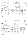
- Fig. 3 shows the case that e.g. the first external interface device IFO sends two or more data packets and not by a delay on the central Bus R-BUS to processor core APX-KERN or other transmissions, for example, from or to other external interface devices IF1 - IF15, delayed or interrupted becomes.
- the read-ready signal is located IAIBC-RTR of the internal bus controller IAIBC consistently in the "high" state.
- the external bus controller EAIBC can do this when creating a transfer request from the external interface device IF0 at the next rising change of the clock CL in the state "high" readiness to read, d. H. the read-ready signal state go "deep" (1).
- control signal CTR in the state offset "high" (2), (3).
- the Control word SW on the data lines DL of the interface bus AIB set. Since the control word SW at the same time an address information contains or may contain serve the data lines DL at the same time as address lines.
- Fig. 4 illustrates the situation in which the external interface device IFO sends data, but through the internal bus controller IAIBC is interrupted.
- EAIBC becomes with the rising clock edge in the presence of to be transmitted Data in the external bus controller EAIBC initiated by this the transfer.
- This is at increasing Clock edge of the clock CL the read-ready signal EAIBC RTR of the external bus controller EAIBC in the state set "low” (1), a control signal CTR via the control line CTRL is activated for one clock period (2) - (3) and on first control word SW on the interface bus AIB or on whose at least one data line is set.
- Preference is given here an embodiment with an interface bus, which 16 data lines DL, so that per clock period, such as this is shown, one control word SW or one complete Data packet DP can be transmitted.
- the external bus controller EAIBC After transmission of the control word SW and two data packets DP detects the external bus controller EAIBC, that the internal bus controller IAIBC half a clock period of the clock CL before the read ready signal IAIBC-RTR into the state "deep" has set (4), thus not ready to receive is.
- the external bus controller EAIBC can then interrupt the transmission of further data or delay.
- the external bus control device goes EAIBC in the state "high” (5) to the internal Bus controller IAIBC ready to signal readiness.
- the internal bus controller IAIBC with the next rising clock edge of the clock CL in turn Activate control signal CTR for one clock period (6) and at the same time a control word SW on the data lines DL of Set interface bus AIB.
- the internal bus controller IAIBC sets data packets DP on the data lines DL.
- the control word SW and the data packets DP are then from the external bus controller EAIBC received, evaluated and the corresponding external interface devices supplied (7).
- the internal bus controller IAIBC sets its read ready signal IAIBC-RTR again in the state "high” and is ready to receive (8). With the next rising Cycle edge, the external bus controller EAIBC thus switch back to the transmission state (9) - (10), as is appropriate the initial transmission of the first control word and the first data packets were described.
- Fig. 5 illustrates the state flow when e.g. the external interface device IFO requests a DMA read. In the example shown, it is assumed that is about a fast and not delayed by the processor APX or interrupted transmission.
- the external bus interface EAIBC has to decide which Requirement has the highest priority. All others will be in queued or rejected a queue.
- the number or address of the external interface device IFO is encoded and together with the DMA request in a control word SW transmitted via the interface bus AIB (1) - (2). If this request is decoded as a read request, the internal bus controller IAIBC will be like one of the internal bus controllers DMA units respond and send a DMA request via the regular bus R-BUS to the processor core APX-KERN. With In a corresponding allocation, it puts the 32-bit data to the regular bus R-BUS between processor core APX-KERN and internal Bus controller IAIBC and clears the request lines.
- the internal bus controller IAIBC sends these Data over the interface bus AIB to the external bus controller EAIBC.
- four data packets DP are transmitted, wherein the first 16-bit data of the 32-bit data in first a data packet based on "high" state and then in one transmit second data packet based on the low state and then transmit the second 16-bit data accordingly become (5).
- the external bus controller EAIBC has completely received the 32-bit data, with the first If necessary, data bits are buffered and sent this to the requesting external interface device IFO. With the caching of the received data deletes the external interface IF0 their request lines and the transfer is terminated.
- Fig. 5 In the state diagram of Fig. 5 is a corresponding sequence shown.
- EAIBC Based on reading readiness of the two Bus controllers IAIBC, EAIBC switches the external Bus controller EAIBC after the arrival of a DMA read request at the next rising clock edge of one of the external interface devices in the non-read-ready state (1).
- the external submits Bus controller EAIBC the control signal on the control line CTR for one clock period in the state "high" (2). additionally becomes from the external bus controller EAIBC a corresponding request generated and as the control word SW via the data lines DL transferred to the interface bus AIB.
- the internal bus controller IAIBC receives this Control word SW and switches in the ideal case according to Forwarding to the processor core APX-KERN, already half Clock period later with the next falling clock edge of the clock CL in the non-read-ready state (3). thereupon turns on the external bus controller EAIBC preferably already the next rising clock edge of Clock CL again in the state of readiness to receive and signals this by raising the read ready signal EAIBC-RTR (4).
- the internal bus controller IAIBC can now in the meantime on the regular bus R-BUS from the processor core APX-KERN, received data with the next clocks of the clock CL on the data lines DL of Create interface bus AIB.
- the waiting for data packets External bus controller receives these data packets DL from Interface bus AIB and forwards these to the requesting external interface device IFO (5).
- the receive memory of the external bus controller EAIBC When the receive memory of the external bus controller EAIBC is full signals the external bus controller EAIBC this the internal bus controller IAIBC by the Downsetting the ready-to-receive signal EAIBC-RTR with the next rising clock edge of the clock CL (6).
- the internal Bus controller IAIBC then stops sending the data up to a readiness to receive the external Bus controller EAIBC.
- closes the internal bus control device IAIBC also leads and puts himself in the state for receiving new commands by incrementing the Read ready signal IAIBC-RTR (7).
- the external bus controller EAIBC holds her readiness signal EAIBC-RTR while in this state (8), at least for one clock cycle of the clock CL in the low state until the memory free again is or, as in the illustrated embodiment, a new DMA request by the external interface device IFO or other external interface device IF1 - IF15 arrives at her. Then, in turn, one Control command CTR is set to the control line CTRL (9) and a control word SW to the data lines DL of the interface bus AIB created (10).
- Fig. 6 describes the case where the external interface device IF0 requests a single data transfer, the however, by the usual bus R-BUS between the internal Bus controller IAIBC and the processor core APX-KERN delayed is performed when the processor core APX-KERN the can not provide requested data fast enough.
- the starting point is a readiness readiness of both bus control devices IAIBC, EAIBC.
- EAIBC After receiving the data request from the external interface IF0 changes the external Bus controller EAIBC read readiness signal EAIBC-RTR in the non-ready state (1) to send at the same time a control signal CTR via the control line (2) and sends a command or control word SW over the data lines DL to the internal bus controller IAIBC. This happens, as in the previous embodiments, together with the rising edge of the clock CL.
- a blockage of the interface bus AIB is thus reduced to the time actually spent on the Transmission of control words SW and data packets DP required is.
- the internal bus controller IAIBC After the existence of the data to be transmitted or Data packets DP and switch to non-read-ready state sends the internal bus controller IAIBC the data as data packets DP via the data lines DL, where according to the exemplary format in the next bars again one or two 16-bit data packets are transmitted.
- the external bus controller EAIBC can transfer slow down or interrupt, if their receive memory is full by the read ready signal EAIBC-RTR for transmitting a new control word SW and sending a Control signal or control command CTR via the control line CTRL (8) for one clock cycle in the state "deep" becomes (7).
- the internal bus controller IAIBC after transmission of data packets DP (5) in the meantime changed to reading readiness state (6) is.
- This transmission of another control word SW by the external bus controller is thus either by going over the internal bus controller IAIBC in FIG the readiness to read (6) or a lack of ability of the external Bus controller EAIBC for receiving further data triggered.
- Another reason for sending out another Control word SW can also consist in that the external Bus controller EAIBC, for example, another, under Circumstances more urgent DMA request with the control word SW via the interface bus AIB in the direction of the processor core APX-KERN has to send.
- Embodiment remains the external bus control device EAIBC after sending the DMA request or the corresponding one Control word SW (7, 8) immediately read-ready (10), to receive the urgently awaited data DP promptly and after the end of the transmission via the interface bus AIB (11) to the requesting external interface device IFO to be able to forward (12).
- Fig. 7 shows an embodiment of the procedure for the Case that an external interface IF0 requests data, being a fast transfer through the processor core APX-KERN is interrupted.
- the external bus controller EAIBC sends the external bus controller EAIBC in already described Way a first control word SW over the Interface bus AIB to the internal bus controller IAIBC.
- the internal bus controller IAIBC decodes this control word and calls from the processor core APX-KERN over the conventional Bus R-BUS on the part of the external interface device IF0 requested data.
- IAIBC already after one half clock announces the internal bus controller IAIBC by lowering the read-ready signal IAIBC-RTR, that the data is ready and put it on the interface bus AIB wants to access (1, 2, 3).
- the external bus controller EAIBC interrupts the sending of further data or control words and already goes into the Read Standby state after one clock cycle (4).
- the external bus controller now expects the requested Data on the data lines DL. She gets from the internal bus controller IAIBC a higher priority Control Word SW * transmitted over the data lines DL (5). According to the selected data format then follow data packets (6) via the data lines DL of the interface bus AIB, which belong directly to the higher priority control word SW *.
- the internal bus control device goes again in read-ready state (7).
- the external one Bus controller EAIBC transmits the received data to an external register or the corresponding in the control word SW * specified external interface device IFO and call the bus again (8, 9). Then the external sends Controller EAIBC the original DMA request, which of the internal bus controller IAIBC was ignored again on the interface bus AIB and then receives the requested data in already above described manner (8-14).
- Fig. 8 shows an exemplary state diagram for the case in that the processor APX inputs data from its register external register writes.
- the external interfaces IFO - IF15 are controlled by a set of registers called as external module registers ext IF 0, ..., ext IF 15 are designated and between the external bus controller EAIBC and the external interface devices IF 0 - IF 15 connected are.
- external module registers by means of an internal standard bus R-BUS accessed.
- interface bus AIB which between the processor APX and the external interface devices IF 0 - IF 15 is switched, corresponding requests of the Processor APX or the processor core APX-KERN, through the internal and the external bus controller IAIBC, EAIBC for the transmission via the intermediate interface bus AIB translated accordingly.
- the external bus controller EAIBC performs a back translation in the usual format through and transmits the back translated control signals and data then to the requested external module registers ext IF 0 - ext IF 15.
- the transmission via the interface bus AIB takes place in case of doubt, time multiplexed.
- the number or address of the external to be addressed Module register ext IF 0 - ext IF 15 is controlled by the internal Bus controller IAIBC encoded and in a control word SW via the interface bus AIB, possibly together with Information about the data format to the external bus controller Transferred EAIBC. This then performs the back translation by.
- To create the control word SW check the internal bus controller IAIBC over the regular Bus R-BUS from the processor core APX-KERN received control signals, Address and data information regarding the to be implemented Information, in particular the register address and regarding the information, whether it is a reading or reading Write is.
- the transmission of an original word with a length of 32 bits is used for transmission over the Interface bus AIB in the present case to two control words and / or data packets each with 16-bit length and implemented by the external bus controller EAIBC accordingly as a word reconstructed with a length of 32-bit and then to the external module registers ext IF 0 - ext IF 15 resent.
- Fig. 8 is an illustration of a writing operation of Processor APX to a selected one of the external module registers ext IF 0 - ext IF 15 from a state with read-ready signals high IAIBC-RTR, EAIBC-RTR, a subscribtion Control signal CTR and a continuous bus clock CL of the Interface bus AIB off.
- a first step sets the internal bus controller IAIBC after receiving a Write request from the processor APX read readiness signal IAIBC-RTR in the state "deep", namely at the next falling edge of the clock CL (1).
- the external bus controller EAIBC receives at this procedure first the control word SW, the external Bus controller EAIBC on the over this clock period high-level control signal CTR (2) detects that the data is on the data lines DL of the interface bus AIB a control word SW represent. After an analysis regarding the address and the type of control command, in this case a write command, receives the external bus controller EAIBC at the next clocks the data packets DP. Since the control signal CTR with the end of the transmission of the control word SW back into the State has been "deep", recognizes the external bus controller EAIBC that is on the data lines DL of the interface bus AIB received information Data is related to the external interface devices IFO - IF15. Because the external Bus controller EAIBC previously received the control word SW and decodes them in parallel with the transmission of the received data to the appropriate control lines the associated address information and control information, so the forwarded data only from the desired external interface device IF0 be taken into account.
- the external bus control device EAIBC due to a full receive or output memory unable to receive more data.
- sets the external bus controller EAIBC their readiness signal EAIBC-RTR meanwhile, in the present case over a cycle time, into the state "low” (5, 6).
- the external sets Bus controller EAIBC the read ready signal EAIBC-RTR back to the state "high” after being due to a Emptying the memory again capable of receiving new data is (7).
- the duration of the state "low” (6) is thereby a multiple of the clock cycle of the clock CL of the interface bus AIB to frequencies higher than that of the clock CL of the interface bus AIB.
- Fig. 9 shows a state diagram in the case of a read request of the processor APX to one of the external interface devices IFO - IF15 or the module register assigned to it ext IF 0 - ext IF 15.
- the corresponding Register address which the internal bus controller IAIBC via the regular bus R-BUS receives, along with others Information, in particular the signaling of a read request, encoded in a control word SW and over the interface bus AIB transferred to the external bus controller EAIBC. This decodes the received control word SW and forwards this along with the read request to the appropriate one External interface device IF0 - IF15 or the this assigned external module register on.
- the external interface device IFO - IF15 or its external module register Ext IF 0 - ext IF 15 then sends the contents of the addressed register to the external bus interface device EAIBC.
- the control signal CTR is back to the state set to "low", whereupon the internal bus controller IAIBC to receive the data or, if necessary, higher priority Control words and data from the external bus controller EAIBC is waiting (4).
- the external bus control device EAIBC receive and decode the control word SW the external interface devices IF0 - IF15 forwarded has, sets the addressed external interface device IFO the data of its external module register ext IF 0 to the data lines to the external bus controller EAIBC on. This receives the data accordingly and sets this in a format suitable for the interface bus AIB.
- the external bus control EAIBC sets her Read ready signal EAIBC-RTR with the next rising one Edge of the clock CL in the state "deep” (4) and places, as long as data is to be transmitted, corresponding data or data packets over the next bars away with the rising one Clock edge of the clock CL to the data lines DL of the interface bus AIB (5).
- the external bus controller EAIBC After the transfer of Last requested data packets DP goes to the external bus controller EAIBC returns to readiness to read (6).
- the internal bus controller IAIBC receives the applied to the data lines DL of the interface bus AIB Data or data packets DP and puts them in the appropriate Format for the regular bus R-BUS to the processor core APX-CORE.
- Fig. 10 illustrates a simple embodiment of a Bus controller IAIBC or EAIBC dar.
- the bus control device It can be very simple and essentially exists from multiplexers / demultiplexers MX, which is an adaptation the data width of a regular bus R-BUS to the Data width of the interface bus AIB.
- the bus controllers IAIBC, EAIBC have a state machine Z, whose state can be queried via a state register ZR and is settable. Unless the third control line accepts a clock function, an external clock CL as Clock of the interface bus AIB for controlling the individual Components created.
- the state machine Z also switches optionally either incoming address data and status information or actual data to be transmitted to the data lines DL of the interface bus AIB.
- the state machine Z has at least three outputs through which the control information to the communicating other bus controller be transmitted.
- the status register ZR has control lines WR, RE for the exchange of in particular writing and Read requests with the APX-KERN processor.
- An advantageous use of such a circuit arrangement with such bus control devices IAIBC, EAIBC is particular possible to use a microprocessor APX with a Interface chip ASD to connect.
- Advantageous is the application the interface bus AIB and the bus controllers IAIBC, EAIBC especially whenever it comes to it goes, a multimaster-enabled bus with low controller to realize overhead and few control lines.
- the bus controllers IAIBC, EAIBC preferably have a comparator V on which the priority before received read or write requests with priority currently received read or write requests and depending on the comparison, an interruption of the current data exchange permits or does not allow.
- V the bus controllers IAIBC, EAIBC a detector (D), which a data congestion on wechingn Data lines to external interface devices (IF0 - IF15) or to the processor core APX-KERN, ie further receiving facilities, recognizes and transmits data or the data exchange during this time of the data jam delayed.
- bus controller IAIBC, EAIBC and Interface bus AIB serve only to distinguish the individual components compared to the other described Components, in particular with respect to the usual buses R-BUS, between which the interface bus AIB with the Bus controllers IAIBC, EAIBC is interposed.
- General can also be controlled by IAIBC, EAIBC and be spoken to a bus AIB.
- the number is the data lines DL is not limited to the number 16. A larger or smaller number of data lines DL is also feasible.
- a regular bus R-BUS opposite the interface bus AIB be according to cache and multiplexer in the Bus controllers IAIBC, EAIBC provided.
- the interface bus thus advantageously has Bus controllers (IAIBC, EAIBC) operating between two Buses or bus connections are switched.
- the buses or Bus connections like common buses, are each separate Data, address and control lines.
Abstract
Description
- Fig. 1
- eine Schaltungsanordnung eines Bussystems;
- Fig. 2
- ein Zustandsdiagramm verschiedener Signale auf den Leitungen eines solchen 16-Bit-Bussystems für den Fall, dass eine externe Schnittstelle ein 32-Bit-Datenpaket sendet;
- Fig. 3
- ein solches Zustandsdiagramm für den Fall, dass die externe Schnittstelle weitere Daten sendet;
- Fig. 4
- ein Zustandsdiagramm für den Fall, dass die externe Schnittstelle Daten sendet und dabei durch die andere Schnittstelle unterbrochen wird;
- Fig. 5
- ein Zustandsdiagramm für den Fall, dass die externe Schnittstelle Daten anfordert;
- Fig. 6
- ein Zustandsdiagramm für den Fall, dass die externe Schnittstelle Daten anfordert, wobei eine Verlangsamung durch den regulären Bus zwischen der anderen Schnittstelle und dem Prozessorkern erfolgt;
- Fig. 7
- ein Zustandsdiagramm für den Fall, dass die externe Schnittstelle Daten anfordert und nicht unterbrochen wird;
- Fig. 8
- ein Zustandsdiagramm für den Fall, dass die interne bzw. andere Busschnittstelle Daten in einen Bereich für die externe Schnittstelle schreibt;
- Fig. 9
- ein Zustandsdiagramm für den Fall, dass die interne Busschnittstelle aus einem externen Registerbereich liest; und
- Fig. 10
- schematisch eine der Bussteuereinrichtung zur Umsetzung von Adressen eines Adressbusses zwischen einem Systembus und dem Schnittstellenbus.
Claims (19)
- Bussystem mitdadurch gekennzeichnet, dasseinem Bus (AIB) zum Austausch von Daten (DP) über diesen zwischen zwei Busschnittstellen (IAIBC, EAIBC),einer ersten Bussteuereinrichtung (IAIBC) und einer zweiten Bussteuereinrichtung (EAIBC) zum Steuern des Austauschs der Daten, wobei die erste Bussteuereinrichtung (IAIBC) der ersten Busschnittstelle zugeordnet ist und die zweite Bussteuereinrichtung (EAIBC) der zweiten Busschnittstelle zugeordnet ist,einer ersten und einer zweiten Signalisierungsleitung (I-RTR bzw. E-RTR) zum Signalisieren jeweiliger Zustände der ersten bzw. zweiten Bussteuereinrichtung (IAIBC, EAIBC),einer dritten Signalisierungsleitung als Steuerleitung (CTRL) zum Signalisieren eines Datenaustauschs,einer Datenleitung oder einem Datenbus (DL) zum Übertragen von Daten (DP) zwischen den beiden Busschnittstellen undeiner Taktleitung zum Synchronisieren des Bussystems mittels eines Taktes (CL),die Bussteuereinrichtungen (IAIBC, EAIBC) als sendende der Bussteuereinrichtungen zum Erzeugen eines Steuerworts (SW), das sich auf nachfolgend zu übertragende Daten (DP) bezieht, undzum Übertragen des Steuerwortes (SW) über die Datenleitung bzw. den Datenbus (DL) ausgebildet sind, unddie Bussteuereinrichtungen (IAIBC, EAIBC) als empfangende der Bussteuereinrichtungen (EAIBC bzw. IAIBC) zum Empfangen des Steuerwortes (SW) und zum Weiterleiten nachfolgend empfangener Daten entsprechend der im Steuerwort (SW) enthaltenen Steuerinformationen zu entsprechenden angeschlossenen Einrichtungen (IF0, IF1, ..., IF15 bzw. APX-KERN) ausgebildet sind.
- Bussystem nach Anspruch 1, bei dem die Bussteuereinrichtungen (IAIBC, EAIBC) zum Übertragen eines Steuersignals (CTR) auf der Steuerleitung (CTRL) immer dann, wenn ein Steuerwort (SW) über die Datenleitung bzw. den Datenbus (DL) übertragen wird, ausgebildet sind.
- Bussystem nach Anspruch 1 oder 2, bei dem die erste und die zweite Bussteuereinrichtung (IAIBC, EAIBC) ausgebildet sind, Adressdaten, insbesondere Adressdaten eines herkömmlichen Busses (R-BUS) zu codieren und als das Steuerwort (SW) zu übertragen bzw. als das Steuerwort (SW) zu empfangen und als decodierte Adressdaten auszugeben, insbesondere als decodierte Adressdaten auf einen üblichen Bus (R-BUS) auszugeben.
- Bussystem nach einem vorstehenden Anspruch, bei dem die Bussteuereinrichtungen (IAIBC, EAIBC) ausgebildet sind, Steuerinformationen, insbesondere Schreib- und Leseanforderungen, zu kodieren und in dem Steuerwort (SW) über den Schnittstellenbus (AIB) zu übertragen und empfängerseitig zu dekodieren und als Steueranweisung an externe Einrichtungen, insbesondere an einen üblichen Bus (R-BUS), so lange anzulegen, solange nachfolgend Daten (DP) über die Datenleitung bzw. den Datenbus (DL) übertragen werden.
- Bussystem nach einem vorstehenden Anspruch, bei dem die Bussteuereinrichtungen (IAIBC, EAIBC) ausgebildet sind, nach dem Empfang eines solchen Steuerwortes (SW) zuvor empfangene Steuerinformationen zu überschreiben.
- Bussystem nach einem vorstehenden Anspruch, bei dem die erste und die zweite Bussteuereinrichtung (IAIBC, EAIBC) ausgebildet sind, die Priorität einer empfangenen Anforderung mit der Priorität einer momentanen Übertragung über den Schnittstellenbus in einer Vergleichseinheit (V) zu vergleichen und in Abhängigkeit von dem Vergleichsergebnis eine Unterbrechung der aktuellen Datenübertragung zur nachfolgenden Übertragung höher priorisierter Daten (DP) durchzuführen.
- Bussystem nach einem vorstehenden Anspruch, bei dem die Steuerleitung zum Signalisieren (CTR) zum bidirektionalen Zugriff durch die Bussteuereinrichtungen (IAIBC, EAIBC) ausgebildet ist.
- Bussystem nach einem vorstehenden Anspruch, bei dem die erste und die zweite Signalisierungsleitung (I-RTR, E-RTR) entgegengesetzt unidirektional ausgebildet sind und der ersten bzw. der zweiten Bussteuereinrichtung (IAIBC bzw. EAIBC) zugeordnet sind.
- Bussystem nach einem vorstehenden Anspruch, bei dem die erste und die zweite Signalisierungsleitung (I-RTR, E-RTR) zum Signalisieren des Empfangsbereitschaftszustands bzw. des Nicht-Empfangsbereitschaftszustands und/oder eines gerade ablaufenden Sendebetriebs der zugeordneten Bussteuereinrichtung (IAIBC bzw. EAIBC) ausgebildet sind.
- Bussystem, insbesondere nach einem vorstehenden Anspruch, bei dem die verschiedenen Bussteuereinrichtungen (IAIBC, EAIBC) zur Kollisionsvermeidung nur zu eindeutig verschiedenen Taktzuständen des Taktes (CL), insbesondere zur ansteigenden bzw. abfallenden Taktflanke, zum Zugriff auf das Bussystem ausgebildet sind.
- Bussystem nach Anspruch 10, bei dem die erste und die zweite Bussteuereinrichtung (IAIBC, EAIBC) zum Zugriff auf die Steuerleitung (CTRL) zum Zeitpunkt des zugeordneten Taktzustands des Taktes (CL) ausgebildet sind.
- Bussystem nach einem vorstehenden Anspruch, bei dem die Bussteuereinrichtungen (IAIBC, EAIBC) jeweils eine Vergleichseinheit (V) zum Bestimmen und Vergleichen der Priorität aufeinanderfolgend empfangener Steuerworte (SW) bzw. zu verarbeitender Steuerinformationen aufweisen, wobei die Vergleichseinheit (V) in Abhängigkeit von dem Vergleichsergebnis der Prioritäten eine Unterbrechung des aktuellen Datenaustausches zulässt oder nicht zulässt.
- Bussystem nach einem vorstehenden Anspruch mit einem Detektor (D) zum Ermitteln eines Datenstaus auf weiterführenden Datenleitungen (R-BUS), wobei der Detektor (D) im Fall eines Datenstaus eine durchzuführende Datenübertragung über den Schnittstellenbus (AIB) verzögert oder unterbricht.
- Bussystem nach einem vorstehenden Anspruch, bei dem an die erste und/oder zweite Bussteuereinrichtung (IAIBC, EAIBC) weitere Busverbindungen (R-BUS) angeschlossen sind.
- Bussystem nach einem vorstehenden Anspruch, bei dem die erste oder die zweite Bussteuereinrichtung (IAIBC) an einen Prozessorkern (APX-KERN), insbesondere über einen üblichen Bus (R-BUS) an den Prozessorkern angeschlossen ist und die andere, zweite bzw. erste Bussteuereinrichtung (EAIBC) an mindestens zwei Extern-Schnittstelleneinrichtungen (IF0 - IF15), insbesondere über einen üblichen Bus (R-BUS) an die Extern-Schnittstelleneinrichtungen angeschlossen ist.
- Bussystem nach Anspruch 15, bei dem die Datenübertragungsrate über den Bus, insbesondere Schnittstellenbus (AIB), niedriger als die Datenrate über den üblichen Bus (R-BUS) ist.
- Schnittstellenbus (AIB) mit Bussteuereinrichtungen (IAIBC, EAIBC) zum Zwischenschalten zwischen zwei Busse oder Busanschlüsse, die jeweils getrennte Daten-, Adress- und Steuerleitungen aufweisen.
- Steuerverfahren zum Betreiben eines Bussystems, insbesondere eines Bussystems nach einem vorstehenden Anspruch, bei demein Bus (AIB) zum Austausch von Daten (DP) über diesen zwischen zwei Busschnittstellen (IAIBC, EAIBC) geschaltet wird,eine erste Bussteuereinrichtung (IAIBC) und eine zweite Bussteuereinrichtung (EAIBC) zum Steuern des Austauschs der Daten der ersten Busschnittstelle bzw. der zweiten Busschnittstelle zugeordnet werden,eine erste und eine zweite Signalisierungsleitung (I-RTR bzw. E-RTR) zum Signalisieren jeweiliger Zustände der ersten bzw. zweiten Bussteuereinrichtung (IAIBC, EAIBC) zwischen diesen verwendet werden,eine dritte Signalisierungsleitung als Steuerleitung (CTRL) zum Signalisieren eines Datenaustauschs zwischen diesen verwendet wird,eine Datenleitung oder ein Datenbus (DL) zum Übertragen von Daten (DP) zwischen den beiden Busschnittstellen geschaltet und verwendet wird undein Takt (CL) zum Synchronisieren des Bussystems an die Bussteuereinrichtungen angelegt wird,
dadurch gekennzeichnet, dassdie Bussteuereinrichtungen (IAIBC, EAIBC) als sendende der Bussteuereinrichtungen ein Steuerworts (SW), das sich auf nachfolgend zu übertragende Daten (DP) bezieht, erzeugt unddas Steuerwort (SW) über die Datenleitung bzw. den Datenbus (DL) überträgt, unddie Bussteuereinrichtungen (IAIBC, EAIBC) als empfangende der Bussteuereinrichtungen (EAIBC bzw. IAIBC) das Steuerwort (SW) empfängt, decodiert und zum Weiterleiten nachfolgend empfangener Daten entsprechend der im Steuerwort (SW) enthaltenen Steuerinformationen zu entsprechenden angeschlossenen Einrichtungen (IFO, IF1, ..., IF15 bzw. APX-KERN) verwendet. - Verfahren nach Anspruch 18, bei dem die sendende der Busteuereinrichtungen eine Adresse einer weiteren Einrichtung (APX-KERN; IFO - IF15), die an einem an der empfangenden Bussteuereinrichtung angeschlossenen Bus (R-BUS) angeschlossen ist, in das Steuerwort (SW) codiert.
Applications Claiming Priority (2)
| Application Number | Priority Date | Filing Date | Title |
|---|---|---|---|
| DE10350388 | 2003-10-28 | ||
| DE10350388A DE10350388A1 (de) | 2003-10-28 | 2003-10-28 | Bussystem mit wenigen Steuerleitungen |
Publications (2)
| Publication Number | Publication Date |
|---|---|
| EP1528480A1 true EP1528480A1 (de) | 2005-05-04 |
| EP1528480B1 EP1528480B1 (de) | 2007-01-17 |
Family
ID=34399579
Family Applications (1)
| Application Number | Title | Priority Date | Filing Date |
|---|---|---|---|
| EP04025603A Expired - Fee Related EP1528480B1 (de) | 2003-10-28 | 2004-10-28 | Bussystem mit wenigen Steuerleitungen |
Country Status (3)
| Country | Link |
|---|---|
| US (1) | US7634602B2 (de) |
| EP (1) | EP1528480B1 (de) |
| DE (2) | DE10350388A1 (de) |
Families Citing this family (6)
| Publication number | Priority date | Publication date | Assignee | Title |
|---|---|---|---|---|
| US8856633B2 (en) * | 2007-10-03 | 2014-10-07 | Qualcomm Incorporated | Millimeter-wave communications for peripheral devices |
| JP2009260541A (ja) * | 2008-04-15 | 2009-11-05 | Sony Corp | 送信装置および方法、受信装置および方法、プログラム、並びに、送受信システムおよび方法 |
| US9442871B2 (en) | 2011-12-22 | 2016-09-13 | Intel Corporation | Accessing data stored in a command/address register device |
| US9517737B2 (en) * | 2013-07-01 | 2016-12-13 | Continental Automotive Systems, Inc. | Relay control between power distribution center and body control module |
| DE102017208835A1 (de) * | 2017-05-24 | 2018-11-29 | Wago Verwaltungsgesellschaft Mbh | Verarbeitung von Prozessdaten |
| US11502812B1 (en) * | 2021-07-14 | 2022-11-15 | Skyworks Solutions, Inc. | Data protocol over clock line |
Citations (6)
| Publication number | Priority date | Publication date | Assignee | Title |
|---|---|---|---|---|
| US6122683A (en) * | 1997-04-10 | 2000-09-19 | International Business Machines Corp. | Handshake minimizing serial-to-parallel interface with shift register coupled by parallel bus to address logic and control logic |
| US6233641B1 (en) * | 1998-06-08 | 2001-05-15 | International Business Machines Corporation | Apparatus and method of PCI routing in a bridge configuration |
| US6266710B1 (en) * | 1997-08-04 | 2001-07-24 | Robert Bosch Gmbh | Serial data transfer device |
| US20010011312A1 (en) * | 1998-05-01 | 2001-08-02 | Acqis Technology, Inc. | Communication channel and interface devices for bridging computer interface buses |
| US20020007432A1 (en) * | 1998-08-06 | 2002-01-17 | Ahern Frank W. | Data pack structure |
| US20020138682A1 (en) * | 1998-10-30 | 2002-09-26 | Cybex Computer Products Corporation | Split computer architecture |
Family Cites Families (8)
| Publication number | Priority date | Publication date | Assignee | Title |
|---|---|---|---|---|
| US4935894A (en) * | 1987-08-31 | 1990-06-19 | Motorola, Inc. | Multi-processor, multi-bus system with bus interface comprising FIFO register stocks for receiving and transmitting data and control information |
| DD266436B3 (de) * | 1987-12-11 | 1993-02-04 | Jenoptik Jena Gmbh | Systembuserweiterung zur kopplung multimasterfaehiger mehrrechnersysteme |
| US5315706A (en) * | 1992-05-27 | 1994-05-24 | National Instruments Corporation | High speed IEEE 488 bus interface system and method |
| US5548790A (en) * | 1993-02-10 | 1996-08-20 | Capital Equipment Corporation | High speed IEEE 488 bus data transfer system |
| US5513377A (en) * | 1994-06-17 | 1996-04-30 | International Business Machines Corporation | Input-output element has self timed interface using a received clock signal to individually phase aligned bits received from a parallel bus |
| US5649129A (en) * | 1995-06-07 | 1997-07-15 | National Instruments Corporation | GPIB system including controller and analyzer |
| US5815690A (en) * | 1995-06-07 | 1998-09-29 | National Instruments Corporation | Deglitch method and apparatus to assure valid data sampling |
| US6920632B2 (en) * | 2002-08-23 | 2005-07-19 | Xyron Corporation | Dynamic multilevel task management method and apparatus |
-
2003
- 2003-10-28 DE DE10350388A patent/DE10350388A1/de not_active Ceased
-
2004
- 2004-10-27 US US10/975,031 patent/US7634602B2/en not_active Expired - Fee Related
- 2004-10-28 DE DE502004002664T patent/DE502004002664D1/de active Active
- 2004-10-28 EP EP04025603A patent/EP1528480B1/de not_active Expired - Fee Related
Patent Citations (6)
| Publication number | Priority date | Publication date | Assignee | Title |
|---|---|---|---|---|
| US6122683A (en) * | 1997-04-10 | 2000-09-19 | International Business Machines Corp. | Handshake minimizing serial-to-parallel interface with shift register coupled by parallel bus to address logic and control logic |
| US6266710B1 (en) * | 1997-08-04 | 2001-07-24 | Robert Bosch Gmbh | Serial data transfer device |
| US20010011312A1 (en) * | 1998-05-01 | 2001-08-02 | Acqis Technology, Inc. | Communication channel and interface devices for bridging computer interface buses |
| US6233641B1 (en) * | 1998-06-08 | 2001-05-15 | International Business Machines Corporation | Apparatus and method of PCI routing in a bridge configuration |
| US20020007432A1 (en) * | 1998-08-06 | 2002-01-17 | Ahern Frank W. | Data pack structure |
| US20020138682A1 (en) * | 1998-10-30 | 2002-09-26 | Cybex Computer Products Corporation | Split computer architecture |
Also Published As
| Publication number | Publication date |
|---|---|
| US7634602B2 (en) | 2009-12-15 |
| US20050256988A1 (en) | 2005-11-17 |
| DE10350388A1 (de) | 2005-06-02 |
| EP1528480B1 (de) | 2007-01-17 |
| DE502004002664D1 (de) | 2007-03-08 |
Similar Documents
| Publication | Publication Date | Title |
|---|---|---|
| EP2030116B1 (de) | Kommunikationsbaustein | |
| DE69936060T2 (de) | Verfahren und Vorrichtung für eine verbesserte Schnittstelle zwischen Computerkomponenten | |
| DE69932400T2 (de) | Steuerungsvorrichtung für einen Portverwalter zur Verbindung von verschiedenen Funktionsmodulen | |
| EP2030118B1 (de) | Mehrprozessor-gateway | |
| DE19983026B4 (de) | Brücke zwischen zwei Bussen mit einem Puffer mit einer einstellbaren Mindestspeicherraummenge für ein Akzeptieren einer Schreibanforderung und Verfahren hierzu | |
| DE60108911T2 (de) | Prozessorschnittstelle mit geringem overhead | |
| DE19900345B4 (de) | Schnittstellenmodul für einen Universellen Seriellen Bus (USB) zur Verbindung mit einem USB über eine Programmierschnittstelle für eine USB-Funktion und Vorrichtung zum Anschluß an einen universellen seriellen Bus | |
| DE60309391T2 (de) | Datenübertragungssteuerungssystem, Programm und Datenübertragungssteuerungsverfahren | |
| DE3642324C2 (de) | Multiprozessoranlage mit Prozessor-Zugriffssteuerung | |
| EP0929041A2 (de) | Verfahren und Anordnung zum Betreiben eines Bussystems | |
| DE602004004442T2 (de) | Kartenidentifikationssystem | |
| WO1996003695A1 (de) | Datenreduktion für buskoppler | |
| DE3909948A1 (de) | Mikrocomputersystem mit mehrfachbus und buszuteilung | |
| DE602004012310T2 (de) | Speicherschnittstelle für systeme mit mehreren prozessoren und einem speichersystem | |
| DE112008000598T5 (de) | Relaisschaltungseinheit für ein Fahrzeug | |
| DE102005048581B4 (de) | Teilnehmerschnittstelle zwischen einem FlexRay-Kommunikationsbaustein und einem FlexRay-Teilnehmer und Verfahren zur Übertragung von Botschaften über eine solche Schnittstelle | |
| DE102016216495B4 (de) | Basic-CAN Controller | |
| EP1528480B1 (de) | Bussystem mit wenigen Steuerleitungen | |
| DE602004008712T2 (de) | Speicherbandbreiten-Steuereinrichtung | |
| EP1370952B1 (de) | Kommunikationsverfahren zur realisierung von ereigniskanälen in einem zeitgesteuerten kommunikationssystem | |
| DE2749884C2 (de) | ||
| DE10085501B3 (de) | Ein Verfahren und eine Einrichtung für einen isochronen Datentransport über einen asynchronen Bus | |
| DE112004002178B4 (de) | Stream-Unterlauf/Überlauf Recovery | |
| EP1308846B1 (de) | Datenübertragungseinrichtung | |
| DE3247083A1 (de) | Mehrprozessorsystem |
Legal Events
| Date | Code | Title | Description |
|---|---|---|---|
| PUAI | Public reference made under article 153(3) epc to a published international application that has entered the european phase |
Free format text: ORIGINAL CODE: 0009012 |
|
| AK | Designated contracting states |
Kind code of ref document: A1 Designated state(s): AT BE BG CH CY CZ DE DK EE ES FI FR GB GR HU IE IT LI LU MC NL PL PT RO SE SI SK TR |
|
| AX | Request for extension of the european patent |
Extension state: AL HR LT LV MK |
|
| 17P | Request for examination filed |
Effective date: 20050614 |
|
| AKX | Designation fees paid |
Designated state(s): DE FR GB IT NL |
|
| GRAP | Despatch of communication of intention to grant a patent |
Free format text: ORIGINAL CODE: EPIDOSNIGR1 |
|
| GRAS | Grant fee paid |
Free format text: ORIGINAL CODE: EPIDOSNIGR3 |
|
| GRAA | (expected) grant |
Free format text: ORIGINAL CODE: 0009210 |
|
| AK | Designated contracting states |
Kind code of ref document: B1 Designated state(s): DE FR GB IT NL |
|
| REG | Reference to a national code |
Ref country code: GB Ref legal event code: FG4D Free format text: NOT ENGLISH |
|
| GBT | Gb: translation of ep patent filed (gb section 77(6)(a)/1977) |
Effective date: 20070117 |
|
| REF | Corresponds to: |
Ref document number: 502004002664 Country of ref document: DE Date of ref document: 20070308 Kind code of ref document: P |
|
| ET | Fr: translation filed | ||
| PLBE | No opposition filed within time limit |
Free format text: ORIGINAL CODE: 0009261 |
|
| STAA | Information on the status of an ep patent application or granted ep patent |
Free format text: STATUS: NO OPPOSITION FILED WITHIN TIME LIMIT |
|
| 26N | No opposition filed |
Effective date: 20071018 |
|
| PGFP | Annual fee paid to national office [announced via postgrant information from national office to epo] |
Ref country code: DE Payment date: 20091026 Year of fee payment: 6 |
|
| PGFP | Annual fee paid to national office [announced via postgrant information from national office to epo] |
Ref country code: NL Payment date: 20091016 Year of fee payment: 6 |
|
| PGFP | Annual fee paid to national office [announced via postgrant information from national office to epo] |
Ref country code: FR Payment date: 20091110 Year of fee payment: 6 Ref country code: GB Payment date: 20091022 Year of fee payment: 6 Ref country code: IT Payment date: 20091024 Year of fee payment: 6 |
|
| REG | Reference to a national code |
Ref country code: NL Ref legal event code: V1 Effective date: 20110501 |
|
| GBPC | Gb: european patent ceased through non-payment of renewal fee |
Effective date: 20101028 |
|
| PG25 | Lapsed in a contracting state [announced via postgrant information from national office to epo] |
Ref country code: FR Free format text: LAPSE BECAUSE OF NON-PAYMENT OF DUE FEES Effective date: 20101102 |
|
| REG | Reference to a national code |
Ref country code: FR Ref legal event code: ST Effective date: 20110630 |
|
| PG25 | Lapsed in a contracting state [announced via postgrant information from national office to epo] |
Ref country code: GB Free format text: LAPSE BECAUSE OF NON-PAYMENT OF DUE FEES Effective date: 20101028 Ref country code: NL Free format text: LAPSE BECAUSE OF NON-PAYMENT OF DUE FEES Effective date: 20110501 |
|
| REG | Reference to a national code |
Ref country code: DE Ref legal event code: R119 Ref document number: 502004002664 Country of ref document: DE Effective date: 20110502 |
|
| PG25 | Lapsed in a contracting state [announced via postgrant information from national office to epo] |
Ref country code: IT Free format text: LAPSE BECAUSE OF NON-PAYMENT OF DUE FEES Effective date: 20101028 |
|
| PG25 | Lapsed in a contracting state [announced via postgrant information from national office to epo] |
Ref country code: DE Free format text: LAPSE BECAUSE OF NON-PAYMENT OF DUE FEES Effective date: 20110502 |