EP1528374A1 - Coriolis-Massendurchflussmessgerät - Google Patents
Coriolis-Massendurchflussmessgerät Download PDFInfo
- Publication number
- EP1528374A1 EP1528374A1 EP04023641A EP04023641A EP1528374A1 EP 1528374 A1 EP1528374 A1 EP 1528374A1 EP 04023641 A EP04023641 A EP 04023641A EP 04023641 A EP04023641 A EP 04023641A EP 1528374 A1 EP1528374 A1 EP 1528374A1
- Authority
- EP
- European Patent Office
- Prior art keywords
- mass flowmeter
- coriolis mass
- flowmeter according
- measuring tube
- attachment
- Prior art date
- Legal status (The legal status is an assumption and is not a legal conclusion. Google has not performed a legal analysis and makes no representation as to the accuracy of the status listed.)
- Granted
Links
- 238000005452 bending Methods 0.000 claims abstract description 29
- 230000007704 transition Effects 0.000 claims description 21
- 239000002131 composite material Substances 0.000 claims description 7
- 238000001514 detection method Methods 0.000 claims description 2
- 238000009966 trimming Methods 0.000 claims 1
- 238000005259 measurement Methods 0.000 abstract description 8
- 238000000034 method Methods 0.000 description 14
- 230000008569 process Effects 0.000 description 13
- 230000000712 assembly Effects 0.000 description 12
- 238000000429 assembly Methods 0.000 description 12
- 229910052751 metal Inorganic materials 0.000 description 10
- 239000002184 metal Substances 0.000 description 10
- 230000008878 coupling Effects 0.000 description 9
- 238000010168 coupling process Methods 0.000 description 9
- 238000005859 coupling reaction Methods 0.000 description 9
- 238000003466 welding Methods 0.000 description 9
- 230000010354 integration Effects 0.000 description 7
- 239000012530 fluid Substances 0.000 description 6
- 238000009826 distribution Methods 0.000 description 5
- RTAQQCXQSZGOHL-UHFFFAOYSA-N Titanium Chemical compound [Ti] RTAQQCXQSZGOHL-UHFFFAOYSA-N 0.000 description 4
- 230000008901 benefit Effects 0.000 description 4
- 239000007787 solid Substances 0.000 description 4
- 239000010936 titanium Substances 0.000 description 4
- 229910052719 titanium Inorganic materials 0.000 description 4
- 230000000694 effects Effects 0.000 description 3
- 238000005516 engineering process Methods 0.000 description 3
- 238000009434 installation Methods 0.000 description 3
- 238000013459 approach Methods 0.000 description 2
- 238000005266 casting Methods 0.000 description 2
- 230000005284 excitation Effects 0.000 description 2
- 230000005484 gravity Effects 0.000 description 2
- 238000003698 laser cutting Methods 0.000 description 2
- 230000010355 oscillation Effects 0.000 description 2
- 241001295925 Gegenes Species 0.000 description 1
- 244000089486 Phragmites australis subsp australis Species 0.000 description 1
- 238000010276 construction Methods 0.000 description 1
- 230000003993 interaction Effects 0.000 description 1
- 238000004519 manufacturing process Methods 0.000 description 1
- 239000000463 material Substances 0.000 description 1
- 238000011089 mechanical engineering Methods 0.000 description 1
- 244000052769 pathogen Species 0.000 description 1
- 230000001717 pathogenic effect Effects 0.000 description 1
- 230000000737 periodic effect Effects 0.000 description 1
- 230000035945 sensitivity Effects 0.000 description 1
- 230000008719 thickening Effects 0.000 description 1
Images


Classifications
-
- G—PHYSICS
- G01—MEASURING; TESTING
- G01F—MEASURING VOLUME, VOLUME FLOW, MASS FLOW OR LIQUID LEVEL; METERING BY VOLUME
- G01F1/00—Measuring the volume flow or mass flow of fluid or fluent solid material wherein the fluid passes through a meter in a continuous flow
- G01F1/76—Devices for measuring mass flow of a fluid or a fluent solid material
- G01F1/78—Direct mass flowmeters
- G01F1/80—Direct mass flowmeters operating by measuring pressure, force, momentum, or frequency of a fluid flow to which a rotational movement has been imparted
- G01F1/84—Coriolis or gyroscopic mass flowmeters
- G01F1/8409—Coriolis or gyroscopic mass flowmeters constructional details
- G01F1/8413—Coriolis or gyroscopic mass flowmeters constructional details means for influencing the flowmeter's motional or vibrational behaviour, e.g., conduit support or fixing means, or conduit attachments
- G01F1/8418—Coriolis or gyroscopic mass flowmeters constructional details means for influencing the flowmeter's motional or vibrational behaviour, e.g., conduit support or fixing means, or conduit attachments motion or vibration balancing means
-
- G—PHYSICS
- G01—MEASURING; TESTING
- G01F—MEASURING VOLUME, VOLUME FLOW, MASS FLOW OR LIQUID LEVEL; METERING BY VOLUME
- G01F1/00—Measuring the volume flow or mass flow of fluid or fluent solid material wherein the fluid passes through a meter in a continuous flow
- G01F1/76—Devices for measuring mass flow of a fluid or a fluent solid material
- G01F1/78—Direct mass flowmeters
- G01F1/80—Direct mass flowmeters operating by measuring pressure, force, momentum, or frequency of a fluid flow to which a rotational movement has been imparted
- G01F1/84—Coriolis or gyroscopic mass flowmeters
- G01F1/845—Coriolis or gyroscopic mass flowmeters arrangements of measuring means, e.g., of measuring conduits
- G01F1/8468—Coriolis or gyroscopic mass flowmeters arrangements of measuring means, e.g., of measuring conduits vibrating measuring conduits
- G01F1/8472—Coriolis or gyroscopic mass flowmeters arrangements of measuring means, e.g., of measuring conduits vibrating measuring conduits having curved measuring conduits, i.e. whereby the measuring conduits' curved center line lies within a plane
-
- G—PHYSICS
- G01—MEASURING; TESTING
- G01F—MEASURING VOLUME, VOLUME FLOW, MASS FLOW OR LIQUID LEVEL; METERING BY VOLUME
- G01F1/00—Measuring the volume flow or mass flow of fluid or fluent solid material wherein the fluid passes through a meter in a continuous flow
- G01F1/76—Devices for measuring mass flow of a fluid or a fluent solid material
- G01F1/78—Direct mass flowmeters
- G01F1/80—Direct mass flowmeters operating by measuring pressure, force, momentum, or frequency of a fluid flow to which a rotational movement has been imparted
- G01F1/84—Coriolis or gyroscopic mass flowmeters
- G01F1/845—Coriolis or gyroscopic mass flowmeters arrangements of measuring means, e.g., of measuring conduits
- G01F1/8468—Coriolis or gyroscopic mass flowmeters arrangements of measuring means, e.g., of measuring conduits vibrating measuring conduits
- G01F1/849—Coriolis or gyroscopic mass flowmeters arrangements of measuring means, e.g., of measuring conduits vibrating measuring conduits having straight measuring conduits
Definitions
- the invention relates to a Coriolis mass flowmeter (CMD) with a coupled in Bending and torsional modes oscillating measuring tube, according to the preamble of claim 1.
- CMD Coriolis mass flowmeter
- CMD excite the measuring tube flowed through by the fluid to a periodic movement, typically to bending vibrations - and measure the force of the fluid on the pipe wall in at least two places. From the phase difference of the measuring signals At the measuring points, the mass flow can be determined.
- the object is solved by the characterizing features of claim 1 or by the characterizing features of claim 46.
- one is rotationally symmetrical with respect to a rotational symmetry axis trained, in torsional vibrations of the same frequency, but opposite Phase relation to the torsional vibration modes of the measuring tube displaceable attachment mechanically connected to the measuring tube.
- the rotational symmetry axis of the attachment runs parallel to that through the midpoints of the Meßumbleneinlass- and Measuring section outlet cross-sectional areas specified straight lines, which in the following short is called central axis, or coincides with this.
- central axis specified straight lines
- Rotationally symmetric here means symmetrical in the sense of a so-called n-count Rotational symmetry.
- N is a natural number.
- a body then has an n-count Rotational symmetry when, when rotated about the axis of rotational symmetry about a Angle of 360 ° / n the body is imaged in itself.
- has one elongated cuboid with square bases a 4-fold rotational symmetry with respect to a central axis running parallel to the longitudinal direction. Because when rotated by 90 ° about this rotational symmetry axis of the cuboid pictured in itself.
- An elongated cuboid with rectangular faces has one 2-fold rotational symmetry.
- a solid or hollow cylinder, such as a measuring tube, with homogeneous mass distribution would have as an extreme case of an n-fold rotational symmetry "infinite-count" rotational symmetry, since every turn around any angle the Hollow or solid cylinder images in itself. In this case we also speak of rotational symmetry.
- the attachment can be mirror-symmetrical with respect to a perpendicular to the rotational axis of symmetry oriented and the central axis in the middle of the measuring section intersecting Be symmetry plane.
- Mirror-symmetric means that the attachment at Mirroring at the plane of symmetry transitions into itself.
- At least one further Compensation part for compensation of bending and / or torsional forces on the Measuring tube is attached.
- eccentric masses be an eccentric, rigid trough or other known compensation parts, by means of which, as described above, the bending and torsional forces of the measuring tube in Range of the measuring path are compensated.
- the part of the measuring tube which by the at least one compensation part with respect is compensated for bending and / or torsional forces, and the part, by the attachment compensated with respect to the torsional moment can be congruent, or one of the two parts includes the other.
- the larger of the two parts defines the measuring section.
- the measuring section is that part of the measuring tube in which this is balanced. It can be as long as the measuring tube itself. It can but also be shorter than the measuring tube, so only a portion of the measuring tube include.
- the attachment part inlet and outlet side with the Measuring tube connected.
- the attachment may be at the inlet and outlet ends the measuring section or be connected within the measuring section with the measuring tube.
- inlet and outlet sides can Pipe extensions be attached to which then the flanges for integration of the CMD are mounted in a process pipeline.
- the measuring tube settles then together from the measuring section and the tube extensions.
- the measuring distance be a single component with the tube extensions, or it may be from a Be composed of plural pieces.
- the advantage of the arrangement according to the invention lies in the fact that the torsional moments of the measuring tube and the attachment at the joints between the Measuring tube and the attachment are accurately compensated if the quality of Messrohrtorsionsschwingung and the quality of the torsional vibration of the attachment are identical. If the grades differ, so are the torsional moments of the measuring tube and the attachment to the joints between the measuring tube and the attachment almost exactly compensated.
- An inventive CMD is thus outwardly, in the areas outside the measuring section, balanced with respect to the torsional moments.
- the attachment can thereby envelop the measuring tube in the region of the measuring section, it but can also be arranged outside of the measuring tube.
- the essential thing is equality the torsional vibration frequencies of measuring tube and attachment.
- the attachment when the attachment wraps around the measuring tube, it is essentially a kind of inner support housing attached to the measuring tube of the CMD, whose Vibration modes are tuned so that there is a torsional mode of the same frequency, but has opposite phase position as the torsional mode of the measuring tube.
- the rotational symmetry axis of the attachment then coincides with the central axis of the Measuring tube together.
- the inner housing and the actual measuring tube oscillate in antiphase, and the torsional moments around the tube axis offset each other.
- the essential Condition required for compensation is equality of frequencies.
- the connection between measuring tube and attachment is for example so feasible, that the add-on part is welded on the inlet and outlet side of the measuring tube.
- the rotational axis of oscillation runs of the attachment parallel at a distance to the central axis of the measuring tube.
- a rigid connection between the measuring tube and the attachment can then For example, by welding each of a rigid plate inlet and outlet side be realized the measuring tube and welding the attachment to the plates.
- the measuring tube can also be almost arbitrary in a CMD according to the invention Be bent shape.
- it could be U-shaped, V-shaped, or S-shaped be.
- the central axis no longer falls on the entire measuring tube length with the measuring tube center line and the rotational symmetry axis of the measuring tube together. Even with a curved measuring tube, both the central axis run and the meter tube rotational symmetry axis through the centers of the tube inlet and pipe outlet cross-sectional areas.
- the attachment can at least a first, inlet side, a second, exhaust side and a third, central portion include, wherein each portion with respect to the rotational symmetry axis of the attachment formed rotationally symmetrical is.
- the sections are advantageously designed so that the inlet and outlet side sections essentially as torsion springs and the middle Subsection essentially act as inertial mass.
- the operation of the invention can be characterized by Analogiebetrachtung with a System coupled spring-mass-swingers illustrate.
- the measuring tube corresponds in such an analogy consideration of a mass, which via a spring to the Flanges is coupled.
- the flanges are a mass in the Analogiebetrachtung.
- the attachment can be considered as a mass (the middle part), via a spring (the first and second sections) also to the flanges is coupled.
- the mass representing the measuring tube in vibration offset so are the spring coupling both the flanges performing Mass as well as the attachment representing mass excited to vibrate.
- the vibration characteristics of the attachment are among others of his Torsion surface torque based on the rotational axis of symmetry determined.
- the Torsional moment is in mechanics a known size and for example described in Dubbel, Paperback for Mechanical Engineering, eighteenth edition, Springer-Verlag Berlin, 1995, page C27 - C29.
- the twist angle is inversely proportional to the torsional moment.
- the inlet and outlet sections act as torsion springs and the middle section as a mass, which in itself little twisted.
- the frequency and phase of the Torsional vibration mode of the attachment by the ratio of the amounts of Torsions vommomente the middle and the inlet and outlet sections as well as the position of the transitions between the middle and the inlet or adjustable outlet sections.
- the transitions between the middle and The inlet and outlet side sections can be stepped or continuous respectively.
- attachment envelops the measuring tube in the manner of an inner housing
- Such an inventive inner housing characterized by the fact that it as a whole not stiff and not eccentric with respect to the central axis.
- the middle section Although it can be designed so that it is stiff, but not the inlet and exhaust-side sections, which, as already mentioned, the function of torsion springs exercise.
- vibration modes in particular flexural vibration modes, of the attachment - regardless of whether the attachment encloses the measuring tube or not - Be far away in the frequency space from the excitation frequency to no unwanted
- bending modes are about mass and mass distribution in the attachment.
- the Vibrational properties adjustable, inter alia, by the amount of wall thickness.
- a very advantageous realization of a CMD according to the invention therefore provides that the sections of the attachment are hollow body.
- the sections are then mutually to be designed by recognized rules of technology Connect fasteners, such as plates.
- An attachment according to the invention can also be configured in a general manner be that the individual sections are not in all places the same diameter and have the same wall thickness, that is, for example, also convex and / or concave comprise shaped surface sections. It could also be the individual sections again composed of subsections and / or composite Be body. It is, however, important to ensure that the above described according to the invention Conditions with regard to the rotational symmetry of the attachment as a whole and the torsional vibration characteristics of the attachment are met.
- a very advantageous embodiment of a CMD according to the invention is characterized in that that the exciter assembly is attached to the attachment. It can also the sensors for vibration detection to be attached to the attachment.
- Another very advantageous embodiment of the invention provides that on the Attachment adjusting elements, such as variable masses, are attached, with which subsequently a trim of the vibration characteristics of the attachment can be carried out.
- a CMD is further a CMD, wherein at least two with respect to the Central axis formed axisymmetric, in torsional vibrations of the same frequency but opposite phase relation to the torsional vibration modes of Measuring tube displaceable attachments are mechanically connected to the measuring tube.
- the elongated Connecting elements may be bars, beams or tubes. With others In words you could say, the attachments look like spoked wheels. The torsional vibration characteristics the inlet and outlet side attachment are then over the dimensioning of the elongated connecting elements adjustable.
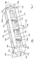
- Fig. 1 shows a Coriolis mass flowmeter 1 with a single, straight Measuring tube 2.
- the measuring tube 2 is manufactured in one piece, but functionally in an inlet and an outlet side tube extension 14, 16 and the intermediate one Measuring section, limited by a Meßorderneinlassquerterrorisms simulation 4 and a Meßordernauslassquerrough Structure 6, divided.
- a central axis 8 of the measuring tube 2 is fixed.
- the central axis 8 coincides here the rotational symmetry axis of the measuring tube 2 together.
- At the pipe extensions14, 16 are the flanges 18, 18a for integration of the measuring device 1 in a process piping system appropriate.
- the attachment 20 is a rotationally symmetrical Hollow body composed of three hollow cylinders, having a first, inlet side, a second, outlet side and a third, middle portion 22, 24, 26 of the Attachment 20 represent. Its rotational symmetry axis coincides with the central axis 8 of the measuring tube 2 together.
- the connection between the middle section 26 and the inlet and outlet side sections 22, 24 is made at transition points 28, 30 by welded plates.
- the inner radii r 1 , r 2 of the inlet or outlet side sections 22, 24 are smaller than the inner radius r 3 of the middle section 26.
- the wall thickness t 3 of the central portion 26, however, is greater than the wall thicknesses t 1 , t 2 of the inlet or outlet-side sections 22, 24th
- the measuring tube 2 can, as is customary in the prior art, made of metal, for example titanium, consist.
- the attachment 20 may be made of metal. It is at the inlet or outlet-side ends 10, 12 of the measuring section welded to the measuring tube.
- an exciter assembly 40 On the inner wall of the middle section cylinder 26 is an exciter assembly 40 attached, which is in operative connection with the measuring tube 2 and through which the Measuring tube 2 in coupled bending / torsional vibrations can be displaced.
- the exciter arrangement For example, as previously suggested, one or more may be suitable arranged, by alternating current-carrying coils arranged therein movable, comprising anchors connected to the measuring tube. According to the AC frequency, the armature or the periodically pushed out of the coil and pulled back into the coil, which then causes the measuring tube 2 to bending vibrations is stimulated.
- eccentric masses are attached to specific locations or the measuring tube itself has an inhomogeneous mass distribution, couples to the bending vibration a torsional vibration, so that in total by the exciter assembly 40 the Measuring tube 2 is offset in a coupled bending and torsional vibration.
- the measuring tube 2 through the exciter arrangement 40 are first excited to torsional vibrations, to which then by means of eccentric Boom masses or inhomogeneous mass distribution in the measuring tube. 2 Coupling bending vibrations, so that in turn by the exciter assembly 40 the Measuring tube 2 is excited to coupled bending and torsional vibrations.
- the torsional vibration mode of the attachment 20 can be adjusted in terms of their frequency and phase relation to the torsional vibration mode of the measuring tube 2 by a suitable determination of the following parameters: the ratio of r 3 to r 2 and r 3 to r 1 , the distances of the transition points 28, 30th from the inlet and outlet ends of the measuring section 10, 12 and the wall thicknesses t 3 , t 1 , t 2 . If suitably selected, the torsional vibration mode of the attachment 20 then has the same frequency, but opposite phase to the torsional vibration mode of the measuring tube, so that then occurring at the inlet or outlet ends of the measuring section 10, 12 torsional moment of the measuring tube M tR opposite equal to that there occurring torsional moment M tA of the attachment 20 is. Both torques compensate each other, the meter 1 is very well balanced at the inlet and outlet ends of the measuring section 10, 12.
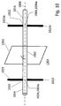
- Fig. 9 illustrates the operation of torsional moment compensation on an analogy example with linearly coupled spring-mass systems.
- the measuring tube corresponds in such an analogy consideration of a mass M R , which is coupled via a spring F RF to the flanges.
- the flanges are in the Analogiebetrachtung a mass M F. , Which couple via another spring F FU to the environment, so the process piping into which the meter is installed.
- the attachment can be considered as a mass M A (namely, the middle portion 20), which is also coupled to the flanges via a spring F AF (namely, the first and second sections). If now the mass M R representing the measuring tube is set in vibration, the spring coupling via F RF and F AF causes both the mass M F representing the flanges and the mass M A representing the attachment to vibrate.
- sensors 42, 42a are mounted for detecting the tube vibration.
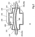
- Fig. 2 shows an alternative embodiment of a mass flow meter according to the invention 1a. Same, similar or similar elements or assemblies of the example of FIG. 2 bear the references increased by 200 as in FIG.
- the measuring tube 202 is between the inlet and outlet ends 210, 212 of the Measuring section slightly bent.
- a slightly curved measuring tube has a complete opposite straight measuring tube the advantage; that with temperature fluctuations Length changes of the measuring tube a length compensation to reduce the emergence tension in the measuring tube is possible.
- An attachment 220 is connected to the measuring tube 202, so that the attachment 220 the Measuring tube 202 in the area of the measuring section surrounds all sides.
- the attachment 220 is a 2-count rotationally symmetrical hollow body, composed of three hollow blocks, the a first, inlet side, second, outlet side and third, middle Part section 222, 224, 226 of the attachment 220 represent. Its rotational symmetry axis coincides with the central axis 208 of the measuring tube 202.
- connection between the middle section 226 and the inlet and outlet side Subsections 222, 224 is welded at transition points 228, 230 by Plates made.
- the Torsionsmomentenkompensation takes place otherwise analogous to that described in Fig. 1 Recordable.
- the inlet and outlet side sections 222, 224 act as torsion springs with a rectangular cross-section, and the central portion 226th acts as a mass with a rectangular cross-section. But apart from the cross-sectional shape are the relationships described in Fig. 1 to the example 2 analog transferable.
- a pathogen assembly is mounted, but not shown here for the sake of clarity.
- a pathogen assembly is mounted, but not shown here for the sake of clarity.
- the measuring tube sensors for receiving the vibration signals, also for reasons of clarity, a presentation was omitted here.
- exciter arrangement and sensors are mounted in a similar manner as shown in FIG.
- FIG. 3 shows a further alternative embodiment of a mass flowmeter according to the invention 301. Same, similar or similar elements or Assemblies of the example of FIG. 3 bear the reference numbers increased by 300 as in FIG. 1
- Fig. 3 shows a Coriolis mass flowmeter 301 with a single, even Measuring tube 302.
- the measuring tube 302 is made of one piece, but functional in one inlet and outlet pipe extensions 314, 316 and the intermediate one Measuring section, limited by a Meßorderneinlassquerterrorisms constitutional 304 and a Meßordernauslassquerrough composition 306 divided.
- a central axis 308 of the measuring tube 302 is fixed.
- the central axis 308 coincides here with the rotational symmetry axis of the measuring tube 302.
- To the Pipe extensions 314, 316 are the flanges 318, 318a for incorporating the meter 301 mounted in a process piping system.
- the attachment 320 is a rotationally symmetrical hollow body with a first, inlet-side, second, outlet-side and third, middle section 322, 324, 326. Its rotational symmetry axis 307 is parallel to the central axis 308 of the measuring tube 302, but does not coincide with her but runs at a distance to the central axis 308 of the measuring tube 302.
- the attachment 320 is made of metal and is manufactured for example by casting. Between the central portion 326 and the inlet and outlet side sections 322, 328 transition parts 328, 330 are formed with. The surface of the Attachment 320 shows a continuous transition between the three sections with correspondingly concave and convex shaped transition points.
- a rigid connection between the measuring tube 302 and the attachment 320 is through Welding each rigid plate 311, 313 inlet and outlet on the measuring tube 302 and welding the attachment 320 to the plates 311, 313 realized.
- the typical mean inner radii r 1 , r 2 of the inlet or outlet-side partial sections 322, 324 are smaller than the typical mean inner radius r 3 of the central partial section 326.
- the wall thickness t 3 of the central partial section 326 is greater than the wall thicknesses t 1 , t 2 of the inlet and outlet side sections 322, 324th
- the torsional vibration mode of the attachment 320 can be adjusted in terms of their frequency and phase relation to the torsional vibration mode of the measuring tube 302 by a suitable determination of the following parameters: the ratio of r 3 to r 2 and r 3 to r 1 , the distances of the transition points 328, 330th from the inlet and outlet ends of the measuring section 310, 312 or the connecting plates 311, 313 and the wall thicknesses t 3 , t 1 , t 2 .
- the torsional vibration mode of the attachment 320 then has the same frequency but opposite phase to the torsional vibration mode of the measuring tube 302, so that then the torsional moment of the measuring tube M tR occurring at the inlet or outlet ends of the measuring section 310, 312 is opposite is equal to the torsional moment occurring there of the attachment 20, M tA . Both torsional moments compensate each other, the measuring device 301 is very well balanced at the inlet or outlet ends of the measuring section 310, 312.
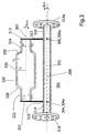
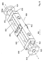
- FIG. 4 shows a further alternative embodiment of a mass flowmeter according to the invention 401. Identical, similar or similar elements or Assemblies of the example of FIG. 4 bear the reference numbers increased by 400 as in FIG. 1
- the measuring tube 402 is made of one piece, but functional in one inlet and outlet pipe extensions 414, 416 and the intermediate one Measuring section, limited by a Meßorderneinlassquerterrorisms simulation 404 and a Meßordernauslassquerrough response 406 divided.
- a central axis 408 of the measuring tube 402 is fixed.
- the central axis 408 coincides here with the rotational symmetry axis of the measuring tube 402.
- To the Pipe extensions 414, 416 are the flanges for incorporating the meter 401 attachable in a process piping system. The flanges are not shown in FIG. 4.
- an attachment 420 is connected, so that the attachment 420 the Measuring tube 402 in the area of the measuring section surrounds all sides.
- the attachment 420 is a rotationally symmetrical body, composed of three partial bodies 422, 424, 426, the first, inlet-side, second, outlet-side and third, middle Represent part of the attachment 420. Its axis of rotational symmetry falls with the central axis 408 of the measuring tube 402 together.
- the inlet-side and outlet-side sections are each one by means of radial, elongated connecting elements 423 attached to the measuring tube 402 circular ring 422 formed, and the middle section is here a stiff hollow cylinder as Connecting body 420.
- the inlet and outlet side sections the shape of a spoked wheel, wherein the radial elongate connecting elements form the spokes.
- suitable choice of the thickness and shape of the Spokes 423 can be the torsional eigenmode of the attachment 420 set.
- the spoked wheel-shaped sections 422, 424 can, for example, by laser cutting be made from a solid disk.
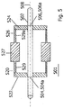
- FIG. 5 shows a further alternative embodiment of a mass flowmeter according to the invention 501. Identical, similar or similar elements or Assemblies of the example of FIG. 5 bear the reference numerals increased by 500 as in FIG. 1
- the middle section 526 is as rotationally symmetrical with respect to the central axis 508 of the measuring tube 502 trained Hollow cylinder executed. Its wall thickness is thickened in its middle part 527, so that there compared to the edge portions 529, 529a higher mass and higher Stiffness arise.
- the edge portions 529, 529a are thin-walled, they act as torsion springs, while the middle part 527 acts as a mass.
- the torsional vibration characteristics of the attachment 520 can be here by varying the extent the edge portions 529, 529 in relation to the central portion 527 and by the amount the thickening of the middle part 527 and adjust its mass.
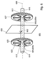
- FIG. 6 shows a further alternative embodiment of a mass flowmeter according to the invention 601. Identical, similar or similar elements or Assemblies of the example of FIG. 6 bear the reference numerals increased by 600 as in FIG. 1
- Fig. 6 shows a Coriolis mass flow meter 601 with a single, straight Measuring tube 602.
- the measuring tube 602 is made of one piece, but functional in one inlet and outlet pipe extensions 614, 616 and the intermediate one Measuring section, limited by a Meßorderneinlassquerterrorisms simulation 604 and a Meßordernauslassquerrough configuration 606, divided.
- a central axis 608 of the measuring tube 602 is fixed.
- the central axis 608 coincides here with the rotational symmetry axis of the measuring tube 602.
- To the Pipe extensions 614, 616 are the flanges 618, 618a for integration of the measuring device 601 attachable to a process piping system.
- the flanges are shown in FIG. 6 not shown.
- each of the attachments 625, 627 With the measuring tube 602 are at the ends of the measuring section an inlet and an outlet side Attachment 625, 627 connected so that each of the attachments 625, 627 the Measuring tube 602 surrounds all sides.
- Mirror symmetry plane 650 of the measuring tube 602 are the two attachments 625, 627 arranged mirror-symmetrically.
- Each of the two attachments 625, 627 is six-fold rotationally symmetric, whose axis of rotational symmetry with the central axis 608 of the measuring tube 602 coincides. They are each one by means of six radial, elongated connecting elements 623 attached to the measuring tube 602 circular ring educated.
- the inlet and outlet side attachments have the Shape of a spoked wheel with six spokes, with the radial elongated Connecting elements form the spokes.
- the thickness of the spokes 623 By suitable choice of the thickness of the spokes 623, the torsional eigenmodes of add-on parts 625, 627 can be adjusted and thus achieve a good balance of the meter, as described above.
- the spoke wheel-shaped attachment parts 625, 627 can be produced, for example, by laser cutting be made from a solid disk. They can also be made of beams, rods or Hohlkörpem be formed.
- the spoke wheel-shaped attachment parts are in each case one on the inlet side, at the beginning of the measuring section, and on the outlet side, at the end of the measuring section, a pair of elongate elements 1023/1023 'attached to the measuring tube 1002, 1023a / 1023a 'reduced.
- Each pair of elongated elements 1023/1023 ', 1023a / 1023a is arranged to have a 2-fold rotational symmetry with respect to the Central axis 1008 has.
- the pairs are elongated Elements 1023/1023 ', 1023a / 1023a' arranged in mirror symmetry.
- the vibration characteristics of pairs of elongated elements 1023/1023 ', 1023a / 1023a' are by length, width, mass and mass distribution within the longitudinal extent Adjustable elements.
- at the free ends of the elongated Elements 1023/1023 ', 1023a / 1023a' are additionally fitted with adjusting materials be.
- FIG. 7 shows a further alternative embodiment of a mass flowmeter according to the invention 701. Same, similar or similar elements or Assemblies of the example of FIG. 7 bear the reference numbers increased by 700 as in FIG. 1
- Fig. 7 shows a Coriolis mass flow meter 701 with a single, straight Measuring tube 702.
- the central axis 708 of the measuring tube 702 coincides here with the rotational symmetry axis of the measuring tube 702 together.
- At the inlet and outlet side Ends 710, 712 of the measuring tube 702 are the flanges 718, 718a for integration of the Measuring device 701 mounted in a process piping system.
- the measuring section extends here over the entire length of the measuring tube between the flanges 718, 718a.
- the measuring tube 702 is a with respect to its rotational symmetry axis 4-fold rotationally symmetrical Attachment 720 connected so that the attachment 720, the measuring tube and so that here the measuring section 702 surrounds all sides.
- the attachment 720 includes a first, inlet side, a second, outlet side and a third, middle portion 722, 724, 726. Its rotational symmetry axis coincides with the central axis of the Measuring tube 702 together.
- the first, inlet-side and second, outlet-side partial sections 722, 724 are formed by thin-walled hollow cylinder.
- the third, middle section 726 is a multi-part composite body, the four-fold rotationally symmetrical to the central axis 708 of the measuring tube is executed. This is shaped like a cuboid, with approximately square end plates 750, 750a and four forming the longitudinal edges of the cuboid, Parallel to the measuring tube 702 extending, connecting elements 752, 754, 756, 758 in the shape also cuboid longitudinal beams.
- the Stim plates 750, 750a have centrically arranged round holes for the passage of the measuring tube.
- the first and second sections are on the end plates 750, 750a forming hollow cylinder 722, 724 welded, they could also be soldered or be connected by another connection technique.
- the cuboid Longitudinal beams 752, 754, 756, 758 are mechanically fastened to the plates 750, 750a, either welded, soldered or bolted.
- each two adjacent longitudinal beams 752, 754, 756, 758 by perpendicular to the longitudinal direction the longitudinal beams arranged cuboid connecting elements connected, so that in each case a frame-like bracing 772, 770, 774 arises, which is oriented perpendicular to the central axis of the measuring tube.
- the exciter assembly is attached to the two Inlet and outlet braces are the sensors for receiving the Vibration state of the pipe attached.
- the diameter of the hollow cylindrical first and second sections 722, 724 is smaller than the edge length of the square face plates 750, 752.
- the first and second sections 722, 724 act as torsion springs, the third section 726 acts as a mass.
- the frame-like struts 772, 770, 774 is achieved an increased rigidity of the third part of the body with low weight.
- the connecting elements 752, 754, 756, 758 can also be used as profile rails or as Hollow profile bar may be formed.
- the middle part body 726 At the inlet-side corners of the middle part body 726 are cylindrical body 760, 762, 764 screwed as adjustment masses. They will be after the final assembly of the Gauge attached and measured by weight and distance from the middle Part 726 is selected so that the balancing is optimized. Depending on the requirement can be attached to all eight corners Justiermassen, or just - as in the Fig. 7 - at some of the corners.
- the torsional vibration characteristics of the attachment 720 can be adjusted by the geometric properties of the first and second sub-bodies 722, 724 - namely their length, diameter and wall thickness -, by the geometric properties of the central part of the body - in particular by its length and the Edge length of the cuboid - and by the masses of the connecting elements 752, 754, 756, 758 as well as by the additional adjustment masses.
- FIG. 8 shows a further alternative embodiment of a mass flowmeter according to the invention 801. Identical, similar or similar elements or Assemblies of the example of FIG. 8 bear the references increased by 800 as in Fig. 1.
- Fig. 8 shows a Coriolis mass flow meter 801 with a single, straight Measuring tube 802.
- the central axis 808 of the measuring tube 802 falls here with the rotational axis of symmetry the measuring tube 802 together.
- At the inlet and outlet side Ends 810, 812 of the measuring tube 802 are the flanges 818, 818a for the integration of the Measuring instrument 801 mounted in a process piping system.
- the measuring section so the area of the measuring tube, by the interaction between the through the measuring tube flowing medium and the measuring tube wall takes place, extends here over the entire length of the measuring tube between the flanges 818, 818a.
- the measuring tube 802 is a with respect to its rotational symmetry axis 2-fold rotationally symmetrical Attachment 820 connected so that the attachment 820 the measuring tube 802 surrounds all sides.
- the attachment 820 includes a first, inlet side, a second, exhaust side and a third, middle subsection 822, 824, 826. Its rotational symmetry axis coincides with the central axis of the measuring tube 802.
- the first, inlet-side, and second, outlet-side sections 822, 824 are formed by thin-walled hollow cylinder.
- the third, middle section 826 is a multi-part composite body, the 2-toe rotationally symmetric to the central axis 808 of the measuring tube is executed.
- This is shaped like a cuboid, with approximately rectangular end plates 850, 850a and two parallel to the measuring tube 802 extending connecting elements 852, 854 in the shape of elongated plates or hollow bodies.
- the connecting elements 852, 854 are respectively screwed to the narrow sides of the end plates 850, 850a with these. Their height corresponds to the height of the end plates 850, 850a. Total form the end plates 850, 850a together with the connecting elements 852, 854 a rectangular frame.
- the end plates 850, 850a have centrally arranged round holes for implementation of the measuring tube. Inlet and outlet are on the Stimplatten 850, 850a the the first and second sections forming hollow cylinder 822, 824 welded, they could also be soldered.
- the diameter of the hollow cylindrical first and second sections 822, 824 is smaller than the edge length of the square face plates 850, 852.
- the first and second sections 822, 824 act as torsion springs, the third section 826 acts as a mass.
- the torsional vibration characteristics of the attachment 820 can be adjusted by the geometric properties of the first and second sub-bodies 822, 824 - namely their length, diameter and wall thickness -, by the geometric properties of the central part of the body - in particular by its length and the Edge lengths and the ratio of width to height of the cuboid - and by the Masses of the connecting elements 752, 754.
- FIG. 8 is similar to the embodiment according to FIG. 7. It is even easier to manufacture than that. Especially when the connecting elements 852, 854 designed as elongated hollow cuboid can be, the attachment with the vibration characteristics required for optimal balance and still be built small total mass.
- FIG. 11 shows a further alternative embodiment of a mass flowmeter according to the invention 1101. Same, similar or similar elements or assemblies of the example of FIG. 11 carry the reference numbers increased by 1100 as in FIG. 1
- Fig. 11 shows a Coriolis mass flow meter 1101 with a single, even Measuring tube 1102.
- the measuring tube 1102 is made of one piece, but functional into an inlet and an outlet pipe extension 1114, 1116 and the intermediate one Measuring section, limited by a measuring section inlet cross-sectional area 1104 and a Meßordernauslassquerêt Structure 1106 divided.
- 1106a is a central axis 1108 of the measuring tube 1102 set.
- the central axis 1108 coincides here with the rotational symmetry axis of the measuring tube 1102 together.
- At the tube extensions 1114, 1116 are the flanges 1118, 1118a for integrating the meter 1101 in a process piping system attached.
- the attachment 1120 is a rotationally symmetrical Body with a first, inlet side, a second, outlet side and a third, middle subsection 1122, 1124, 1126. Its rotational symmetry axis 1107 is parallel to the central axis 1108 of the measuring tube 1102, but does not fall with it together sondem runs at a distance from the central axis 1108 of the measuring tube 1,102th
- the attachment 1120 is made of metal and is manufactured, for example, by casting. Between the middle section 1126 and the inlet and outlet side Subsections 1122, 1128 transition parts 1128, 1130 are formed with.
- the surface of attachment 1120 shows a continuous transition between the three Subsections with correspondingly concave and convex shaped transition points, wherein the central portion 1126 is convex.
- a rigid connection between the measuring tube 1102 and the attachment 1120 is by welding each a rigid plate 1111, 1113 inlet and outlet side the measuring tube 1102 and welding the fixture 1120 to the plates 1111, 1113 realized.
- the connection points 1110a, 1112a of the attachment 1120 with the measuring tube 1102 lie within the measuring section.
- the compensation part 1180 is more eccentric Trough formed and with the measuring tube 1102 to the input and output 1110, Attached 1112 the measuring section, for example by welding or screws.
- the idea underlying the arrangement according to FIG. 11 is that the part of the Measuring tube, by the at least one compensation part with respect to bending and / or Torsions theory is compensated, and the part, by the attachment in relation is compensated for the torsional moment, can be congruent, or one of both parts encompass the other.
- the larger of the two parts defines the Measuring section.
- the part defined by the compensation part is compensated, the measuring section.
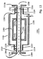
- FIG. 13 shows a further alternative embodiment of a mass flowmeter according to the invention 1301. Same, similar or similar elements or assemblies of the example of FIG. 13 carry the reference numerals increased by 1300 as in Fig. 1.
- Fig. 13 shows a Coriolis mass flow meter 1301 with a single, even Measuring tube 1302.
- the measuring tube 1302 is made of one piece, but functional into an inlet and an outlet pipe extension 1314, 1316 and the intermediate one Measuring section, limited by a measuring section inlet cross-sectional area 1304 and a Meßordernauslassquerêt Structure 1306 divided.
- Centers 1304a, 13066a is a central axis 1308 of the measuring tube 1302 set.
- the central axis 1308 coincides here with the rotational symmetry axis of the measuring tube 1302 together.
- At the tube extensions 1314, 1316 are the flanges 1318, 1318a for the integration of the measuring device 1301 mounted in a process piping system.
- an attachment 1320 is connected, which the measuring tube 1302 surrounds on all sides in the area of the measuring section.
- the attachment 1320 is a rotationally symmetrical Hollow body composed of three hollow cylinders, having a first, inlet side, a second, outlet side and a third, middle portion 1322, 1324, 1326 of the attachment 1320 represent. Its axis of rotational symmetry falls with the central axis 1308 of the measuring tube 1302 together.
- the connection between the middle section 1326 and the inlet and outlet side Subsections 1322, 1324 is welded at transition points 1328, 1330 by Plates made.
- the inner radii r1, r2 of the inlet and outlet side Subsections 1322, 1324 are smaller than the inner radius r3 of the central subsection 1326.
- the wall thickness t3 of the middle section 1326 is larger as the wall thicknesses t1, t2 of the inlet-side and outlet-side partial sections 1322, 1324, respectively.
- the measuring tube 1302 as usual in the art, made of metal, for example Titanium, insist. Also, the attachment 1320 may be made of metal. It is at the inlet or outlet-side ends 1310, 1312 of the measuring section welded to the measuring tube.
- the compensation part is designed as a tube and attached to the measuring tube 1302 at joints 1310a and 1310b, for example by welding or screws.
- the connection points 1310a, 1312a of the compensation part 1380 with the measuring tube 1302 are thus within the Measuring distance.
- the idea underlying the arrangement according to FIG. 13 is that the part of the Measuring tube, by the at least one compensation part with respect to bending and / or Torsions theory is compensated, and the part, by the attachment in relation is compensated for the torsional moment, can be congruent, or one of both parts encompass the other.
- the larger of the two parts defines the Measuring section.
- the part compensated by the attachment part is the measuring distance.
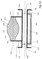
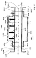
- FIG. 14 A further possible embodiment of this is shown in FIG. 14 in the invention Mass flowmeter 1401. Same, similar or similar elements or assemblies of the example of FIG. 14 carry the reference numbers increased by 1400 as in Fig. 1.
- Fig. 14 shows a Coriolis mass flow meter 1401 with a single, straight Measuring tube 1402.
- the measuring tube 1402 is made in one piece, but functional into an inlet and an outlet tube extension 1414, 1416 and the intermediate one Measuring section, limited by a measuring section inlet cross-sectional area 1404 and a Meßordernauslassqueritess response 1406 divided.
- Centers 1404a, 1406a is a central axis 1408 of the measuring tube 1402 set.
- the central axis 1408 falls here with the axis of rotational symmetry of the measuring tube 1402 together.
- At the tube extensions 1414, 1416 are the flanges 1418, 1418a for integrating the measuring device 1401 mounted in a process piping system.
- the attachment 1420 is a rotationally symmetrical Hollow body composed of three hollow cylinders, having a first, inlet side, a second, outlet side and a third, middle portion 1422, 1424, 1426 of the attachment 1420 represent. Its axis of rotational symmetry falls with the central axis 1408 of the measuring tube 1402 together.
- the connection between the middle section 1426 and the inlet and outlet side Subsections 1422, 1424 is welded at transition points 1428, 1430 by Plates made.
- the inner radii r1, r2 of the inlet and outlet side Subsections 1422, 1424 are smaller than the inner radius r3 of the middle subsection 1426.
- the wall thickness t3 of the middle section 1426 is larger as the wall thicknesses t1, t2 of the inlet-side and outlet-side partial sections 1422, 1424, respectively.
- the measuring tube 1402 can, as usual in the art, made of metal, for example Titanium, insist. Also, the attachment 1420 may be made of metal. It is at the inlet or outlet-side ends 1410, 1412 of the measuring section welded to the measuring tube.
- four plates 1480a, 1480b, 1480c, 1480d mounted eccentrically relative to the central axis 1408 on the measuring tube. In a previously proposed way they cause the compensation of Bending and / or torsional forces on the measuring tube 1402.
- the plates 1480a, b, c, d are arranged so that they are within the measuring section and within the middle section 1426 of the attachment 1420 lie.
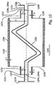
- FIG. 12 shows a further alternative embodiment of a mass flowmeter according to the invention 1201. Same, similar or similar elements or assemblies of the example of FIG. 12 carry reference numbers increased by 1200 as in Fig. 1.
- Fig. 12 shows a Coriolis mass flow meter 1201 having an approximately double S-shape bent measuring tube 1202.
- the measuring tube 1202 is made of one piece, but functionally in an inlet and outlet tube extension 1214, 1216 and the intermediate measurement path, bounded by a measurement path inlet cross-sectional area 1204 and a Meßordernauslassquer songs 1206 divided.
- By their centers 1204a, 12066a is a central axis 1208 of the measuring tube 1202.
- At the tube extensions 1214, 1216 are the flanges 1218, 1218a attached to the integration of the meter 1201 in a process piping system.
- an attachment 1220 is connected, which the measuring tube 1202 surrounds on all sides in the area of the measuring section.
- the attachment 1220 is a rotationally symmetrical Hollow body composed of three hollow cylinders, having a first, inlet side, a second, outlet side and a third, middle portion 1222, 1224, 1226 of the attachment 1220 represent. Its axis of rotational symmetry falls with the central axis 1208 of the measuring tube 1202 together.
- the connection between the middle section 1226 and the inlet and outlet side Subsections 1222, 1224 is welded at transition points 1228, 1230 by Plates made.
- the inner radii r1, r2 of the inlet and outlet side Subsections 1222, 1224 are smaller than the inner radius r3 of the central subsection 1226.
- the wall thickness t3 of the middle section 1226 is larger as the wall thicknesses t1, t2 of the inlet-side and outlet-side partial sections 1222, 1224, respectively.
- the measuring tube 1202 can, as usual in the art, made of metal, for example Titanium, insist. Also, the attachment 1220 may be made of metal. It is at the inlet or outlet-side ends 1210, 1212 of the measuring section welded to the measuring tube.
- FIG. 12 is an example of how the compensation of the Torsionsmomente means of an attachment according to the invention even with complex bent Measuring tubes is possible.
- the measuring tube could also be U-shaped, Be V-shaped or spiral bebogen.
- FIGS. 1 to 14 are not exhaustive Selection of possible embodiments of a Coriolis mass flow meter according to the invention Other combinations of different aspects of the in the exemplary embodiments shown Coriolis mass flow meters are intended also be covered by the present application.
Landscapes
- Physics & Mathematics (AREA)
- Fluid Mechanics (AREA)
- General Physics & Mathematics (AREA)
- Measuring Volume Flow (AREA)
Abstract
Description
- fester symmetrischer Einbau
Durch spezielle Einbauvorschriften soll hier sichergestellt werden, dass der CMD wohldefiniert an die Umgebung koppelt. Die Geräte selbst haben eine grosse Masse. Nachteile sind erhöhte Einbaukosten, schwere Befestigungen und eine grosse Empfindlichkeit des Gerätes gegen äussere Einflüsse (z. B. geringe Nullpunktsstabilität). - Biege-Gegenschwinger
Die Vibration des Messrohres wird durch Anbringen eines Biege-Gegenschwingers kompensiert. Dieser schwingt gegenphasig zum Messrohr und eliminiert im Idealfall die Oszillationsbewegung des Schwerpunktes. Dann koppeln keine Kräfte am Rand aus. Eine solche Kompensation funktioniert im Allgemeinen nur für eine Dichte des Fluides, bei anderen Dichten stimmen die Massenverhältnisse von Messrohr und Gegenschwinger nicht mehr und die Kopplung an die Umgebung steigt stark an. Dann sinkt auch die Messgenauigkeit. - Torsionsgegenschwinger
Anstelle eines Biege-Gegenschwingers wird durch exzentrisches Anbringen von Massen die Biegeeigenschwingung an eine Torsionsschwingung des Rohres gekoppelt. Es wurde vorgeschlagen, dies durch das Anbringen einer Anzahl von Auslegermassen am Messrohr zu erreichen, deren Schwerpunkte in einer gemeinsamen, senkrecht zur Biegeschwingungsebene durch die Längsachse des Messrohres verlaufenden Ebene, jedoch im allgemeinen nicht auf dieser Längsachse liegen. Eine alternative Möglichkeit ist das Anbringen eines steifen exzentrischen Troges, wie in der US 2002/0117010A1 gezeigt. Da beide Schwingungsmoden (die Biege- und die Torsionsschwingungsmode) in ähnlicher Weise von der Fluidmasse beeinflusst werden, zeigt sich, dass man Randkräfte, d.h. Biege- und Torsionskräfte - über einen großen Dichtebereich kompensieren kann. Der balancierte Teil des Messrohres wird im folgenden auch als Messstrecke bezeichnet. Die Messdaten sollen nur innerhalb der solcherart balancierten Messstrecke aufgenommen werden.
- Fig. 1
- eine erste Ausführungsform der Erfindung, bei der das Anbauteil drei Rohrstücke umfasst,
- Fig. 2
- eine zweite Ausführungsform der Erfindung, bei der das Anbauteil drei Hohlquader umfasst,
- Fig. 3
- eine dritte Ausführungsform der Erfindung, bei der das Anbauteil ein achssymmetrischer Körper mit kontinuierlichen Übergängen zwischen Zonen unterschiedlichen Querschnitts ist,
- Fig. 4
- eine vierte Ausführungsform der Erfindung, bei der das Anbauteil zwei durch einen Zylindermantel verbundene, speichenradförmige Ringkörper umfasst,
- Fig. 5
- eine fünfte Ausführungsform der Erfindung, bei der das Anbauteil zwei verbundene Scheiben und schwere Massen in der Mitte umfasst,
- Fig. 6
- eine sechste Ausführungsform, bei der zwei speichenradförmige Anbauteile an dem Messrohr angebracht sind,
- Fig. 7
- eine siebte Ausführungsform, bei der das Anbauteil vier an senkrecht zur Messrohrachse verlaufenden Platten gehaltene Hohlkörper umfasst,
- Fig. 8
- eine achte Ausführungsform, bei der das Anbauteil zwei an senkrecht zur Messrohrachse verlaufenden Platten gehaltene Hohlkörper umfasst,
- Fig. 9
- ein vereinfachtes Feder-Masse-Modell zur Veranschaulichung der Funktionsweise,
- Fig. 10
- eine neunte Ausführungsform, bei der zwei Paare längserstreckter Elemente als Anbauteile an dem Messrohr angebracht sind,
- Fig. 11
- eine zehnte Ausführungsform, bei der an dem Messrohr neben dem Anbauteil noch ein weiteres Kompensationsteil angebracht ist,
- Fig. 12
- eine elfte Ausführungsform, bei der das Messrohr S-förmig gebogen ist,
- Fig. 13
- eine zwölfte Ausführungsform, bei der an dem Messrohr neben dem Anbauteil ebenfalls ein weiteres Kompensationsteil angebracht ist, und
- Fig. 14
- eine dreizehnte Ausführungsform, bei der an dem Messrohr vier exzentrische Massen als weitere Kompensationsteile angebracht sind.
Claims (52)
- Coriolis - Massendurchflussmessgerät mit einem in gekoppelten Biege- und Torsionsmoden schwingenden Messrohr (2), dadurch gekennzeichnet, dass ein bezüglich einer Rotationssymmetrieachse drehsymmetrisch ausgebildetes, in Torsionsschwingungen gleicher Frequenz aber entgegengesetzter Phasenlage zu den Torsionsschwingungsmoden des Messrohres(2) versetzbares Anbauteil (20) mechanisch mit dem Messrohr (2) verbunden ist und die Rotationssymmetrieachse des Anbauteils parallel zu der durch die Mittelpunkte (4a, 6a) der Messstreckeneinlass- und Messstreckenauslassquerschnittsflächen (4, 6) festgelegten Geraden (8) (Zentralachse) verläuft oder mit dieser zusammenfällt.
- Coriolis-Massendurchflussmessgerät nach Anspruch 1, dadurch gekennzeichnet, dass das Anbauteil spiegelsymmetrisch bezüglich einer senkrecht zu der Rotationssymmetrieachse orientierten und die Zentralachse in der Mitte der Messstrecke schneidenden Symmetrieebene ist.
- Coriolis-Massendurchflussmessgerät nach einem der vorigen Ansprüche, dadurch gekennzeichnet, dass wenigstens ein weiteres Kompensationsteil zur Kompensation von Biege- und/oder Torsionskräften an dem Messrohr angebracht ist.
- Coriolis-Massendurchflussmessgerät nach einem der vorigen Ansprüche, dadurch gekennzeichnet, dass das Anbauteil einlass- und auslassseitig mit dem Messrohr verbunden ist.
- Coriolis-Massendurchflussmessgerät nach Anspruch 4, dadurch gekennzeichnet, dass das Anbauteil an den einlass- und auslassseitigen Messstreckenenden mit dem Messrohr verbunden ist.
- Coriolis-Massendurchflussmessgerät nach Anspruch 4, dadurch gekennzeichnet, dass das Anbauteil innerhalb der Messstrecke mit dem Messrohr verbunden ist.
- Coriolis-Massendurchflussmessgerät nach einem der vorigen Ansprüche, dadurch gekennzeichnet, dass das weitere Kompensationsteil innerhalb der Messstrecke an dem Messrohr angebracht ist.
- Coriolis-Massendurchflussmessgerät nach einem der vorigen Ansprüche, dadurch gekennzeichnet, dass das Anbauteil das Messrohr zumindest im Bereich der Messstrecke umhüllt.
- Coriolis- Massendurchflussmessgerät nach einem der Ansprüche 1 bis 4, dadurch gekennzeichnet, dass das Anbauteil außerhalb des Messrohres angeornet, aber mit diesem verbunden ist.
- Coriolis-Massendurchflussmessgerät nach einem der vorigen Ansprüche, dadurch gekennzeichnet, dass das Massendurchflussmessgerät ein einziges, gerades Messrohr umfasst.
- Coriolis-Massendurchflussmessgerät nach einem der Ansprüche 1 bis 9, dadurch gekennzeichnet, dass das Messrohr ein gebogenes Messrohr umfasst.
- Coriolis-Massendurchflussmessgerät nach Anspruch 11, dadurch gekennzeichnet, dass das Messrohr U- oder S- oder V-förmig gebogen ist.
- Coriolis-Massendurchflussmessgerät nach einem der vorherigen Ansprüche, dadurch gekennzeichnet, dass das Anbauteil wenigstens einen ersten, einlassseitigen, einen zweiten, auslassseitigen und einen dritten, mittleren Teilabschnitt umfasst, wobei jeder Teilabschnitt bezüglich der Rotationssymmetrieachse drehsymmetrisch ausgebildet ist.
- Coriolis-Massendurchflussmessgerät nach Anspruch 13, dadurch gekennzeichnet, dass die Übergänge zwischen den Teilabschnitten stufenartig ausgebildet sind.
- Coriolis-Massendurchflussmessgerät nach Anspruch 13, dadurch gekennzeichnet, dass die Übergänge zwischen den Teilabschnitten kontinuierlich ausgebildet sind.
- Coriolis-Massendurchflussmessgerät nach einem der vorherigen Ansprüche, dadurch gekennzeichnet, dass das Torsionsflächenmoment des mittleren Teilabschnitts betragsmäßig größer ist als die Torsionsflächenmomente der einlassund auslassseitigen Teilabschnitte.
- Coriolis-Massendurchflussmessgerät nach Anspruch 16, dadurch gekennzeichnet, dass die einlass- und auslassseitigen Teilabschnitte als Drehfedern und der mittlere Teilabschnitt als träge Masse wirken.
- Coriolis-Massendurchflussmessgerät nach Anspruch 17, dadurch gekennzeichnet, dass die Frequenz und Phasenlage der Torsionsschwingungsmode des Anbauteils durch das Verhältnis der Beträge der Torsionsflächenmomente des mittleren und der einlass- sowie auslassseitigen Teilabschnitte sowie durch die Lage der Übergänge zwischen dem mittleren und den einlass- bzw. auslassseitigen Teilabschnitten einstellbar sind.
- Coriolis-Massendurchflussmessgerät nach einem der vorhergehenden Ansprüche, dadurch gekennzeichnet, dass das Anbauteil in Torsionsschwingungen gleicher Frequenz aber entgegengesetzter Phasenlage zu den Torsionsschwingungen des Messrohres versetzt ist.
- Coriolis-Massendurchflussmessgerät nach einem der vorhergehenden Ansprüche, dadurch gekennzeichnet, dass wenigstens ein Teilabschnitt des Anbauteils ein Hohlkörper ist.
- Coriolis-Massendurchflussmessgerät nach einem der vorigen Ansprüche, dadurch gekennzeichnet, dass wenigstens ein Teilabschnitt des Anbauteils ein dünnwandiger Hohlkörper ist.
- Coriolis-Massendurchflussmessgerät nach Anspruch 21, dadurch gekennzeichnet, dass der dünnwandige Hohlkörper ein Hohlzylinder oder ein Hohlquader ist.
- Coriolis-Massendurchflussmessgerät nach einem der vorhergehenden Ansprüche, dadurch gekennzeichnet, dass wenigstens ein Teilabschnitt des Anbauteils ein mehrteilig zusammengesetzter Körper ist.
- Coriolis-Massendurchflussmessgerät nach Anspruch 23, dadurch gekennzeichnet, dass der mehrteilig zusammengesetzte Körper parallel zur Rotationssymmetrieachse verlaufende und an senkrecht zur Messrohrachse verlaufenden Platten gehaltene, längserstreckte Bauelemente umfasst.
- Coriolis-Massendurchflussmessgerät nach Anspruch 24, dadurch gekennzeichnet, dass die längserstreckten Bauelemente Profilschienen sind.
- Coriolis-Massendurchflussmesser nach Anspruch 24, dadurch gekennzeichnet, dass die längserstreckten Bauelemente Hohlkörper sind.
- Coriolis-Massendurchflussmessgerät nach einem der vorhergehenden Ansprüche, dadurch gekennzeichnet, dass die einlassseitigen und auslassseitigen Teilabschnitte je einen mittels radialer, längserstreckter Verbindungselemente an dem Messrohr angebrachten Kreisring und der mittlere Teilabschnitt einen steifen Verbindungskörper umfassen.
- Coriolis-Massendurchflussmessgerät nach Anspruch 27, dadurch gekennzeichnet, dass der steife Verbindungskörper ein Hohlkörper ist.
- Coriolis-Massendurchflussmessgerät nach Anspruch 28, dadurch gekennzeichnet, dass der Hohlkörper ein Hohlzylinder ist.
- Coriolis-Massendurchflussmessgerät nach Anspruch 28, dadurch gekennzeichnet, dass der Hohlkörper ein Hohlquader ist.
- CorioJis-Massendurchflussmessgerät nach Anspruch 27, dadurch gekennzeichnet, dass der steife Verbindungskörper ein mehrteilig zusammengesetzter Körper ist.
- Coriolis-Massendurchflussmessgerät nach Anspruch 31, dadurch gekennzeichnet, dass der steife Verbindungskörper parallel zur Rotationssymmetrieachse verlaufende längserstreckte Bauelemente umfasst.
- Coriolis-Massendurchflussmessgerät nach Anspruch 32, dadurch gekennzeichnet, dass die längserstreckten Bauelemente Profilschienen oder Balken oder Stäbe sind.
- Coriolis-Massendurchflussmessgerät nach Anspruch 32, dadurch gekennzeichnet, dass die längserstreckten Bauelemente Hohlkörper sind.
- Coriolis-Massendurchflussmessgerät nach einem der vorhergehenden Ansprüche, dadurch gekennzeichnet, dass die Torsionsschwingungseigenschaften des Anbauteils über die Dimensionierung der längserstreckten Verbindungselemente einstellbar sind.
- Coriolis-Massendurchflussmessgerät nach einem der vorhergehenden Ansprüche, dadurch gekennzeichnet, dass die Erregeranordnung an dem Anbauteil angebracht ist.
- Coriolis-Massendurchflussmessgerät nach einem der vorhergehenden Ansprüche, dadurch gekennzeichnet, dass Sensoren zur Schwingungserfassung an dem Anbauteil angebracht sind.
- Coriolis-Massendurchflussmessgerät nach einem der vorhergehenden Ansprüche, dadurch gekennzeichnet, dass an dem Anbauteil Justierelemente zur nachträglichen Trimmung angebracht sind.
- Coriolis-Massendurchflussmessgerät nach einem der vorigen Ansprüche, dadurch gekennzeichnet, dass das Anbauteil je eine erste, einlassseitig und eine zweite, auslassseitig an dem Messrohr angebrachte starre Platte umfasst, die mittels eines tordierbaren Verbindungskörpers miteinander verbunden sind.
- Coriolis-Massendurchflussmessgerät nach Anspruch 39, dadurch gekennzeichnet, dass der tordierbare Verbindungskörper ein Hohlkörper ist.
- Coriolis-Massendurchflussmessgerät nach Anspruch 40, dadurch gekennzeichnet, dass der Hohlkörper ein Hohlzylinder oder ein Hohlquader ist.
- Coriolis-Massendurchflussmessgerät nach Anspruch 39, dadurch gekennzeichnet, dass der tordierbare Verbindungskörper ein mehrteilig zusammengesetzter Körper ist.
- Coriolis-Massendurchflussmessgerät nach Anspruch 42, dadurch gekennzeichnet, dass der tordierbare Verbindungskörper aus parallel zur Messrohrachse verlaufenden längserstreckten Bauelementen gebildet ist.
- Coriolis-Massendurchflussmessgerät nach Anspruch 43, dadurch gekennzeichnet, dass die längserstreckten Bauelemente Profilschienen oder Balken oder Stäbe sind.
- Coriolis-Massendurchflussmessgerät nach Anspruch 44, dadurch gekennzeichnet, dass die längserstreckten Bauelemente Hohlkörper sind.
- Coriolis - Massendurchflussmessgerät mit einem in gekoppelten Biege- und Torsionsmoden schwingenden Messrohr, dadurch gekennzeichnet, dass wenigstens zwei bezüglich einer gemeinsamen Rotationssymmetrieachse drehsymmetrisch ausgebildete, in Torsionsschwingungen gleicher Frequenz aber entgegengesetzter Phasenlage zu den Torsionsschwingungsmoden des Messrohres versetzbare Anbauteile mechanisch mit dem Messrohr verbunden sind und die gemeinsame Rotationssymmetrieachse der Anbauteile parallel zu der durch die Mittelpunkte der Messstreckeneinlass- und Messstreckenauslassquerschnittsflächen festgelegten Geraden (Zentralachse) verläuft oder mit dieser zusammenfällt.
- Coriolis-Massendurchflussmessgerät nach Anspruch 46, dadurch gekennzeichnet, dass an dem einlass - bzw. auslassseitigen Messstreckenende je ein einlass- bzw. auslassseitiges, kreisringartiges Anbauteil mittels radialer, längserstreckter Verbindungselemente an dem Messrohr angebracht ist.
- Coriolis-Massendurchflussmessgerät nach Anspruch 47, dadurch gekennzeichnet, dass die längserstreckten Verbindungselemente Stäbe, Balken oder Rohre sind.
- Coriolis-Massendurchflussmessgerät nach Anspruch 48, dadurch gekennzeichnet, dass die Torsionsschwingungseigenschaften des einlass- bzw. auslassseitigen Anbauteils über die Dimensionierung der längserstreckten Verbindungselemente einstellbar sind.
- Coriolis-Massendurchflussmessgerät nach Anspruch 46, dadurch gekennzeichnet, dass die Anbauteile Paare längserstreckter Elemente 1(023/1023'), (1023a/1023a') sind.
- Coriolis-Massendurchflussmessgerät nach einem der vorigen Ansprüche, dadurch gekennzeichnet, dass das weitere Kompensationsteil ein exzentrisch bezüglich der Zentralachse angebrachter, steifer Trog oder ein Kompensationsrohr ist.
- Coriolis-Massendurchflussmessgerät nach einem der vorigen Ansprüche, dadurch gekennzeichnet, dass exzentrisch bezüglich der Zentralachse angebrachte Auslegermassen als weitere Kompensationsteile an dem Messrohr angebracht sind
Applications Claiming Priority (2)
| Application Number | Priority Date | Filing Date | Title |
|---|---|---|---|
| DE10351311A DE10351311B3 (de) | 2003-10-31 | 2003-10-31 | Coriolis-Massendurchflussmessgerät |
| DE10351311 | 2003-10-31 |
Publications (2)
| Publication Number | Publication Date |
|---|---|
| EP1528374A1 true EP1528374A1 (de) | 2005-05-04 |
| EP1528374B1 EP1528374B1 (de) | 2011-01-19 |
Family
ID=34399665
Family Applications (1)
| Application Number | Title | Priority Date | Filing Date |
|---|---|---|---|
| EP04023641A Expired - Lifetime EP1528374B1 (de) | 2003-10-31 | 2004-10-05 | Coriolis-Massendurchflussmessgerät |
Country Status (7)
| Country | Link |
|---|---|
| US (1) | US7213470B2 (de) |
| EP (1) | EP1528374B1 (de) |
| JP (1) | JP2005134393A (de) |
| CN (1) | CN100405024C (de) |
| AT (1) | ATE496285T1 (de) |
| CA (1) | CA2486321A1 (de) |
| DE (2) | DE10351311B3 (de) |
Cited By (7)
| Publication number | Priority date | Publication date | Assignee | Title |
|---|---|---|---|---|
| DE102005042677A1 (de) * | 2005-08-27 | 2007-03-08 | Abb Patent Gmbh | Coriolis-Massendurchfluss-Aufnehmer |
| WO2007074015A1 (de) * | 2005-12-22 | 2007-07-05 | Endress+Hauser Flowtec Ag | MEßWANDLER VOM VIBRATIONSTYP |
| US7325462B2 (en) | 2005-12-22 | 2008-02-05 | Endress + Hauser Flowtec Ag | Measuring transducer of vibration-type |
| RU2413183C2 (ru) * | 2006-05-01 | 2011-02-27 | Майкро Моушн, Инк. | Уравновешивающая конструкция для расходомера кориолиса с одной криволинейной трубкой |
| WO2012136490A1 (de) * | 2011-04-07 | 2012-10-11 | Endress+Hauser Flowtec Ag | Frequenzabgleichsverfahren für eine rohranordnung |
| WO2012136489A1 (de) * | 2011-04-07 | 2012-10-11 | Endress+Hauser Flowtec Ag | Verfahren zum trimmen eines rohrs |
| EP2252865B1 (de) * | 2008-02-20 | 2020-09-30 | Micro Motion, Inc. | Durchflussmesser vom vibrationstyp und verfahren zur austarierung eines durchflussmessers vom vibrationstyp |
Families Citing this family (35)
| Publication number | Priority date | Publication date | Assignee | Title |
|---|---|---|---|---|
| DE102004060420A1 (de) * | 2004-12-14 | 2006-06-29 | Krohne Ag | Coriolis-Massendurchflußmeßgerät |
| US7475603B2 (en) | 2005-11-15 | 2009-01-13 | Endress + Hauser Flowtec Ag | Measurement transducer of vibration-type |
| US7490521B2 (en) | 2005-11-15 | 2009-02-17 | Endress + Hauser Flowtec Ag | Measurement transducer of vibration type |
| US7472607B2 (en) | 2005-11-15 | 2009-01-06 | Endress + Hauser Flowtec Ag | Measurement transducer of vibration type |
| DE102005054855A1 (de) * | 2005-11-15 | 2007-05-16 | Flowtec Ag | Meßwandler vom Vibrationstyp |
| DE102005062007A1 (de) * | 2005-12-22 | 2007-06-28 | Endress + Hauser Flowtec Ag | Meßwandler vom Vibrationstyp |
| DE102005062004A1 (de) * | 2005-12-22 | 2007-06-28 | Endress + Hauser Flowtec Ag | Meßwandler vom Vibrationstyp |
| DE102006062185A1 (de) * | 2006-12-22 | 2008-06-26 | Endress + Hauser Flowtec Ag | Meßwandler vom Vibrationstyp |
| DE102006062220A1 (de) * | 2006-12-22 | 2008-06-26 | Endress + Hauser Flowtec Ag | Meßwandler vom Vibrationstyp |
| DE102006062219A1 (de) * | 2006-12-22 | 2008-06-26 | Endress + Hauser Flowtec Ag | Meßwandler vom Vibrationstyp |
| DE102007021099A1 (de) | 2007-05-03 | 2008-11-13 | Endress + Hauser (Deutschland) Ag + Co. Kg | Verfahren zum Inbetriebnehmen und/oder Rekonfigurieren eines programmierbaren Feldmeßgeräts |
| DE102007050686A1 (de) * | 2007-10-22 | 2009-04-23 | Endress + Hauser Flowtec Ag | Meßwandler vom Vibrationstyp |
| DE102007058608A1 (de) | 2007-12-04 | 2009-06-10 | Endress + Hauser Flowtec Ag | Elektrisches Gerät |
| DE102008016235A1 (de) | 2008-03-27 | 2009-10-01 | Endress + Hauser Flowtec Ag | Verfahren zum Betreiben eines auf einer rotierenden Karussell-Abfüllmachine angeordneten Meßgeräts |
| DE102008022373A1 (de) | 2008-05-06 | 2009-11-12 | Endress + Hauser Flowtec Ag | Meßgerät sowie Verfahren zum Überwachen eines Meßgeräts |
| DE102008002215A1 (de) * | 2008-06-04 | 2009-12-10 | Endress + Hauser Flowtec Ag | Vorrichtung zur Bestimmung und/oder Überwachung eines Strömungsparameters |
| DE102008050113A1 (de) | 2008-10-06 | 2010-04-08 | Endress + Hauser Flowtec Ag | In-Line-Meßgerät |
| DE102008050116A1 (de) | 2008-10-06 | 2010-04-08 | Endress + Hauser Flowtec Ag | In-Line-Meßgerät |
| DE102008050115A1 (de) | 2008-10-06 | 2010-04-08 | Endress + Hauser Flowtec Ag | In-Line-Meßgerät |
| CN101858764B (zh) * | 2009-04-07 | 2012-07-18 | 西门子(中国)有限公司 | 科里奥利质量流量计 |
| DE102010018222B4 (de) * | 2010-04-23 | 2012-03-22 | Krohne Ag | Coriolis-Massedurchflussmessgerät |
| DE102010030924A1 (de) | 2010-06-21 | 2011-12-22 | Endress + Hauser Flowtec Ag | Elektronik-Gehäuse für ein elektronisches Gerät bzw. damit gebildetes Gerät |
| DE102011013263B4 (de) * | 2011-03-07 | 2018-02-15 | Krohne Ag | Coriolis-Massedurchflussmessgerät |
| DE102011006971A1 (de) | 2011-04-07 | 2012-10-11 | Endress + Hauser Flowtec Ag | Meßwandler vom Vibrationstyp sowie Verfahren zu dessen Herstellung |
| DE102011076838A1 (de) | 2011-05-31 | 2012-12-06 | Endress + Hauser Flowtec Ag | Meßgerät-Elektronik für ein Meßgerät-Gerät sowie damit gebildetes Meßgerät-Gerät |
| CA3006404C (en) * | 2012-12-17 | 2021-03-02 | Micro Motion, Inc. | Improved case for a vibrating meter |
| WO2014102036A1 (de) * | 2012-12-30 | 2014-07-03 | Endress+Hauser Flowtec Ag | Messwandler vom vibrationstyp sowie damit gebildetes messsystem |
| DE102013102711A1 (de) | 2013-03-18 | 2014-09-18 | Endress + Hauser Flowtec Ag | Meßwandler vom Vibrationstyp sowie damit gebildetes Meßsystem |
| DE102013102708A1 (de) | 2013-03-18 | 2014-09-18 | Endress + Hauser Flowtec Ag | Meßwandler vom Vibrationstyp sowie damit gebildetes Meßsystem |
| US9541429B2 (en) * | 2014-06-02 | 2017-01-10 | University Of Kansas | Systems, methods, and devices for fluid data sensing |
| US10585109B2 (en) * | 2014-06-02 | 2020-03-10 | University Of Kansas | Systems, methods, and devices for fluid data sensing |
| GB201511406D0 (en) | 2015-06-30 | 2015-08-12 | Hydramotion Ltd | Apparatus and method for measuring fluid properties |
| CN112213182B (zh) * | 2020-09-28 | 2024-11-19 | 姚建平 | 一种泵连胶管的多维度扭曲测试设备 |
| CN114993398B (zh) * | 2022-08-03 | 2022-10-18 | 四川中测流量科技有限公司 | 一种应用质量流量计的加氢机现场检定装置 |
| CN115077647B (zh) * | 2022-08-22 | 2022-12-13 | 沃森测控技术(河北)有限公司 | 节点板、科氏流量计及节点板的制备方法 |
Citations (7)
| Publication number | Priority date | Publication date | Assignee | Title |
|---|---|---|---|---|
| EP0831306A1 (de) * | 1996-09-19 | 1998-03-25 | Oval Corporation | Coriolisdurchflussmesser |
| WO2000012970A1 (en) * | 1998-08-31 | 2000-03-09 | Micro Motion, Inc. | Method and apparatus for a coriolis flowmeter having its flow calibration factor independent of material density |
| US6301974B1 (en) * | 1997-10-07 | 2001-10-16 | Krohne A.G. | Mass flowmeter |
| US6314820B1 (en) * | 1999-02-10 | 2001-11-13 | Micro Motion, Inc. | Lateral mode stabilizer for Coriolis flowmeter |
| US6363794B1 (en) * | 1999-08-13 | 2002-04-02 | Micro Motion, Inc. | Method and apparatus for Coriolis flowmeter having an accuracy enhancing balance bar |
| US20020117010A1 (en) * | 1996-12-11 | 2002-08-29 | Endress + Hauser Flowtec Ag. | Coriolis mass flow/density sensor with single straight measuring tube |
| US20020152819A1 (en) * | 2001-04-24 | 2002-10-24 | Alfred Rieder | Vibratory transducer |
Family Cites Families (21)
| Publication number | Priority date | Publication date | Assignee | Title |
|---|---|---|---|---|
| JP2758798B2 (ja) * | 1992-11-19 | 1998-05-28 | 株式会社オーバル | コリオリ流量計 |
| US5691485A (en) * | 1994-06-06 | 1997-11-25 | Oval Corporation | Coaxial double tube type Coriolis flowmeter |
| CN1074539C (zh) * | 1995-09-14 | 2001-11-07 | 株式会社椭圆 | 科里奥利氏流量计 |
| US5945609A (en) * | 1996-03-08 | 1999-08-31 | Fuji Electric Co., Ltd. | Mass flowmeter for measuring flow rate of a fluid |
| DK0803713T3 (da) * | 1996-04-27 | 2000-04-03 | Flowtec Ag | Coriolis-massegennemstrømningsdetektor |
| DE19621365C2 (de) * | 1996-05-29 | 1999-12-02 | Krohne Ag Basel | Massendurchflußmeßgerät |
| DE19632500C2 (de) * | 1996-08-12 | 1999-10-28 | Krohne Ag Basel | Massendurchflußmeßgerät |
| JP2966355B2 (ja) * | 1996-09-19 | 1999-10-25 | 株式会社オーバル | コリオリ流量計 |
| JP3327325B2 (ja) * | 1997-07-11 | 2002-09-24 | 横河電機株式会社 | コリオリ質量流量計 |
| JP2898266B1 (ja) * | 1998-01-23 | 1999-05-31 | 株式会社オーバル | 二重直管式コリオリ流量計 |
| JP3188483B2 (ja) * | 1998-04-03 | 2001-07-16 | エンドレス ウント ハウザー フローテック アクチエンゲゼルシャフト | 質量流量を測定する方法及びそのためのセンサ |
| JP2000046613A (ja) * | 1998-07-28 | 2000-02-18 | Yokogawa Electric Corp | コリオリ質量流量計 |
| JP2000055710A (ja) * | 1998-08-06 | 2000-02-25 | Yokogawa Electric Corp | コリオリ質量流量計 |
| DE19840782C2 (de) * | 1998-09-08 | 2001-09-06 | Krohne Messtechnik Kg | Massendurchflußmeßgerät |
| DE19908072C2 (de) * | 1999-02-12 | 2002-10-17 | Krohne Ag Basel | Massendurchflußmeßgerät |
| US6330832B1 (en) * | 1999-06-30 | 2001-12-18 | Micro Motion, Inc. | Coriolis flowmeter having a casing enclosed in a veneer |
| JP3656947B2 (ja) * | 1999-10-05 | 2005-06-08 | 株式会社オーバル | コリオリ質量流量計 |
| US6450042B1 (en) * | 2000-03-02 | 2002-09-17 | Micro Motion, Inc. | Apparatus for and a method of fabricating a coriolis flowmeter formed primarily of plastic |
| JP2003185482A (ja) * | 2001-12-17 | 2003-07-03 | Yokogawa Electric Corp | コリオリ質量流量計 |
| DE10235322A1 (de) * | 2002-08-01 | 2004-02-12 | Endress + Hauser Flowtec Ag, Reinach | Meßwandler vom Vibrationstyp |
| DE10220827A1 (de) * | 2002-05-08 | 2003-11-20 | Flowtec Ag | Messwandler vom Vibrationstyp |
-
2003
- 2003-10-31 DE DE10351311A patent/DE10351311B3/de not_active Expired - Fee Related
-
2004
- 2004-10-05 AT AT04023641T patent/ATE496285T1/de active
- 2004-10-05 EP EP04023641A patent/EP1528374B1/de not_active Expired - Lifetime
- 2004-10-05 DE DE502004012124T patent/DE502004012124D1/de not_active Expired - Lifetime
- 2004-10-26 US US10/972,693 patent/US7213470B2/en not_active Expired - Lifetime
- 2004-10-27 JP JP2004312864A patent/JP2005134393A/ja active Pending
- 2004-10-29 CN CNB2004100104280A patent/CN100405024C/zh not_active Expired - Fee Related
- 2004-10-29 CA CA002486321A patent/CA2486321A1/en not_active Abandoned
Patent Citations (7)
| Publication number | Priority date | Publication date | Assignee | Title |
|---|---|---|---|---|
| EP0831306A1 (de) * | 1996-09-19 | 1998-03-25 | Oval Corporation | Coriolisdurchflussmesser |
| US20020117010A1 (en) * | 1996-12-11 | 2002-08-29 | Endress + Hauser Flowtec Ag. | Coriolis mass flow/density sensor with single straight measuring tube |
| US6301974B1 (en) * | 1997-10-07 | 2001-10-16 | Krohne A.G. | Mass flowmeter |
| WO2000012970A1 (en) * | 1998-08-31 | 2000-03-09 | Micro Motion, Inc. | Method and apparatus for a coriolis flowmeter having its flow calibration factor independent of material density |
| US6314820B1 (en) * | 1999-02-10 | 2001-11-13 | Micro Motion, Inc. | Lateral mode stabilizer for Coriolis flowmeter |
| US6363794B1 (en) * | 1999-08-13 | 2002-04-02 | Micro Motion, Inc. | Method and apparatus for Coriolis flowmeter having an accuracy enhancing balance bar |
| US20020152819A1 (en) * | 2001-04-24 | 2002-10-24 | Alfred Rieder | Vibratory transducer |
Cited By (9)
| Publication number | Priority date | Publication date | Assignee | Title |
|---|---|---|---|---|
| DE102005042677A1 (de) * | 2005-08-27 | 2007-03-08 | Abb Patent Gmbh | Coriolis-Massendurchfluss-Aufnehmer |
| US7228749B2 (en) | 2005-08-27 | 2007-06-12 | Abb Patent Gmbh | Coriolis mass flow pick-up |
| WO2007074015A1 (de) * | 2005-12-22 | 2007-07-05 | Endress+Hauser Flowtec Ag | MEßWANDLER VOM VIBRATIONSTYP |
| US7325462B2 (en) | 2005-12-22 | 2008-02-05 | Endress + Hauser Flowtec Ag | Measuring transducer of vibration-type |
| RU2406072C2 (ru) * | 2005-12-22 | 2010-12-10 | Эндресс+Хаузер Флоутек Аг | Измерительный преобразователь вибрационного типа и применение его во встроенном измерительном приборе |
| RU2413183C2 (ru) * | 2006-05-01 | 2011-02-27 | Майкро Моушн, Инк. | Уравновешивающая конструкция для расходомера кориолиса с одной криволинейной трубкой |
| EP2252865B1 (de) * | 2008-02-20 | 2020-09-30 | Micro Motion, Inc. | Durchflussmesser vom vibrationstyp und verfahren zur austarierung eines durchflussmessers vom vibrationstyp |
| WO2012136490A1 (de) * | 2011-04-07 | 2012-10-11 | Endress+Hauser Flowtec Ag | Frequenzabgleichsverfahren für eine rohranordnung |
| WO2012136489A1 (de) * | 2011-04-07 | 2012-10-11 | Endress+Hauser Flowtec Ag | Verfahren zum trimmen eines rohrs |
Also Published As
| Publication number | Publication date |
|---|---|
| DE502004012124D1 (de) | 2011-03-03 |
| JP2005134393A (ja) | 2005-05-26 |
| CN100405024C (zh) | 2008-07-23 |
| CN1624433A (zh) | 2005-06-08 |
| CA2486321A1 (en) | 2005-04-30 |
| DE10351311B3 (de) | 2005-06-30 |
| EP1528374B1 (de) | 2011-01-19 |
| ATE496285T1 (de) | 2011-02-15 |
| US7213470B2 (en) | 2007-05-08 |
| US20050139015A1 (en) | 2005-06-30 |
Similar Documents
| Publication | Publication Date | Title |
|---|---|---|
| EP1528374B1 (de) | Coriolis-Massendurchflussmessgerät | |
| EP1798532B1 (de) | Coriolismassendurchflussmessgerät | |
| EP1208359B1 (de) | Verfahren zur bestimmung charakteristischer grössen eines massendurchflussmessgerätes während seines betriebs | |
| EP1028310B1 (de) | Massendurchflussmessgerät | |
| DE69633208T2 (de) | Coriolis-Massendurchflussmesser | |
| DE19840782C2 (de) | Massendurchflußmeßgerät | |
| EP0749006B1 (de) | Coriolis-Massedurchflussaufnehmer mit einem einzigen Messrohr | |
| EP0547455A1 (de) | Massendurchflussmessgerät | |
| DE102015109790B4 (de) | Coriolis-Massedurchflussmessgerät und/oder Dichtemessgerät | |
| DE102012016490A1 (de) | Coriolis-Massendurchflussmessgerät | |
| DE102017125271A1 (de) | Massedurchflussmessgerät nach dem Coriolis-Prinzip mit mindestens zwei Messrohrpaaren | |
| DE68907047T2 (de) | Massen-Strömungssensor. | |
| DE19710806A1 (de) | Massendurchflußmeßgerät | |
| DE1953791C3 (de) | Gerät zum Messen der Dichte für flüssige und gasförmige Medien | |
| DE10351312B4 (de) | Anbauteil und Coriolis-Massendurchflussmessgerät mit diesem Anbauteil | |
| EP3521774A1 (de) | Ultraschall-durchflussmessvorrichtung und verfahren zum bestimmen der strömungsgeschwindigkeit | |
| WO2025045649A1 (de) | Vibronischer messaufnehmer zum messen des massendurchflusses eines strömungsfähigen mediums | |
| DE19738332B4 (de) | Mengenstrom-Meßgerät | |
| EP0238919B1 (de) | Lageranordnung für ein Motorantriebsaggregat | |
| DE102005042677A1 (de) | Coriolis-Massendurchfluss-Aufnehmer | |
| DE3829062C2 (de) | ||
| EP1223412A1 (de) | Coriolis-Massendurchflussmesser mit einem gekrümmten Rohr und mit symmetrischem Schwingungserzeuger | |
| DE102004026322B3 (de) | Coriolis-Massendurchflußmeßgerät | |
| EP4399496A1 (de) | Vibronischer messaufnehmer zur massedurchfluss- und dichtemessung | |
| EP1672331A1 (de) | Coriolis-Massendurchflussmessgerät |
Legal Events
| Date | Code | Title | Description |
|---|---|---|---|
| PUAI | Public reference made under article 153(3) epc to a published international application that has entered the european phase |
Free format text: ORIGINAL CODE: 0009012 |
|
| AK | Designated contracting states |
Kind code of ref document: A1 Designated state(s): AT BE BG CH CY CZ DE DK EE ES FI FR GB GR HU IE IT LI LU MC NL PL PT RO SE SI SK TR |
|
| AX | Request for extension of the european patent |
Extension state: AL HR LT LV MK |
|
| 17P | Request for examination filed |
Effective date: 20051102 |
|
| AKX | Designation fees paid |
Designated state(s): AT BE BG CH CY CZ DE DK EE ES FI FR GB GR HU IE IT LI LU MC NL PL PT RO SE SI SK TR |
|
| 17Q | First examination report despatched |
Effective date: 20061204 |
|
| GRAP | Despatch of communication of intention to grant a patent |
Free format text: ORIGINAL CODE: EPIDOSNIGR1 |
|
| RAP1 | Party data changed (applicant data changed or rights of an application transferred) |
Owner name: ABB AG |
|
| GRAS | Grant fee paid |
Free format text: ORIGINAL CODE: EPIDOSNIGR3 |
|
| GRAA | (expected) grant |
Free format text: ORIGINAL CODE: 0009210 |
|
| AK | Designated contracting states |
Kind code of ref document: B1 Designated state(s): AT BE BG CH CY CZ DE DK EE ES FI FR GB GR HU IE IT LI LU MC NL PL PT RO SE SI SK TR |
|
| REG | Reference to a national code |
Ref country code: GB Ref legal event code: FG4D Free format text: NOT ENGLISH |
|
| REG | Reference to a national code |
Ref country code: CH Ref legal event code: EP |
|
| REG | Reference to a national code |
Ref country code: IE Ref legal event code: FG4D Free format text: LANGUAGE OF EP DOCUMENT: GERMAN |
|
| REF | Corresponds to: |
Ref document number: 502004012124 Country of ref document: DE Date of ref document: 20110303 Kind code of ref document: P |
|
| REG | Reference to a national code |
Ref country code: DE Ref legal event code: R096 Ref document number: 502004012124 Country of ref document: DE Effective date: 20110303 |
|
| REG | Reference to a national code |
Ref country code: NL Ref legal event code: VDEP Effective date: 20110119 |
|
| PG25 | Lapsed in a contracting state [announced via postgrant information from national office to epo] |
Ref country code: PT Free format text: LAPSE BECAUSE OF FAILURE TO SUBMIT A TRANSLATION OF THE DESCRIPTION OR TO PAY THE FEE WITHIN THE PRESCRIBED TIME-LIMIT Effective date: 20110519 Ref country code: GR Free format text: LAPSE BECAUSE OF FAILURE TO SUBMIT A TRANSLATION OF THE DESCRIPTION OR TO PAY THE FEE WITHIN THE PRESCRIBED TIME-LIMIT Effective date: 20110420 Ref country code: ES Free format text: LAPSE BECAUSE OF FAILURE TO SUBMIT A TRANSLATION OF THE DESCRIPTION OR TO PAY THE FEE WITHIN THE PRESCRIBED TIME-LIMIT Effective date: 20110430 Ref country code: SE Free format text: LAPSE BECAUSE OF FAILURE TO SUBMIT A TRANSLATION OF THE DESCRIPTION OR TO PAY THE FEE WITHIN THE PRESCRIBED TIME-LIMIT Effective date: 20110119 |
|
| REG | Reference to a national code |
Ref country code: IE Ref legal event code: FD4D |
|
| PG25 | Lapsed in a contracting state [announced via postgrant information from national office to epo] |
Ref country code: PL Free format text: LAPSE BECAUSE OF FAILURE TO SUBMIT A TRANSLATION OF THE DESCRIPTION OR TO PAY THE FEE WITHIN THE PRESCRIBED TIME-LIMIT Effective date: 20110119 Ref country code: CY Free format text: LAPSE BECAUSE OF FAILURE TO SUBMIT A TRANSLATION OF THE DESCRIPTION OR TO PAY THE FEE WITHIN THE PRESCRIBED TIME-LIMIT Effective date: 20110119 Ref country code: SI Free format text: LAPSE BECAUSE OF FAILURE TO SUBMIT A TRANSLATION OF THE DESCRIPTION OR TO PAY THE FEE WITHIN THE PRESCRIBED TIME-LIMIT Effective date: 20110119 Ref country code: NL Free format text: LAPSE BECAUSE OF FAILURE TO SUBMIT A TRANSLATION OF THE DESCRIPTION OR TO PAY THE FEE WITHIN THE PRESCRIBED TIME-LIMIT Effective date: 20110119 Ref country code: BG Free format text: LAPSE BECAUSE OF FAILURE TO SUBMIT A TRANSLATION OF THE DESCRIPTION OR TO PAY THE FEE WITHIN THE PRESCRIBED TIME-LIMIT Effective date: 20110419 Ref country code: FI Free format text: LAPSE BECAUSE OF FAILURE TO SUBMIT A TRANSLATION OF THE DESCRIPTION OR TO PAY THE FEE WITHIN THE PRESCRIBED TIME-LIMIT Effective date: 20110119 |
|
| PG25 | Lapsed in a contracting state [announced via postgrant information from national office to epo] |
Ref country code: EE Free format text: LAPSE BECAUSE OF FAILURE TO SUBMIT A TRANSLATION OF THE DESCRIPTION OR TO PAY THE FEE WITHIN THE PRESCRIBED TIME-LIMIT Effective date: 20110119 Ref country code: IE Free format text: LAPSE BECAUSE OF FAILURE TO SUBMIT A TRANSLATION OF THE DESCRIPTION OR TO PAY THE FEE WITHIN THE PRESCRIBED TIME-LIMIT Effective date: 20110119 Ref country code: DK Free format text: LAPSE BECAUSE OF FAILURE TO SUBMIT A TRANSLATION OF THE DESCRIPTION OR TO PAY THE FEE WITHIN THE PRESCRIBED TIME-LIMIT Effective date: 20110119 |
|
| PLBE | No opposition filed within time limit |
Free format text: ORIGINAL CODE: 0009261 |
|
| STAA | Information on the status of an ep patent application or granted ep patent |
Free format text: STATUS: NO OPPOSITION FILED WITHIN TIME LIMIT |
|
| PG25 | Lapsed in a contracting state [announced via postgrant information from national office to epo] |
Ref country code: CZ Free format text: LAPSE BECAUSE OF FAILURE TO SUBMIT A TRANSLATION OF THE DESCRIPTION OR TO PAY THE FEE WITHIN THE PRESCRIBED TIME-LIMIT Effective date: 20110119 Ref country code: RO Free format text: LAPSE BECAUSE OF FAILURE TO SUBMIT A TRANSLATION OF THE DESCRIPTION OR TO PAY THE FEE WITHIN THE PRESCRIBED TIME-LIMIT Effective date: 20110119 Ref country code: SK Free format text: LAPSE BECAUSE OF FAILURE TO SUBMIT A TRANSLATION OF THE DESCRIPTION OR TO PAY THE FEE WITHIN THE PRESCRIBED TIME-LIMIT Effective date: 20110119 |
|
| 26N | No opposition filed |
Effective date: 20111020 |
|
| PG25 | Lapsed in a contracting state [announced via postgrant information from national office to epo] |
Ref country code: IT Free format text: LAPSE BECAUSE OF FAILURE TO SUBMIT A TRANSLATION OF THE DESCRIPTION OR TO PAY THE FEE WITHIN THE PRESCRIBED TIME-LIMIT Effective date: 20110119 |
|
| REG | Reference to a national code |
Ref country code: DE Ref legal event code: R097 Ref document number: 502004012124 Country of ref document: DE Effective date: 20111020 |
|
| BERE | Be: lapsed |
Owner name: ABB A.G. Effective date: 20111031 |
|
| PG25 | Lapsed in a contracting state [announced via postgrant information from national office to epo] |
Ref country code: MC Free format text: LAPSE BECAUSE OF NON-PAYMENT OF DUE FEES Effective date: 20111031 |
|
| REG | Reference to a national code |
Ref country code: CH Ref legal event code: PL |
|
| GBPC | Gb: european patent ceased through non-payment of renewal fee |
Effective date: 20111005 |
|
| REG | Reference to a national code |
Ref country code: FR Ref legal event code: ST Effective date: 20120629 |
|
| PG25 | Lapsed in a contracting state [announced via postgrant information from national office to epo] |
Ref country code: BE Free format text: LAPSE BECAUSE OF NON-PAYMENT OF DUE FEES Effective date: 20111031 Ref country code: CH Free format text: LAPSE BECAUSE OF NON-PAYMENT OF DUE FEES Effective date: 20111031 Ref country code: LI Free format text: LAPSE BECAUSE OF NON-PAYMENT OF DUE FEES Effective date: 20111031 |
|
| PG25 | Lapsed in a contracting state [announced via postgrant information from national office to epo] |
Ref country code: GB Free format text: LAPSE BECAUSE OF NON-PAYMENT OF DUE FEES Effective date: 20111005 Ref country code: FR Free format text: LAPSE BECAUSE OF NON-PAYMENT OF DUE FEES Effective date: 20111102 |
|
| REG | Reference to a national code |
Ref country code: AT Ref legal event code: MM01 Ref document number: 496285 Country of ref document: AT Kind code of ref document: T Effective date: 20111005 |
|
| PG25 | Lapsed in a contracting state [announced via postgrant information from national office to epo] |
Ref country code: AT Free format text: LAPSE BECAUSE OF NON-PAYMENT OF DUE FEES Effective date: 20111005 |
|
| PG25 | Lapsed in a contracting state [announced via postgrant information from national office to epo] |
Ref country code: LU Free format text: LAPSE BECAUSE OF NON-PAYMENT OF DUE FEES Effective date: 20111005 |
|
| PG25 | Lapsed in a contracting state [announced via postgrant information from national office to epo] |
Ref country code: TR Free format text: LAPSE BECAUSE OF FAILURE TO SUBMIT A TRANSLATION OF THE DESCRIPTION OR TO PAY THE FEE WITHIN THE PRESCRIBED TIME-LIMIT Effective date: 20110119 |
|
| PG25 | Lapsed in a contracting state [announced via postgrant information from national office to epo] |
Ref country code: HU Free format text: LAPSE BECAUSE OF FAILURE TO SUBMIT A TRANSLATION OF THE DESCRIPTION OR TO PAY THE FEE WITHIN THE PRESCRIBED TIME-LIMIT Effective date: 20110119 |
|
| PGFP | Annual fee paid to national office [announced via postgrant information from national office to epo] |
Ref country code: DE Payment date: 20211020 Year of fee payment: 18 |
|
| REG | Reference to a national code |
Ref country code: DE Ref legal event code: R119 Ref document number: 502004012124 Country of ref document: DE |
|
| PG25 | Lapsed in a contracting state [announced via postgrant information from national office to epo] |
Ref country code: DE Free format text: LAPSE BECAUSE OF NON-PAYMENT OF DUE FEES Effective date: 20230503 |