EP1528314B1 - Kfz-Scheinwerfer mit einem Verbindungsträger für eine verriegelbare Lampe - Google Patents
Kfz-Scheinwerfer mit einem Verbindungsträger für eine verriegelbare Lampe Download PDFInfo
- Publication number
- EP1528314B1 EP1528314B1 EP04292524.8A EP04292524A EP1528314B1 EP 1528314 B1 EP1528314 B1 EP 1528314B1 EP 04292524 A EP04292524 A EP 04292524A EP 1528314 B1 EP1528314 B1 EP 1528314B1
- Authority
- EP
- European Patent Office
- Prior art keywords
- reflector
- connection support
- connection
- locking
- light source
- Prior art date
- Legal status (The legal status is an assumption and is not a legal conclusion. Google has not performed a legal analysis and makes no representation as to the accuracy of the status listed.)
- Expired - Lifetime
Links
- 210000002105 tongue Anatomy 0.000 claims description 12
- 230000013011 mating Effects 0.000 claims 4
- 230000001502 supplementing effect Effects 0.000 claims 1
- 230000003287 optical effect Effects 0.000 description 12
- 230000000694 effects Effects 0.000 description 5
- 238000003780 insertion Methods 0.000 description 4
- 230000037431 insertion Effects 0.000 description 4
- 230000014759 maintenance of location Effects 0.000 description 4
- 230000000295 complement effect Effects 0.000 description 3
- 238000004519 manufacturing process Methods 0.000 description 3
- 239000003708 ampul Substances 0.000 description 2
- 239000000463 material Substances 0.000 description 2
- 238000000465 moulding Methods 0.000 description 2
- 241001080024 Telles Species 0.000 description 1
- 230000001133 acceleration Effects 0.000 description 1
- 230000000903 blocking effect Effects 0.000 description 1
- 230000008878 coupling Effects 0.000 description 1
- 238000010168 coupling process Methods 0.000 description 1
- 238000005859 coupling reaction Methods 0.000 description 1
- 238000006073 displacement reaction Methods 0.000 description 1
- 238000000034 method Methods 0.000 description 1
- 230000000284 resting effect Effects 0.000 description 1
- 239000013589 supplement Substances 0.000 description 1
Images


Classifications
-
- F—MECHANICAL ENGINEERING; LIGHTING; HEATING; WEAPONS; BLASTING
- F21—LIGHTING
- F21V—FUNCTIONAL FEATURES OR DETAILS OF LIGHTING DEVICES OR SYSTEMS THEREOF; STRUCTURAL COMBINATIONS OF LIGHTING DEVICES WITH OTHER ARTICLES, NOT OTHERWISE PROVIDED FOR
- F21V19/00—Fastening of light sources or lamp holders
-
- F—MECHANICAL ENGINEERING; LIGHTING; HEATING; WEAPONS; BLASTING
- F21—LIGHTING
- F21S—NON-PORTABLE LIGHTING DEVICES; SYSTEMS THEREOF; VEHICLE LIGHTING DEVICES SPECIALLY ADAPTED FOR VEHICLE EXTERIORS
- F21S41/00—Illuminating devices specially adapted for vehicle exteriors, e.g. headlamps
- F21S41/10—Illuminating devices specially adapted for vehicle exteriors, e.g. headlamps characterised by the light source
- F21S41/19—Attachment of light sources or lamp holders
- F21S41/192—Details of lamp holders, terminals or connectors
Definitions
- the present invention relates to a projector device equipped with a connection support for locking lamp.
- the document EP 1 288 566 describes a projector device according to the preamble of claim 1.
- the present invention is essentially intended to provide a projector device, a part of which is used as a fixing surface of a connection support.
- Said connection support is mounted in such a way that it simply guarantees a correct positioning of the electrical connection means (or connector), of a light source comprising counterparts of said electrical connection means in cavities formed in said support: the aim is to ensure a correct and reliable electrical connection between these electrical connection means and their counterparts.
- dual-mode projectors which combine the functions of dipped headlights and long-range lights: for this purpose, it is possible in particular to have inside the two-mode projector a DFCS type light source (for Double Filament adapted to Complex Surfaces), which comprises two distinct filaments, a first filament being dedicated to a use of the light source as a dipped beam, and a second filament being dedicated to a use of the light source as a light of road.
- DFCS type light source for Double Filament adapted to Complex Surfaces
- All of the projectors that have just been mentioned comprise at least one light source and a reflector comprising at least one least one optical system, each optical system being each composed of at least one light source associated with a reflector composed of one or more reflecting surfaces whose arrangement and orientation are defined so as to produce a particular light beam.
- the operation of fixing the light source on the reflector poses a number of difficulties during the assembly of the projector device, especially since so-called "one touch" fixing operations are now preferred for fixing the light sources DFCS type.
- the so-called "one touch" fixing operations which can be translated by a simplified fixing operation, are operations which consist in fixing the light source on the reflector in a single operation, decomposable into a translational movement, to introduce the bulb of the light source through a cavity at the top of the reflector, combined with a rotational movement, to effect the locking of the light source on the reflector.
- the mechanical fastening and the electrical connection may, and preferably must, be simultaneously provided by the simplified fixing operation.
- connection support present in the invention is involved in the context of these simplified fixing operations. Although these simplified fixing operations are, for the moment, essentially intended for DFCS light sources, the projector device according to the invention is not limited to these light sources only, but relates to all the above-mentioned projector devices, even those not using DFCS light sources, which are likely to resort to the simplified fixing operation mentioned above.
- the connection support present in the invention can be used in all the projectors devices equipped with light sources whose connection means are arranged radially, whether for example DFCS light sources, or standard lamps of type H8, H9 or H11.
- the light source 200 essentially comprises a bulb 201, shown in dashed lines, fixed on a support 202.
- the support 202 is, for its part, constituted by a first cylindrical portion 203, on which the bulb 201 is fixed and a vertex is centered on a lower face of a second cylindrical portion 204, itself terminated by an input means 205 of the light source 200 which allows to manipulate the latter.
- the second cylindrical portion 204 is wider than the first cylindrical portion 203. It comprises, on its side wall, a set of connecting tabs 206.
- a set of tabs of The lower face of the second cylindrical portion 204 corresponds, at its periphery left accessible after the junction with the first cylindrical portion 203, to a zone 208 of the support 202.
- This zone 208 is intended to rest on the reflector 100 when the fixing is effected by means of flexible blades 209.
- the flexible blades 209 follow the circular shape of the zone 208. They have a first end 210 cut into the thickness of the zone 208, and a second end 211, called the free end, which slightly exceeds the plane defined by the zone 208.
- the reflector 100 consists of an outer face 101, visible at the figure 1 , and an inner face 102; the reflector 100 having been subjected, at the figure 2 , a section for the purposes of the description, the inner face 102 is visible in this figure.
- the inner face 102 is also called the optical surface of the reflector: it is it which is responsible for reflecting the light rays emitted by the light source 200 when the latter is fixed on the reflector 100 and the bulb 201 radiates.
- the reflector 100 has a circular opening 103 formed approximately at its top.
- the opening 103 is disposed at one end of a termination, or collar, 104 of the reflector 100, said termination 104 being of cylindrical shape.
- a bearing surface 105 there is a bearing surface 105.
- the bearing surface 105 has an inner face 106, belonging to the inner face 102 of the reflector 100, and an outer face 107 belonging to the outer face 101 of the reflector 100.
- the bearing surface 105 has approximately the shape of a ring at the center of which we find the circular opening 103.
- the circular opening 103 is completed by clearances 108 which are intended to let the locking tabs 207 of the light source 200 into the cylindrical terminal 104.
- the simplified fixing operation of the light source 200 on the reflector 100 can be broken down into two distinct movements: a first movement, referred to as introduction, consists of a translation along the optical axis of the light source 200 towards the reflector 100 so that the bulb 201 is introduced into the circular opening 103 of the reflector 200.
- the arrangement of the light source during the insertion movement is such that the locking tabs 207 are arranged facing the clearances 108 which complement the circular opening 103 so that they can also be introduced inside the reflector 100.
- the flexible blades 209 are in contact with the outer face 107 of the bearing surface 105.
- the dimensions of the bearing surface 105 and the zone 208 are preferably similar and parallel to each other.
- the second movement which consists of locking the light source 200 on the reflector 100, can then proceed.
- the locking step consists of a rotational movement in a plane defined by the bearing surface 105 of the light source 200 with respect to the reflector 100.
- Various steps of this movement are detailed with reference to the figure 3 .
- At least one boss 400 is disposed on the outer face 107 of the bearing surface 105.
- three bosses may be provided, regularly spaced apart on the bearing surface 105.
- the bosses 400 allow an installer to identify the end of the operation of locking the light source 200 on the reflector 100.
- the free ends 211 of the flexible blades 209, and more particularly their protrusion 305, are used as a protrusion for locating the bosses.
- the light source 200 has an inertial effect to complete the locking: indeed, the movement is mechanically accelerated after the passage of the top of the boss 400.
- the acceleration phase must, d after the standards in force, mark the end of the locking movement. Consequently, the passage of the bosses 400 is carried out simultaneously with the insertion of each connecting tongue 206 into a corresponding holding element 302, each holding element 302 being disposed on the outer face 107 of the bearing surface 105 of the Reflector 100 at a suitable position to receive the connecting tab 206 which is intended for it.
- the holding elements 302 may for example be clips, that is to say elastic members which, by deformation at the coupling, allow the realization of a mechanical connection, and possibly an electrical connection.
- each connecting tab 206 is inserted into the clip 302 which is intended for it; simultaneously, at least one locking lug 207, and in particular each locking lug 207, meets a stop 304, disposed at a suitable position on the inner face 106 of the bearing surface 105 so that each locking lug 207 is in contact with a stop 304 disposed on the reflector 100, which is specifically intended for it, when the locking position is reached. Furthermore, when the locking position is reached, the protuberances 305 of the flexible blades 209 bear on the zone 208. Their function is to keep the light source 200 resting on the inner face 106.
- the bosses 400 provide a non-return effect which blocks the light source 200 in the locking position by preventing a rotational movement in a direction opposite to the locking direction 300 can be carried out without a significant external contribution.
- Cavities 401 may be provided in zone 208, at each free end 211.
- free ends 211 supporting protuberances 305 may, if necessary, rise slightly above the level of zone 208 to ensure alignment.
- the holding elements 302 are not deformed when crossing the bosses, which ensures their sustainable use and, where appropriate, optimum electrical conduction.
- the following elements - the stops 304, the bosses 400, the clearances 108, the flexible blades 209 and the locking lugs 207 - are distributed in three sets of fasteners, each set of elements comprising one of these elements, said elements being arranged so that they can cooperate to achieve a fastening system operating according to the mechanism just described.
- the connection tabs 206 are also three in number.
- connection support for receiving all of the connection tabs 206;
- the connection support is a single piece in which are provided as many counterparts as there are connection tabs 206 to connect.
- connection support is made of several parts which are pre-assembled to trap the clips 302 during the final assembly.
- the connection support is removable: it is disposed on a part of the reflector, in the vicinity of the flange 104, after the molding of said reflector, and can be easily removed later, for example to be replaced by a new connection support comprising a different number of counterparts.
- connection support is fixed on the reflector on anchor points integrated in the reflector, and the realization of which did not complicate the realization of the reflector, no drawer addition additional requirement was not necessary during the molding / demolding of the reflector.
- connection support may have different means to ensure that it is arranged in an optimal position to receive the connection tabs ensuring the electrical connection of the light source.
- Said projector device comprises a removable connection support intended to be fixed on the external face of the reflector, said connection support comprising a set of counterparts of electrical connection means, also referred to as counterpart of connection means, to ensure, in a locked position, an electrical connection with the connection tongues following an operation of locking the light source on the reflector.
- Another object of the invention is a motor vehicle equipped with a projector device having the main characteristics and one or more of the secondary characteristics which have just been mentioned.
- Another object of the invention relates to the reflector described above, another object of the invention relates to the connection support described above, another object of the invention relates to the light source described above.
- connection support 500 used in the projector device according to the invention.
- the connection support 500 shown in plan view, is a part manufactured independently of the reflector 100 and the light source 200. It can therefore be in a different material from that used for the production of these parts.
- the connection support 500 is made of a plastic material.
- connection support 500 has a shape in a circular arc imposed by the arrangement of the connecting tabs 206. It comprises, in its thickness, a set of cavities 501 intended to each receive a connection tab 206. For the sake of simplification of the figures a single cavity 501 has been shown in FIG. figure 4 .
- the connection support 500 comprises at least as many cavities 501 as there are connecting tabs 206 on the light source 200, the most economical solution of providing connection supports 500 having exactly the number of cavities 501 that there are connection tabs 206.
- connection supports with cavities that remain at first unused the light source 100 can thus evolve and be replaced by a new light source having more connection tongues 206, the additional connecting tongues can be introduced into the cavities not used until then ..
- the cavities are L-shaped.
- a first end 502 is for receiving an electrical wire 503 from a general power connection means for the projector device.
- a second end 504 is open: an opening 510, visible on the figure 5 which is a sectional view, according to the projection A, of the cavity 501, allows the insertion into the cavity 501 of a connection tab during the operation of introducing the light source into the opening 103 by a translational movement.
- connection support 500 In each cavity 501, a counterpart of connection means 505 has been arranged, which corresponds to reference 302 of FIG. figure 3 .
- the connection part counterpart 505 is used to pinch the connection tab 206 after the rotational movement of the light source 200 with respect to the reflector 100.
- the counterparts of the connection means are also in contact with each other. the electrical wire 503 for supplying the light source.
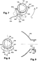
- connection support 500 has a hole 506 formed at one of its ends. It also comprises a locking tab 507, disposed at its other end, said free end, two leaf spring 508 and a locking tab 509 whose functions are now described with reference to the figure 6 .
- the reflector 100 comprises, close to the flange 104, a rotational pivot 600, terminated by a thinner end 601 intended to be housed in the hole 506 of the connection support 500.
- the connection support 500 can thus be be placed by translational movement on the reflector 100 in an unlocked position, shown in phantom at the figure 7 .
- the connection support 500 can then be brought into the locked position, shown in solid lines, by a rotational movement DD 'about the pivot 600.
- the latter is designed so that it deforms slightly to crossing the retaining lug 602 during the locking movement, to resume its initial position once the retaining lug 602 passed.
- the locking tab 509 is introduced into a cavity 603 formed in the flange 104.
- the locking tab 509 extends horizontally in the plane of rotation. Once introduced into the cavity 603, it therefore prevents the connection support 500 from moving in translation along the optical axis; any rotational movement being made impossible by the retaining lug 602, the connection support 500 is, in its locked position, perfectly locked.
- the spring blades 508 are arranged such that they press, deforming, on the flange 104 at the end of the locking movement. If the locking is not correctly performed, that is to say if the locking tab 507 has not completely exceeded the retention lug 602, the leaf spring 508, by the pressure they exert on the collar 104 , push back the connection support 500 in a direction opposite to the locking direction, thus clearly showing that the locking has not been performed correctly.
- the locking tab 509 is disposed between the leaf spring 508 as an example embodiment.
- FIGS. 8 and 9 show a second embodiment of the projector device according to the invention.
- the rotation pivot 600 of the first example is replaced by holding elements 800 disposed on the reflector 100, close to the flange 104.
- the holding elements are guide rails which extend parallel to the optical axis. These guide rails cooperate with complementary slides 801 disposed on the connection support 500 to bring the connection support into its locked position only by a translation movement parallel to the optical axis.
- the connection support no longer has a hole 506, spring blades 508, or locking tab 507. The locking tab 509 is still present.
- the locking tab consists of a first thin portion 900 extending along the flange 104, outside the latter, and a second portion 901, constituted by a lug, a hook, s' extending perpendicular to the first part.
- the locking tab 509 is slightly deformed to slide on the outer face of the flange 104 until the lug 901 arrives in a cavity 902 in which it is introduced by elasticity of the locking tab 509. The connection support is thus locked in its locked position.
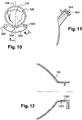
- the Figures 10, 11 and 12 show a third embodiment of the projector device according to the invention.
- the holding elements 800 disposed on the reflector 100, close to the flange 104 are fixing studs which extend parallel to the optical axis.
- These fixing studs cooperate with the hole 506, already present in the first example described, and with a second hole 1000 disposed on the opposite end of the connection support 500 to that comprising the first hole 506, as seen in FIG. figure 11 ; this figure is a sectional view of the projection along the direction referenced B on the figure 10 locked position.
- the two holes 506 and 1000 replace the complementary slides 801 of the second example described.
- the connection support 500 can be brought into its locked position only by a translation movement parallel to the optical axis.
- the locking tab 509 is still present. As we see in figure 12 , which is a sectional view of the projection in the direction referenced A on the figure 10 it always consists of a first thin part 1200 extending along the flange 104, but inside the latter, and a second part 1201, constituted by a lug, a hook, extending perpendicular to the first part. During the locking movement by translation, the locking tab 509 is thus slightly deformed to slide on the inner face of the flange 104 until the lug 1201 arrives in a cavity 1202 into which it is introduced by elasticity. the locking tab 509. The connection support is thus locked in its locked position.
- the locking tabs 509 may be interchanged: that used in the second embodiment may be used in the third embodiment, and that used in the third embodiment may be used in the second embodiment.
- the locking lug 509 is introduced through the inside of the collar 104, it is possible to use as cavity 1202 one of the recesses 108 completing the opening 103 which is provided with the flange 104 of the reflector 100. The clearance 108 is then substantially extended so as to simultaneously pass a locking tab 207 and the locking tab 509.
- the various elements added for the purpose of the invention to the reflector 100 namely the pivot in rotation 600, the retention pin 602, or the various examples of holding elements 800 extend. parallel to the optical axis, without cavity formed in their body; they do not require the addition of drawers in the mold used to make the reflector.
- connection support 500 completely surrounds the collar 104.
- the connection support 500 is then an approximately circular piece, which is arranged in translation on the reflector 100. It can in particular be maintained by means of two legs of blocking, of the type of those appearing in the previously described examples; in a particular example, the two locking tabs are diametrically opposed.
Landscapes
- Engineering & Computer Science (AREA)
- General Engineering & Computer Science (AREA)
- Non-Portable Lighting Devices Or Systems Thereof (AREA)
Claims (11)
- Scheinwerfervorrichtung, insbesondere mit:- einer Lichtquelle (200) mit einer Lampe (201), einem Lampenhalter (202), einer Reihe von Anschlusszungen (206) und wenigstens einem Verriegelungsfuss (207);- einem eine Innenseite (102) und eine Außenseite (101) aufweisenden Reflektor (100), wobei der Reflektor (100) einen Kragen (104) aufweist, der mit einer durch eine Reihe von Ausnehmungen (108) ergänzten kreisförmigen Öffnung (103) versehen ist, in deren Nähe die Lichtquelle (200) den Reflektor (100) zwischen den Verriegelungsarmen (207), in Kontakt mit der Innenseite (102), und einem der Außenseite (101) des Reflektors (100) gegenüberliegenden Abschnitt (208) des Halters (202) einklemmt,wobei die Scheinwerfervorrichtung einen Verbindungsträger (500) umfasst, der dazu bestimmt ist, an der Außenseite (101) des Reflektors (100) befestigt zu sein, wobei der Verbindungsträger (500) eine Reihe von Gegenstücken (505) elektrischer Verbindungsmittel umfasst, um in einer verriegelten Stellung nach einer erfolgten Verriegelung der Lichtquelle (200) am Reflektor (100) eine elektrische Verbindung mit den Anschlusszungen (206) zu gewährleisten, wobei die Außenseite (101) des Reflektors (100) wenigstens ein Halteelement (800) umfasst, um den Verbindungsträger (500) durch eine Translationsbewegung in die verriegelte Stellung zu bringen,
dadurch gekennzeichnet, dass der Verbindungsträger (500) abnehmbar ist. - Scheinwerfervorrichtung nach dem vorhergehenden Anspruch,
dadurch gekennzeichnet, dass der Verbindungsträger (500) eine Anzahl von Gegenstücken (505) elektrischer Verbindungsmittel aufweist, die wenigstens der Anzahl der an der Lichtquelle (200) vorhandenen Anschlusszungen (206) entspricht. - Scheinwerfervorrichtung nach wenigstens einem der vorhergehenden Ansprüche,
dadurch gekennzeichnet, dass jedes Gegenstück (505) elektrischer Verbindungsmittel an einem geschlossenen Ende einer in der Dicke des Verbindungsträgers (500) ausgebildeten Höhlung (501) angeordnet ist, wobei jede Anschlusszunge (206) während des Verriegelungsvorgangs durch eine Drehbewegung der Lichtquelle (200) bezüglich des Reflektors (100) in eines der Gegenstücke (505) elektrischer Verbindungsmittel gebracht wird, wobei der Verriegelungsvorgang auf eine translatorische Bewegung der Lichtquelle (200) durch die Öffnung (103) des Reflektors (100) hindurch folgt, in deren Verlauf jede Anschlusszunge (206) in eine der Höhlungen (501) des Verbindungsträgers durch ein offenes Ende (510) der betreffenden Höhlung (505) eingeführt wird. - Scheinwerfervorrichtung nach wenigstens einem der vorhergehenden Ansprüche,
dadurch gekennzeichnet, dass die Halteelemente (800) zwei Befestigungsstifte sind, wobei jeder Befestigungsstift in eine passende Höhlung (506; 1000) des Verbindungsträgers (500) eingreift, um den Verbindungsträger (500) in seiner verriegelten Stellung zu halten. - Scheinwerfervorrichtung nach wenigstens einem der Ansprüche 1 bis 3, dadurch gekennzeichnet, dass die Halteelemente (800) zwei Führungsschienen sind, gegen die sich der Verbindungsträger (500) translatorisch bewegt, um in der verriegelten Stellung positioniert zu werden.
- Scheinwerfervorrichtung nach einem der vorhergehenden Ansprüche, dadurch gekennzeichnet, dass der Verbindungsträger (500) den Kragen (104) teilweise oder vollständig umgibt.
- Scheinwerfervorrichtung nach wenigstens einem der vorhergehenden Ansprüche,
dadurch gekennzeichnet, dass der Verbindungsträger (500) wenigstens einen Arretierarm (509) aufweist, um den Verbindungsträger (500) daran zu hindern, sich translatorisch zu bewegen, nachdem er sich in der verriegelten Stellung befindet. - Scheinwerfervorrichtung nach dem vorhergehenden Anspruch,
dadurch gekennzeichnet, dass der Arretierarm (509) einen Nocken (901; 1201) aufweist, der, wenn sich der Verbindungsträger (500) in der verriegelten Stellung befindet, in einer im Kragen (104) des Reflektors (100) ausgebildeten speziellen Höhlung (902) platziert ist. - Scheinwerfervorrichtung nach Anspruch 8,
dadurch gekennzeichnet, dass der Arretierarm (509) einen Nocken (901; 1201) aufweist, der, wenn sich der Verbindungsträger (500) in der verriegelten Stellung befindet, in einer der Ausnehmungen (108) platziert ist, welche die Öffnung (103) ergänzen, mit der der Kragen (104) des Reflektors (100) versehen ist. - Scheinwerfervorrichtung nach wenigstens einem der vorhergehenden Ansprüche,
dadurch gekennzeichnet, dass wenigstens eine Verriegelungszunge (207) nach der erfolgten Verriegelung in Anlage gegen einen Anschlag (304) gebracht ist. - Kraftfahrzeug, ausgestattet mit einer Scheinwerfervorrichtung nach wenigstens einem der Ansprüche 1 bis 10.
Applications Claiming Priority (2)
| Application Number | Priority Date | Filing Date | Title |
|---|---|---|---|
| FR0312832 | 2003-10-31 | ||
| FR0312832A FR2861835B1 (fr) | 2003-10-31 | 2003-10-31 | Dispositif projecteur avec support de connexion pour lampe a verrouillage |
Publications (3)
| Publication Number | Publication Date |
|---|---|
| EP1528314A2 EP1528314A2 (de) | 2005-05-04 |
| EP1528314A3 EP1528314A3 (de) | 2013-04-03 |
| EP1528314B1 true EP1528314B1 (de) | 2017-04-19 |
Family
ID=34400898
Family Applications (1)
| Application Number | Title | Priority Date | Filing Date |
|---|---|---|---|
| EP04292524.8A Expired - Lifetime EP1528314B1 (de) | 2003-10-31 | 2004-10-25 | Kfz-Scheinwerfer mit einem Verbindungsträger für eine verriegelbare Lampe |
Country Status (2)
| Country | Link |
|---|---|
| EP (1) | EP1528314B1 (de) |
| FR (1) | FR2861835B1 (de) |
Families Citing this family (2)
| Publication number | Priority date | Publication date | Assignee | Title |
|---|---|---|---|---|
| DE102005033882B4 (de) * | 2005-07-20 | 2015-04-09 | Automotive Lighting Reutlingen Gmbh | Beleuchtungseinrichtung für Kraftfahrzeuge, Baugruppe für eine solche Beleuchtungseinrichtung und Verfahren zur Montage einer solchen Beleuchtungseinrichtung |
| CN107166190B (zh) * | 2017-06-09 | 2021-02-02 | 漳州立达信光电子科技有限公司 | 一种led灯丝灯 |
Family Cites Families (6)
| Publication number | Priority date | Publication date | Assignee | Title |
|---|---|---|---|---|
| US4500946A (en) * | 1982-01-13 | 1985-02-19 | Ford Motor Company | Replaceable lamp assembly for a sealable reflector housing |
| US4573754A (en) * | 1984-03-14 | 1986-03-04 | U.S. Plastics Corp. | Lamp assembly |
| DE8815069U1 (de) * | 1988-12-03 | 1990-04-26 | Robert Bosch Gmbh, 7000 Stuttgart | Scheinwerfer für Fahrzeuge, insbesondere für Kraftfahrzeuge |
| JP3992735B2 (ja) * | 1995-09-25 | 2007-10-17 | コーニンクレッカ フィリップス エレクトロニクス エヌ ヴイ | キャップ付き電球、及び反射器と該反射器に組み合わされるキャップ付き電球とを有する照明システム |
| JP3280284B2 (ja) * | 1997-07-25 | 2002-04-30 | スタンレー電気株式会社 | 前照灯灯具 |
| FR2829304B1 (fr) * | 2001-08-31 | 2004-09-17 | Valeo Vision | Agencement pour la connexion electrique d'une lampe |
-
2003
- 2003-10-31 FR FR0312832A patent/FR2861835B1/fr not_active Expired - Fee Related
-
2004
- 2004-10-25 EP EP04292524.8A patent/EP1528314B1/de not_active Expired - Lifetime
Non-Patent Citations (1)
| Title |
|---|
| None * |
Also Published As
| Publication number | Publication date |
|---|---|
| FR2861835A1 (fr) | 2005-05-06 |
| EP1528314A2 (de) | 2005-05-04 |
| EP1528314A3 (de) | 2013-04-03 |
| FR2861835B1 (fr) | 2006-08-11 |
Similar Documents
| Publication | Publication Date | Title |
|---|---|---|
| EP1801494B1 (de) | Lampenträger für Scheinwerfer mit bezüglich der Lampenträger Wand tangentialen Kontaktkrallen | |
| EP3299710B1 (de) | Leuchtmodul und leuchtvorrichtung für kraftfahrzeug, das ein solches leuchtmodul umfasst | |
| EP3292021A1 (de) | Fahrzeug mit an einem scheinwerfer angebrachtem steinschild | |
| EP0145556A1 (de) | Einrichtung zum Montieren und Befestigen einer Lampe, insbesondere für Kraftfahrzeugscheinwerfer | |
| EP3489576A1 (de) | Leuchtmodul zur beleuchtung und/oder signalisierung eines kraftfahrzeugs | |
| EP1528314B1 (de) | Kfz-Scheinwerfer mit einem Verbindungsträger für eine verriegelbare Lampe | |
| EP1455134B1 (de) | Befestigungsvorrichtung für eine Lampe | |
| EP1679472B1 (de) | Vorrichtung zur Befestigung einer Lampe auf einer Lampenfassung für Kfz-Scheinwerfer | |
| FR2630193A1 (fr) | Systeme de montage de lampes de differents types sur le reflecteur d'un projecteur | |
| EP1288566A2 (de) | Elektrische Verbindungsanordnung für Lampe | |
| FR2835595A1 (fr) | Douille de lampe pour projecteur de vehicule automobile, et reflecteur de projecteur destine a recevoir une telle douille de lampe. | |
| EP1533563A1 (de) | Vorrichtung und Verfahren zur Befestigung einer Lichtquelle an einem Teil eines Kfz-Scheinwerfers | |
| EP1633024A1 (de) | Steckfassung für eine Keilbasislampe mit Zentrierring | |
| EP1867918B1 (de) | Scheinwerfer, der ein feststehendes, aufgesetztes Halterungselement umfasst, auf dem ein Scheinwerfer schwenkbar montiert ist | |
| FR2805599A1 (fr) | Systeme de fixation d'une source lumineuse dans le reflecteur d'un projecteur | |
| EP1544538B1 (de) | Kfz-Scheinwerfer mit einem Lampenträger | |
| FR2860858A1 (fr) | Reflecteur et douille de lampe de projecteur de vehicule automobile. | |
| FR2835594A1 (fr) | Douille de lampe pour projecteur de vehicule automobile, et reflecteur de projecteur destine a recevoir une telle douille de lampe | |
| WO2011131894A1 (fr) | Douille a double verrouillage pour ampoule electrique | |
| FR2646567A1 (fr) | Ensemble de connecteur et de lampe a haute tension a haute securite, notamment pour eclairage automobile | |
| EP2952804A1 (de) | Leuchtmodul für fahrzeug und befestigungsverfahren | |
| FR2835593A1 (fr) | Douille de lampe pour projecteur de vehicule automobile, et reflecteur de projecteur destine a recevoir une telle douille de lampe | |
| EP1878967B1 (de) | Invertierte, abgeschnittene Halterung, die zur Aufnahme einer Buchse einer Lichtquelle einer Projektionsvorrichtung dient | |
| FR2973478A1 (fr) | Dispositif de centrage d'une lentille pour dispositif d'eclairage et / ou de signalisation d'un vehicule | |
| EP4605684A1 (de) | Optische einheit für ein fahrzeug mit einem kühlkörper |
Legal Events
| Date | Code | Title | Description |
|---|---|---|---|
| PUAI | Public reference made under article 153(3) epc to a published international application that has entered the european phase |
Free format text: ORIGINAL CODE: 0009012 |
|
| AK | Designated contracting states |
Kind code of ref document: A2 Designated state(s): AT BE BG CH CY CZ DE DK EE ES FI FR GB GR HU IE IT LI LU MC NL PL PT RO SE SI SK TR |
|
| AX | Request for extension of the european patent |
Extension state: AL HR LT LV MK |
|
| PUAL | Search report despatched |
Free format text: ORIGINAL CODE: 0009013 |
|
| AK | Designated contracting states |
Kind code of ref document: A3 Designated state(s): AT BE BG CH CY CZ DE DK EE ES FI FR GB GR HU IE IT LI LU MC NL PL PT RO SE SI SK TR |
|
| AX | Request for extension of the european patent |
Extension state: AL HR LT LV MK |
|
| RIC1 | Information provided on ipc code assigned before grant |
Ipc: F21V 19/00 20060101AFI20130225BHEP Ipc: F21S 8/12 20060101ALI20130225BHEP |
|
| RBV | Designated contracting states (corrected) |
Designated state(s): AT BE BG CH CY CZ DE DK EE ES FI FR GB GR HU IE IT LI LU MC NL PL PT RO SE SI SK TR |
|
| RBV | Designated contracting states (corrected) |
Designated state(s): AT BE BG CH CY CZ DE DK EE ES FI FR GB GR HU IE IT LI LU MC NL PL PT RO SE SI SK TR |
|
| 17P | Request for examination filed |
Effective date: 20130927 |
|
| RBV | Designated contracting states (corrected) |
Designated state(s): AT BE BG CH CY CZ DE DK EE ES FI FR GB GR HU IE IT LI LU MC NL PL PT RO SE SI SK TR |
|
| 17Q | First examination report despatched |
Effective date: 20131104 |
|
| AKX | Designation fees paid |
Designated state(s): AT BE BG CH CY CZ DE DK EE ES FI FR GB GR HU IE IT LI LU MC NL PL PT RO SE SI SK TR |
|
| GRAP | Despatch of communication of intention to grant a patent |
Free format text: ORIGINAL CODE: EPIDOSNIGR1 |
|
| RIC1 | Information provided on ipc code assigned before grant |
Ipc: F21S 8/10 20060101ALI20161021BHEP Ipc: F21V 19/00 20060101AFI20161021BHEP Ipc: F21S 8/12 20060101ALI20161021BHEP |
|
| INTG | Intention to grant announced |
Effective date: 20161110 |
|
| GRAS | Grant fee paid |
Free format text: ORIGINAL CODE: EPIDOSNIGR3 |
|
| GRAA | (expected) grant |
Free format text: ORIGINAL CODE: 0009210 |
|
| AK | Designated contracting states |
Kind code of ref document: B1 Designated state(s): AT BE BG CH CY CZ DE DK EE ES FI FR GB GR HU IE IT LI LU MC NL PL PT RO SE SI SK TR |
|
| REG | Reference to a national code |
Ref country code: GB Ref legal event code: FG4D Free format text: NOT ENGLISH |
|
| REG | Reference to a national code |
Ref country code: CH Ref legal event code: EP |
|
| REG | Reference to a national code |
Ref country code: AT Ref legal event code: REF Ref document number: 886340 Country of ref document: AT Kind code of ref document: T Effective date: 20170515 |
|
| REG | Reference to a national code |
Ref country code: IE Ref legal event code: FG4D Free format text: LANGUAGE OF EP DOCUMENT: FRENCH |
|
| REG | Reference to a national code |
Ref country code: DE Ref legal event code: R096 Ref document number: 602004051107 Country of ref document: DE |
|
| REG | Reference to a national code |
Ref country code: NL Ref legal event code: MP Effective date: 20170419 |
|
| REG | Reference to a national code |
Ref country code: AT Ref legal event code: MK05 Ref document number: 886340 Country of ref document: AT Kind code of ref document: T Effective date: 20170419 |
|
| PG25 | Lapsed in a contracting state [announced via postgrant information from national office to epo] |
Ref country code: NL Free format text: LAPSE BECAUSE OF FAILURE TO SUBMIT A TRANSLATION OF THE DESCRIPTION OR TO PAY THE FEE WITHIN THE PRESCRIBED TIME-LIMIT Effective date: 20170419 |
|
| PG25 | Lapsed in a contracting state [announced via postgrant information from national office to epo] |
Ref country code: FI Free format text: LAPSE BECAUSE OF FAILURE TO SUBMIT A TRANSLATION OF THE DESCRIPTION OR TO PAY THE FEE WITHIN THE PRESCRIBED TIME-LIMIT Effective date: 20170419 Ref country code: ES Free format text: LAPSE BECAUSE OF FAILURE TO SUBMIT A TRANSLATION OF THE DESCRIPTION OR TO PAY THE FEE WITHIN THE PRESCRIBED TIME-LIMIT Effective date: 20170419 Ref country code: GR Free format text: LAPSE BECAUSE OF FAILURE TO SUBMIT A TRANSLATION OF THE DESCRIPTION OR TO PAY THE FEE WITHIN THE PRESCRIBED TIME-LIMIT Effective date: 20170720 Ref country code: AT Free format text: LAPSE BECAUSE OF FAILURE TO SUBMIT A TRANSLATION OF THE DESCRIPTION OR TO PAY THE FEE WITHIN THE PRESCRIBED TIME-LIMIT Effective date: 20170419 |
|
| PG25 | Lapsed in a contracting state [announced via postgrant information from national office to epo] |
Ref country code: BG Free format text: LAPSE BECAUSE OF FAILURE TO SUBMIT A TRANSLATION OF THE DESCRIPTION OR TO PAY THE FEE WITHIN THE PRESCRIBED TIME-LIMIT Effective date: 20170719 Ref country code: PL Free format text: LAPSE BECAUSE OF FAILURE TO SUBMIT A TRANSLATION OF THE DESCRIPTION OR TO PAY THE FEE WITHIN THE PRESCRIBED TIME-LIMIT Effective date: 20170419 Ref country code: SE Free format text: LAPSE BECAUSE OF FAILURE TO SUBMIT A TRANSLATION OF THE DESCRIPTION OR TO PAY THE FEE WITHIN THE PRESCRIBED TIME-LIMIT Effective date: 20170419 |
|
| REG | Reference to a national code |
Ref country code: DE Ref legal event code: R097 Ref document number: 602004051107 Country of ref document: DE |
|
| PG25 | Lapsed in a contracting state [announced via postgrant information from national office to epo] |
Ref country code: SK Free format text: LAPSE BECAUSE OF FAILURE TO SUBMIT A TRANSLATION OF THE DESCRIPTION OR TO PAY THE FEE WITHIN THE PRESCRIBED TIME-LIMIT Effective date: 20170419 Ref country code: EE Free format text: LAPSE BECAUSE OF FAILURE TO SUBMIT A TRANSLATION OF THE DESCRIPTION OR TO PAY THE FEE WITHIN THE PRESCRIBED TIME-LIMIT Effective date: 20170419 Ref country code: CZ Free format text: LAPSE BECAUSE OF FAILURE TO SUBMIT A TRANSLATION OF THE DESCRIPTION OR TO PAY THE FEE WITHIN THE PRESCRIBED TIME-LIMIT Effective date: 20170419 Ref country code: RO Free format text: LAPSE BECAUSE OF FAILURE TO SUBMIT A TRANSLATION OF THE DESCRIPTION OR TO PAY THE FEE WITHIN THE PRESCRIBED TIME-LIMIT Effective date: 20170419 Ref country code: DK Free format text: LAPSE BECAUSE OF FAILURE TO SUBMIT A TRANSLATION OF THE DESCRIPTION OR TO PAY THE FEE WITHIN THE PRESCRIBED TIME-LIMIT Effective date: 20170419 |
|
| PLBE | No opposition filed within time limit |
Free format text: ORIGINAL CODE: 0009261 |
|
| STAA | Information on the status of an ep patent application or granted ep patent |
Free format text: STATUS: NO OPPOSITION FILED WITHIN TIME LIMIT |
|
| PG25 | Lapsed in a contracting state [announced via postgrant information from national office to epo] |
Ref country code: IT Free format text: LAPSE BECAUSE OF FAILURE TO SUBMIT A TRANSLATION OF THE DESCRIPTION OR TO PAY THE FEE WITHIN THE PRESCRIBED TIME-LIMIT Effective date: 20170419 |
|
| 26N | No opposition filed |
Effective date: 20180122 |
|
| REG | Reference to a national code |
Ref country code: DE Ref legal event code: R119 Ref document number: 602004051107 Country of ref document: DE |
|
| PG25 | Lapsed in a contracting state [announced via postgrant information from national office to epo] |
Ref country code: MC Free format text: LAPSE BECAUSE OF FAILURE TO SUBMIT A TRANSLATION OF THE DESCRIPTION OR TO PAY THE FEE WITHIN THE PRESCRIBED TIME-LIMIT Effective date: 20170419 Ref country code: SI Free format text: LAPSE BECAUSE OF FAILURE TO SUBMIT A TRANSLATION OF THE DESCRIPTION OR TO PAY THE FEE WITHIN THE PRESCRIBED TIME-LIMIT Effective date: 20170419 |
|
| REG | Reference to a national code |
Ref country code: CH Ref legal event code: PL |
|
| GBPC | Gb: european patent ceased through non-payment of renewal fee |
Effective date: 20171025 |
|
| REG | Reference to a national code |
Ref country code: IE Ref legal event code: MM4A |
|
| REG | Reference to a national code |
Ref country code: FR Ref legal event code: ST Effective date: 20180629 |
|
| PG25 | Lapsed in a contracting state [announced via postgrant information from national office to epo] |
Ref country code: DE Free format text: LAPSE BECAUSE OF NON-PAYMENT OF DUE FEES Effective date: 20180501 Ref country code: LU Free format text: LAPSE BECAUSE OF NON-PAYMENT OF DUE FEES Effective date: 20171025 Ref country code: LI Free format text: LAPSE BECAUSE OF NON-PAYMENT OF DUE FEES Effective date: 20171031 Ref country code: GB Free format text: LAPSE BECAUSE OF NON-PAYMENT OF DUE FEES Effective date: 20171025 Ref country code: CH Free format text: LAPSE BECAUSE OF NON-PAYMENT OF DUE FEES Effective date: 20171031 |
|
| REG | Reference to a national code |
Ref country code: BE Ref legal event code: MM Effective date: 20171031 |
|
| PG25 | Lapsed in a contracting state [announced via postgrant information from national office to epo] |
Ref country code: FR Free format text: LAPSE BECAUSE OF NON-PAYMENT OF DUE FEES Effective date: 20171031 Ref country code: BE Free format text: LAPSE BECAUSE OF NON-PAYMENT OF DUE FEES Effective date: 20171031 |
|
| PG25 | Lapsed in a contracting state [announced via postgrant information from national office to epo] |
Ref country code: IE Free format text: LAPSE BECAUSE OF NON-PAYMENT OF DUE FEES Effective date: 20171025 |
|
| PG25 | Lapsed in a contracting state [announced via postgrant information from national office to epo] |
Ref country code: HU Free format text: LAPSE BECAUSE OF FAILURE TO SUBMIT A TRANSLATION OF THE DESCRIPTION OR TO PAY THE FEE WITHIN THE PRESCRIBED TIME-LIMIT; INVALID AB INITIO Effective date: 20041025 |
|
| PG25 | Lapsed in a contracting state [announced via postgrant information from national office to epo] |
Ref country code: CY Free format text: LAPSE BECAUSE OF NON-PAYMENT OF DUE FEES Effective date: 20170419 |
|
| PG25 | Lapsed in a contracting state [announced via postgrant information from national office to epo] |
Ref country code: TR Free format text: LAPSE BECAUSE OF FAILURE TO SUBMIT A TRANSLATION OF THE DESCRIPTION OR TO PAY THE FEE WITHIN THE PRESCRIBED TIME-LIMIT Effective date: 20170419 |
|
| PG25 | Lapsed in a contracting state [announced via postgrant information from national office to epo] |
Ref country code: PT Free format text: LAPSE BECAUSE OF FAILURE TO SUBMIT A TRANSLATION OF THE DESCRIPTION OR TO PAY THE FEE WITHIN THE PRESCRIBED TIME-LIMIT Effective date: 20170419 |